EP3210912B1 - Dispositif d'évacuation - Google Patents
Dispositif d'évacuation Download PDFInfo
- Publication number
- EP3210912B1 EP3210912B1 EP17157336.3A EP17157336A EP3210912B1 EP 3210912 B1 EP3210912 B1 EP 3210912B1 EP 17157336 A EP17157336 A EP 17157336A EP 3210912 B1 EP3210912 B1 EP 3210912B1
- Authority
- EP
- European Patent Office
- Prior art keywords
- storage tank
- wall
- filling
- opening
- disposal device
- Prior art date
- Legal status (The legal status is an assumption and is not a legal conclusion. Google has not performed a legal analysis and makes no representation as to the accuracy of the status listed.)
- Active
Links
Images


Classifications
-
- B—PERFORMING OPERATIONS; TRANSPORTING
- B65—CONVEYING; PACKING; STORING; HANDLING THIN OR FILAMENTARY MATERIAL
- B65F—GATHERING OR REMOVAL OF DOMESTIC OR LIKE REFUSE
- B65F1/00—Refuse receptacles; Accessories therefor
- B65F1/10—Refuse receptacles; Accessories therefor with refuse filling means, e.g. air-locks
-
- B—PERFORMING OPERATIONS; TRANSPORTING
- B65—CONVEYING; PACKING; STORING; HANDLING THIN OR FILAMENTARY MATERIAL
- B65F—GATHERING OR REMOVAL OF DOMESTIC OR LIKE REFUSE
- B65F1/00—Refuse receptacles; Accessories therefor
- B65F1/12—Refuse receptacles; Accessories therefor with devices facilitating emptying
- B65F1/127—Refuse receptacles; Accessories therefor with devices facilitating emptying by suction
-
- B—PERFORMING OPERATIONS; TRANSPORTING
- B65—CONVEYING; PACKING; STORING; HANDLING THIN OR FILAMENTARY MATERIAL
- B65F—GATHERING OR REMOVAL OF DOMESTIC OR LIKE REFUSE
- B65F1/00—Refuse receptacles; Accessories therefor
- B65F1/14—Other constructional features; Accessories
- B65F1/1426—Housings, cabinets or enclosures for refuse receptacles
- B65F1/1447—Housings, cabinets or enclosures for refuse receptacles located underground
-
- B—PERFORMING OPERATIONS; TRANSPORTING
- B65—CONVEYING; PACKING; STORING; HANDLING THIN OR FILAMENTARY MATERIAL
- B65F—GATHERING OR REMOVAL OF DOMESTIC OR LIKE REFUSE
- B65F7/00—Cleaning or disinfecting devices combined with refuse receptacles or refuse vehicles
-
- C—CHEMISTRY; METALLURGY
- C05—FERTILISERS; MANUFACTURE THEREOF
- C05F—ORGANIC FERTILISERS NOT COVERED BY SUBCLASSES C05B, C05C, e.g. FERTILISERS FROM WASTE OR REFUSE
- C05F17/00—Preparation of fertilisers characterised by biological or biochemical treatment steps, e.g. composting or fermentation
- C05F17/90—Apparatus therefor
- C05F17/907—Small-scale devices without mechanical means for feeding or discharging material, e.g. garden compost bins
-
- B—PERFORMING OPERATIONS; TRANSPORTING
- B65—CONVEYING; PACKING; STORING; HANDLING THIN OR FILAMENTARY MATERIAL
- B65F—GATHERING OR REMOVAL OF DOMESTIC OR LIKE REFUSE
- B65F1/00—Refuse receptacles; Accessories therefor
- B65F1/14—Other constructional features; Accessories
- B65F2001/1489—Refuse receptacles adapted or modified for gathering compostable domestic refuse
-
- Y—GENERAL TAGGING OF NEW TECHNOLOGICAL DEVELOPMENTS; GENERAL TAGGING OF CROSS-SECTIONAL TECHNOLOGIES SPANNING OVER SEVERAL SECTIONS OF THE IPC; TECHNICAL SUBJECTS COVERED BY FORMER USPC CROSS-REFERENCE ART COLLECTIONS [XRACs] AND DIGESTS
- Y02—TECHNOLOGIES OR APPLICATIONS FOR MITIGATION OR ADAPTATION AGAINST CLIMATE CHANGE
- Y02P—CLIMATE CHANGE MITIGATION TECHNOLOGIES IN THE PRODUCTION OR PROCESSING OF GOODS
- Y02P20/00—Technologies relating to chemical industry
- Y02P20/141—Feedstock
- Y02P20/145—Feedstock the feedstock being materials of biological origin
-
- Y—GENERAL TAGGING OF NEW TECHNOLOGICAL DEVELOPMENTS; GENERAL TAGGING OF CROSS-SECTIONAL TECHNOLOGIES SPANNING OVER SEVERAL SECTIONS OF THE IPC; TECHNICAL SUBJECTS COVERED BY FORMER USPC CROSS-REFERENCE ART COLLECTIONS [XRACs] AND DIGESTS
- Y02—TECHNOLOGIES OR APPLICATIONS FOR MITIGATION OR ADAPTATION AGAINST CLIMATE CHANGE
- Y02W—CLIMATE CHANGE MITIGATION TECHNOLOGIES RELATED TO WASTEWATER TREATMENT OR WASTE MANAGEMENT
- Y02W30/00—Technologies for solid waste management
- Y02W30/40—Bio-organic fraction processing; Production of fertilisers from the organic fraction of waste or refuse
Definitions
- the invention relates to a disposal device according to the preamble of claim 1.
- organic waste is found in food preparation, spoilage, overproduction of meals, and in the form of leftovers on individual plates already delivered to consumers.
- organic waste is usually collected in the kitchen in various containers.
- garbage cans generates high noise and emission nuisances due to truck pick-up trips.
- the cleaning and disinfection of garbage cans not only requires a high manpower, resulting in high costs, but also chemicals that are costly and pollute the environment.
- garbage cans For example, special inserts, as in DE 102 02 181 A1 described, are used. Nevertheless, the components of this garbage can need to be cleaned and disinfected consuming, which further increases the labor and logistics costs. In addition, cooling must be provided in particular at high temperatures, so that odor pollution and nucleation are inhibited.
- DE 699 25 432 T2 describes an alternative food waste disposal system wherein the input food residues are first crushed to be dewatered and compacted. Although this requires less space for a collection container, the space required for the arrangement is also very high. In addition, such a system is not only expensive to purchase but also leads to high energy and maintenance costs.
- US 5 568 996 B discloses a system for processing and storing organic waste, wherein a storage tank is provided with an opening in the confining wall of the storage tank, which is connected to a filling unit having a filling opening.
- the arrangement also includes a rolling mill for shredding the waste and reducing the waste volume.
- a publication in the database WPI, Week 201641, Thomson Scientific, London, GB and CN 105 154 475 A describe a process for recycling kitchen waste that is stored in a fermentation arrangement for the production of biogas.
- the storage tank is limited by a wall heated with hot water.
- a filling unit with a filling opening is connected to the storage tank.
- US 2011/101137 A shows a waste packaging system with a shredder and a packaging device.
- the waste passes from a filling opening via a filling unit into a storage container which is sealable and replaceable.
- a water adding device is arranged, which mixes water to the waste to allow easy crushing and homogenization of the waste.
- WO 96/05154 A1 discloses a method of handling organic waste and associated equipment. This comprises a storage tank, which is arranged underground and can be filled via a funnel-shaped filling unit with a filling opening with organic waste.
- a disposal system for biowaste is known, with a storage tank and a sluice gate with a movable chute and a cleaning system for the chute. Its opening is closed with a flap or a sliding lid. Controls for locking the disposal device and starting the disposal procedure are located next to the flap.
- EP 2 284 105 A1 discloses a waste container with a storage tank embedded in the ground.
- the walls of the storage tank have no limitation upwards, so that the storage tank is open at the top.
- another, replaceable waste container is provided in the storage tank.
- the object of the invention is therefore to overcome the existing disadvantages of the prior art and to provide a disposal device for organic waste, which is space-saving, cost-effective and environmentally friendly and can be flexibly adapted to potential volume fluctuations of the resulting organic waste.
- the odor nuisance and nucleation should be kept as low as possible, without the use of chemicals or electrical cooling is necessary.
- an organic waste disposal apparatus having a storage tank having a wall, and at least one opening, the wall defining the storage tank to the outside, the at least one opening being disposed in the wall, and a filling unit, the filling unit having a Has filling opening and is connected to the opening in the wall of the storage tank, and wherein the wall of the storage tank is at least partially embedded in a thermal mass, characterized in that the filling unit, which the filling opening with the opening in the wall of the Storage tank connects, at least partially funnel-shaped and formed in the disposal direction tapered and having a lid which closes the filling opening to the outside, the lid having an overlapping edge and / or a seal, wherein the filling unit is provided with a water purification device, which at a lower End of the funnel is arranged and has a nozzle for dispensing and distribution of water, wherein the nozzle opens within the filling unit and wherein the water purification device has a triggering device which is arranged as a contact plate on the outside of the filling unit at
- the structure of the invention allows the filling of organic waste into the through the filling opening in the filling unit, from which the waste via the opening directly into the storage tank. There occurs a fermentation of organic waste by bacteria, which can lead to a high odor burden.
- the inventive contact of the walls of the storage tank with a thermal mass heat generated during the fermentation, as well as heat is derived by input organic waste. This causes a cooling of the storage tank contents without additional electrical cooling is necessary.
- a natural cooling effect causes the organic waste to be fermented exclusively to carbon dioxide, which as a protective bell covers the organic residues. As a result, both an odor nuisance by rising, odor-intensive gases, as well as the proliferation of germs is avoided.
- the disposal device is inexpensive both in the purchase, as well as in operation, since, for example, no additional cooling device is needed. Furthermore, the storage tank can be flexibly designed for volume fluctuations in organic waste.
- the shape of the funnel tapering in the direction of disposal prevents large objects, such as a trash can, from falling into the storage tank, on the other hand it can be ensured that as little carbon dioxide as possible, the protective layer in the storage tank, is swirled up.
- the funnel can have, for example, a square, quadrangular, octagonal or round cross-section.
- the lid closes the disposal device temporarily and can be opened as needed.
- the lid can be opened and closed automatically, for example manually and / or with the aid of a sensor.
- the lid closes the disposal device against external environmental influences, for example heavy rain or storm, intrusion of larger alien objects, such as branches or raccoons, and thus protects the carbon dioxide protective layer against turbulence and the storage tank from contamination. In addition, potential odor nuisances due to escaping odor-intensive gases are further reduced.
- the seal can be provided, for example in the form of a sealing ring which seals the filling unit and the lid to each other.
- the water purification device allows the cleaning of a transport container or trash can, which is used for introducing the organic waste. This gets it clean again in the kitchen.
- the organic waste in the storage tank is kept liquid and absorbent and prevents drying out.
- a nozzle for dispensing and distributing the water ensures that the dispensed water is distributed as well as possible, thus requiring smaller amounts of water, which saves costs and protects the environment.
- the nozzle can be adjusted specifically, so that only the transport vessel and / or the lid are rinsed, but not the person filling. If the lid is closed, this can also be rinsed from the inside of the water purification device. Thus, any buildup of waste can be removed.
- the inner walls of the filling unit can be flushed out with the water purification device and thereby cleaned.
- the arrangement of the water purifier at the bottom of the hopper allows rinsing and cleaning of a transport bin or trash bin used to dispose the organic waste, as well as the lid and inner walls of the filling unit. In addition, an uncontrolled leakage of water is avoided.
- a preferred triggering device is a contact plate, which is preferably arranged on the outside of the filling unit, for example at knee height and / or foot height.
- the triggering device is designed as a bottom plate. If the triggering device is touched or actuated, water exits the water purification device for cleaning. A release of the triggering device and / or a second touch or actuation can stop the water delivery of the water purification device.
- the easy accessibility of the triggering device allows a user-friendly operation and thus cleaning of the transport vessel, the lid and / or the filling unit.
- An arrangement of the contact plate at the knee and / or foot level allows actuation of the water purification device without the need for a free hand.
- the wall of the storage tank has at least one side wall and / or a lateral wall section, which is or at least partially embedded in a thermal mass. This allows for improved cooling of the bearing and its contents.
- the wall of the storage tank is substantially completely embedded in the thermal mass.
- protruding elements are formed, which are in contact with the thermal mass. These increase the contact area of the wall with the thermal mass and an improved cooling effect can be achieved. It is preferred that the protruding elements are in the form of ribs.
- the filling unit is at least partially in contact with the thermal mass.
- side walls of the filling unit are at least partially in contact with the thermal mass.
- the thermal mass on soil is soil.
- Soil any naturally occurring, rearranged or introduced soil materials, such as topsoil, soil, clay, gravel, sand, rocks, minerals and / or rocks, are included.
- the embedded in soil wall and / or areas of the wall of the storage tank are naturally cooled by the surrounding, low soil temperature.
- microorganisms produce organic acids, primarily acetic acids, which prevent further degradation of the organic waste.
- the pH drops to 4 - 4.5 and at the same time carbon dioxide, which covers the organic residues as a protective bell. This avoids odor nuisance caused by rising, odor-intensive gases, as well as the proliferation of germs and microorganisms, such as maggots and flies.
- the natural cooling can be dispensed with an additional electric cooling system, which not only deployment costs, but also the operating costs are significantly reduced.
- the storage tank has distribution elements which distribute the organic waste within the storage tank. If organic wastes are entered into the filling unit, they pass through the opening into the storage tank. So that the waste does not pile up and clog the opening or the filling unit, distribution elements are provided. These allow the most even distribution of organic waste in the storage tank.
- the distribution elements are preferably inclined regions of the wall of the storage tank. Alternatively, additional distribution elements can be introduced in the form of slopes in the storage tank.
- the opening in the wall is arranged at the top of the storage tank.
- the largest possible volume of the storage tank for organic waste can be used.
- a central arrangement of the opening in the wall at the top of the storage tank is preferred.
- the storage tank and / or the filling unit are arranged outside a building. In this construction, no space must be kept available in which the disposal device is arranged.
- the disposal device according to the invention is thereby particularly space-saving and inexpensive.
- the lid can lie flat on the funnel, wherein the lid should have at least the size of the cross section of the funnel.
- the lid is designed lockable. This can be achieved for example by means of a lock between the hopper and lid. This protection device prevents unauthorized persons from accessing the device, or even animals, such as raccoons, can be effectively kept away.
- a connecting channel is arranged between the filling unit and the opening in the wall of the storage tank.
- the connection channel connects, for example, the funnel with the storage tank.
- This connection channel can be directly perpendicular, as well as angled or curved.
- the connecting channel has a transport device.
- This transport device can be, for example, an eccentric screw, a conveyor belt and / or a vibrator. With the help of this transport device, the filled organic waste can be transported over distances in the storage tank.
- the water device has a frost protection in a preferred embodiment.
- This frost protection is, for example, a heating hose which is wound around the water purification device. If the temperature drops below 0 ° C, the frost protection is preferably switched on automatically, for example by a controller with a temperature sensor. If the temperature increases again, preferably an automatic shutdown occurs.
- the triggering device has a magnetic switch. This magnetic switch controls the water output of the water purification device. As long as the trip device is loaded, the circuit is closed and the water purifier is active. If the triggering device is no longer loaded, the water purification device is deactivated. Thereby, a cost-effective control of the water purification device can be achieved.
- the filling unit has a light barrier which controls the water purification device. If organic waste is entered, the light barrier is interrupted and the water purification device automatically activated, for example, for a certain time interval.
- the water purification device is controlled by a sensor. This can for example activate the water purification device when opening the lid. If the lid is closed again after filling and cleaning the transport vessel, the water purification device is stopped again. It can be provided, for example, that the water purification device is stopped only after a certain time after closing the lid, whereby the lid can be flushed from the inside.
- a supply unit which supplies the disposal devices with necessary media.
- Necessary media can be, for example, water, electricity and / or water.
- the supply unit has at least one water connection and / or at least one power connection, wherein the at least one water connection is connected to the water purification device, and wherein the at least one power connection is connected to electronic units of the disposal device.
- the water connection supplies the water purification device with water, whereby the supplied water can be both cold and warm.
- the provision of a supply unit allows the supply of the water purification device with water and the electronic units with electricity.
- the electronic units may be, for example, the frost protection, the triggering device for triggering the water purification device or other control units.
- the supply unit and the water purification device preferably form a preassembled structural unit that can be mounted on the filling unit or the storage tank.
- the supply unit is preferably arranged on the outside of the filling unit. This allows easy installation and maintenance. It is possible that the unit is installed directly on the filling unit or can also be retrofitted via provided connection points.
- the wall of the storage tank on glass fiber reinforced plastic.
- This allows a cost-effective production and installation of the storage tank.
- this material is long lasting and ensures that no organic waste, liquids or decomposition residues escape uncontrollably.
- the wall of the storage tank for example, plastic, metal or concrete have.
- the outside of the wall is coated with a thermally conductive corrosion protection layer.
- the storage tank has a void volume of 1 to 30 m 3, preferably a void volume of 4 to 14 m 3, particularly preferably a void volume of 5 to 10 m 3.
- These tank sizes allow sufficient storage capacity of organic waste, for example, from commercial kitchens, so that collection can take place in the largest possible, reasonable intervals. In addition, emptying is possible with known waste disposal vehicles.
- the tank size also determines the thickness of the carbon dioxide protective layer, the more free space is above the stored organic waste, the more carbon dioxide can cover it and thus reduce and eliminate odor nuisance and germination.
- the storage tank size can also be designed for potential volume fluctuations, for example through events.
- the storage tank preferably has the shape of a sphere and / or an ellipsoid.
- organic waste can best be filled and evenly distributed.
- the sidewalls have slopes that promote even distribution.
- turbulence and leakage of carbon dioxide is minimized.
- the storage tank has the shape of a cylinder, cuboid, cube or a non-uniform geometric body.
- the storage tank has a suction tube.
- This suction tube is used to empty the storage tank by, for example, a pumping vehicle of a service company.
- the suction tube extends to the bottom of the storage tank.
- the suction tube extends to the bottom of the storage tank.
- the storage tank does not need to be additionally rinsed or disinfected with chemical cleaning agents because the naturally occurring bacteria and microorganisms that convert the biological mass to acetic acids and lactic acids and thereby build up the carbon dioxide protective layer at the same time may be retained. Through the biological environment obtained, a further protective layer can be built up more quickly during further filling.
- the suction tube extends with a free end of the storage tank. This makes it accessible from the outside and the storage tank can be emptied. Furthermore, it is preferred that the suction tube for service vehicles is easily accessible. A good accessibility allows a fast emptying of the storage tank, whereby the emptying is inexpensive to perform.
- the free end of the suction tube may for example be formed straight and / or curved.
- the preferred construction is dependent on the structural conditions at the installation site.
- the free end of the suction tube is closed with a suction tube cover.
- the suction tube cover Through the suction tube cover, the suction tube is protected against the ingress of objects that could clog this. In addition, this also minimizes potential odor nuisance.
- the suction tube cover can be opened by the service employee for emptying.
- a thread and mating thread on the suction tube and Absaugrohrdeckel be provided, which screwed releasably the Absaugrohrdeckel with the suction tube.
- the suction tube cover has a lock. Such a backup allows only authorized persons to access the suction tube.
- the suction tube has a diameter of 150 to 400 mm, more preferably a diameter of 180 to 220 mm. With these diameters, it can be ensured that coarser organic waste can be extracted and the tank emptied successfully.
- the suction tube may be formed, for example, plastic, steel, stainless steel or metal.
- a control unit which detects the level in the storage tank and generates a fill level signal.
- the control unit is connected to a display, wherein the display processes the level signal of the control unit and displays the detected level.
- the level detected by the control unit is transmitted to the display, which can represent this. Determination and control of the level allows compliance with an optimal discharge cycle. As soon as a certain level of organic waste in the storage tank has been reached, a drainage service can be instructed to empty it. This minimizes drainage and emissions.
- the control unit can detect the fill level in the storage tank via a sensor, a light barrier or a float.
- the display can be designed, for example, as an electronic display or manual display.
- warning signal When a specified level in the storage tank is exceeded, a warning signal is preferably triggered.
- This warning signal can be, for example, visual or audible.
- overfilling of the storage tank can be avoided and a sufficient protective layer of carbon dioxide is ensured, whereby an odor nuisance is minimized. Also, maximum disposal cycles are possible, thus reducing costs and emissions.
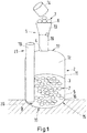
- FIG. 1 shows a disposal device 1 according to the invention, which has a storage tank 2 with a wall 3 and a filling opening 4.
- the wall 3 limits the storage tank 2 to the outside.
- the opening 4, which represents an interruption in the wall 3, is provided with a Filling unit 5 connected.
- organic waste 7 are introduced into the disposal device 1. After entering into the filling unit 5, the organic wastes 7 are collected in the storage tank 2.
- the wall 3 is at least partially embedded in a thermal mass 8.
- a thermal mass 8 in the lower region of the storage tank 2.
- an outer side 9 of the wall 3 of the storage tank 2 has a contact surface 10 with the thermal mass 8.
- an outer side 9 of the wall 3 of at least one side wall 11 of the storage tank is at least partially embedded in the thermal mass.
- the thermal mass 8 earth As a soil thereby any naturally existing, rearranged or introduced soil materials are included.
- the average soil temperature of the soil is about 12 ° C ⁇ 2 ° C, which means that the contents of storage tank 2, the organic waste 7, can be cooled to about 15 to 20 ° C.
- This temperature is the optimal temperature at which the corresponding bacteria can convert the organic wastes 7 to organic acids, primarily acetic acids. The acids formed prevent a further degradation process and reduce the pH in the storage tank to, for example, 4 to 4.5.
- carbon dioxide which is a protective layer 12 above the organic waste 7, is formed. Due to the protective layer 12 made of carbon dioxide, no odor can escape to the outside and no germs or bacteria are formed, which require an aerobic habitat. Other aerobic biology, such as flies and maggots, can not survive or reproduce in the storage tank 2 through the carbon dioxide protective layer 12. Based on the natural cooling by the surrounding soil can be dispensed with an external cooling system.
- the wall 3 of the storage tank 2 consists for example of glass fiber reinforced plastic, which is a fiber-plastic composite of a plastic and glass fibers.
- Thermoplastic plastics such as, for example, polyester resins or epoxy resins, as well as thermoplastics (for example polyamides) are suitable as a basis.
- the filling unit 5 is preferably shaped in the form of a funnel 13, tapering downwards. This allows the filling of organic waste 7 with, for example, a transport vessel 14, without this, should it fall into the hopper 13, in the storage tank. 2 can get.
- the filling opening 4 is arranged in the wall 3 at the top 17 of the storage tank 2.
- the largest possible volume of the storage tank 2 for organic waste 7 is available.
- a central arrangement of the filling opening 4 in the wall 3 at the top 17 of the storage tank 2 is preferred.
- the filling unit 5, between the funnel 13 and the filling opening 4, has a connecting channel 18.
- This one can, as in FIG. 1 shown, run vertically, whereby, for example, the filling height of the filling unit 5 can be varied depending on the structural conditions.
- the connecting channel 18 also other distances can be bridged.
- the storage tank 2 has a suction tube 19. With the help of this suction pipe 19, the storage tank 2 can be emptied by, for example, a pumping vehicle of a service company.
- the suction pipe 19 extends to the bottom 20 of the storage tank so that as much as possible of the organic waste 7 can be sucked.
- the suction tube 19 extends with a free end 21 above ground from the storage tank 2. This allows a good accessibility of the suction tube 19 for service vehicles.
- FIG. 2 a further embodiment of the disposal device 1 is shown.
- the storage tank 2 is substantially completely surrounded by thermal mass 8 and communicates with its wall 3 in direct contact therewith. Only components or at least parts thereof, which should be accessible from outside, such as the filling unit 5 and the suction pipe 19, protrude from the thermal mass 8.
- the conditions of low temperature and acid pH prevent further degradation of the organic material 7, or the organic acids, so that no methane is formed in the storage tank 2.
- the filling unit 5 can be temporarily closed with a cover 22 to the outside.
- the lid 22 rests on the filling opening 6 and closes the disposal device 1 against external environmental influences and protects the carbon dioxide protective layer 12 against turbulence and the storage tank 2 from contamination. Also, a possible unpleasant odor is further reduced.
- the filling unit 5 optionally has a water purification device 23 arranged inside the filling unit 5, which preferably has a nozzle for dispensing and distributing water. It can be operated with cold and / or warm water.
- the water purification device 23 with the nozzle allows the cleaning of a transport container 14, which is used for introducing the organic waste 7.
- the organic waste 7 are protected in the storage tank 2 from drying and kept as liquid as possible. In the storage tank 2 thus creates a mixture 24 of organic waste 7, water and partially degraded residues that can be sucked by a AbpumpGerman.
- an antifreeze 25 may be provided.
- This antifreeze 25 may be, for example, a heating hose which is wound around the water purification device 23.
- the water purification device 23 is controlled by a triggering device 26.
- a triggering device 26 This can be, for example, a contact plate 27 at the knee level. If the contact plate 27 is touched or actuated, water exits from the nozzle of the water purification device 23 for cleaning. Release of the contact plate 27 or a second touch or operation may stop the water discharge of the water purification device 23.
- This contact plate 27 can control the water output of the water purification device 23 by means of a magnetic switch 28.
- This magnetic switch 28 is disposed directly behind the contact plate 27. As long as the contact plate 27 is loaded, the circuit of the magnetic switch 28 is closed and the water purification device 23 is active. If the contact plate is no longer loaded, the water purification device 23 is deactivated.
- An optionally provided supply unit 29, supplies the disposal device 1 with necessary media, for example, water and / or electricity.
- this supply unit 29 has at least one power 30 and / or a water connection 31.
- arrangements of the terminals 30 and 31 are merely exemplary.
- the Supply unit can be arranged directly next to the filling unit, but if necessary also be retrofitted.
- a detailed view of a possible filling unit 5 with supply unit 29 is shown in FIG Fig. 3 shown.
- the water connection 31 supplies the water purification device 23 with water, wherein the fed water can be both cold and warm depending on the customer's request.
- the provision of a power connector 30 allows power to be supplied to the electronic units.
- the electronic units may be, for example, the antifreeze 25, the triggering device 26 for triggering the water purification device 23 or other control units.
- the suction tube 19 may be temporarily closed with a suction tube cover 32. This seals the disposal device 1 to the outside against odor nuisance and protects it against external negative influences.
Landscapes
- Engineering & Computer Science (AREA)
- Mechanical Engineering (AREA)
- Chemical & Material Sciences (AREA)
- Biotechnology (AREA)
- Life Sciences & Earth Sciences (AREA)
- Biochemistry (AREA)
- Health & Medical Sciences (AREA)
- Chemical Kinetics & Catalysis (AREA)
- General Chemical & Material Sciences (AREA)
- Microbiology (AREA)
- Molecular Biology (AREA)
- Organic Chemistry (AREA)
- Processing Of Solid Wastes (AREA)
Claims (9)
- Dispositif d'élimination (1) pour des déchets organiques (7) avec un réservoir de stockage (2) qui présente une paroi (3) et au moins une ouverture (4), dans lequel la paroi (3) délimite vers l'extérieur le réservoir de stockage (2), et dans lequel l'au moins une ouverture (4) est agencée dans la paroi (3), et avec une unité de remplissage (5), dans lequel l'unité de remplissage (5) présente une ouverture de remplissage (6) et est raccordée à l'ouverture (4) dans la paroi (3) du réservoir de stockage (2), la paroi (3) du réservoir de stockage (2) est intégrée au moins par sections dans une masse thermique (8) qui est ou présente de la terre, caractérisé en ce- que l'unité de remplissage (5) qui raccorde l'ouverture de remplissage (6) à l'ouverture (4) dans la paroi (3) du réservoir de stockage (2), est réalisée au moins partiellement en forme d'entonnoir et s'effilant dans le sens d'élimination et présente un couvercle (22) qui ferme vers l'extérieur l'ouverture de remplissage (6),- dans lequel le couvercle présente un bord chevauchant et/ou une garniture,- dans lequel l'unité de remplissage (5) est pourvue d'un dispositif de nettoyage d'eau (23) qui est agencé à une extrémité inférieure de l'entonnoir et présente une buse pour la sortie et la distribution d'eau,- dans lequel la buse débouche dans l'unité de remplissage (5) et- dans lequel le dispositif de nettoyage d'eau (23) présente un dispositif de déclenchement (26) qui est agencé en tant que plaque de contact (27) à l'extérieur sur l'unité de remplissage (5) à hauteur de genou et/ou à hauteur de pied ou est réalisé en tant que plaque de sol.
- Dispositif d'élimination (1) selon la revendication 1, caractérisé en ce que la paroi (3) du réservoir de stockage (2) comporte au moins une paroi latérale (11) et/ou une section de paroi latérale qui est au moins partiellement noyée dans la masse thermique (8).
- Dispositif d'élimination (1) selon l'une quelconque des revendications précédentes, caractérisé en ce que la paroi (3) du réservoir de stockage (2) est intégrée sensiblement complètement dans la masse thermique (8).
- Dispositif d'élimination (1) selon l'une quelconque des revendications précédentes, caractérisé en ce qu'un canal de raccordement (18) est agencé entre l'unité de remplissage (5) et l'ouverture (4) dans la paroi (3) du réservoir de stockage (2).
- Dispositif d'élimination (1) selon la revendication 1, caractérisé en ce que le dispositif de nettoyage d'eau (23) présente une protection contre le gel (25).
- Dispositif d'élimination (1) selon l'une quelconque des revendications précédentes, caractérisé en ce qu'une unité d'alimentation (29) est prévue, laquelle alimente en milieux nécessaires le dispositif d'élimination (1).
- Dispositif d'élimination (1) selon l'une quelconque des revendications 1 ou 5 ou 6, caractérisé en ce que le dispositif de nettoyage d'eau (23) et l'unité d'alimentation (29) forment une unité de construction prémontée, qui peut être montée sur l'unité de remplissage (5) ou le réservoir de stockage (2).
- Dispositif d'élimination (1) selon l'une quelconque des revendications précédentes, caractérisé en ce que le réservoir de stockage (2) présente un tube d'aspiration (19), dans lequel le tube d'aspiration (19) atteint un fond (20) du réservoir de stockage (2) et présente une extrémité libre (21) qui dépasse du réservoir de stockage (2) et est fermée avec un couvercle de tube d'aspiration (32).
- Dispositif d'élimination (1) selon l'une quelconque des revendications précédentes, caractérisé en ce qu'une unité de commande est prévue, laquelle détecte le niveau de remplissage dans le réservoir de stockage (2) et génère à partir de celui-ci un signal de niveau de remplissage et est raccordée à un affichage, dans lequel l'affichage affiche le signal de niveau de remplissage de l'unité de commande.
Applications Claiming Priority (1)
| Application Number | Priority Date | Filing Date | Title |
|---|---|---|---|
| DE102016103078.3A DE102016103078A1 (de) | 2016-02-22 | 2016-02-22 | Entsorgungsvorrichtung |
Publications (2)
| Publication Number | Publication Date |
|---|---|
| EP3210912A1 EP3210912A1 (fr) | 2017-08-30 |
| EP3210912B1 true EP3210912B1 (fr) | 2019-01-02 |
Family
ID=58158862
Family Applications (1)
| Application Number | Title | Priority Date | Filing Date |
|---|---|---|---|
| EP17157336.3A Active EP3210912B1 (fr) | 2016-02-22 | 2017-02-22 | Dispositif d'évacuation |
Country Status (2)
| Country | Link |
|---|---|
| EP (1) | EP3210912B1 (fr) |
| DE (1) | DE102016103078A1 (fr) |
Families Citing this family (1)
| Publication number | Priority date | Publication date | Assignee | Title |
|---|---|---|---|---|
| CN114455226A (zh) * | 2022-02-16 | 2022-05-10 | 西安电子科技大学 | 一种基于物联网nb-iot的高度可调式的医疗废物垃圾桶 |
Family Cites Families (10)
| Publication number | Priority date | Publication date | Assignee | Title |
|---|---|---|---|---|
| FI943759A0 (fi) * | 1994-08-16 | 1994-08-16 | Aate Virtanen | Foerfarande foer att behandla organogeniska avfall och en i foerfarandet anvaendbar anordning |
| DE19524629C1 (de) * | 1995-07-06 | 1997-02-13 | Helbing & Partner | Stationäre Bioabfallsammelanlage |
| US5568996A (en) * | 1995-07-11 | 1996-10-29 | Organic Resource Management Inc. | Storage and disposal of organic waste |
| FR2784315B1 (fr) | 1998-10-09 | 2000-12-29 | Bonnet Cidelcem Grande Cuisine | Ensemble d'essorage et de compactage de dechets alimentaires |
| DE10202181A1 (de) | 2002-01-22 | 2003-08-07 | Elisabeth Schneider | Mülltonne und ein Aufsatz für eine Mülltonne |
| DE202004017405U1 (de) * | 2004-11-09 | 2005-01-27 | Siegel, Natalia | Unterflurmüllsammelbehälter |
| DE202005006468U1 (de) * | 2005-04-22 | 2006-08-24 | Pöttinger Entsorgungstechnik GmbH & Co. KG | Müllsammelvorrichtung |
| FR2949107B1 (fr) * | 2009-08-11 | 2013-05-31 | Plastic Omnium Cie | Dispositif pour accueillir un conteneur de collecte de dechets au moins partiellement enterre |
| BR112012010375A2 (pt) * | 2009-11-03 | 2019-09-24 | Langston Jody | aparelho, sistema e método implementado por máquina |
| CN105154475A (zh) * | 2015-10-20 | 2015-12-16 | 北京国能中电能源有限责任公司 | 一种餐厨垃圾厌氧发酵产沼气的快速启动方法及装置 |
-
2016
- 2016-02-22 DE DE102016103078.3A patent/DE102016103078A1/de not_active Ceased
-
2017
- 2017-02-22 EP EP17157336.3A patent/EP3210912B1/fr active Active
Non-Patent Citations (1)
| Title |
|---|
| None * |
Also Published As
| Publication number | Publication date |
|---|---|
| DE102016103078A1 (de) | 2017-08-24 |
| EP3210912A1 (fr) | 2017-08-30 |
Similar Documents
| Publication | Publication Date | Title |
|---|---|---|
| JP4085060B2 (ja) | 堆肥製造装置と方法 | |
| KR102434316B1 (ko) | 휴대용 재생 에너지 자가 발전 시스템을 위한 염 관리 시스템 | |
| WO2009094738A2 (fr) | Système d'élimination finale de déchets par compactage et ensachage | |
| DE202010013818U1 (de) | Schleusenkammerbehälter mit integrierter Pressvorrichtung und Müllsammelvorrichtung | |
| EP2569102A2 (fr) | Procédé et système de traitement à froid de déchets solides municipaux | |
| EP0476217A1 (fr) | Dispositif de valorisation de matière organique | |
| US10464745B2 (en) | Modular waste transfer station (MWTS) | |
| EP3210912B1 (fr) | Dispositif d'évacuation | |
| DE69912582T2 (de) | Verfahren und zugehörige anlagen zur behandlung und entsorgung von müll | |
| DE102007036049A1 (de) | Verfahren und Vorrichtung zur Verarbeitung, insbesondere Vergärung, von Biomasse unter Bildung von Biogas | |
| KR200233113Y1 (ko) | 이동식 발효 장치 | |
| KR102880236B1 (ko) | 생활쓰레기 처리 시스템 | |
| KR100398624B1 (ko) | 이동식 발효 장치 | |
| DE2542999A1 (de) | Muellablagerungsanlage | |
| AT391636B (de) | Verfahren zur sanierung von altlast-abfalldeponien | |
| AU740172B2 (en) | The SBS mass treatment system | |
| WO1994002262A1 (fr) | Installation de depot de dechets | |
| DE4334498A1 (de) | Verfahren zum Kompostieren organischer Abfälle | |
| CH697135A5 (fr) | Installation de fermentation avec un dispositif pour charger des matériaux | |
| WO1993012017A2 (fr) | Procede et dispositif d'elimination de dechets | |
| DE69414341T2 (de) | Verfahren zur Bearbeitung von festen Abfällen durch Kompaktierung und Verpacken | |
| DE102014113681B4 (de) | Belüftung von Rundsilos für Schüttgüter | |
| EP1493689A1 (fr) | Dispositif mobil pour le ramassage, pour la homogénésiation et pour le broyage des déchets | |
| DE2354186A1 (de) | Aufbereitung von abfallstoffen fuer die ablagerung | |
| DE20315381U1 (de) | Fahrbare und dezentral arbeitende Kompostieranlage in Container zum Sammeln und schnellen Kompostieren organischer Abfälle nebst Logistikzubehör |
Legal Events
| Date | Code | Title | Description |
|---|---|---|---|
| PUAI | Public reference made under article 153(3) epc to a published international application that has entered the european phase |
Free format text: ORIGINAL CODE: 0009012 |
|
| STAA | Information on the status of an ep patent application or granted ep patent |
Free format text: STATUS: THE APPLICATION HAS BEEN PUBLISHED |
|
| AK | Designated contracting states |
Kind code of ref document: A1 Designated state(s): AL AT BE BG CH CY CZ DE DK EE ES FI FR GB GR HR HU IE IS IT LI LT LU LV MC MK MT NL NO PL PT RO RS SE SI SK SM TR |
|
| AX | Request for extension of the european patent |
Extension state: BA ME |
|
| STAA | Information on the status of an ep patent application or granted ep patent |
Free format text: STATUS: REQUEST FOR EXAMINATION WAS MADE |
|
| 17P | Request for examination filed |
Effective date: 20180227 |
|
| RBV | Designated contracting states (corrected) |
Designated state(s): AL AT BE BG CH CY CZ DE DK EE ES FI FR GB GR HR HU IE IS IT LI LT LU LV MC MK MT NL NO PL PT RO RS SE SI SK SM TR |
|
| STAA | Information on the status of an ep patent application or granted ep patent |
Free format text: STATUS: EXAMINATION IS IN PROGRESS |
|
| 17Q | First examination report despatched |
Effective date: 20180508 |
|
| REG | Reference to a national code |
Ref country code: DE Ref legal event code: R079 Ref document number: 502017000583 Country of ref document: DE Free format text: PREVIOUS MAIN CLASS: B65F0001100000 Ipc: C05F0017020000 |
|
| GRAP | Despatch of communication of intention to grant a patent |
Free format text: ORIGINAL CODE: EPIDOSNIGR1 |
|
| STAA | Information on the status of an ep patent application or granted ep patent |
Free format text: STATUS: GRANT OF PATENT IS INTENDED |
|
| RIC1 | Information provided on ipc code assigned before grant |
Ipc: B65F 1/12 20060101ALI20180607BHEP Ipc: B65F 1/10 20060101ALI20180607BHEP Ipc: B65F 7/00 20060101ALI20180607BHEP Ipc: B65F 1/14 20060101ALI20180607BHEP Ipc: C05F 17/02 20060101AFI20180607BHEP |
|
| INTG | Intention to grant announced |
Effective date: 20180625 |
|
| GRAS | Grant fee paid |
Free format text: ORIGINAL CODE: EPIDOSNIGR3 |
|
| GRAJ | Information related to disapproval of communication of intention to grant by the applicant or resumption of examination proceedings by the epo deleted |
Free format text: ORIGINAL CODE: EPIDOSDIGR1 |
|
| GRAL | Information related to payment of fee for publishing/printing deleted |
Free format text: ORIGINAL CODE: EPIDOSDIGR3 |
|
| STAA | Information on the status of an ep patent application or granted ep patent |
Free format text: STATUS: EXAMINATION IS IN PROGRESS |
|
| GRAR | Information related to intention to grant a patent recorded |
Free format text: ORIGINAL CODE: EPIDOSNIGR71 |
|
| STAA | Information on the status of an ep patent application or granted ep patent |
Free format text: STATUS: GRANT OF PATENT IS INTENDED |
|
| GRAA | (expected) grant |
Free format text: ORIGINAL CODE: 0009210 |
|
| STAA | Information on the status of an ep patent application or granted ep patent |
Free format text: STATUS: THE PATENT HAS BEEN GRANTED |
|
| INTC | Intention to grant announced (deleted) | ||
| AK | Designated contracting states |
Kind code of ref document: B1 Designated state(s): AL AT BE BG CH CY CZ DE DK EE ES FI FR GB GR HR HU IE IS IT LI LT LU LV MC MK MT NL NO PL PT RO RS SE SI SK SM TR |
|
| INTG | Intention to grant announced |
Effective date: 20181123 |
|
| REG | Reference to a national code |
Ref country code: GB Ref legal event code: FG4D Free format text: NOT ENGLISH |
|
| REG | Reference to a national code |
Ref country code: CH Ref legal event code: EP Ref country code: AT Ref legal event code: REF Ref document number: 1084168 Country of ref document: AT Kind code of ref document: T Effective date: 20190115 |
|
| REG | Reference to a national code |
Ref country code: IE Ref legal event code: FG4D Free format text: LANGUAGE OF EP DOCUMENT: GERMAN |
|
| REG | Reference to a national code |
Ref country code: DE Ref legal event code: R096 Ref document number: 502017000583 Country of ref document: DE |
|
| REG | Reference to a national code |
Ref country code: CH Ref legal event code: NV Representative=s name: ISLER AND PEDRAZZINI AG, CH |
|
| REG | Reference to a national code |
Ref country code: NL Ref legal event code: FP |
|
| REG | Reference to a national code |
Ref country code: LT Ref legal event code: MG4D |
|
| PG25 | Lapsed in a contracting state [announced via postgrant information from national office to epo] |
Ref country code: NO Free format text: LAPSE BECAUSE OF FAILURE TO SUBMIT A TRANSLATION OF THE DESCRIPTION OR TO PAY THE FEE WITHIN THE PRESCRIBED TIME-LIMIT Effective date: 20190402 Ref country code: PL Free format text: LAPSE BECAUSE OF FAILURE TO SUBMIT A TRANSLATION OF THE DESCRIPTION OR TO PAY THE FEE WITHIN THE PRESCRIBED TIME-LIMIT Effective date: 20190102 Ref country code: LT Free format text: LAPSE BECAUSE OF FAILURE TO SUBMIT A TRANSLATION OF THE DESCRIPTION OR TO PAY THE FEE WITHIN THE PRESCRIBED TIME-LIMIT Effective date: 20190102 Ref country code: ES Free format text: LAPSE BECAUSE OF FAILURE TO SUBMIT A TRANSLATION OF THE DESCRIPTION OR TO PAY THE FEE WITHIN THE PRESCRIBED TIME-LIMIT Effective date: 20190102 Ref country code: PT Free format text: LAPSE BECAUSE OF FAILURE TO SUBMIT A TRANSLATION OF THE DESCRIPTION OR TO PAY THE FEE WITHIN THE PRESCRIBED TIME-LIMIT Effective date: 20190502 Ref country code: SE Free format text: LAPSE BECAUSE OF FAILURE TO SUBMIT A TRANSLATION OF THE DESCRIPTION OR TO PAY THE FEE WITHIN THE PRESCRIBED TIME-LIMIT Effective date: 20190102 Ref country code: FI Free format text: LAPSE BECAUSE OF FAILURE TO SUBMIT A TRANSLATION OF THE DESCRIPTION OR TO PAY THE FEE WITHIN THE PRESCRIBED TIME-LIMIT Effective date: 20190102 |
|
| PG25 | Lapsed in a contracting state [announced via postgrant information from national office to epo] |
Ref country code: LV Free format text: LAPSE BECAUSE OF FAILURE TO SUBMIT A TRANSLATION OF THE DESCRIPTION OR TO PAY THE FEE WITHIN THE PRESCRIBED TIME-LIMIT Effective date: 20190102 Ref country code: RS Free format text: LAPSE BECAUSE OF FAILURE TO SUBMIT A TRANSLATION OF THE DESCRIPTION OR TO PAY THE FEE WITHIN THE PRESCRIBED TIME-LIMIT Effective date: 20190102 Ref country code: IS Free format text: LAPSE BECAUSE OF FAILURE TO SUBMIT A TRANSLATION OF THE DESCRIPTION OR TO PAY THE FEE WITHIN THE PRESCRIBED TIME-LIMIT Effective date: 20190502 Ref country code: BG Free format text: LAPSE BECAUSE OF FAILURE TO SUBMIT A TRANSLATION OF THE DESCRIPTION OR TO PAY THE FEE WITHIN THE PRESCRIBED TIME-LIMIT Effective date: 20190402 Ref country code: GR Free format text: LAPSE BECAUSE OF FAILURE TO SUBMIT A TRANSLATION OF THE DESCRIPTION OR TO PAY THE FEE WITHIN THE PRESCRIBED TIME-LIMIT Effective date: 20190403 Ref country code: HR Free format text: LAPSE BECAUSE OF FAILURE TO SUBMIT A TRANSLATION OF THE DESCRIPTION OR TO PAY THE FEE WITHIN THE PRESCRIBED TIME-LIMIT Effective date: 20190102 |
|
| REG | Reference to a national code |
Ref country code: DE Ref legal event code: R097 Ref document number: 502017000583 Country of ref document: DE |
|
| PG25 | Lapsed in a contracting state [announced via postgrant information from national office to epo] |
Ref country code: DK Free format text: LAPSE BECAUSE OF FAILURE TO SUBMIT A TRANSLATION OF THE DESCRIPTION OR TO PAY THE FEE WITHIN THE PRESCRIBED TIME-LIMIT Effective date: 20190102 Ref country code: AL Free format text: LAPSE BECAUSE OF FAILURE TO SUBMIT A TRANSLATION OF THE DESCRIPTION OR TO PAY THE FEE WITHIN THE PRESCRIBED TIME-LIMIT Effective date: 20190102 Ref country code: RO Free format text: LAPSE BECAUSE OF FAILURE TO SUBMIT A TRANSLATION OF THE DESCRIPTION OR TO PAY THE FEE WITHIN THE PRESCRIBED TIME-LIMIT Effective date: 20190102 Ref country code: IT Free format text: LAPSE BECAUSE OF FAILURE TO SUBMIT A TRANSLATION OF THE DESCRIPTION OR TO PAY THE FEE WITHIN THE PRESCRIBED TIME-LIMIT Effective date: 20190102 Ref country code: SK Free format text: LAPSE BECAUSE OF FAILURE TO SUBMIT A TRANSLATION OF THE DESCRIPTION OR TO PAY THE FEE WITHIN THE PRESCRIBED TIME-LIMIT Effective date: 20190102 Ref country code: CZ Free format text: LAPSE BECAUSE OF FAILURE TO SUBMIT A TRANSLATION OF THE DESCRIPTION OR TO PAY THE FEE WITHIN THE PRESCRIBED TIME-LIMIT Effective date: 20190102 Ref country code: EE Free format text: LAPSE BECAUSE OF FAILURE TO SUBMIT A TRANSLATION OF THE DESCRIPTION OR TO PAY THE FEE WITHIN THE PRESCRIBED TIME-LIMIT Effective date: 20190102 |
|
| PLBE | No opposition filed within time limit |
Free format text: ORIGINAL CODE: 0009261 |
|
| STAA | Information on the status of an ep patent application or granted ep patent |
Free format text: STATUS: NO OPPOSITION FILED WITHIN TIME LIMIT |
|
| REG | Reference to a national code |
Ref country code: DE Ref legal event code: R079 Ref document number: 502017000583 Country of ref document: DE Free format text: PREVIOUS MAIN CLASS: C05F0017020000 Ipc: C05F0017900000 |
|
| PG25 | Lapsed in a contracting state [announced via postgrant information from national office to epo] |
Ref country code: SM Free format text: LAPSE BECAUSE OF FAILURE TO SUBMIT A TRANSLATION OF THE DESCRIPTION OR TO PAY THE FEE WITHIN THE PRESCRIBED TIME-LIMIT Effective date: 20190102 |
|
| 26N | No opposition filed |
Effective date: 20191003 |
|
| PG25 | Lapsed in a contracting state [announced via postgrant information from national office to epo] |
Ref country code: SI Free format text: LAPSE BECAUSE OF FAILURE TO SUBMIT A TRANSLATION OF THE DESCRIPTION OR TO PAY THE FEE WITHIN THE PRESCRIBED TIME-LIMIT Effective date: 20190102 |
|
| PG25 | Lapsed in a contracting state [announced via postgrant information from national office to epo] |
Ref country code: TR Free format text: LAPSE BECAUSE OF FAILURE TO SUBMIT A TRANSLATION OF THE DESCRIPTION OR TO PAY THE FEE WITHIN THE PRESCRIBED TIME-LIMIT Effective date: 20190102 |
|
| PG25 | Lapsed in a contracting state [announced via postgrant information from national office to epo] |
Ref country code: MT Free format text: LAPSE BECAUSE OF FAILURE TO SUBMIT A TRANSLATION OF THE DESCRIPTION OR TO PAY THE FEE WITHIN THE PRESCRIBED TIME-LIMIT Effective date: 20190102 |
|
| PG25 | Lapsed in a contracting state [announced via postgrant information from national office to epo] |
Ref country code: CY Free format text: LAPSE BECAUSE OF FAILURE TO SUBMIT A TRANSLATION OF THE DESCRIPTION OR TO PAY THE FEE WITHIN THE PRESCRIBED TIME-LIMIT Effective date: 20190102 |
|
| PG25 | Lapsed in a contracting state [announced via postgrant information from national office to epo] |
Ref country code: HU Free format text: LAPSE BECAUSE OF FAILURE TO SUBMIT A TRANSLATION OF THE DESCRIPTION OR TO PAY THE FEE WITHIN THE PRESCRIBED TIME-LIMIT; INVALID AB INITIO Effective date: 20170222 |
|
| PG25 | Lapsed in a contracting state [announced via postgrant information from national office to epo] |
Ref country code: MK Free format text: LAPSE BECAUSE OF FAILURE TO SUBMIT A TRANSLATION OF THE DESCRIPTION OR TO PAY THE FEE WITHIN THE PRESCRIBED TIME-LIMIT Effective date: 20190102 |
|
| PGFP | Annual fee paid to national office [announced via postgrant information from national office to epo] |
Ref country code: CH Payment date: 20250305 Year of fee payment: 9 |
|
| REG | Reference to a national code |
Ref country code: CH Ref legal event code: U11 Free format text: ST27 STATUS EVENT CODE: U-0-0-U10-U11 (AS PROVIDED BY THE NATIONAL OFFICE) Effective date: 20260303 |
|
| PGFP | Annual fee paid to national office [announced via postgrant information from national office to epo] |
Ref country code: LU Payment date: 20260227 Year of fee payment: 10 Ref country code: NL Payment date: 20260227 Year of fee payment: 10 |
|
| PGFP | Annual fee paid to national office [announced via postgrant information from national office to epo] |
Ref country code: GB Payment date: 20260227 Year of fee payment: 10 |
|
| PGFP | Annual fee paid to national office [announced via postgrant information from national office to epo] |
Ref country code: MC Payment date: 20260220 Year of fee payment: 10 |
|
| PGFP | Annual fee paid to national office [announced via postgrant information from national office to epo] |
Ref country code: DE Payment date: 20260228 Year of fee payment: 10 Ref country code: IE Payment date: 20260227 Year of fee payment: 10 |
|
| PGFP | Annual fee paid to national office [announced via postgrant information from national office to epo] |
Ref country code: AT Payment date: 20260302 Year of fee payment: 10 |
|
| PGFP | Annual fee paid to national office [announced via postgrant information from national office to epo] |
Ref country code: BE Payment date: 20260227 Year of fee payment: 10 |
|
| PGFP | Annual fee paid to national office [announced via postgrant information from national office to epo] |
Ref country code: FR Payment date: 20260227 Year of fee payment: 10 |