EP3210917A1 - Stockage vertical avec moyens de levage pour marchandises - Google Patents
Stockage vertical avec moyens de levage pour marchandises Download PDFInfo
- Publication number
- EP3210917A1 EP3210917A1 EP16157180.7A EP16157180A EP3210917A1 EP 3210917 A1 EP3210917 A1 EP 3210917A1 EP 16157180 A EP16157180 A EP 16157180A EP 3210917 A1 EP3210917 A1 EP 3210917A1
- Authority
- EP
- European Patent Office
- Prior art keywords
- goods
- vertical
- lifting
- elements
- transport direction
- Prior art date
- Legal status (The legal status is an assumption and is not a legal conclusion. Google has not performed a legal analysis and makes no representation as to the accuracy of the status listed.)
- Withdrawn
Links
- 230000005540 biological transmission Effects 0.000 description 7
- 239000000969 carrier Substances 0.000 description 4
- 235000001674 Agaricus brunnescens Nutrition 0.000 description 1
- 230000001174 ascending effect Effects 0.000 description 1
- 238000007726 management method Methods 0.000 description 1
- 238000000034 method Methods 0.000 description 1
- 238000004806 packaging method and process Methods 0.000 description 1
- 230000000284 resting effect Effects 0.000 description 1
- 238000005070 sampling Methods 0.000 description 1
Images



Classifications
-
- B—PERFORMING OPERATIONS; TRANSPORTING
- B65—CONVEYING; PACKING; STORING; HANDLING THIN OR FILAMENTARY MATERIAL
- B65G—TRANSPORT OR STORAGE DEVICES, e.g. CONVEYORS FOR LOADING OR TIPPING, SHOP CONVEYOR SYSTEMS OR PNEUMATIC TUBE CONVEYORS
- B65G47/00—Article or material-handling devices associated with conveyors; Methods employing such devices
- B65G47/34—Devices for discharging articles or materials from conveyor
- B65G47/46—Devices for discharging articles or materials from conveyor and distributing, e.g. automatically, to desired points
- B65G47/51—Devices for discharging articles or materials from conveyor and distributing, e.g. automatically, to desired points according to unprogrammed signals, e.g. influenced by supply situation at destination
- B65G47/5104—Devices for discharging articles or materials from conveyor and distributing, e.g. automatically, to desired points according to unprogrammed signals, e.g. influenced by supply situation at destination for articles
- B65G47/515—First In-Last Out systems [FILO]; Last In-First Out systems [LIFO]
- B65G47/5181—First In-Last Out systems [FILO]; Last In-First Out systems [LIFO] using stacking or destacking arrangements or stacks of articles or article-carriers
-
- B—PERFORMING OPERATIONS; TRANSPORTING
- B65—CONVEYING; PACKING; STORING; HANDLING THIN OR FILAMENTARY MATERIAL
- B65G—TRANSPORT OR STORAGE DEVICES, e.g. CONVEYORS FOR LOADING OR TIPPING, SHOP CONVEYOR SYSTEMS OR PNEUMATIC TUBE CONVEYORS
- B65G47/00—Article or material-handling devices associated with conveyors; Methods employing such devices
- B65G47/34—Devices for discharging articles or materials from conveyor
- B65G47/46—Devices for discharging articles or materials from conveyor and distributing, e.g. automatically, to desired points
- B65G47/51—Devices for discharging articles or materials from conveyor and distributing, e.g. automatically, to desired points according to unprogrammed signals, e.g. influenced by supply situation at destination
- B65G47/5104—Devices for discharging articles or materials from conveyor and distributing, e.g. automatically, to desired points according to unprogrammed signals, e.g. influenced by supply situation at destination for articles
- B65G47/515—First In-Last Out systems [FILO]; Last In-First Out systems [LIFO]
- B65G47/5154—First In-Last Out systems [FILO]; Last In-First Out systems [LIFO] using endless conveyors
-
- B—PERFORMING OPERATIONS; TRANSPORTING
- B65—CONVEYING; PACKING; STORING; HANDLING THIN OR FILAMENTARY MATERIAL
- B65G—TRANSPORT OR STORAGE DEVICES, e.g. CONVEYORS FOR LOADING OR TIPPING, SHOP CONVEYOR SYSTEMS OR PNEUMATIC TUBE CONVEYORS
- B65G1/00—Storing articles, individually or in orderly arrangement, in warehouses or magazines
- B65G1/02—Storage devices
- B65G1/04—Storage devices mechanical
- B65G1/12—Storage devices mechanical with separate article supports or holders movable in a closed circuit to facilitate insertion or removal of articles the articles being books, documents, forms or the like
- B65G1/127—Storage devices mechanical with separate article supports or holders movable in a closed circuit to facilitate insertion or removal of articles the articles being books, documents, forms or the like the circuit being confined in a vertical plane
Definitions
- the invention relates to a vertical warehouse for goods according to the preamble of patent claim 1.
- a device of the type mentioned is from the European patent application EP2450295A1 entitled "vertical storage for containers and arrangement comprising a shelf and a vertical storage" has become known.
- a support body In a support body a plurality of superposed receptacles are arranged, which are movable by a drive in height through the support body. In the lower end position of the container receptacles these form a resting on the floor stack. In operation, the uppermost stack in the stack is lifted by a driver arranged on the drive. The vertical distance of the receptacles and thus the maximum height of the container is determined by the mutual distance of the driver.
- a problem to be solved by the invention is, according to the document, to increase the capacity during storage or retrieval of containers in a rack, in particular a high rack, and at the same time to significantly reduce the costs.
- an object of the invention is to propose a vertical bearing in which the space for each product is adaptable to its vertical dimension.
- the space in the frame can be utilized to the maximum.
- the vertical distances of the lifting elements can be kept relatively low, so that for a given Rack height find many goods with a low height space. For the storage of goods with a greater height, the existing next to these goods lifting elements remain empty.
- Another object of the invention is to provide a bearing assembly which allows to carry out many simultaneous sorting processes and in which the space for the goods can also be adjusted in the horizontal direction.
- FIGS. 1 to 4 illustrate a first embodiment of an inventive vertical bearing 1.
- a supply support 2 for the goods is equipped with support elements 3, which in this example have the form of rolls on which the goods are applied in a horizontal transport direction 4, and at least one of which is drivable ,
- a plurality of lifting elements 6 is arranged, which are fixedly connected to rotating traction means 9 and movable with these in a vertical transport direction 10.
- the lifting elements 6 have in this embodiment, the form of an arranged on an axis 7, rotatable roller 8 (see FIG. 2 ), but may also be designed differently, for example as a carrier with any cross-section, as simple, rigid pins, pin-like with a mushroom shape or as a hook.
- the lifting elements 6 between two support members 3 in the vertical transport direction 10 are movable therethrough.
- the support elements 3 designed as rollers are hereby combined into groups by means of lateral supports.
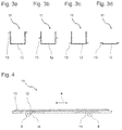
- the goods not shown here are arranged on goods carriers 11, for example, as in the FIGS. 3 and 4 can be shown formed.
- the article carrier 11 comprises a carrier body 12, which may be formed like an open or closed box, a tray or a flat tray, wherein the width of this carrier body 12 fits between the lifting elements 6, when the goods carrier 11 in the horizontal transport direction 4 in the Vertical bearing 1 is retracted.
- a respective rib 13 is arranged, which engages when entering the vertical bearing 1 between two superimposed lifting elements 6, so that when booting the lifting elements 6 of the goods carrier 11 is lifted by this.
- the goods carrier 11 has the shape of a tray, the total width extends to between the lifting elements 6.
- the execution as a tray has the advantage that the minimum vertical distance of the goods in the vertical storage 1 by the height of the goods and not by the height of the goods carrier 11 is determined.
- the product carrier has 11 recesses 14 which rest upon lifting on the rollers 8 and thus stabilize the goods carrier 11 in the horizontal direction in its position. Such depressions may be arranged on the tray in the bottom of the tray or on all types of goods carriers on the described ribs 12.
- FIGS. 5 to 12 described embodiment of the vertical bearing 1 differs from the above-described embodiment, in particular by the fact that can be dispensed with specially designed goods carrier, although if required, here as well, such as pallets or containers can be used, which are not specifically designed for use in the inventive vertical bearing must and thus have no ribs 13.
- lifting elements 19 which are selectively movable into and out of the transport path of the goods or goods carriers, as will be described in detail below.
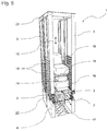
- FIG. 5 are two in the horizontal direction of transport arranged one behind the other vertical bearing 1 can be seen.
- goods 16 are located.
- the delivery support 2 also has support elements 3 designed as rollers in this example, a support 17 being provided for a number of support elements 3 in each case.
- Traction means 9 which are arranged endlessly circulating over lower pulleys 22 and upper pulleys 23 and to which the lifting elements 19 are attached at regular intervals.
- a number of juxtaposed lifting elements 19 is pivotally arranged in a cassette-like lifting element unit 18, which in turn is connected to the traction means 9.
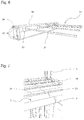
- FIG. 6 shows in a perspective view a Hubelement unit 18 with - in this example - four arranged therein lifting elements 19.
- Each lifting element 19 is composed of a vertically arranged in the Hubelement unit 18 axis 20 and projecting from this axis boom 21.
- the boom 21 are shown here relatively long, so that they would hinder each other when swinging into the Hubelement unit 18. Measures to prevent this are discussed below in connection with the FIGS. 9 to 11 described. But the boom 21 can also be designed much shorter than, for example, in FIG. 6 shown. This can be used, for example, to lift pallets or containers.
- rollers not shown may be arranged, similar to the example according to FIG. 2 ,
- a connecting pin designated 24 is for connection to a Traction means 9 forming chain determined and guide rollers 25 serve to guide the Hubelement unit 18 during their up and down movements in the frame fifth
- FIG. 7 shows in one opposite FIG. 5 In this position, a product 16 can be introduced in the horizontal transport direction 4 and then by means of the boom 21st Exaggerated scale a section of the supply carrier 2 with the support elements 3. Well visible are the projecting between the rollers designed as supporting elements 3 boom 21 of the lifting elements be raised in a storage position. The same position of the boom 21 is of course also taken after a product 16 has been deposited by the boom 21 on the delivery support 2 and then transported away in the horizontal transport direction 4.
- FIG. 8 shows in perspective an enlarged section of the lower portion of the vertical bearing 1 according FIG. 5 ,
- the traction means 9 is formed here as a chain shown schematically.
- a lifting element unit 18 is mounted with its connecting pin 24 on a chain link of the traction means 9.
- the guide rollers 25 of the lifting element unit 18 are guided in guide rail 26, which have an inlet aid 27 at its lower end and prevent the tilting of the lifting elements in the goods receiving.
- the mechanism includes a drive unit 30, which may be formed for example as a pneumatic or hydraulic piston-cylinder unit or as a Hubspindelgetriebe and is connected to an actuating linkage 31, which in turn is translationally movable in a guide 32.
- actuating linkage 31 On the actuating linkage 31 actuating pin 33 are arranged, each with a arranged in the Hubelement unit 18 transmission rod 34 (see Figures 9 and 10 ) interact.
- the lifting element unit 18 is shown with pivoted or pivoted arms 21, wherein in the figures parts are omitted, which would hide the view of the elements to be described.
- the axes 20 of the lifting elements 19 are each provided with an arm 36 for rotating the axle and thus pivoting the boom 21.
- An arranged on the mentioned transmission rod 34 pin 35 engages in a slot of the arm 36 a.
- two transmission rods 34 are present, wherein the upper in the figure transmission rod 34 is operatively connected to the two in the figure right lifting elements, whereas the lower in the figure transmission rod 34 is operatively connected to the two left in the figure arranged lifting elements.
- the two transmission rods 34 are coupled by a two-armed lever 37 so that they move in opposite directions when actuated.
- FIG. 10 also shows that the boom 21 are offset in height when swung in, so they do not interfere with each other in their pivotal movement.
- FIG. 11 The axis 20 has a projecting from her cam 39 and is rotatably mounted in a stationary sleeve 38. When swinging the boom 21, the cam 39 slides on a sleeve 40 disposed on the curve and raises the axis 20 together with the boom 21 at. So come in the presentation FIG. 10 the two arranged on the left boom 21 inußschwenktem state above the two right boom 21 to lie.
- all four arms 21 are in the swung-out position according to FIG. 9 in a common plane.
- lifting elements 19 it is possible to arrange lifting elements 19 only on one side of the supply carrier 2, which lift the goods 16 in the manner of a forklift.
- FIG. 12 shows a perspective section of the vertical bearing 1 according to FIG. 5 ,
- the delivery carrier 2 is integrated here in the frame 5, wherein two support elements 3 designed as rollers are combined by lateral plates.
- one of the traction means 9 and a lower guide roller 22 is visible.
- the mentioned drive unit 30 for the pivotable lifting elements 18 and a motor 41 which drives the traction means 9 via a shaft 42 and a belt 43.
- a vertical bearing 1 of the type described above is preferably operated automatically by a control device, not shown, as described below.
- a control device for loading the vertical bearing 1, an article 16, possibly located on a goods carrier 11, is transported in the horizontal transport direction 4 to a delivery position on the delivery carrier 2.
- This transport can be performed by a subsequent to the delivery support 2 conveyor such as a conveyor belt or a roller conveyor.
- the delivery support 2 may be formed so long that it forms the means of transport and protrudes in the horizontal transport direction 4 on one, preferably on both sides of the vertical bearing 1.
- the lifting elements 19 are swung out either below or above the support elements 3 and then brought in the vertical transport direction 10 in a height position just below the support surface formed by the support elements.
- the product 16 or the goods carrier 11 is lifted by the lifting elements 6 and 19 as far as it requires the height of the following goods.
- the height of the goods lying ready on the means of transport is detected by measuring means, not shown, and transmitted to the control device. By this measure, the goods are stored one above the other with minimal vertical space loss and the overall height of the vertical bearing can be optimally utilized.
- the lifting elements 6, 19 lowered so far until the goods or the goods carrier rests on the delivery support. Subsequently, the goods in the horizontal transport direction 4 out of the vertical bearing 1 and the optionally pivotable lifting elements 19 are brought into a position below or above the support members 3 and pivoted. If the vertical storage a specific, stored goods are removed, under which other goods are, these other goods must be outsourced first. In simple cases, these outsourced but currently not required goods can be stored on a means of transport on one side of the vertical warehouse or in another vertical warehouse, while said certain goods led out of the vertical warehouse and a sampling point, for example, a packaging station is supplied. Thereafter, the intermediately stored goods are stored again in the manner described.
- any number of vertical bearings can be arranged in rows one behind the other and rows next to each other be arranged, the rows are connected by appropriate means of transport for the goods. In each vertical storage a series then the last stored goods must be raised so far that other goods in the horizontal direction of transport 4 through the vertical warehouse, for example, can be transported to another vertical warehouse or a removal point.
- bearing assembly which allows a flexible adjustment of the storage space in height and length, as mentioned, can be responded to changing needs in the storage logistics without additional investment.
- the same bearing arrangement can be used both for example for containers, pallets and small parts as well as for oversizes. There are no special requirements for the building, such as leveling the floor slab, as would be necessary, for example, for the use of stacker cranes.
- the bearing assembly can also be used in buildings with different room heights.
- the bearing assembly allows optimal use of space given, in particular lanes for storage and retrieval equipment and traffic areas for forklifts and pedestrians omitted.
Landscapes
- Engineering & Computer Science (AREA)
- Mechanical Engineering (AREA)
- Warehouses Or Storage Devices (AREA)
Priority Applications (2)
| Application Number | Priority Date | Filing Date | Title |
|---|---|---|---|
| EP16157180.7A EP3210917A1 (fr) | 2016-02-24 | 2016-02-24 | Stockage vertical avec moyens de levage pour marchandises |
| PCT/EP2017/053147 WO2017144296A1 (fr) | 2016-02-24 | 2017-02-13 | Dispositif de stockage vertical pour marchandises |
Applications Claiming Priority (1)
| Application Number | Priority Date | Filing Date | Title |
|---|---|---|---|
| EP16157180.7A EP3210917A1 (fr) | 2016-02-24 | 2016-02-24 | Stockage vertical avec moyens de levage pour marchandises |
Publications (1)
| Publication Number | Publication Date |
|---|---|
| EP3210917A1 true EP3210917A1 (fr) | 2017-08-30 |
Family
ID=55446651
Family Applications (1)
| Application Number | Title | Priority Date | Filing Date |
|---|---|---|---|
| EP16157180.7A Withdrawn EP3210917A1 (fr) | 2016-02-24 | 2016-02-24 | Stockage vertical avec moyens de levage pour marchandises |
Country Status (2)
| Country | Link |
|---|---|
| EP (1) | EP3210917A1 (fr) |
| WO (1) | WO2017144296A1 (fr) |
Cited By (4)
| Publication number | Priority date | Publication date | Assignee | Title |
|---|---|---|---|---|
| FR3081454A1 (fr) * | 2018-05-24 | 2019-11-29 | Sg2C | Installation de regulation de flux de produits |
| WO2019224459A3 (fr) * | 2018-05-24 | 2020-01-30 | Sg2C | Installation de regulation de flux de produits |
| DE102019111709A1 (de) * | 2019-05-06 | 2020-11-12 | Dematic Gmbh | Lagersystem zum Lagern von Waren in einem dreidimensionalen Lager |
| CN113859837A (zh) * | 2021-10-20 | 2021-12-31 | 成都航空职业技术学院 | 一种立面运载装置及自动式多任务存取系统 |
Citations (10)
| Publication number | Priority date | Publication date | Assignee | Title |
|---|---|---|---|---|
| DE1136275B (de) * | 1961-08-30 | 1962-09-06 | Stahl R Fa | Speichereinrichtung an Be- und Entladestellen von Behaelterfoerderanlagen |
| DE2352990A1 (de) * | 1973-10-23 | 1975-04-30 | Philipp Lemke | Lagerstaender mit paternosterwirkung |
| EP0025776A1 (fr) * | 1979-09-14 | 1981-03-25 | ITALTRACTOR I.T.M. S.p.A. | Dispositif pour l'emmagasinage d'objets, notamment pour des maillons de chenilles |
| US4718536A (en) * | 1986-10-15 | 1988-01-12 | Toby Enterprises | Stack storage elevator for sliced, stacked comestible products |
| DE3937776A1 (de) * | 1989-11-14 | 1991-05-16 | Polygraph Leipzig | Vorrichtung zum zwischenspeichern von formatvariablem stueckgut |
| US5529165A (en) * | 1995-07-27 | 1996-06-25 | St. Onge Company | Carousel storage conveyor |
| JP2003034405A (ja) * | 2001-07-19 | 2003-02-07 | Itoki Crebio Corp | 搬送機構及びこれを備えた自動倉庫 |
| JP2003112819A (ja) * | 2001-10-05 | 2003-04-18 | Murata Mach Ltd | 物品滞留装置 |
| EP2450295A1 (fr) | 2010-11-04 | 2012-05-09 | Beewen GmbH & Co. KG | Accumulateur vertical pour récipients et agencement comprenant une étagère et un accumulateur vertical |
| DE102013014631A1 (de) * | 2013-09-04 | 2015-03-05 | Georg Brinkmann | Tabletttransportvorrichtung und Verfahren zur kontinuierlichen Förderung mehrerer Tabletts unter Einsatz einer Tabletttransportvorrichtung |
-
2016
- 2016-02-24 EP EP16157180.7A patent/EP3210917A1/fr not_active Withdrawn
-
2017
- 2017-02-13 WO PCT/EP2017/053147 patent/WO2017144296A1/fr not_active Ceased
Patent Citations (10)
| Publication number | Priority date | Publication date | Assignee | Title |
|---|---|---|---|---|
| DE1136275B (de) * | 1961-08-30 | 1962-09-06 | Stahl R Fa | Speichereinrichtung an Be- und Entladestellen von Behaelterfoerderanlagen |
| DE2352990A1 (de) * | 1973-10-23 | 1975-04-30 | Philipp Lemke | Lagerstaender mit paternosterwirkung |
| EP0025776A1 (fr) * | 1979-09-14 | 1981-03-25 | ITALTRACTOR I.T.M. S.p.A. | Dispositif pour l'emmagasinage d'objets, notamment pour des maillons de chenilles |
| US4718536A (en) * | 1986-10-15 | 1988-01-12 | Toby Enterprises | Stack storage elevator for sliced, stacked comestible products |
| DE3937776A1 (de) * | 1989-11-14 | 1991-05-16 | Polygraph Leipzig | Vorrichtung zum zwischenspeichern von formatvariablem stueckgut |
| US5529165A (en) * | 1995-07-27 | 1996-06-25 | St. Onge Company | Carousel storage conveyor |
| JP2003034405A (ja) * | 2001-07-19 | 2003-02-07 | Itoki Crebio Corp | 搬送機構及びこれを備えた自動倉庫 |
| JP2003112819A (ja) * | 2001-10-05 | 2003-04-18 | Murata Mach Ltd | 物品滞留装置 |
| EP2450295A1 (fr) | 2010-11-04 | 2012-05-09 | Beewen GmbH & Co. KG | Accumulateur vertical pour récipients et agencement comprenant une étagère et un accumulateur vertical |
| DE102013014631A1 (de) * | 2013-09-04 | 2015-03-05 | Georg Brinkmann | Tabletttransportvorrichtung und Verfahren zur kontinuierlichen Förderung mehrerer Tabletts unter Einsatz einer Tabletttransportvorrichtung |
Cited By (5)
| Publication number | Priority date | Publication date | Assignee | Title |
|---|---|---|---|---|
| FR3081454A1 (fr) * | 2018-05-24 | 2019-11-29 | Sg2C | Installation de regulation de flux de produits |
| WO2019224459A3 (fr) * | 2018-05-24 | 2020-01-30 | Sg2C | Installation de regulation de flux de produits |
| DE102019111709A1 (de) * | 2019-05-06 | 2020-11-12 | Dematic Gmbh | Lagersystem zum Lagern von Waren in einem dreidimensionalen Lager |
| DE102019111709B4 (de) * | 2019-05-06 | 2021-04-01 | Dematic Gmbh | Lagersystem zum Lagern von Waren in einem dreidimensionalen Lager |
| CN113859837A (zh) * | 2021-10-20 | 2021-12-31 | 成都航空职业技术学院 | 一种立面运载装置及自动式多任务存取系统 |
Also Published As
| Publication number | Publication date |
|---|---|
| WO2017144296A1 (fr) | 2017-08-31 |
Similar Documents
| Publication | Publication Date | Title |
|---|---|---|
| EP2444341B1 (fr) | Dispositif de traitement de produits en vrac d'une unité de transport, notamment d'un conteneur interchangeable et dispositif de déchargement | |
| EP2013123B1 (fr) | Module de préparation pour des palettes comprenant un module de transport qui peut être déplacé en-dessous des emplacements d'empilement des palettes, avec un dispositif de levage | |
| EP2848561B1 (fr) | Procédé et dispositif de déplacement horizontal d'emplacements d'articles entre des modules voisins | |
| DE102010009873A1 (de) | Lastaufnahmevorrichtung für ein Regalbediengerät, Regalbediengerät und Lagersystem | |
| AT506918B1 (de) | Aufnahmevorrichtung für ein förderfahrzeug | |
| DE2904252A1 (de) | Stapelvorrichtung | |
| EP3475212B1 (fr) | Entrepôt à haut rayonnage comprenant, à l'intérieur, des transstockeurs destinés à stocker et déstocker ou transférer des marchandises entreposées | |
| DE4217079A1 (de) | Einrichtung zur selektiven palettisierung von gegenstaenden mit unterschiedlichen eigenschaften | |
| DE212010000076U1 (de) | Kommissioniereinrichtung | |
| DE602005006006T2 (de) | Handhabungseinheit zum palettieren | |
| DE2537279A1 (de) | Palettenentlader | |
| EP1423314B1 (fr) | Magasin a rayonnage comportant des tiroirs montes dans les compartiments de rayonnage | |
| DE2118523C3 (de) | Vorrichtung zum Bündeln von langgestrecktem Gut | |
| DE2004334C3 (de) | Vorrichtung zum Stapeln von nacheinander zuzuführenden Bogen | |
| EP3210917A1 (fr) | Stockage vertical avec moyens de levage pour marchandises | |
| EP2218666B1 (fr) | Butée escamotable pour articles groupés sur une surface d'appui | |
| EP0132635A2 (fr) | Dispositif de chargement pour objets élongés | |
| EP1283809B1 (fr) | Dispositif de transport d'un rouleau | |
| DE2702724C2 (de) | Einrichtung zum Sortieren und Ablegen von Zuschnitten bei Plattenaufteilanlagen | |
| EP2163491B1 (fr) | Automate de stockage | |
| EP2007658B1 (fr) | Ascenseur d'entrepôt | |
| EP1862405B1 (fr) | Procédé destiné à saisir une marchandise à l'aide d'éléments de préhension dans un dispositif de stockage et de déstockage et dispositif correspondant | |
| DE4436075A1 (de) | Vorrichtung zum Palettieren von Stückgütern zu einem Stückgutstapel | |
| AT402196B (de) | Einrichtung zum stapeln von plattenförmigen formatzuschnitten und zum abtransport des aus den formatzuschnitten gebildeten stapels | |
| AT517875B1 (de) | Kommissioniervorrichtung und Kommissionierlager |
Legal Events
| Date | Code | Title | Description |
|---|---|---|---|
| PUAI | Public reference made under article 153(3) epc to a published international application that has entered the european phase |
Free format text: ORIGINAL CODE: 0009012 |
|
| AK | Designated contracting states |
Kind code of ref document: A1 Designated state(s): AL AT BE BG CH CY CZ DE DK EE ES FI FR GB GR HR HU IE IS IT LI LT LU LV MC MK MT NL NO PL PT RO RS SE SI SK SM TR |
|
| AX | Request for extension of the european patent |
Extension state: BA ME |
|
| STAA | Information on the status of an ep patent application or granted ep patent |
Free format text: STATUS: THE APPLICATION IS DEEMED TO BE WITHDRAWN |
|
| 18D | Application deemed to be withdrawn |
Effective date: 20180301 |