EP3210923B1 - Opération avancée de sauvetage en douceur - Google Patents
Opération avancée de sauvetage en douceur Download PDFInfo
- Publication number
- EP3210923B1 EP3210923B1 EP17157794.3A EP17157794A EP3210923B1 EP 3210923 B1 EP3210923 B1 EP 3210923B1 EP 17157794 A EP17157794 A EP 17157794A EP 3210923 B1 EP3210923 B1 EP 3210923B1
- Authority
- EP
- European Patent Office
- Prior art keywords
- elevator car
- velocity
- controller
- target floor
- mode
- Prior art date
- Legal status (The legal status is an assumption and is not a legal conclusion. Google has not performed a legal analysis and makes no representation as to the accuracy of the status listed.)
- Active
Links
Images



Classifications
-
- B—PERFORMING OPERATIONS; TRANSPORTING
- B66—HOISTING; LIFTING; HAULING
- B66B—ELEVATORS; ESCALATORS OR MOVING WALKWAYS
- B66B5/00—Applications of checking, fault-correcting, or safety devices in elevators
- B66B5/02—Applications of checking, fault-correcting, or safety devices in elevators responsive to abnormal operating conditions
- B66B5/021—Applications of checking, fault-correcting, or safety devices in elevators responsive to abnormal operating conditions the abnormal operating conditions being independent of the system
-
- B—PERFORMING OPERATIONS; TRANSPORTING
- B66—HOISTING; LIFTING; HAULING
- B66B—ELEVATORS; ESCALATORS OR MOVING WALKWAYS
- B66B1/00—Control systems of elevators in general
- B66B1/24—Control systems with regulation, i.e. with retroactive action, for influencing travelling speed, acceleration, or deceleration
- B66B1/28—Control systems with regulation, i.e. with retroactive action, for influencing travelling speed, acceleration, or deceleration electrical
-
- B—PERFORMING OPERATIONS; TRANSPORTING
- B66—HOISTING; LIFTING; HAULING
- B66B—ELEVATORS; ESCALATORS OR MOVING WALKWAYS
- B66B1/00—Control systems of elevators in general
- B66B1/24—Control systems with regulation, i.e. with retroactive action, for influencing travelling speed, acceleration, or deceleration
- B66B1/2408—Control systems with regulation, i.e. with retroactive action, for influencing travelling speed, acceleration, or deceleration where the allocation of a call to an elevator car is of importance, i.e. by means of a supervisory or group controller
- B66B1/2416—For single car elevator systems
-
- B—PERFORMING OPERATIONS; TRANSPORTING
- B66—HOISTING; LIFTING; HAULING
- B66B—ELEVATORS; ESCALATORS OR MOVING WALKWAYS
- B66B1/00—Control systems of elevators in general
- B66B1/24—Control systems with regulation, i.e. with retroactive action, for influencing travelling speed, acceleration, or deceleration
- B66B1/28—Control systems with regulation, i.e. with retroactive action, for influencing travelling speed, acceleration, or deceleration electrical
- B66B1/32—Control systems with regulation, i.e. with retroactive action, for influencing travelling speed, acceleration, or deceleration electrical effective on braking devices, e.g. acting on electrically controlled brakes
-
- B—PERFORMING OPERATIONS; TRANSPORTING
- B66—HOISTING; LIFTING; HAULING
- B66B—ELEVATORS; ESCALATORS OR MOVING WALKWAYS
- B66B1/00—Control systems of elevators in general
- B66B1/34—Details, e.g. call counting devices, data transmission from car to control system, devices giving information to the control system
-
- B—PERFORMING OPERATIONS; TRANSPORTING
- B66—HOISTING; LIFTING; HAULING
- B66B—ELEVATORS; ESCALATORS OR MOVING WALKWAYS
- B66B5/00—Applications of checking, fault-correcting, or safety devices in elevators
- B66B5/02—Applications of checking, fault-correcting, or safety devices in elevators responsive to abnormal operating conditions
- B66B5/027—Applications of checking, fault-correcting, or safety devices in elevators responsive to abnormal operating conditions to permit passengers to leave an elevator car in case of failure, e.g. moving the car to a reference floor or unlocking the door
-
- B—PERFORMING OPERATIONS; TRANSPORTING
- B66—HOISTING; LIFTING; HAULING
- B66B—ELEVATORS; ESCALATORS OR MOVING WALKWAYS
- B66B2201/00—Aspects of control systems of elevators
Definitions
- the subject matter disclosed herein relates generally to the field of elevator systems, and specifically to a method and apparatus for bringing an elevator to a controlled stop when power from an external power source is unavailable.
- a typical elevator system includes a car and a counterweight disposed within a hoistway, a plurality of tension ropes that interconnect the car and counterweight, and a drive unit having a drive sheave engaged with the tension ropes to drive the car and the counterweight.
- the ropes, and thereby the car and counterweight, are driven by rotating the drive sheave.
- the drive unit and its associated equipment were housed in a separate machine room.
- Newer elevator systems have eliminated the need for a separate machine room by mounting the drive unit in the hoistway. These elevator systems are referred to as machine room-less systems. Traditionally, elevator systems have been dependent on an external power source for operation, which complicates operation in the event that the external power source is unavailable.
- US 4 478 315 A discloses an apparatus for operating an AC power elevator.
- the apparatus for operating an AC powered elevator which connects an elevator controller to a capacitor for supplying DC power to an inverter when the AC power is interrupted while the cage of the elevator is running, thereby continuing to operate the elevator controller and the cage of the elevator to bring the cage to a floor and open the door of the cage to permit passengers within the cage to be evacuated.
- Circuitry is also provided to prevent damage to the inverter while supplying the AC power from the capacitor to the AC motor.
- the present invention relates to a method and an apparatus for operating an elevator system according to the appended claims.
- a method of operating an elevator system according to claim 1 is provided.
- further embodiments of the method may include maintaining, using the controller, the selected creep velocity for a selected duration of time; decreasing, using the controller, the velocity of the elevator car in the direction opposite the original direction of travel, when the selected duration of time ends; adjusting, using the controller, the velocity of the elevator car as the elevator car approaches the target floor; and applying, using the controller, the brake when the elevator car is at the target floor.
- further embodiments of the method may include determining, using the controller, a deceleration rate for the elevator car to reach the target floor, when the near balance mode is detected; allowing, using the controller, the velocity of the elevator car to decrease in accordance with the deceleration rate determined; adjusting, using the controller, the velocity of the elevator car as the elevator car approaches the target floor; and applying, using the controller, the brake when the elevator car is at the target floor.
- further embodiments of the method may include allowing, using the controller, the velocity of the elevator car to decrease to a selected creep velocity, when the regenerative mode is detected; maintaining, using the controller, the selected creep velocity for a selected duration of time; decreasing, using the controller, the velocity of the elevator car to about zero, when the selected duration of time ends; adjusting, using the controller, the velocity of the elevator car as the elevator car approaches the target floor; and applying, using the controller, the brake when the elevator car is at the target floor.
- further embodiments of the method may include maintaining, using the controller, the current velocity of the elevator car for a first selected duration of time, when the regenerative mode is detected; allowing, using the controller, the velocity of the elevator car to decrease to a selected creep velocity, when the first selected duration of time ends; maintaining, using the controller, the selected creep velocity for a second selected duration of time; decreasing, using the controller, the velocity of the elevator car to about zero, when the second selected duration of time ends; adjusting, using the controller, the velocity of the elevator car as the elevator car approaches the target floor; and applying, using the controller, the brake when the elevator car is at the target floor.
- further embodiments of the method may include determining, using the controller, a deceleration rate for the elevator car to reach the target floor, when the regenerative mode is detected; allowing, using the controller, the velocity of the elevator car to decrease in accordance with the deceleration rate determined; adjusting, using the controller, the velocity of the elevator car as the elevator car approaches the target floor; and applying, using the controller, the brake when the elevator car is at the target floor.
- an apparatus for operating an elevator system according to claim 7 is provided.
- inventions of the apparatus may include maintaining the selected creep velocity for a selected duration of time; decreasing the velocity of the elevator car in the direction opposite the original direction of travel, when the selected duration of time ends; adjusting the velocity of the elevator car as the elevator car approaches the target floor; and applying the brake when the elevator car is at the target floor.
- inventions of the apparatus may include determining a deceleration rate for the elevator car to reach the target floor, when the near balance mode is detected; allowing the velocity of the elevator car to decrease in accordance with the deceleration rate determined; adjusting the velocity of the elevator car as the elevator car approaches the target floor; and applying the brake when the elevator car is at the target floor.
- inventions of the apparatus may include allowing the velocity of the elevator car to decrease to a selected creep velocity, when the regenerative mode is detected; maintaining the selected creep velocity for a selected duration of time; decreasing the velocity of the elevator car to about zero, when the selected duration of time ends; adjusting the velocity of the elevator car as the elevator car approaches the target floor; and applying the brake when the elevator car is at the target floor.
- further embodiments of the apparatus may include maintaining the current velocity of the elevator car for a first selected duration of time, when the regenerative mode is detected; allowing the velocity of the elevator car to decrease to a selected creep velocity, when the first selected duration of time ends; maintaining the selected creep velocity for a second selected duration of time; decreasing the velocity of the elevator car to about zero, when the second selected duration of time ends; adjusting the velocity of the elevator car as the elevator car approaches the target floor; and applying the brake when the elevator car is at the target floor.
- inventions of the apparatus may include determining a deceleration rate for the elevator car to reach the target floor, when the regenerative mode is detected; allowing the velocity of the elevator car to decrease in accordance with the deceleration rate determined; adjusting the velocity of the elevator car as the elevator car approaches the target floor; and applying the brake when the elevator car is at the target floor.
- inventions of the present disclosure include an elevator system having a controller to bring an elevator car to a controlled stop when power from an external power source is unavailable. Further technical effects include that the controller detects the operating mode of the elevator car and adjusts the car velocity accordingly.
- FIGURES are a diagrammatic representation of FIGURES.
- FIG. 1 shows a schematic view of an elevator system 10, in accordance with an embodiment of the disclosure.
- FIG. 2 shows a block diagram of the elevator system 10 of FIG. 1 , in accordance with an embodiment of the disclosure.
- the elevator system 10 includes an elevator car 23 configured to move vertically upward and downward within a hoistway 50 along a plurality of car guide rails 60.
- the elevator system 10 also includes a counterweight 28 operably connected to the elevator car 23 via a pulley system 26.
- the counterweight 28 is configured to move vertically upward and downward within the hoistway 50.
- the counterweight 28 moves in a direction generally opposite the movement of the elevator car 23, as is known in conventional elevator systems. Movement of the counterweight 28 is guided by counterweight guide rails 70 mounted within the hoistway 50.
- the elevator system 10 also includes an alternating current (AC) power source 12, such as an electrical main line (e.g., 230 volt, single phase).
- AC alternating current
- the AC power is provided from the AC power source 12 to a switch panel 14, which may include circuit breakers, meters, etc. From the switch panel 14, the AC power is provided to a battery charger 16, which converts the AC power to direct current (DC) power to charge a battery 18.
- the battery 18 may be a lead-acid, lithium ion or other type of battery.
- the battery 18 may power the elevator system 10 when an external power source (e.g. AC power source 12) is unavailable.
- the battery 18 may provide propulsive power and/or may serve as a backup power source to various components of the elevator system 10 including but not limited to the brakes 24, the elevator doors, and the position reference system. Alternatively, the battery 18 may also be another power source such as, for example a capacitor, gas powered generator, solar cells, hydroelectric generator, wind turbine generator or any other similar power generation and/or storage device.
- the DC power flows through the controller 30 to a drive unit 20, which contains an inverter to invert the DC power from the battery 18 to AC drive signals.
- the drive unit 20 drives a machine 22 to impart motion to the elevator car 23 via a traction sheave of the machine 22.
- the AC drive signals may be multiphase (e.g., three-phase) drive signals for a three-phase motor in the machine 22.
- the machine 22 also includes a brake 24 that can be activated to stop the machine 22 and elevator car 23.
- the inverter within the drive unit 20 converts DC power from battery 18 to AC power for driving machine 22 in motoring mode.
- Motoring mode refers to situations where the machine 22 is drawing current from the drive unit 20. For example, motoring mode may occur when an empty elevator car is traveling downwards or a loaded elevator car is traveling upwards.
- the inverter of the drive unit 20 also converts AC power from machine 22 to DC power for charging battery 18 when operating in regenerative mode.
- Regenerative mode refers to situations where the drive unit 20 receives current from the machine 22 (which acts as a generator) and supplies current back to the AC power source 12. For example, regenerative mode may occur when an empty elevator car is traveling upwards or when a loaded elevator car is traveling downwards.
- near balance mode when the weight of the elevator car 23 is about balanced with the weight of the counterweight 28.
- Near balance mode operates similarly to motoring mode because the machine 22 is drawing current from the drive unit 20 to move the elevator car 23 out of the balance.
- motoring mode, regenerative mode, and near balance mode may occur in more than just the few examples described above and are within the scope of this disclosure.
- the controller 30 is responsible for controlling the operation of the elevator system 10.
- the controller 30 may detect the original direction of travel of the elevator car 23.
- the controller 30 may also detect a mode of the elevator car 23.
- the mode may include at least one of a motoring mode, a near balance mode, and a regenerative mode, as previously described.
- the controller 30 may detect when the external power source 12 is unavailable. In the event the external power source 12 is unavailable, the controller 30 is responsible for determining a target floor and adjusting the velocity of the elevator car 23 to reach the target floor in response to the mode detected.
- the controller 30 may include a processor and an associated memory.
- the processor may be but is not limited to a single-processor or multi-processor system of any of a wide array of possible architectures, including field programmable gate array (FPGA), central processing unit (CPU), application specific integrated circuits (ASIC), digital signal processor (DSP) or graphics processing unit (GPU) hardware arranged homogenously or heterogeneously.
- the memory may be but is not limited to a random access memory (RAM), read only memory (ROM), or other electronic, optical, magnetic or any other computer readable medium.
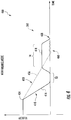
- FIG. 3 shows a velocity versus time graph 300 illustrating the deceleration paths of an elevator car 23 in motoring mode, in accordance with an embodiment of the disclosure.
- FIG. 3 displays two deceleration options including a first path 310 and a second path 350 for the controller 30 to follow in the event external power is unavailable 304 while in motoring mode.
- the controller 30 will first detect the mode of the elevator car 23, which is motoring mode for FIG. 3 .
- the controller 30 may allow the velocity of the elevator car 23 to decrease to about zero velocity.
- the controller 30 may utilize various methods including but not limited to back-emf braking and gravity to help decelerate.
- the controller 30 then allows the velocity of the elevator car 23 to increase in a direction opposite the original direction of travel to a selected creep velocity 318. For example, if an elevator car 23 was motoring up fully loaded with passengers, the controller 30 may let gravity bring the elevator car 23 to a halt (zero velocity) and then let it start to descend. The controller 30 maintains the selected creep velocity 318 for a selected duration of time T1. When the selected duration of time T1 ends, the controller 30 decreases the velocity of the elevator car 23 in the direction opposite the original direction of travel. Then at 320, the controller adjusts the velocity of the elevator car 23 as the elevator car 23 approaches the target floor and applies the brake 24 when the elevator car 23 is at the target floor.
- the controller 30 may choose a second path 350 to follow, if at point 354 the selected creep velocity is less than a selected velocity in the direction opposite the original direction of travel.
- the controller 30 deactivates the inverter at point 354 and increases the velocity of elevator car 23 in the direction opposite the original direction of travel to a selected alternate creep velocity 358.
- the controller 30 maintains the selected alternate creep velocity 358 for a selected duration of time T2 and then proceeds to decrease the velocity of the elevator car 23 in the direction opposite the original direction of travel.
- the controller adjusts the velocity of the elevator car 23 as the elevator car 23 approaches the target floor and applies the brake 24 when the elevator car 23 is at the target floor.
- FIG. 4 shows a velocity versus time graph 400 illustrating the deceleration paths of an elevator car 23 in near balance mode, in accordance with an embodiment of the disclosure.
- FIG. 4 displays two deceleration options including a first path 410 and a second path 450 for the controller 30 to follow in the event of external power is unavailable 404 while in near balance mode.
- the controller will first detect the mode of the elevator car 23, which is near balance mode for FIG. 4 .
- the controller 30 may allow the velocity of the elevator car 23 to decrease to about zero velocity at 416.
- the controller 30 may utilize various methods including but not limited to back-emf braking and gravity to help decelerate.
- the controller 30 maintains about zero velocity for a selected duration of time T3 and then the controller 30 increases the velocity of the elevator car 23 in the original direction of travel until it reaches an automatic rescue operation (ARO) velocity 418.
- the controller 30 maintains the ARO velocity for a second selected duration of time T4. Then at 420, the controller 30 decreases the velocity of the elevator car 23 as it approaches the target floor and applies the brake 24 when the elevator car 23 arrives at the target floor.
- the controller 30 may choose a second path 450 to follow in near balance mode. On the second path 450, after external power is unavailable at 404 the controller 30 determines a deceleration rate for the elevator car 23 to reach the target floor. The controller 30 then allows the velocity of the elevator car 23 to decrease in accordance with the deceleration rate determined at 456. The controller 30 may utilize various methods include including but not limited to back-emf braking and gravity to help decelerate. Then at 460, the controller 30 adjusts the velocity of the elevator car 23 as the elevator car 23 approaches the target floor and applies the brake 24 when the elevator car 23 is at the target floor.
- FIG. 5 shows a velocity versus time graph 500 illustrating the deceleration paths of an elevator car 23 in regenerative mode, in accordance with an embodiment of the disclosure.
- FIG. 5 displays three deceleration options including a first path 510, a second path 550, and a third path 580 for the controller 30 to follow in the event of external power is unavailable at 404.
- the controller 30 will first detect the mode of the elevator car 23, which is regenerative mode for FIG. 5 . In the event external power is unavailable 504, on the first path 510 the controller 30 allows the velocity of the elevator car 23 to decrease to a selected creep velocity 518, when the regenerative mode is detected.
- the controller 30 may utilize various methods including but not limited to back-emf braking and gravity to help decelerate. Then controller 30 maintains the selected creep velocity for a selected duration of time T5 and then decreases the velocity of the elevator car 23 to about zero when the selected duration of time T5 ends. Next at 520, the controller adjusts the velocity of the elevator car 23 as the elevator car 23 approaches the target floor and applies the brake 24 when the elevator car 23 is at the target floor.
- the controller 30 may choose a second path 550 to follow in regenerative mode. On the second path 550, after external power is unavailable 504 the controller 30 maintains the current velocity of the elevator car 23 for a first selected duration of time T6 at 554, when the regenerative mode is detected. The controller 30 then allows the velocity of the elevator car 23 to decrease to a selected creep velocity, when the first selected duration of time T6 ends. The controller 30 may utilize various methods including but not limited to back-emf braking and gravity to help decelerate. Next, the controller 30 maintains the selected creep velocity for a second selected duration of time T7 and then decreases the velocity of the elevator car 23 to about zero, when the second selected duration of time T7 ends. Then at 560, the controller 30 adjusts the velocity of the elevator car 23 as the elevator car 23 approaches the target floor and applies the brake 24 when the elevator car 23 is at the target floor.
- the controller 30 may choose a third path 580 to follow in regenerative mode. On the third path 580, after external power is unavailable 504, the controller 30 determines a deceleration rate for the elevator car 23 to reach the target floor. Next, the controller 30 allows the velocity of the elevator car 23 to decrease in accordance with the deceleration rate determined at 584. The controller 30 may utilize various methods including but not limited to back-emf braking and gravity to help decelerate. Then at 590, the controller 30 adjusts the velocity of the elevator car 23 as the elevator car 23 approaches the target floor and applies the brake 24 when the elevator car 23 is at the target floor.
Landscapes
- Engineering & Computer Science (AREA)
- Automation & Control Theory (AREA)
- Computer Networks & Wireless Communication (AREA)
- Elevator Control (AREA)
Claims (11)
- Procédé de fonctionnement d'un système d'ascenseur (10), le procédé comprenant :la détection, à l'aide d'un dispositif de commande (30), lorsqu'une source d'alimentation externe est indisponible ;lorsque la source d'alimentation externe est indisponible, le procédé comprenant :la commande, à l'aide du dispositif de commande (30), d'une pluralité de composants du système d'ascenseur (10), dans lequel la commande comprend le fonctionnement d'au moins l'un d'une cabine d'ascenseur (23), d'une unité d'entraînement (2Q), d'un inverseur et d'un frein (24) ;la détection, à l'aide du dispositif de commande (30), d'une direction de déplacement initiale de la cabine d'ascenseur (23) ;la détection, à l'aide du dispositif de commande (30), d'un mode de la cabine d'ascenseur (23), dans lequel le mode comprend au moins l'un d'un mode d'entraînement, d'un mode de quasi-équilibre et d'un mode de régénération ;la détermination, à l'aide du dispositif de commande (30), d'un étage cible ;le réglage, à l'aide du dispositif de commande (30), d'une vitesse de la cabine d'ascenseur (23) pour atteindre l'étage cible en réponse au mode détecté ;le fait de permettre, à l'aide du dispositif de commande (30), que la vitesse de la cabine d'ascenseur (23) diminue jusqu'à une vitesse d'environ zéro, lorsque le mode d'entraînement est détecté ; etle fait de permettre, à l'aide du dispositif de commande (30), que la vitesse de la cabine d'ascenseur (23) augmente dans une direction opposée à la direction initiale du déplacement jusqu'à une vitesse de fluage sélectionnée,caractérisé parla désactivation, à l'aide du dispositif de commande (30), de l'inverseur lorsque la vitesse de fluage sélectionnée est inférieure à une vitesse sélectionnée dans la direction opposée à la direction de déplacement initiale ;l'augmentation, à l'aide du dispositif de commande (30), de la vitesse de la cabine d'ascenseur (23) dans la direction opposée à la direction de déplacement initiale jusqu'à une vitesse de fluage alternative sélectionnée ;le maintien, à l'aide du dispositif de commande (30), de la vitesse de fluage alternative sélectionnée pendant une durée sélectionnée ;la diminution, à l'aide du dispositif de commande (30), de la vitesse de la cabine d'ascenseur (23) dans la direction opposée à la direction de déplacement initiale, lorsque la durée sélectionnée prend fin ;le réglage, à l'aide du dispositif de commande (30), de la vitesse de la cabine d'ascenseur (23) lorsque la cabine d'ascenseur (23) se rapproche de l'étage cible ; etl'application, à l'aide du dispositif de commande (30), du frein (24) lorsque la cabine d'ascenseur (23) est à l'étage cible.
- Procédé selon la revendication 1, comprenant en outre :le maintien, à l'aide du dispositif de commande (30), de la vitesse de fluage sélectionnée pendant une durée sélectionnée ;la diminution, à l'aide du dispositif de commande (30), de la vitesse de la cabine d'ascenseur (23) dans la direction opposée à la direction de déplacement initiale, lorsque la durée sélectionnée prend fin ;
le réglage, à l'aide du dispositif de commande (30), de la vitesse de la cabine d'ascenseur (23) lorsque la cabine d'ascenseur (23) se rapproche de l'étage cible ; et l'application, à l'aide du dispositif de commande (30), du frein (24) lorsque la cabine d'ascenseur (23) est à l'étage cible. - Procédé selon l'une quelconque des revendications 1 à 2, comprenant en outre :la détermination, à l'aide du dispositif de commande (30), d'un taux de décélération permettant à la cabine d'ascenseur (23) d'atteindre l'étage cible, lorsque le mode de quasi-équilibre est détecté ;le fait de permettre, à l'aide du dispositif de commande (30), que la vitesse de la cabine d'ascenseur (23) diminue en fonction du taux de décélération déterminé ;le réglage, à l'aide du dispositif de commande (30), de la vitesse de la cabine d'ascenseur (23) lorsque la cabine d'ascenseur (23) se rapproche de l'étage cible ; etl'application, à l'aide du dispositif de commande (30), du frein (24) lorsque la cabine d'ascenseur (23) est à l'étage cible.
- Procédé selon l'une quelconque des revendications 1 à 3, comprenant en outre :le fait de permettre, à l'aide du dispositif de commande (30), que la vitesse de la cabine d'ascenseur (23) soit réduite à une vitesse de fluage sélectionnée, lorsque le mode de régénération est détecté ;le maintien, à l'aide du dispositif de commande (30), de la vitesse de fluage sélectionnée pendant une durée sélectionnée ;la diminution, à l'aide du dispositif de commande (30), de la vitesse de la cabine d'ascenseur (23) jusqu'à environ zéro, lorsque la durée sélectionnée prend fin ;le réglage, à l'aide du dispositif de commande (30), de la vitesse de la cabine d'ascenseur (23) lorsque la cabine d'ascenseur se rapproche de l'étage cible ; etl'application, à l'aide du dispositif de commande (30), du frein (24) lorsque la cabine d'ascenseur (23) est à l'étage cible.
- Procédé selon l'une quelconque des revendications 1 à 4, comprenant en outre :le maintien, à l'aide du dispositif de commande (30), de la vitesse actuelle de la cabine d'ascenseur (23) pendant une première durée sélectionnée, lorsque le mode de régénération est détecté ;le fait de permettre, à l'aide du dispositif de commande (30), que la vitesse de la cabine d'ascenseur (23) soit réduite à une vitesse de fluage sélectionnée, lorsque la première durée sélectionnée prend fin ;le maintien, à l'aide du dispositif de commande (30), de la vitesse de fluage sélectionnée pendant une seconde durée sélectionnée ;la diminution, à l'aide du dispositif de commande (30), de la vitesse de la cabine d'ascenseur (23) jusqu'à environ zéro, lorsque la seconde durée sélectionnée prend fin ;le réglage, à l'aide du dispositif de commande (30), de la vitesse de la cabine d'ascenseur (23) lorsque la cabine d'ascenseur se rapproche de l'étage cible ; etl'application, à l'aide du dispositif de commande (30), du frein (24) lorsque la cabine d'ascenseur (23) est à l'étage cible.
- Procédé selon l'une quelconque des revendications 1 à 5, comprenant en outre :la détermination, à l'aide du dispositif de commande (30), d'un taux de décélération permettant à la cabine d'ascenseur (23) d'atteindre l'étage cible, lorsque le mode de régénération est détecté ;le fait de permettre, à l'aide du dispositif de commande (30), que la vitesse de la cabine d'ascenseur (23) diminue en fonction du taux de décélération déterminé ;le réglage, à l'aide du dispositif de commande (30), de la vitesse de la cabine d'ascenseur (23) lorsque la cabine d'ascenseur se rapproche de l'étage cible ; etl'application, à l'aide du dispositif de commande (30), du frein (24) lorsque la cabine d'ascenseur (23) est à l'étage cible.
- Appareil pour faire fonctionner un système d'ascenseur (10), l'appareil comprenant :une cabine d'ascenseur (23) ;une unité d'entraînement (20) ;un inverseur ;un frein (24) ;un dispositif de commande (30) pour commander une pluralité de composants du système d'ascenseur (10), dans lequel le dispositif de commande comprend le fonctionnement d'au moins l'un de la cabine d'ascenseur (23), de l'unité d'entraînement (20), de l'inverseur et du frein (24),dans lequel le dispositif de commande (30) est configuré pour effectuer des opérations comprenant :le fait de détecter quand la source d'alimentation externe est indisponible,la détection d'une direction de déplacement initiale de la cabine d'ascenseur (23),la détection d'un mode de la cabine d'ascenseur (23), dans lequel le mode comprend au moins l'un d'un mode d'entraînement, d'un mode de quasi-équilibre et d'un mode de régénération,la détermination d'un étage cible, etle réglage d'une vitesse de la cabine d'ascenseur (23) pour atteindre l'étage cible en réponse au mode détecté,caractérisé en ce que les opérations comprennent en outre :le fait de permettre à la vitesse de la cabine d'ascenseur de diminuer jusqu'à une vitesse d'environ zéro lorsque le mode d'entraînement est détecté,le fait de permettre à la vitesse de la cabine d'ascenseur (23) d'augmenter dans une direction opposée à la direction de déplacement initiale jusqu'à une vitesse de fluage sélectionnée,la désactivation de l'inverseur lorsque la vitesse de fluage sélectionnée est inférieure à une vitesse sélectionnée dans la direction opposée à la direction de déplacement initiale ;l'augmentation de la vitesse de la cabine d'ascenseur (23) dans la direction opposée à la direction de déplacement initiale jusqu'à une vitesse de fluage sélectionnée ;le maintien de la vitesse de fluage alternative sélectionnée pendant une durée sélectionnée ;la diminution de la vitesse de la cabine d'ascenseur (23) dans la direction opposée à la direction de déplacement initiale, lorsque la durée sélectionnée prend fin ;le réglage de la vitesse de la cabine d'ascenseur (23) lorsque la cabine d'ascenseur (23) se rapproche de l'étage cible ; etl'application du frein lorsque la cabine d'ascenseur (23) est à l'étage cible.
- Appareil selon la revendication 7, dans lequel les opérations comprennent en outre :le maintien de la vitesse de fluage sélectionnée pendant une durée sélectionnée ;la diminution de la vitesse de la cabine d'ascenseur (23) dans la direction opposée à la direction de déplacement initiale, lorsque la durée sélectionnée prend fin ;le réglage de la vitesse de la cabine d'ascenseur (23) lorsque la cabine d'ascenseur se rapproche de l'étage cible ; etl'application du frein (24) lorsque la cabine d'ascenseur (23) est à l'étage cible.
- Appareil selon la revendication 7 ou 8, dans lequel les opérations comprennent en outre :la détermination d'un taux de décélération pour que la cabine d'ascenseur (23) atteigne l'étage cible, lorsque le mode de quasi-équilibre est détecté ;le fait de permettre à la vitesse de la cabine d'ascenseur (23) de diminuer en fonction du taux de décélération déterminé ;le réglage de la vitesse de la cabine d'ascenseur (23) lorsque la cabine d'ascenseur se rapproche de l'étage cible ; etl'application du frein (24) lorsque la cabine d'ascenseur (23) est à l'étage cible.
- Appareil selon l'une quelconque des revendications 7 à 9, dans lequel les opérations comprennent en outre :le fait de permettre à la vitesse de la cabine d'ascenseur (23) de diminuer jusqu'à une vitesse de fluage sélectionnée, lorsque le mode de régénération est détecté ;le maintien de la vitesse de fluage sélectionnée pendant une durée sélectionnée ;la diminution de la vitesse de la cabine d'ascenseur (23) jusqu'à environ zéro, lorsque la durée sélectionnée prend fin ;le réglage de la vitesse de la cabine d'ascenseur (23) lorsque la cabine d'ascenseur (23) se rapproche de l'étage cible ; etl'application du frein (24) lorsque la cabine d'ascenseur (23) est à l'étage cible.
- Appareil selon l'une quelconque des revendications 7 à 10, dans lequel les opérations comprennent en outre :A : le maintien de la vitesse actuelle de la cabine d'ascenseur (23) pendant une première durée sélectionnée, lorsque le mode de régénération est détecté ;
le fait de permettre à la vitesse de la cabine d'ascenseur (23) de diminuer jusqu'à une vitesse de fluage sélectionnée, lorsque la première durée sélectionnée prend fin ;
le maintien de la vitesse de fluage sélectionnée pendant une seconde durée sélectionnée ;
la diminution de la vitesse de la cabine d'ascenseur (23) jusqu'à environ zéro, lorsque la seconde durée sélectionnée prend fin ;
le réglage de la vitesse de la cabine d'ascenseur (23) lorsque la cabine d'ascenseur se rapproche de l'étage cible ; et
l'application du frein (24) lorsque la cabine d'ascenseur (23) est à l'étage cible ; et/ouB : la détermination d'un taux de décélération pour que la cabine d'ascenseur atteigne l'étage cible, lorsque le mode de régénération est détecté ;
le fait de permettre à la vitesse de la cabine d'ascenseur (23) de diminuer en fonction du taux de décélération déterminé ;
le réglage de la vitesse de la cabine d'ascenseur (23) lorsque la cabine d'ascenseur (23) se rapproche de l'étage cible ; et
l'application du frein (24) lorsque la cabine d'ascenseur (23) est à l'étage cible.
Applications Claiming Priority (1)
| Application Number | Priority Date | Filing Date | Title |
|---|---|---|---|
| US15/056,158 US9809418B2 (en) | 2016-02-29 | 2016-02-29 | Advanced smooth rescue operation |
Publications (2)
| Publication Number | Publication Date |
|---|---|
| EP3210923A1 EP3210923A1 (fr) | 2017-08-30 |
| EP3210923B1 true EP3210923B1 (fr) | 2019-08-21 |
Family
ID=58158969
Family Applications (1)
| Application Number | Title | Priority Date | Filing Date |
|---|---|---|---|
| EP17157794.3A Active EP3210923B1 (fr) | 2016-02-29 | 2017-02-24 | Opération avancée de sauvetage en douceur |
Country Status (6)
| Country | Link |
|---|---|
| US (2) | US9809418B2 (fr) |
| EP (1) | EP3210923B1 (fr) |
| JP (1) | JP6978839B2 (fr) |
| KR (1) | KR102679056B1 (fr) |
| CN (1) | CN107128756B (fr) |
| ES (1) | ES2749172T3 (fr) |
Families Citing this family (4)
| Publication number | Priority date | Publication date | Assignee | Title |
|---|---|---|---|---|
| EP3253703B1 (fr) * | 2015-02-05 | 2019-04-10 | Otis Elevator Company | Système de contrôle pour un ascenseur sans câble |
| US20180296313A1 (en) * | 2015-09-23 | 2018-10-18 | Novus Scientific Ab | Three-dimensional medical implant for regeneration of soft tissue |
| CN108657893B (zh) * | 2018-05-28 | 2020-07-28 | 苏州汇川技术有限公司 | 一种电梯救援方法、系统以及控制器 |
| CN115258855B (zh) * | 2021-04-30 | 2023-12-26 | 迅达(中国)电梯有限公司 | 校准位置参数的方法及装置 |
Family Cites Families (35)
| Publication number | Priority date | Publication date | Assignee | Title |
|---|---|---|---|---|
| JPS5889572A (ja) | 1981-11-16 | 1983-05-27 | 三菱電機株式会社 | 交流エレベ−タの運転装置 |
| JPH0697875B2 (ja) | 1987-05-20 | 1994-11-30 | 日本オ−チス・エレベ−タ株式会社 | エレベ−タ駆動用インバ−タ |
| JPH0780653B2 (ja) | 1989-05-29 | 1995-08-30 | 三菱電機株式会社 | エレベータ制御装置 |
| US5035301A (en) | 1989-07-03 | 1991-07-30 | Otis Elevator Company | Elevator speed dictation system |
| JP2656684B2 (ja) * | 1991-06-12 | 1997-09-24 | 三菱電機株式会社 | エレベータの停電時運転装置 |
| JP3302722B2 (ja) * | 1992-06-11 | 2002-07-15 | 三菱電機株式会社 | エレベータの制御装置 |
| KR100186370B1 (ko) * | 1996-10-24 | 1999-04-15 | 이종수 | 엘리베이터의 정전시 비상 운전 장치 |
| US5893432A (en) | 1996-12-31 | 1999-04-13 | Inventio Ag | Controlled emergency stop apparatus for elevators |
| KR100312771B1 (ko) | 1998-12-15 | 2002-05-09 | 장병우 | 엘리베이터의정전운전제어장치및방법 |
| US6196355B1 (en) * | 1999-03-26 | 2001-03-06 | Otis Elevator Company | Elevator rescue system |
| JP4249364B2 (ja) | 2000-02-28 | 2009-04-02 | 三菱電機株式会社 | エレベータの制御装置 |
| JP4154908B2 (ja) * | 2002-03-27 | 2008-09-24 | フジテック株式会社 | 交流エレベータの電源装置 |
| JP2004043078A (ja) * | 2002-07-10 | 2004-02-12 | Mitsubishi Electric Corp | エレベータの制御装置 |
| US6802395B1 (en) | 2003-03-28 | 2004-10-12 | Kone Corporation | System for control and deceleration of elevator during emergency braking |
| US7540356B2 (en) | 2005-10-18 | 2009-06-02 | Thyssen Elevator Capital Corp. | Method and apparatus to prevent or minimize the entrapment of passengers in elevators during a power failure |
| JP5190178B2 (ja) * | 2006-02-16 | 2013-04-24 | 東芝エレベータ株式会社 | エレベータ制御装置 |
| KR101014960B1 (ko) * | 2006-07-27 | 2011-02-15 | 미쓰비시덴키 가부시키가이샤 | 엘리베이터 장치 |
| US7931127B2 (en) * | 2006-08-03 | 2011-04-26 | Mitsubishi Electric Corporation | Elevator apparatus |
| FI119767B (fi) | 2006-08-14 | 2009-03-13 | Kone Corp | Hissijärjestelmä ja menetelmä turvallisuuden varmistamiseksi hissijärjestelmässä |
| US20080073157A1 (en) * | 2006-09-08 | 2008-03-27 | Ashur Kanon | Auxiliary power supply apparatus and method |
| ES2689089T3 (es) | 2007-02-13 | 2018-11-08 | Otis Elevator Company | Operación automática de rescate para un sistema de variador regenerativo |
| FI120828B (fi) | 2007-02-21 | 2010-03-31 | Kone Corp | Elektroninen liikkeenrajoitin ja menetelmä elektronisen liikkeenrajoittimen ohjaamiseksi |
| CN100560462C (zh) * | 2007-06-01 | 2009-11-18 | 苏州江南嘉捷电梯股份有限公司 | 同步电机驱动电梯的停电救援方法 |
| US8267224B2 (en) | 2007-07-17 | 2012-09-18 | Inventio Ag | Special operating mode for stopping an elevator car |
| FI120070B (fi) * | 2007-10-01 | 2009-06-15 | Kone Corp | Sähkökäytön annon rajoittaminen sekä hissin suojaus |
| EP2318300B1 (fr) * | 2008-07-25 | 2013-05-22 | Otis Elevator Company | Procédé permettant d'actionner un ascenseur en mode d'urgence |
| JP2011063428A (ja) * | 2009-09-18 | 2011-03-31 | Toshiba Elevator Co Ltd | エレベータの救出運転システム |
| DE102009049267A1 (de) | 2009-10-13 | 2011-04-21 | K-Solutions Gmbh | Verfahren zur Steuerung eines Aufzugs und einer Aufzugsgruppe |
| EP2332872A1 (fr) | 2009-12-11 | 2011-06-15 | Inventio AG | Frein d'ascenseur sélectif durant un arrêt d'urgence |
| CN201821147U (zh) * | 2010-08-24 | 2011-05-04 | 东莞市三洋电梯有限公司 | 一种电梯能源再生自用装置 |
| US10087044B2 (en) | 2013-01-17 | 2018-10-02 | Otis Elevator Company | Enhanced deceleration propulsion system for elevators |
| JP5865945B2 (ja) | 2014-04-28 | 2016-02-17 | 東芝エレベータ株式会社 | エレベータ制御装置 |
| JP6237474B2 (ja) * | 2014-05-30 | 2017-11-29 | 株式会社明電舎 | エレベータのかご移動制御装置およびかご移動制御方法 |
| CN104150314A (zh) * | 2014-08-05 | 2014-11-19 | 曾海平 | 一种电梯紧急救援装置 |
| CN104176569B (zh) * | 2014-09-09 | 2016-03-23 | 西继迅达(许昌)电梯有限公司 | 一种电梯停电平层救援装置和方法 |
-
2016
- 2016-02-29 US US15/056,158 patent/US9809418B2/en active Active
-
2017
- 2017-02-24 ES ES17157794T patent/ES2749172T3/es active Active
- 2017-02-24 EP EP17157794.3A patent/EP3210923B1/fr active Active
- 2017-02-27 KR KR1020170025524A patent/KR102679056B1/ko active Active
- 2017-02-27 JP JP2017034245A patent/JP6978839B2/ja active Active
- 2017-02-27 CN CN201710111202.7A patent/CN107128756B/zh active Active
- 2017-09-28 US US15/718,822 patent/US20180016114A1/en not_active Abandoned
Non-Patent Citations (1)
| Title |
|---|
| None * |
Also Published As
| Publication number | Publication date |
|---|---|
| JP2017154893A (ja) | 2017-09-07 |
| JP6978839B2 (ja) | 2021-12-08 |
| US20170247222A1 (en) | 2017-08-31 |
| US9809418B2 (en) | 2017-11-07 |
| CN107128756A (zh) | 2017-09-05 |
| EP3210923A1 (fr) | 2017-08-30 |
| KR20170101817A (ko) | 2017-09-06 |
| US20180016114A1 (en) | 2018-01-18 |
| KR102679056B1 (ko) | 2024-07-01 |
| CN107128756B (zh) | 2021-01-26 |
| ES2749172T3 (es) | 2020-03-19 |
Similar Documents
| Publication | Publication Date | Title |
|---|---|---|
| EP3228572B1 (fr) | Opération de sauvetage ininterrompue | |
| EP2318300B1 (fr) | Procédé permettant d'actionner un ascenseur en mode d'urgence | |
| CN102459050B (zh) | 执行升降机救援运行的升降机系统和方法 | |
| US10822197B2 (en) | Elevator run profile modification for smooth rescue | |
| US20180016114A1 (en) | Advanced smooth rescue operation | |
| JP6089796B2 (ja) | エレベータの停電時救出運転装置 | |
| JP2009035408A (ja) | エレベータ | |
| JP2013147328A (ja) | 非常用電源で運転されるエレベータ | |
| EP3103751A1 (fr) | Arrêt d'urgence assistée d'entraînement | |
| US20180215582A1 (en) | Uninterrupted rescue operation | |
| JP2005247512A (ja) | エレベータの故障時救出運転装置 | |
| EP3597582A1 (fr) | Opération de sauvetage ininterrompue | |
| JP2009298582A (ja) | エレベータの制御装置 | |
| BR102017003803B1 (pt) | Método e aparelho para operar um sistema de elevador | |
| KR101734487B1 (ko) | 엘리베이터 시스템 | |
| BR102017003803A2 (pt) | Method and apparatus for operating a lifter system | |
| HK1170716B (en) | Elevator system and method of performing an elevator rescue run |
Legal Events
| Date | Code | Title | Description |
|---|---|---|---|
| PUAI | Public reference made under article 153(3) epc to a published international application that has entered the european phase |
Free format text: ORIGINAL CODE: 0009012 |
|
| STAA | Information on the status of an ep patent application or granted ep patent |
Free format text: STATUS: THE APPLICATION HAS BEEN PUBLISHED |
|
| AK | Designated contracting states |
Kind code of ref document: A1 Designated state(s): AL AT BE BG CH CY CZ DE DK EE ES FI FR GB GR HR HU IE IS IT LI LT LU LV MC MK MT NL NO PL PT RO RS SE SI SK SM TR |
|
| AX | Request for extension of the european patent |
Extension state: BA ME |
|
| RAP1 | Party data changed (applicant data changed or rights of an application transferred) |
Owner name: OTIS ELEVATOR COMPANY |
|
| STAA | Information on the status of an ep patent application or granted ep patent |
Free format text: STATUS: REQUEST FOR EXAMINATION WAS MADE |
|
| 17P | Request for examination filed |
Effective date: 20180227 |
|
| RBV | Designated contracting states (corrected) |
Designated state(s): AL AT BE BG CH CY CZ DE DK EE ES FI FR GB GR HR HU IE IS IT LI LT LU LV MC MK MT NL NO PL PT RO RS SE SI SK SM TR |
|
| GRAP | Despatch of communication of intention to grant a patent |
Free format text: ORIGINAL CODE: EPIDOSNIGR1 |
|
| STAA | Information on the status of an ep patent application or granted ep patent |
Free format text: STATUS: GRANT OF PATENT IS INTENDED |
|
| INTG | Intention to grant announced |
Effective date: 20190405 |
|
| GRAS | Grant fee paid |
Free format text: ORIGINAL CODE: EPIDOSNIGR3 |
|
| GRAA | (expected) grant |
Free format text: ORIGINAL CODE: 0009210 |
|
| STAA | Information on the status of an ep patent application or granted ep patent |
Free format text: STATUS: THE PATENT HAS BEEN GRANTED |
|
| AK | Designated contracting states |
Kind code of ref document: B1 Designated state(s): AL AT BE BG CH CY CZ DE DK EE ES FI FR GB GR HR HU IE IS IT LI LT LU LV MC MK MT NL NO PL PT RO RS SE SI SK SM TR |
|
| REG | Reference to a national code |
Ref country code: GB Ref legal event code: FG4D |
|
| REG | Reference to a national code |
Ref country code: CH Ref legal event code: EP |
|
| REG | Reference to a national code |
Ref country code: DE Ref legal event code: R096 Ref document number: 602017006230 Country of ref document: DE |
|
| REG | Reference to a national code |
Ref country code: AT Ref legal event code: REF Ref document number: 1169520 Country of ref document: AT Kind code of ref document: T Effective date: 20190915 |
|
| REG | Reference to a national code |
Ref country code: IE Ref legal event code: FG4D |
|
| REG | Reference to a national code |
Ref country code: LT Ref legal event code: MG4D |
|
| REG | Reference to a national code |
Ref country code: NL Ref legal event code: MP Effective date: 20190821 |
|
| PG25 | Lapsed in a contracting state [announced via postgrant information from national office to epo] |
Ref country code: NL Free format text: LAPSE BECAUSE OF FAILURE TO SUBMIT A TRANSLATION OF THE DESCRIPTION OR TO PAY THE FEE WITHIN THE PRESCRIBED TIME-LIMIT Effective date: 20190821 Ref country code: BG Free format text: LAPSE BECAUSE OF FAILURE TO SUBMIT A TRANSLATION OF THE DESCRIPTION OR TO PAY THE FEE WITHIN THE PRESCRIBED TIME-LIMIT Effective date: 20191121 Ref country code: SE Free format text: LAPSE BECAUSE OF FAILURE TO SUBMIT A TRANSLATION OF THE DESCRIPTION OR TO PAY THE FEE WITHIN THE PRESCRIBED TIME-LIMIT Effective date: 20190821 Ref country code: NO Free format text: LAPSE BECAUSE OF FAILURE TO SUBMIT A TRANSLATION OF THE DESCRIPTION OR TO PAY THE FEE WITHIN THE PRESCRIBED TIME-LIMIT Effective date: 20191121 Ref country code: HR Free format text: LAPSE BECAUSE OF FAILURE TO SUBMIT A TRANSLATION OF THE DESCRIPTION OR TO PAY THE FEE WITHIN THE PRESCRIBED TIME-LIMIT Effective date: 20190821 Ref country code: FI Free format text: LAPSE BECAUSE OF FAILURE TO SUBMIT A TRANSLATION OF THE DESCRIPTION OR TO PAY THE FEE WITHIN THE PRESCRIBED TIME-LIMIT Effective date: 20190821 Ref country code: PT Free format text: LAPSE BECAUSE OF FAILURE TO SUBMIT A TRANSLATION OF THE DESCRIPTION OR TO PAY THE FEE WITHIN THE PRESCRIBED TIME-LIMIT Effective date: 20191223 Ref country code: LT Free format text: LAPSE BECAUSE OF FAILURE TO SUBMIT A TRANSLATION OF THE DESCRIPTION OR TO PAY THE FEE WITHIN THE PRESCRIBED TIME-LIMIT Effective date: 20190821 |
|
| PG25 | Lapsed in a contracting state [announced via postgrant information from national office to epo] |
Ref country code: LV Free format text: LAPSE BECAUSE OF FAILURE TO SUBMIT A TRANSLATION OF THE DESCRIPTION OR TO PAY THE FEE WITHIN THE PRESCRIBED TIME-LIMIT Effective date: 20190821 Ref country code: IS Free format text: LAPSE BECAUSE OF FAILURE TO SUBMIT A TRANSLATION OF THE DESCRIPTION OR TO PAY THE FEE WITHIN THE PRESCRIBED TIME-LIMIT Effective date: 20191221 Ref country code: RS Free format text: LAPSE BECAUSE OF FAILURE TO SUBMIT A TRANSLATION OF THE DESCRIPTION OR TO PAY THE FEE WITHIN THE PRESCRIBED TIME-LIMIT Effective date: 20190821 Ref country code: GR Free format text: LAPSE BECAUSE OF FAILURE TO SUBMIT A TRANSLATION OF THE DESCRIPTION OR TO PAY THE FEE WITHIN THE PRESCRIBED TIME-LIMIT Effective date: 20191122 Ref country code: AL Free format text: LAPSE BECAUSE OF FAILURE TO SUBMIT A TRANSLATION OF THE DESCRIPTION OR TO PAY THE FEE WITHIN THE PRESCRIBED TIME-LIMIT Effective date: 20190821 |
|
| REG | Reference to a national code |
Ref country code: AT Ref legal event code: MK05 Ref document number: 1169520 Country of ref document: AT Kind code of ref document: T Effective date: 20190821 |
|
| REG | Reference to a national code |
Ref country code: ES Ref legal event code: FG2A Ref document number: 2749172 Country of ref document: ES Kind code of ref document: T3 Effective date: 20200319 |
|
| PG25 | Lapsed in a contracting state [announced via postgrant information from national office to epo] |
Ref country code: TR Free format text: LAPSE BECAUSE OF FAILURE TO SUBMIT A TRANSLATION OF THE DESCRIPTION OR TO PAY THE FEE WITHIN THE PRESCRIBED TIME-LIMIT Effective date: 20190821 |
|
| PG25 | Lapsed in a contracting state [announced via postgrant information from national office to epo] |
Ref country code: PL Free format text: LAPSE BECAUSE OF FAILURE TO SUBMIT A TRANSLATION OF THE DESCRIPTION OR TO PAY THE FEE WITHIN THE PRESCRIBED TIME-LIMIT Effective date: 20190821 Ref country code: RO Free format text: LAPSE BECAUSE OF FAILURE TO SUBMIT A TRANSLATION OF THE DESCRIPTION OR TO PAY THE FEE WITHIN THE PRESCRIBED TIME-LIMIT Effective date: 20190821 Ref country code: EE Free format text: LAPSE BECAUSE OF FAILURE TO SUBMIT A TRANSLATION OF THE DESCRIPTION OR TO PAY THE FEE WITHIN THE PRESCRIBED TIME-LIMIT Effective date: 20190821 Ref country code: DK Free format text: LAPSE BECAUSE OF FAILURE TO SUBMIT A TRANSLATION OF THE DESCRIPTION OR TO PAY THE FEE WITHIN THE PRESCRIBED TIME-LIMIT Effective date: 20190821 Ref country code: AT Free format text: LAPSE BECAUSE OF FAILURE TO SUBMIT A TRANSLATION OF THE DESCRIPTION OR TO PAY THE FEE WITHIN THE PRESCRIBED TIME-LIMIT Effective date: 20190821 Ref country code: IT Free format text: LAPSE BECAUSE OF FAILURE TO SUBMIT A TRANSLATION OF THE DESCRIPTION OR TO PAY THE FEE WITHIN THE PRESCRIBED TIME-LIMIT Effective date: 20190821 |
|
| PG25 | Lapsed in a contracting state [announced via postgrant information from national office to epo] |
Ref country code: SM Free format text: LAPSE BECAUSE OF FAILURE TO SUBMIT A TRANSLATION OF THE DESCRIPTION OR TO PAY THE FEE WITHIN THE PRESCRIBED TIME-LIMIT Effective date: 20190821 Ref country code: CZ Free format text: LAPSE BECAUSE OF FAILURE TO SUBMIT A TRANSLATION OF THE DESCRIPTION OR TO PAY THE FEE WITHIN THE PRESCRIBED TIME-LIMIT Effective date: 20190821 Ref country code: SK Free format text: LAPSE BECAUSE OF FAILURE TO SUBMIT A TRANSLATION OF THE DESCRIPTION OR TO PAY THE FEE WITHIN THE PRESCRIBED TIME-LIMIT Effective date: 20190821 Ref country code: IS Free format text: LAPSE BECAUSE OF FAILURE TO SUBMIT A TRANSLATION OF THE DESCRIPTION OR TO PAY THE FEE WITHIN THE PRESCRIBED TIME-LIMIT Effective date: 20200224 |
|
| REG | Reference to a national code |
Ref country code: DE Ref legal event code: R097 Ref document number: 602017006230 Country of ref document: DE |
|
| PLBE | No opposition filed within time limit |
Free format text: ORIGINAL CODE: 0009261 |
|
| STAA | Information on the status of an ep patent application or granted ep patent |
Free format text: STATUS: NO OPPOSITION FILED WITHIN TIME LIMIT |
|
| PG2D | Information on lapse in contracting state deleted |
Ref country code: IS |
|
| 26N | No opposition filed |
Effective date: 20200603 |
|
| PG25 | Lapsed in a contracting state [announced via postgrant information from national office to epo] |
Ref country code: SI Free format text: LAPSE BECAUSE OF FAILURE TO SUBMIT A TRANSLATION OF THE DESCRIPTION OR TO PAY THE FEE WITHIN THE PRESCRIBED TIME-LIMIT Effective date: 20190821 |
|
| REG | Reference to a national code |
Ref country code: CH Ref legal event code: PL |
|
| REG | Reference to a national code |
Ref country code: BE Ref legal event code: MM Effective date: 20200229 |
|
| PG25 | Lapsed in a contracting state [announced via postgrant information from national office to epo] |
Ref country code: LU Free format text: LAPSE BECAUSE OF NON-PAYMENT OF DUE FEES Effective date: 20200224 Ref country code: MC Free format text: LAPSE BECAUSE OF FAILURE TO SUBMIT A TRANSLATION OF THE DESCRIPTION OR TO PAY THE FEE WITHIN THE PRESCRIBED TIME-LIMIT Effective date: 20190821 |
|
| PG25 | Lapsed in a contracting state [announced via postgrant information from national office to epo] |
Ref country code: LI Free format text: LAPSE BECAUSE OF NON-PAYMENT OF DUE FEES Effective date: 20200229 Ref country code: CH Free format text: LAPSE BECAUSE OF NON-PAYMENT OF DUE FEES Effective date: 20200229 |
|
| PG25 | Lapsed in a contracting state [announced via postgrant information from national office to epo] |
Ref country code: IE Free format text: LAPSE BECAUSE OF NON-PAYMENT OF DUE FEES Effective date: 20200224 |
|
| PG25 | Lapsed in a contracting state [announced via postgrant information from national office to epo] |
Ref country code: BE Free format text: LAPSE BECAUSE OF NON-PAYMENT OF DUE FEES Effective date: 20200229 |
|
| PG25 | Lapsed in a contracting state [announced via postgrant information from national office to epo] |
Ref country code: MT Free format text: LAPSE BECAUSE OF FAILURE TO SUBMIT A TRANSLATION OF THE DESCRIPTION OR TO PAY THE FEE WITHIN THE PRESCRIBED TIME-LIMIT Effective date: 20190821 Ref country code: CY Free format text: LAPSE BECAUSE OF FAILURE TO SUBMIT A TRANSLATION OF THE DESCRIPTION OR TO PAY THE FEE WITHIN THE PRESCRIBED TIME-LIMIT Effective date: 20190821 |
|
| PG25 | Lapsed in a contracting state [announced via postgrant information from national office to epo] |
Ref country code: MK Free format text: LAPSE BECAUSE OF FAILURE TO SUBMIT A TRANSLATION OF THE DESCRIPTION OR TO PAY THE FEE WITHIN THE PRESCRIBED TIME-LIMIT Effective date: 20190821 |
|
| PGFP | Annual fee paid to national office [announced via postgrant information from national office to epo] |
Ref country code: GB Payment date: 20260121 Year of fee payment: 10 |
|
| PGFP | Annual fee paid to national office [announced via postgrant information from national office to epo] |
Ref country code: ES Payment date: 20260302 Year of fee payment: 10 |
|
| PGFP | Annual fee paid to national office [announced via postgrant information from national office to epo] |
Ref country code: DE Payment date: 20260121 Year of fee payment: 10 |
|
| PGFP | Annual fee paid to national office [announced via postgrant information from national office to epo] |
Ref country code: FR Payment date: 20260121 Year of fee payment: 10 |