EP3211136A1 - Appareil de criblage de déchets - Google Patents
Appareil de criblage de déchets Download PDFInfo
- Publication number
- EP3211136A1 EP3211136A1 EP17153903.4A EP17153903A EP3211136A1 EP 3211136 A1 EP3211136 A1 EP 3211136A1 EP 17153903 A EP17153903 A EP 17153903A EP 3211136 A1 EP3211136 A1 EP 3211136A1
- Authority
- EP
- European Patent Office
- Prior art keywords
- waste
- screener
- main body
- water
- disposed
- Prior art date
- Legal status (The legal status is an assumption and is not a legal conclusion. Google has not performed a legal analysis and makes no representation as to the accuracy of the status listed.)
- Granted
Links
Images





Classifications
-
- B—PERFORMING OPERATIONS; TRANSPORTING
- B01—PHYSICAL OR CHEMICAL PROCESSES OR APPARATUS IN GENERAL
- B01D—SEPARATION
- B01D33/00—Filters with filtering elements which move during the filtering operation
- B01D33/056—Construction of filtering bands or supporting belts, e.g. devices for centering, mounting or sealing the filtering bands or the supporting belts
-
- B—PERFORMING OPERATIONS; TRANSPORTING
- B01—PHYSICAL OR CHEMICAL PROCESSES OR APPARATUS IN GENERAL
- B01D—SEPARATION
- B01D33/00—Filters with filtering elements which move during the filtering operation
- B01D33/70—Filters with filtering elements which move during the filtering operation having feed or discharge devices
- B01D33/76—Filters with filtering elements which move during the filtering operation having feed or discharge devices for discharging the filter cake, e.g. chutes
-
- E—FIXED CONSTRUCTIONS
- E02—HYDRAULIC ENGINEERING; FOUNDATIONS; SOIL SHIFTING
- E02B—HYDRAULIC ENGINEERING
- E02B8/00—Details of barrages or weirs ; Energy dissipating devices carried by lock or dry-dock gates
- E02B8/02—Sediment base gates; Sand sluices; Structures for retaining arresting waterborne material
- E02B8/023—Arresting devices for waterborne materials
- E02B8/026—Cleaning devices
-
- B—PERFORMING OPERATIONS; TRANSPORTING
- B01—PHYSICAL OR CHEMICAL PROCESSES OR APPARATUS IN GENERAL
- B01D—SEPARATION
- B01D33/00—Filters with filtering elements which move during the filtering operation
- B01D33/04—Filters with filtering elements which move during the filtering operation with filtering bands or the like supported on cylinders which are impervious for filtering
-
- B—PERFORMING OPERATIONS; TRANSPORTING
- B01—PHYSICAL OR CHEMICAL PROCESSES OR APPARATUS IN GENERAL
- B01D—SEPARATION
- B01D33/00—Filters with filtering elements which move during the filtering operation
- B01D33/333—Filters with filtering elements which move during the filtering operation with individual filtering elements moving along a closed path
-
- B—PERFORMING OPERATIONS; TRANSPORTING
- B01—PHYSICAL OR CHEMICAL PROCESSES OR APPARATUS IN GENERAL
- B01D—SEPARATION
- B01D33/00—Filters with filtering elements which move during the filtering operation
- B01D33/44—Regenerating the filter material in the filter
- B01D33/46—Regenerating the filter material in the filter by scrapers, brushes nozzles or the like acting on the cake-side of the filtering element
- B01D33/461—Regenerating the filter material in the filter by scrapers, brushes nozzles or the like acting on the cake-side of the filtering element brushes
-
- B—PERFORMING OPERATIONS; TRANSPORTING
- B01—PHYSICAL OR CHEMICAL PROCESSES OR APPARATUS IN GENERAL
- B01D—SEPARATION
- B01D33/00—Filters with filtering elements which move during the filtering operation
- B01D33/80—Accessories
- B01D33/801—Driving means, shaft packing systems or the like
-
- C—CHEMISTRY; METALLURGY
- C02—TREATMENT OF WATER, WASTE WATER, SEWAGE, OR SLUDGE
- C02F—TREATMENT OF WATER, WASTE WATER, SEWAGE, OR SLUDGE
- C02F1/00—Treatment of water, waste water, or sewage
- C02F1/001—Processes for the treatment of water whereby the filtration technique is of importance
Definitions
- the present disclosure relates to a waste screening apparatus, and, more particularly, to a waste screening apparatus with three-directional waste-water filtrations.
- the wastes may block a water flow channel or cause components in a waste water treatment plant not to work.
- a grid type screen has been installed in the water flow channel to filter the waste from the water to allow only the passage of the waste-removed water.
- the waste removed by the screen When the waste removed by the screen is not separated from the screen rapidly, the waste may be deposited on the screen to block the holes in the screen. Otherwise, the holes may allow only the passage of the waste-removed water.
- the waste removed by the screen should be separated from the screen rapidly.
- a person may manually remove the waste from the screen using a rake. This may highly cost a human labor.
- the prior art approach to automatically remove the waste from the screen has been developed.
- the prior art approaches may be as follows by way of example.
- Korean Utility model registration No. 20-02449064 discloses a waste screening apparatus as shown in FIG. 6 .
- the waste screening apparatus includes a main body 100; screening bars 110 arranged spacedly to allow the passage of the water; an upper plate 120 disposed above the bars 110; a motor 400; rubber-based scrapers 200 arranged spacedly and coupled to a first chain 210 rotated by the motor 400; fin scrapers 300 arranged spacedly and coupled to a second chain 310 rotated by the motor 400, wherein the fin scrapers 300 are below the screening bars 110.
- the motor 400 has an output shaft coupled to first and second drive chain gears 250 and 350.
- the rotation of the first chain gear 250 is transferred to a first gear 220 to rotate the first chain 210 to rotate the rubber-based scrapers 200.
- the rotation of the second chain gear 350 is transferred to a second gear 310 to rotate the second chain 310 to rotate the fin scrapers 300.
- Korean patent No. 10-0941622 discloses a prefabricated moving screen apparatus provided to replace the screen blade in part when damaged and to regulate the whole width according to need, as shown in FIG. 7 .
- the prefabricated moving screen apparatus comprises a motor 10, a chain 11, and a screen structure 12 for raising suspended materials.
- the screen structure 12 comprises screen blades 13 which are attached to the inner side of the chain 11 in the width direction and connected together by a support bar.
- the screen structure 12 may include an adapter 14 coupled to the chain 11; two bars 15 coupled to the adapter 14; a vertically-oriented plate 21; two legs 22 extending from the plate 21; screen blades 13, wherein the bars 15 run through the holes 19 in the legs 22 and the screen blades 13, wherein the screen blades 13 space between both-side chains 11; bushing 16 fitted with the bars 15.
- the screen structures 12 may be arranged along the length of the chains 11.
- the screen structures 12 may be coupled to the chains.
- the screen blades 13 may lift up wastes. The water may pass through between the plates of the screen blades 13.
- the automatic bar screen apparatus has shortcomings that when the scraper scrapes the waste between the screening bars, the waste may forcedly pass through between the screening bars due to a pushing pressure of the scraper. For a long-time use, the rubber-based scraper may be worn, thereby to allow the scraper not to work effectively. Further, the rubber-based scraper should be replaced frequently.
- the screen structure has a lot of components.
- an installation of the screen structure may take a considerable time. Since the bushing is inserted between the screen blades to space therebetween, the spacing between the screen blades may be enlarged. This may lower a screening function. Further, the scraper or rake is absent, and, thus, a large volume waste may not be removed. Thus, the human labor may be needed.
- the present disclosure is to provide a waste screening apparatus to overcome the above problems of the prior art approaches.
- a waste screening apparatus comprising: a main body disposed in a water flow channel in a water treatment plant, wherein the main body is vertically elongate and tilted; a waste screener vertically and tiltedly disposed in the main body to screen wastes in the input water and to allow waste-removed water to be discharged through water discharge holes defined in both side faces of the main body respectively, wherein the waste screener vertically circulates in a conveyor manner, wherein the input water is input to a front, rear and bottom of the waste screener; a driver to move the waste screener using a roller chain thereof; and a brusher disposed to substantially contact a surface of the waste screener to remove a waste from the waste screener, wherein the main body includes: both wing plates disposed at both front sides of the main body respectively, wherein the wing plates are water-tightly coupled to both inner side walls of the water flow channel to guide the input water to the waste screener; both side walls having the water
- gap-blocking brushes are disposed to block gaps between both side ends of the waste screener and corresponding inner side faces of the both side walls of the main body respectively.
- the waste screener has an endless conveyor form, and has an inner space defined between rear and front portions thereof, wherein the waste screener is open at both sides thereof.
- the waste screener includes: multiple shaft pins coupled to the roller chain, wherein the multiple shaft pins are spacedly arranged along the roller chain; multiple porous plates, each porous plate having a hinge at an vertical end thereof rotatably coupled to the corresponding shaft pin, wherein the porous plates are configured to filter the wastes contained in the input water; and multiple hooks, each hook extending horizontally from the corresponding hinge to lift up wastes contained in the input water.
- the driver include: a driver motor disposed in or outside of the main body; a driver shaft horizontally axially extending along a width of the screener and disposed in a top portion of the main body, wherein both-sides first sprockets are coupled to the driver shaft at both ends thereof; a driven shaft horizontally axially extending along a width of the screener and disposed in a bottom portion of the main body, wherein both-sides second sprockets are coupled to the driven shaft at both ends thereof; and first and second roller chains coupled between the first sprockets and second sprockets respectively to circulate together with the screener.
- the brusher is disposed at a rear of the waste screener and in the top portion of the main body.
- the brusher includes: a brushing roller to substantially contact a surface of the waste screener to remove a waste from the waste screener; and a speed reduction motor to rotate the brushing roller.
- the brushing roller has bristles, each bristle having a length larger than a length of each of the hooks.
- a spacing between the rear wall of the main body and the rear portion of the waste screener is larger than a length of each of the hooks.
- both the front waste screener portion and rear waste screener portion of the waste screener may be used to filter the waste-containing water.
- the waste filtering capacity may be increased.
- the configuration of the screener may be simple. Thus, a maintenance thereof may have a low cost.
- the hinge type porous plate may be easily replaced.
- the hooks may effectively lift up various wastes.
- the brusher may effectively brush-remove the waste from the surface of the screener, to allow the screener's function to work well for a long time.
- the porous plates of the screener may be simply disassembled or assembled. Thus, the installation of the screener may be rapid.
- the screener may have a low cost.
- the porous plate of the screener may be simply replaced when damaged.
- spatially relative terms such as “beneath,” “below,” “lower,” “under,” “above,” “upper,” and the like, may be used herein for ease of explanation to describe one element or feature's relationship to another element s or feature s as illustrated in the figures. It will be understood that the spatially relative terms are intended to encompass different orientations of the device in use or in operation, in addition to the orientation depicted in the figures. For example, if the device in the figures is turned over, elements described as “below” or “beneath” or “under” other elements or features would then be oriented “above” the other elements or features. Thus, the example terms “below” and “under” can encompass both an orientation of above and below. The device may be otherwise oriented for example, rotated 90 degrees or at other orientations, and the spatially relative descriptors used herein should be interpreted accordingly.
- FIG. 1 is a perspective view of a waste screening apparatus in accordance with one embodiment of the present disclosure.
- FIG. 2 is a front elevation view of a waste screening apparatus in accordance with one embodiment of the present disclosure.
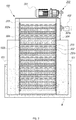
- FIG. 3 is a side elevation view of a waste screening apparatus in accordance with one embodiment of the present disclosure.
- FIG. 4 is a side cross-sectional view of a waste screening apparatus in accordance with one embodiment of the present disclosure.
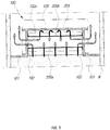
- FIG. 5 is a top cross-sectional view of a waste screening apparatus in accordance with one embodiment of the present disclosure. Referring to FIG. 1 to FIG. 5 , a waste screening apparatus in accordance with one embodiment of the present disclosure will be described in details.
- a present waste screening apparatus may include a main body 100 disposed in a water flow channel in a water treatment plant, wherein the main body 100 is vertically elongate and tilted; a waste screener 200 vertically and tiltedly disposed in the main body 100 to screen wastes in input water and to allow waste-removed water to be discharged through water discharge holes defined in both side faces of the main body 100 respectively, wherein the waste screener 200 vertically circulates in a conveyor manner, wherein the input water is input to a front, rear and bottom of the waste screener 200; a driver 300 to move the waste screener using a roller chain 304; and a brusher 400 disposed to substantially contact a surface of the waste screener 200 to remove a waste from the waste screener 200.
- the main body 100 may include both wing plates 101 disposed at both front sides of the main body 100 respectively, wherein the wing plates 101 are water-tightly coupled to both inner side walls of the water flow channel to guide the input water to the waste screener 200.
- the main body 100 may include both side walls 102 having the water discharge holes 102a defined therein respectively to allow waste-removed water to be discharged out from the waste screener 200 therethrough.
- Gap-blocking brushes 102b may be disposed to block gaps between both sides of the waste screener 200 and corresponding inner side faces of the both side walls 102 respectively.
- the main body 100 may include a rear blocking wall 103 disposed at a rear of the waste screener 200 to be spaced from the waste screener 200.
- the main body 100 may include a waste-discharge port 104 disposed at a top of the main body 100 at a rear of the rear blocking wall 103 to allow wastes filtered by the waste screener 200 to be discharged out therethrough.
- the both wing plates 101 may be disposed at both front sides of the main body 100 respectively.
- the both wing plates 101 may be water-tightly coupled to the inner side walls of the water flow channel.
- the both wing plates 101 may prevent water containing wastes from passing through between the walls of the water flow channel and the main body of the waste screening apparatus. Instead, the both wing plates 101 may guide the water containing wastes to the waste screener 200 at a front thereof. In this way, when the main body 100 is installed in the water flow channel in the water treatment plant, the water flow channel may not have a structural change to be adapted for the main body 100.
- the rear blocking wall 103 may be disposed at a rear of the waste screener 200.
- the rear blocking wall 103 may be spaced from the waste screener 200 to be parallel to the rear portion of the waste screener 200.
- the rear blocking wall 103 may be configured such that the input water inputting to the main body 100 toward the front thereto reversely passes through a rear waste screener portion 200b of the waste screener 200 with the wastes being removed by the rear waste screener portion 200b from the water. That is, the rear blocking wall 103 may allow the input water to flow in a reverse direction opposite a forward direction and to pass through the rear waste screener portion 200b of the waste screener 200. To this end, the rear blocking wall 103 may be formed as a rear portion of the main body 100 to have a vertical height larger than a level of the input water.
- the waste-discharge port 104 may be disposed at a top of the main body 100 at a rear of the rear blocking wall 103 to allow wastes filtered by the waste screener 200 to be discharged out therethrough. In order to prevent the wastes from being scattered, the waste-discharge port 104 may be closed at top and side portions thereof only except for a bottom thereof. Further, below the waste-discharge port 104, a waste conveyor 104a may be disposed to convey the wastes falling down from the waste-discharge port 104 to a waste collection location.
- the both side walls 102 mag be integrated with and disposed between the wing plates 101 and rear blocking wall 103 respectively.
- the waste-removed water from the front waste screener portion 200a and rear waste screener portion 200b of the waste screener 200 may flow into the inner space defined in the waste screener 200 between the front waste screener portion 200a and rear waste screener portion 200b. Then, the waste-removed water may be discharged out through the water discharge holes 102a defined in the both side walls of the main body between the front waste screener portion 200a and rear waste screener portion 200b.
- the waste screener 200 may take an endless conveyor form.
- the water discharge holes 102a may allow first waste-removed water forwardly passing through the front waste screener portion 200a of the waste screener 200 and second waste-removed water reversely passing through the rear waste screener portion 200b of the waste screener 200 to be concurrently discharged out therethrough. This may increase a waste filtering capacity since the front waste screener portion 200a and rear waste screener portion 200b of the waste screener 200 are concurrently used to filter the wastes.
- the gap-blocking brushes 102b may be disposed to block gaps between both sides of the waste screener 200 and corresponding inner side faces of the both side walls 102 respectively.
- various wastes contained in the input water may be prevented from passing through the gaps between both sides of the waste screener 200 and corresponding inner side faces of the both side walls 102 respectively and then being discharged out through the water discharge holes 102a without being filtered out by the waste screener 200.
- the waste screener 200 may have an endless conveyor form.
- the waste screener 200 may have an inner space defined between the rear and front portions thereof.
- the waste screener 200 may be open at both sides thereof.
- the waste screener 200 may extend vertically and tiltedly.
- the waste screener 200 may circulate in an endless manner.
- the waste screener 200 may filter wastes contained in the input water flowing toward a front of the main body 100.
- the waste-removed water may pass through the open both sides of the screener 200.
- the waste screener 200 may include multiple shaft pins 201 coupled to the roller chain 304 wherein the multiple shaft pins 201 are spacedly arranged along the roller chain 304; multiple porous plates 202, each porous plate having a hinge 202a at an vertical end thereof rotatably coupled to the corresponding shaft pin 201, wherein the porous plates 202 are configured to filter the wastes contained in the input water; and multiple hooks 203, each hook extending horizontally from the corresponding hinge 202a to lift up the wastes contained in the input water.
- the multiple shaft pins 201 each may extend horizontally to connect both side roller chains 304 on both inner side faces of the side walls 102 of the main body 100 respectively.
- the multiple shaft pins 201 may be arranged at a predetermined spacing therebetween.
- Each of the porous plates 202 may be coupled to each of the multiple shaft pins 201 via each of the hinges 202a.
- the porous plates 202 may be coupled to one another in a conveyor manner.
- the porous plates 202 may be moved using the roller chain 304.
- the porous plates 202 may be water-tightly coupled to the multiple shaft pins 201 via the hinges 202a thereof respectively. Thus, the waste may not be inserted into the hinges 202a.
- the porous plates 202 coupled to one another in a conveyor manner are circulated using the roller chain 304, the plates may not be spaced from each other at portions of the plates 202 having direction-changes. Thus, the waste may not be fitted with the plates 202.
- a certain porous plate 202 among the porous plates 202 is damaged, only the damaged porous plates 202 may be replaced with new one.
- Each of the porous plates 202 may have fine holes defined therein as shown in FIG. 1 to allow the passage of the water but to disallow the passage of the waste.
- the diameter of each hole defined in the plate 202 may depend on types or sizes or shapes of the wastes contained in the input water into the water flow channel in the water treatment plant where the present waste screening apparatus is installed.
- Each of the hooks 203 may protrude horizontally from each of the hinges 202a of the porous plates 202.
- the hooks 203 may lift up the various wastes removed from the input water.
- the hooks 203 may lift up various settlements on the bottom of the main body 100 such as sludge, rocks, sands, soils, etc. thereby to prevent the bottom of the waste screener 200 from being blocked by the settlements.
- the input water may passes through the bottom of the screener 200.
- Each of the hooks 203 may extend along a width of each of the porous plates 202.
- Each hook 203 may have a plate shape as shown in FIG. 1 . However, the present disclosure may not be limited thereto.
- Each hook 203 may have a cup shape or rake shape.
- the driver 300 may be configured to circulate the waste screener 200 using the roller chains 304.
- the driver 300 may include a driver motor 301 disposed, for example, over the top portion of the main body 100; a driver shaft 302 horizontally axially extending along a width of the screener 200 and disposed, for example, in the top portion of the main body 100, wherein both-sides first sprockets 302a are coupled to the shaft 302 at both ends thereof; a driven shaft 303 horizontally axially extending along a width of the screener 200 and disposed, for example, in the bottom portion of the main body 100, wherein both-sides second sprockets 303a are coupled to the shaft 303 at both ends thereof; and a roller chain 304 coupled between the first sprocket 302a and second sprocket 303a to circulate together with the screener 200.
- the driver motor 301 may supply the rotation force via a belt to the driver shaft 302, which, in turn, transfers the rotation force to both-sides first sprockets 302a, which, in turn, transfer the rotation force to both-sides roller chains 304, which, in turn, transfer the rotation force to the driven shaft 303 via the second sprockets 303a respectively.
- the both-sides roller chains 304 may be coupled to and between the first sprockets 302a and second sprockets 303a respectively. In this way, the driver motor 301 may be configured to rotate the roller chains 304 and, thus, the waste screener 200.
- the brusher 400 may be disposed to substantially contact a surface of the waste screener 200 to remove a waste from the waste screener 200.
- the brusher 400 may be disposed at a rear of the waste screener 200 and in the top portion of the main body 100.
- the brusher 400 may include a brushing roller 401 to substantially contact a surface of the waste screener 200 to remove a waste from the waste screener 200; and a speed reduction motor 402 outside of the main body 100 to rotate the brushing roller 401.
- the brushing roller 401 may have bristles, each bristle having a length larger than a length of each of the hooks 203 protruding from the porous plates 202 of the waste screener 200. Thus, when the waste screener 200 is driven, and the brushing roller 401 rotates to remove the wastes from the surface of the waste screener 200, interference between the hooks 203 and the brushing roller 401 may be suppressed.
- the present waste screening apparatus may be installed in a water flow channel W in a water pumping plant such as an edible water pumping or relay water pumping or water discharge pumping plant, or a water treatment plant such as a sewage treatment plant, waste water treatment plant, etc.
- the present waste screening apparatus may filter or screen the wastes from the input water thereto and discharge the removed wastes out of the water flow channel and allow the waste-removed water to flow through the water flow channel.
- the main body 100 may have the wing plates 101 water-tightly coupled to the inner side faces of the water flow channel. In this way, the main body 100 may be installed in the water flow channel W.
- the input water containing the wastes may be input through the water flow channel to the main body 100 and to the waste screener 200.
- the driver 300 may rotate the waste screener 200 to remove the wastes from the input water flowing in front, rear and bottom directions thereof thereto, while the waste screener 200 allows the passage of the waste-removed water.
- the waste screener 200 may lift up the wastes and discharge the wastes out of the water flow channel.
- the waste-removed water may pass through the holes defined in the porous plates 202 of the waste screener 200 and to the inner space defined between the front and rear portions of the waste screener 200 and then through the water discharge holes 102a defined in the side walls 102 of the main body 100 and, finally, may be discharged out of the present apparatus.
- the waste screener 200 may filter the input water.
- the brusher 400 disposed at a rear of the waste screener 200 may remove the wastes deposited on the surface of the waste screener 200 therefrom.
- the brusher 400 may discharge the waste through the waste discharge port 104 to a waste conveyor 104a which may transfer the waste to the waste collection location. In this way, the brusher 400 may clean the waste screener 200.
- the holes defined in the plates 202 of the waste screener 200 may be prevented from being blocked with the wastes.
Landscapes
- Chemical & Material Sciences (AREA)
- Chemical Kinetics & Catalysis (AREA)
- Engineering & Computer Science (AREA)
- General Engineering & Computer Science (AREA)
- Civil Engineering (AREA)
- Structural Engineering (AREA)
- Mechanical Engineering (AREA)
- Life Sciences & Earth Sciences (AREA)
- Hydrology & Water Resources (AREA)
- Environmental & Geological Engineering (AREA)
- Water Supply & Treatment (AREA)
- Organic Chemistry (AREA)
- Filtration Of Liquid (AREA)
- Analytical Chemistry (AREA)
Applications Claiming Priority (1)
| Application Number | Priority Date | Filing Date | Title |
|---|---|---|---|
| KR1020160022646A KR101648938B1 (ko) | 2016-02-25 | 2016-02-25 | 3방향 스크린 장치 |
Publications (2)
| Publication Number | Publication Date |
|---|---|
| EP3211136A1 true EP3211136A1 (fr) | 2017-08-30 |
| EP3211136B1 EP3211136B1 (fr) | 2018-10-31 |
Family
ID=56875106
Family Applications (1)
| Application Number | Title | Priority Date | Filing Date |
|---|---|---|---|
| EP17153903.4A Active EP3211136B1 (fr) | 2016-02-25 | 2017-01-31 | Appareil de criblage de déchets |
Country Status (6)
| Country | Link |
|---|---|
| US (1) | US10112131B2 (fr) |
| EP (1) | EP3211136B1 (fr) |
| JP (1) | JP6406556B2 (fr) |
| KR (1) | KR101648938B1 (fr) |
| CN (1) | CN107115709B (fr) |
| RU (1) | RU2017102395A (fr) |
Families Citing this family (28)
| Publication number | Priority date | Publication date | Assignee | Title |
|---|---|---|---|---|
| US10233035B2 (en) | 2014-04-10 | 2019-03-19 | Flexible Steel Lacing Company | Conveyor transfer guards |
| KR20240128141A (ko) | 2017-04-10 | 2024-08-23 | 후렉크시불스티일레이싱캄파니 | 이송 가드 시스템, 이송 시스템 및 이송 시스템의 설치 방법 |
| CN106925010A (zh) * | 2017-04-26 | 2017-07-07 | 绍兴市汉工机械有限公司 | 一种定型机自动滤网清理系统 |
| CN108049371A (zh) * | 2017-12-21 | 2018-05-18 | 赵桂金 | 一种水利构筑物进水口挡污装置 |
| CN109224595A (zh) * | 2018-11-27 | 2019-01-18 | 安徽省绿巨人环境技术有限公司 | 一种工业废水残渣高效处理流程工艺 |
| KR102315904B1 (ko) | 2019-07-26 | 2021-10-25 | 주식회사 에싸 | 스크린 및 소독 산화장치를 구비한 병원폐수 처리 시스템 |
| JP6857935B2 (ja) * | 2019-08-07 | 2021-04-14 | コマツオイルフィルターズマレーシア・スンディリアン・ブルハドKomatsu Oil Filters Malaysia Sdn Bhd | 食用油の濾過装置 |
| CN111302510A (zh) * | 2019-11-29 | 2020-06-19 | 盐城集力劳务服务有限公司 | 一种市政工程用污水处理装置 |
| CN111185031A (zh) * | 2020-01-20 | 2020-05-22 | 广州市绿森环保设备有限公司 | 一种多级油水分离器及其控制方法 |
| KR102160894B1 (ko) * | 2020-04-10 | 2020-09-29 | 주식회사 에싸 | 수중이물질을 여과, 분리, 탈수하는 다중구조의 여과장치 |
| CN111643993A (zh) * | 2020-05-01 | 2020-09-11 | 北京点域科技有限公司 | 一种玻璃磨边机用粉尘处理装置 |
| US11633680B2 (en) * | 2020-07-23 | 2023-04-25 | Parkson Corporation | Bar screen filter apparatus and method |
| MX2023003299A (es) | 2020-09-22 | 2023-08-07 | Flexible Steel Lacing Co | Bloqueador de espacios de transportador de rodillos. |
| CN214808992U (zh) * | 2021-01-28 | 2021-11-23 | 桐乡市新时代皮草有限公司 | 一种工业废水处理装置 |
| KR102355047B1 (ko) * | 2021-03-10 | 2022-01-24 | (주)신대양 | 송풍형 경사스키머를 이용한 스컴제거장치 |
| CN113654164B (zh) * | 2021-08-25 | 2022-12-23 | 佛山市香莱诗香薰有限公司 | 一种节能环保空气净化器 |
| CA3232352A1 (fr) | 2021-09-24 | 2023-03-30 | Flexible Steel Lacing Company | Bloqueur d?espace de transporteur a rouleaux |
| KR102601272B1 (ko) * | 2021-11-29 | 2023-11-13 | 정순항 | 협잡물의 이송이 용이한 스크린 장치 및 스크린 장치의 이상동작 대응 방법 |
| CN114272669A (zh) * | 2022-01-17 | 2022-04-05 | 苏州鸿本生物环保科技有限公司 | 一种污水中丝状物去除装置 |
| GB2627107B (en) | 2022-03-03 | 2025-04-16 | Flexible Steel Lacing Co | Conveyor gap blocker |
| USD1064492S1 (en) | 2022-03-04 | 2025-02-25 | Flexible Steel Lacing Company | Conveyor gap blocker |
| CN116803869A (zh) | 2022-03-25 | 2023-09-26 | 弹性钢接头公司 | 输送机传输防护装置 |
| CN114876006B (zh) * | 2022-05-31 | 2024-07-16 | 福建大丰收灌溉科技有限公司 | 一种智能灌溉一体化泵站 |
| KR102481167B1 (ko) * | 2022-06-22 | 2022-12-26 | 주식회사 에싸 | 삼방향종합물질제거기 |
| KR102602296B1 (ko) * | 2022-11-21 | 2023-11-16 | 주식회사에싸 | 대용량의 개선된 3방향 스크린 장치 |
| KR102855401B1 (ko) | 2024-12-11 | 2025-09-05 | 주식회사 에싸 | 면형-라인 세척수 분사 파이프를 구비한 스크린 장치 |
| KR102788668B1 (ko) | 2024-12-11 | 2025-04-02 | 주식회사 에싸 | 자중 간격조절 브러시 어셈블리를 갖는 스크린 장치 |
| CN119909443B (zh) * | 2024-12-27 | 2025-11-21 | 扬州城控排水管网运维有限公司 | 一种基于物联网的智能河道排污口污水截留收集系统 |
Citations (4)
| Publication number | Priority date | Publication date | Assignee | Title |
|---|---|---|---|---|
| FR600111A (fr) * | 1925-06-26 | 1926-01-30 | Appareil d'épuration mécanique de l'eau | |
| US5800701A (en) * | 1994-05-25 | 1998-09-01 | I. Kruger Systems A/S | Apparatus, components and a method for the filtering of liquid |
| KR200244906Y1 (ko) | 1999-04-02 | 2001-09-25 | 조현준 | 오. 폐수 처리용 자동 바 스크린장치 |
| KR100941622B1 (ko) | 2008-04-15 | 2010-02-11 | 조창균 | 조립형 무빙스크린장치 |
Family Cites Families (24)
| Publication number | Priority date | Publication date | Assignee | Title |
|---|---|---|---|---|
| FR577255A (fr) * | 1924-02-16 | 1924-09-03 | Beaudrey Et Bergeron | Perfectionnements aux grilles de prise d'eau à marche mécanique |
| US1789425A (en) * | 1928-05-05 | 1931-01-20 | Electro Dialyzer Corp | Filtration process and apparatus |
| JPS4914570U (fr) * | 1972-05-11 | 1974-02-06 | ||
| JPS5038477Y2 (fr) * | 1973-06-13 | 1975-11-07 | ||
| US4188294A (en) * | 1978-05-18 | 1980-02-12 | Tadashi Hagihara | Rotary filter apparatus |
| FR2477195A1 (fr) * | 1980-03-03 | 1981-09-04 | Beaudrey & Cie | Filtre a chaine a double flux, et procede pour sa substitution a un filtre a chaine a passage direct |
| US4892652A (en) * | 1988-07-22 | 1990-01-09 | Fmc Corporation | Curved diverter plate assembly for interchangeability of various models of traveling water screens |
| DE9104551U1 (de) * | 1991-04-13 | 1991-06-06 | Bormet, Horst, 6108 Weiterstadt | Siebrechen |
| EP0676226A1 (fr) * | 1994-04-08 | 1995-10-11 | Dieter Frankenberger | Dispositif de filtration en forme d'une bande transporteuse |
| JPH0833807A (ja) * | 1994-07-25 | 1996-02-06 | Hitachi Kiden Kogyo Ltd | スクリーン移動式除塵機 |
| GB9503340D0 (en) * | 1995-02-21 | 1995-04-12 | Jones & Attwood Ltd | Screen |
| JP3049482U (ja) * | 1997-12-04 | 1998-06-09 | 建 信 柯 | 自浄可能な濾過装置 |
| DE19814140C1 (de) * | 1998-03-30 | 1999-11-11 | Noggerath Holding Gmbh Co Kg | Umlauf-Siebrechen, Tragrahmen für einen Umlauf-Siebrechen und Steuerlasche eines Siebelements |
| JP2002069974A (ja) * | 2000-08-28 | 2002-03-08 | Marsima Aqua System Corp | 除塵装置 |
| GB2407782B (en) * | 2001-08-29 | 2005-09-28 | Brackett Green Ltd | A band screen assembly |
| DE10325115A1 (de) * | 2003-06-02 | 2004-12-23 | Hans Huber Ag Maschinen- Und Anlagenbau | Vorrichtung zum Abscheiden und Abtransport von Abscheidegut |
| DE102004014022A1 (de) * | 2004-03-19 | 2005-10-06 | Grammelsberger, Axel, Dipl.-Ing. (FH) | Siebrechen |
| KR100642815B1 (ko) * | 2005-09-28 | 2006-11-03 | (주)정봉 | 스크린장치 |
| US7776212B2 (en) * | 2006-03-14 | 2010-08-17 | Laitram, L.L.C. | Water screen system with boot seal |
| JP4750050B2 (ja) * | 2007-02-02 | 2011-08-17 | 株式会社日立プラントテクノロジー | スクリーン循環式除塵機 |
| EP2335795B1 (fr) * | 2009-12-15 | 2013-02-13 | Guido Frankenberger | Dispositif de filtre à bande de transport |
| KR101177922B1 (ko) * | 2011-08-09 | 2012-08-29 | 주식회사 엠에스테크 | 제진기 |
| CN102553329B (zh) * | 2012-01-22 | 2014-07-09 | 江苏一环集团有限公司 | 水处理用回转细格栅及在水处理中的应用 |
| KR101415953B1 (ko) * | 2012-11-05 | 2014-07-04 | 주식회사 에싸 | 물의 흐름에 영향을 주지 않는 제진기 |
-
2016
- 2016-02-25 KR KR1020160022646A patent/KR101648938B1/ko active Active
-
2017
- 2017-01-20 US US15/411,825 patent/US10112131B2/en active Active
- 2017-01-24 CN CN201710053028.5A patent/CN107115709B/zh active Active
- 2017-01-25 RU RU2017102395A patent/RU2017102395A/ru unknown
- 2017-01-27 JP JP2017012632A patent/JP6406556B2/ja active Active
- 2017-01-31 EP EP17153903.4A patent/EP3211136B1/fr active Active
Patent Citations (4)
| Publication number | Priority date | Publication date | Assignee | Title |
|---|---|---|---|---|
| FR600111A (fr) * | 1925-06-26 | 1926-01-30 | Appareil d'épuration mécanique de l'eau | |
| US5800701A (en) * | 1994-05-25 | 1998-09-01 | I. Kruger Systems A/S | Apparatus, components and a method for the filtering of liquid |
| KR200244906Y1 (ko) | 1999-04-02 | 2001-09-25 | 조현준 | 오. 폐수 처리용 자동 바 스크린장치 |
| KR100941622B1 (ko) | 2008-04-15 | 2010-02-11 | 조창균 | 조립형 무빙스크린장치 |
Also Published As
| Publication number | Publication date |
|---|---|
| US20170246564A1 (en) | 2017-08-31 |
| US10112131B2 (en) | 2018-10-30 |
| RU2017102395A (ru) | 2018-07-26 |
| JP6406556B2 (ja) | 2018-10-17 |
| KR101648938B1 (ko) | 2016-08-19 |
| CN107115709B (zh) | 2019-04-12 |
| RU2017102395A3 (fr) | 2018-07-26 |
| EP3211136B1 (fr) | 2018-10-31 |
| JP2017148794A (ja) | 2017-08-31 |
| CN107115709A (zh) | 2017-09-01 |
Similar Documents
| Publication | Publication Date | Title |
|---|---|---|
| US10112131B2 (en) | Waste screening apparatus | |
| US9415475B2 (en) | Conveyer apparatus for discharging chips | |
| KR101893203B1 (ko) | 스프링캡 내장형 레이크를 구비한 협잡물 제거용 스크린 | |
| CN218458748U (zh) | 具有自清洁功能的化工废水过滤装置 | |
| KR200437204Y1 (ko) | 부상식 차단부를 갖는 다단식 로터리 제진기 | |
| KR101203002B1 (ko) | 수처리시설의 스컴스키머장치 | |
| CN113413674A (zh) | 一种具有水循环过滤功能的污水处理设备 | |
| KR100902816B1 (ko) | 오폐수 처리용 자동 바 스크린 장치 | |
| KR101473166B1 (ko) | 수로 스크린 협잡물 처리시스템 | |
| CN107754391A (zh) | 一种往复一体式污水处理沉淀池 | |
| KR100945281B1 (ko) | 수처리장의 무빙 스크린 | |
| CN216664291U (zh) | 一种废水处理池用池底清淤装置 | |
| CN215359365U (zh) | 一种新型塑料制品回收清洗船 | |
| KR100959361B1 (ko) | 원수 혼입방지 슬러지 배출시스템 | |
| KR20110092024A (ko) | 게이트 펌프용 로터리 제진기 | |
| JP3762338B2 (ja) | 洗浄水自動供給スクリーン | |
| CN210406724U (zh) | 一种水产养殖池水循环用过滤装置 | |
| DE102010034098A1 (de) | Siebrechenvorrichtungen und Verwendung | |
| CN214271685U (zh) | 一种桥梁用排水装置 | |
| CN215399227U (zh) | 一种节水型塑料制品回收清洗船 | |
| KR200381939Y1 (ko) | 협잡물 제거용 로타리 자동스크린 | |
| CN116770788A (zh) | 一种带有清理功能的水利闸门 | |
| CN207531699U (zh) | 一种渔业养殖用优化水质时避免堵塞的装置 | |
| CN116639781A (zh) | 一种基于自净技术的水处理设备 | |
| CN212832888U (zh) | 一种机械格栅机 |
Legal Events
| Date | Code | Title | Description |
|---|---|---|---|
| PUAI | Public reference made under article 153(3) epc to a published international application that has entered the european phase |
Free format text: ORIGINAL CODE: 0009012 |
|
| STAA | Information on the status of an ep patent application or granted ep patent |
Free format text: STATUS: REQUEST FOR EXAMINATION WAS MADE |
|
| 17P | Request for examination filed |
Effective date: 20170131 |
|
| AK | Designated contracting states |
Kind code of ref document: A1 Designated state(s): AL AT BE BG CH CY CZ DE DK EE ES FI FR GB GR HR HU IE IS IT LI LT LU LV MC MK MT NL NO PL PT RO RS SE SI SK SM TR |
|
| AX | Request for extension of the european patent |
Extension state: BA ME |
|
| RBV | Designated contracting states (corrected) |
Designated state(s): AL AT BE BG CH CY CZ DE DK EE ES FI FR GB GR HR HU IE IS IT LI LT LU LV MC MK MT NL NO PL PT RO RS SE SI SK SM TR |
|
| GRAP | Despatch of communication of intention to grant a patent |
Free format text: ORIGINAL CODE: EPIDOSNIGR1 |
|
| STAA | Information on the status of an ep patent application or granted ep patent |
Free format text: STATUS: GRANT OF PATENT IS INTENDED |
|
| INTG | Intention to grant announced |
Effective date: 20180516 |
|
| GRAS | Grant fee paid |
Free format text: ORIGINAL CODE: EPIDOSNIGR3 |
|
| GRAA | (expected) grant |
Free format text: ORIGINAL CODE: 0009210 |
|
| STAA | Information on the status of an ep patent application or granted ep patent |
Free format text: STATUS: THE PATENT HAS BEEN GRANTED |
|
| AK | Designated contracting states |
Kind code of ref document: B1 Designated state(s): AL AT BE BG CH CY CZ DE DK EE ES FI FR GB GR HR HU IE IS IT LI LT LU LV MC MK MT NL NO PL PT RO RS SE SI SK SM TR |
|
| REG | Reference to a national code |
Ref country code: CH Ref legal event code: EP Ref country code: GB Ref legal event code: FG4D |
|
| REG | Reference to a national code |
Ref country code: AT Ref legal event code: REF Ref document number: 1059543 Country of ref document: AT Kind code of ref document: T Effective date: 20181115 |
|
| REG | Reference to a national code |
Ref country code: DE Ref legal event code: R096 Ref document number: 602017000725 Country of ref document: DE |
|
| REG | Reference to a national code |
Ref country code: IE Ref legal event code: FG4D |
|
| REG | Reference to a national code |
Ref country code: NL Ref legal event code: MP Effective date: 20181031 |
|
| REG | Reference to a national code |
Ref country code: LT Ref legal event code: MG4D |
|
| REG | Reference to a national code |
Ref country code: AT Ref legal event code: MK05 Ref document number: 1059543 Country of ref document: AT Kind code of ref document: T Effective date: 20181031 |
|
| PG25 | Lapsed in a contracting state [announced via postgrant information from national office to epo] |
Ref country code: ES Free format text: LAPSE BECAUSE OF FAILURE TO SUBMIT A TRANSLATION OF THE DESCRIPTION OR TO PAY THE FEE WITHIN THE PRESCRIBED TIME-LIMIT Effective date: 20181031 Ref country code: LV Free format text: LAPSE BECAUSE OF FAILURE TO SUBMIT A TRANSLATION OF THE DESCRIPTION OR TO PAY THE FEE WITHIN THE PRESCRIBED TIME-LIMIT Effective date: 20181031 Ref country code: PL Free format text: LAPSE BECAUSE OF FAILURE TO SUBMIT A TRANSLATION OF THE DESCRIPTION OR TO PAY THE FEE WITHIN THE PRESCRIBED TIME-LIMIT Effective date: 20181031 Ref country code: HR Free format text: LAPSE BECAUSE OF FAILURE TO SUBMIT A TRANSLATION OF THE DESCRIPTION OR TO PAY THE FEE WITHIN THE PRESCRIBED TIME-LIMIT Effective date: 20181031 Ref country code: BG Free format text: LAPSE BECAUSE OF FAILURE TO SUBMIT A TRANSLATION OF THE DESCRIPTION OR TO PAY THE FEE WITHIN THE PRESCRIBED TIME-LIMIT Effective date: 20190131 Ref country code: NO Free format text: LAPSE BECAUSE OF FAILURE TO SUBMIT A TRANSLATION OF THE DESCRIPTION OR TO PAY THE FEE WITHIN THE PRESCRIBED TIME-LIMIT Effective date: 20190131 Ref country code: LT Free format text: LAPSE BECAUSE OF FAILURE TO SUBMIT A TRANSLATION OF THE DESCRIPTION OR TO PAY THE FEE WITHIN THE PRESCRIBED TIME-LIMIT Effective date: 20181031 Ref country code: FI Free format text: LAPSE BECAUSE OF FAILURE TO SUBMIT A TRANSLATION OF THE DESCRIPTION OR TO PAY THE FEE WITHIN THE PRESCRIBED TIME-LIMIT Effective date: 20181031 Ref country code: AT Free format text: LAPSE BECAUSE OF FAILURE TO SUBMIT A TRANSLATION OF THE DESCRIPTION OR TO PAY THE FEE WITHIN THE PRESCRIBED TIME-LIMIT Effective date: 20181031 Ref country code: IS Free format text: LAPSE BECAUSE OF FAILURE TO SUBMIT A TRANSLATION OF THE DESCRIPTION OR TO PAY THE FEE WITHIN THE PRESCRIBED TIME-LIMIT Effective date: 20190228 |
|
| PG25 | Lapsed in a contracting state [announced via postgrant information from national office to epo] |
Ref country code: NL Free format text: LAPSE BECAUSE OF FAILURE TO SUBMIT A TRANSLATION OF THE DESCRIPTION OR TO PAY THE FEE WITHIN THE PRESCRIBED TIME-LIMIT Effective date: 20181031 Ref country code: GR Free format text: LAPSE BECAUSE OF FAILURE TO SUBMIT A TRANSLATION OF THE DESCRIPTION OR TO PAY THE FEE WITHIN THE PRESCRIBED TIME-LIMIT Effective date: 20190201 Ref country code: RS Free format text: LAPSE BECAUSE OF FAILURE TO SUBMIT A TRANSLATION OF THE DESCRIPTION OR TO PAY THE FEE WITHIN THE PRESCRIBED TIME-LIMIT Effective date: 20181031 Ref country code: SE Free format text: LAPSE BECAUSE OF FAILURE TO SUBMIT A TRANSLATION OF THE DESCRIPTION OR TO PAY THE FEE WITHIN THE PRESCRIBED TIME-LIMIT Effective date: 20181031 Ref country code: PT Free format text: LAPSE BECAUSE OF FAILURE TO SUBMIT A TRANSLATION OF THE DESCRIPTION OR TO PAY THE FEE WITHIN THE PRESCRIBED TIME-LIMIT Effective date: 20190301 Ref country code: AL Free format text: LAPSE BECAUSE OF FAILURE TO SUBMIT A TRANSLATION OF THE DESCRIPTION OR TO PAY THE FEE WITHIN THE PRESCRIBED TIME-LIMIT Effective date: 20181031 |
|
| PG25 | Lapsed in a contracting state [announced via postgrant information from national office to epo] |
Ref country code: CZ Free format text: LAPSE BECAUSE OF FAILURE TO SUBMIT A TRANSLATION OF THE DESCRIPTION OR TO PAY THE FEE WITHIN THE PRESCRIBED TIME-LIMIT Effective date: 20181031 Ref country code: DK Free format text: LAPSE BECAUSE OF FAILURE TO SUBMIT A TRANSLATION OF THE DESCRIPTION OR TO PAY THE FEE WITHIN THE PRESCRIBED TIME-LIMIT Effective date: 20181031 Ref country code: IT Free format text: LAPSE BECAUSE OF FAILURE TO SUBMIT A TRANSLATION OF THE DESCRIPTION OR TO PAY THE FEE WITHIN THE PRESCRIBED TIME-LIMIT Effective date: 20181031 |
|
| REG | Reference to a national code |
Ref country code: DE Ref legal event code: R097 Ref document number: 602017000725 Country of ref document: DE |
|
| PG25 | Lapsed in a contracting state [announced via postgrant information from national office to epo] |
Ref country code: SK Free format text: LAPSE BECAUSE OF FAILURE TO SUBMIT A TRANSLATION OF THE DESCRIPTION OR TO PAY THE FEE WITHIN THE PRESCRIBED TIME-LIMIT Effective date: 20181031 Ref country code: RO Free format text: LAPSE BECAUSE OF FAILURE TO SUBMIT A TRANSLATION OF THE DESCRIPTION OR TO PAY THE FEE WITHIN THE PRESCRIBED TIME-LIMIT Effective date: 20181031 Ref country code: MC Free format text: LAPSE BECAUSE OF FAILURE TO SUBMIT A TRANSLATION OF THE DESCRIPTION OR TO PAY THE FEE WITHIN THE PRESCRIBED TIME-LIMIT Effective date: 20181031 Ref country code: EE Free format text: LAPSE BECAUSE OF FAILURE TO SUBMIT A TRANSLATION OF THE DESCRIPTION OR TO PAY THE FEE WITHIN THE PRESCRIBED TIME-LIMIT Effective date: 20181031 Ref country code: SM Free format text: LAPSE BECAUSE OF FAILURE TO SUBMIT A TRANSLATION OF THE DESCRIPTION OR TO PAY THE FEE WITHIN THE PRESCRIBED TIME-LIMIT Effective date: 20181031 |
|
| PLBE | No opposition filed within time limit |
Free format text: ORIGINAL CODE: 0009261 |
|
| STAA | Information on the status of an ep patent application or granted ep patent |
Free format text: STATUS: NO OPPOSITION FILED WITHIN TIME LIMIT |
|
| PG25 | Lapsed in a contracting state [announced via postgrant information from national office to epo] |
Ref country code: LU Free format text: LAPSE BECAUSE OF NON-PAYMENT OF DUE FEES Effective date: 20190131 |
|
| 26N | No opposition filed |
Effective date: 20190801 |
|
| REG | Reference to a national code |
Ref country code: BE Ref legal event code: MM Effective date: 20190131 |
|
| REG | Reference to a national code |
Ref country code: IE Ref legal event code: MM4A |
|
| PG25 | Lapsed in a contracting state [announced via postgrant information from national office to epo] |
Ref country code: SI Free format text: LAPSE BECAUSE OF FAILURE TO SUBMIT A TRANSLATION OF THE DESCRIPTION OR TO PAY THE FEE WITHIN THE PRESCRIBED TIME-LIMIT Effective date: 20181031 |
|
| PG25 | Lapsed in a contracting state [announced via postgrant information from national office to epo] |
Ref country code: BE Free format text: LAPSE BECAUSE OF NON-PAYMENT OF DUE FEES Effective date: 20190131 |
|
| PG25 | Lapsed in a contracting state [announced via postgrant information from national office to epo] |
Ref country code: IE Free format text: LAPSE BECAUSE OF NON-PAYMENT OF DUE FEES Effective date: 20190131 |
|
| PG25 | Lapsed in a contracting state [announced via postgrant information from national office to epo] |
Ref country code: TR Free format text: LAPSE BECAUSE OF FAILURE TO SUBMIT A TRANSLATION OF THE DESCRIPTION OR TO PAY THE FEE WITHIN THE PRESCRIBED TIME-LIMIT Effective date: 20181031 |
|
| PG25 | Lapsed in a contracting state [announced via postgrant information from national office to epo] |
Ref country code: MT Free format text: LAPSE BECAUSE OF NON-PAYMENT OF DUE FEES Effective date: 20190131 |
|
| REG | Reference to a national code |
Ref country code: CH Ref legal event code: PL |
|
| PG25 | Lapsed in a contracting state [announced via postgrant information from national office to epo] |
Ref country code: LI Free format text: LAPSE BECAUSE OF NON-PAYMENT OF DUE FEES Effective date: 20200131 Ref country code: CH Free format text: LAPSE BECAUSE OF NON-PAYMENT OF DUE FEES Effective date: 20200131 |
|
| PG25 | Lapsed in a contracting state [announced via postgrant information from national office to epo] |
Ref country code: CY Free format text: LAPSE BECAUSE OF FAILURE TO SUBMIT A TRANSLATION OF THE DESCRIPTION OR TO PAY THE FEE WITHIN THE PRESCRIBED TIME-LIMIT Effective date: 20181031 |
|
| PG25 | Lapsed in a contracting state [announced via postgrant information from national office to epo] |
Ref country code: HU Free format text: LAPSE BECAUSE OF FAILURE TO SUBMIT A TRANSLATION OF THE DESCRIPTION OR TO PAY THE FEE WITHIN THE PRESCRIBED TIME-LIMIT; INVALID AB INITIO Effective date: 20170131 |
|
| PG25 | Lapsed in a contracting state [announced via postgrant information from national office to epo] |
Ref country code: MK Free format text: LAPSE BECAUSE OF FAILURE TO SUBMIT A TRANSLATION OF THE DESCRIPTION OR TO PAY THE FEE WITHIN THE PRESCRIBED TIME-LIMIT Effective date: 20181031 |
|
| PGFP | Annual fee paid to national office [announced via postgrant information from national office to epo] |
Ref country code: GB Payment date: 20260128 Year of fee payment: 10 |
|
| PGFP | Annual fee paid to national office [announced via postgrant information from national office to epo] |
Ref country code: DE Payment date: 20260130 Year of fee payment: 10 |
|
| PGFP | Annual fee paid to national office [announced via postgrant information from national office to epo] |
Ref country code: FR Payment date: 20260129 Year of fee payment: 10 |