EP3211142A2 - Système de fixation de chargeur - Google Patents
Système de fixation de chargeur Download PDFInfo
- Publication number
- EP3211142A2 EP3211142A2 EP17157410.6A EP17157410A EP3211142A2 EP 3211142 A2 EP3211142 A2 EP 3211142A2 EP 17157410 A EP17157410 A EP 17157410A EP 3211142 A2 EP3211142 A2 EP 3211142A2
- Authority
- EP
- European Patent Office
- Prior art keywords
- loader
- mast
- mount
- pawl
- release handle
- Prior art date
- Legal status (The legal status is an assumption and is not a legal conclusion. Google has not performed a legal analysis and makes no representation as to the accuracy of the status listed.)
- Withdrawn
Links
- 230000009471 action Effects 0.000 description 21
- 238000000034 method Methods 0.000 description 13
- 230000008569 process Effects 0.000 description 13
- 108010066278 cabin-4 Proteins 0.000 description 9
- 238000013459 approach Methods 0.000 description 3
- 230000008602 contraction Effects 0.000 description 2
- 230000005484 gravity Effects 0.000 description 2
- 238000005452 bending Methods 0.000 description 1
- 230000008859 change Effects 0.000 description 1
- 239000012530 fluid Substances 0.000 description 1
- 238000004519 manufacturing process Methods 0.000 description 1
- 239000000463 material Substances 0.000 description 1
- 230000007246 mechanism Effects 0.000 description 1
- 238000012986 modification Methods 0.000 description 1
- 230000004048 modification Effects 0.000 description 1
- 230000002093 peripheral effect Effects 0.000 description 1
- 230000009467 reduction Effects 0.000 description 1
- 239000004576 sand Substances 0.000 description 1
- 238000003466 welding Methods 0.000 description 1
Images


Classifications
-
- E—FIXED CONSTRUCTIONS
- E02—HYDRAULIC ENGINEERING; FOUNDATIONS; SOIL SHIFTING
- E02F—DREDGING; SOIL-SHIFTING
- E02F3/00—Dredgers; Soil-shifting machines
- E02F3/04—Dredgers; Soil-shifting machines mechanically-driven
- E02F3/627—Devices to connect beams or arms to tractors or similar self-propelled machines, e.g. drives therefor
- E02F3/6273—Devices to connect beams or arms to tractors or similar self-propelled machines, e.g. drives therefor using legs to support the beams or arms on the ground during the connecting process
-
- E—FIXED CONSTRUCTIONS
- E02—HYDRAULIC ENGINEERING; FOUNDATIONS; SOIL SHIFTING
- E02F—DREDGING; SOIL-SHIFTING
- E02F3/00—Dredgers; Soil-shifting machines
- E02F3/04—Dredgers; Soil-shifting machines mechanically-driven
- E02F3/28—Dredgers; Soil-shifting machines mechanically-driven with digging tools mounted on a dipper- or bucket-arm, i.e. there is either one arm or a pair of arms, e.g. dippers, buckets
- E02F3/36—Component parts
- E02F3/3604—Devices to connect tools to arms, booms or the like
- E02F3/3609—Devices to connect tools to arms, booms or the like of the quick acting type, e.g. controlled from the operator seat
- E02F3/3645—Devices to connect tools to arms, booms or the like of the quick acting type, e.g. controlled from the operator seat with auto-engagement means for automatic snap-on of the tool coupler part
-
- E—FIXED CONSTRUCTIONS
- E02—HYDRAULIC ENGINEERING; FOUNDATIONS; SOIL SHIFTING
- E02F—DREDGING; SOIL-SHIFTING
- E02F3/00—Dredgers; Soil-shifting machines
- E02F3/04—Dredgers; Soil-shifting machines mechanically-driven
- E02F3/28—Dredgers; Soil-shifting machines mechanically-driven with digging tools mounted on a dipper- or bucket-arm, i.e. there is either one arm or a pair of arms, e.g. dippers, buckets
- E02F3/36—Component parts
- E02F3/3604—Devices to connect tools to arms, booms or the like
- E02F3/3609—Devices to connect tools to arms, booms or the like of the quick acting type, e.g. controlled from the operator seat
- E02F3/3668—Devices to connect tools to arms, booms or the like of the quick acting type, e.g. controlled from the operator seat where engagement is effected by a mechanical lever or handle
-
- E—FIXED CONSTRUCTIONS
- E02—HYDRAULIC ENGINEERING; FOUNDATIONS; SOIL SHIFTING
- E02F—DREDGING; SOIL-SHIFTING
- E02F3/00—Dredgers; Soil-shifting machines
- E02F3/04—Dredgers; Soil-shifting machines mechanically-driven
- E02F3/28—Dredgers; Soil-shifting machines mechanically-driven with digging tools mounted on a dipper- or bucket-arm, i.e. there is either one arm or a pair of arms, e.g. dippers, buckets
- E02F3/36—Component parts
- E02F3/3604—Devices to connect tools to arms, booms or the like
- E02F3/3609—Devices to connect tools to arms, booms or the like of the quick acting type, e.g. controlled from the operator seat
- E02F3/3672—Devices to connect tools to arms, booms or the like of the quick acting type, e.g. controlled from the operator seat where disengagement is effected by a mechanical lever or handle
-
- E—FIXED CONSTRUCTIONS
- E02—HYDRAULIC ENGINEERING; FOUNDATIONS; SOIL SHIFTING
- E02F—DREDGING; SOIL-SHIFTING
- E02F3/00—Dredgers; Soil-shifting machines
- E02F3/04—Dredgers; Soil-shifting machines mechanically-driven
- E02F3/28—Dredgers; Soil-shifting machines mechanically-driven with digging tools mounted on a dipper- or bucket-arm, i.e. there is either one arm or a pair of arms, e.g. dippers, buckets
- E02F3/36—Component parts
- E02F3/3695—Arrangements for connecting dipper-arms to loaders or graders
-
- E—FIXED CONSTRUCTIONS
- E02—HYDRAULIC ENGINEERING; FOUNDATIONS; SOIL SHIFTING
- E02F—DREDGING; SOIL-SHIFTING
- E02F3/00—Dredgers; Soil-shifting machines
- E02F3/04—Dredgers; Soil-shifting machines mechanically-driven
- E02F3/96—Dredgers; Soil-shifting machines mechanically-driven with arrangements for alternate or simultaneous use of different digging elements
- E02F3/968—Storing, handling or otherwise manipulating tools when detached from the machine
Definitions
- the present invention relates to a loader attachment system for detachably attaching a loader, e.g., a front end loader, to a vehicle, e.g., a tractor.
- a loader e.g., a front end loader
- each of the masts has an arm cylinder pivot shaft onto which a tip of a piston rod of the arm cylinder is pivoted.
- a latching arm formed with a hook is also pivotally provided on the arm cylinder pivot shaft.
- a torsion spring is interposed between the latching arm and the mast.
- each of the loader mounts includes upper and lower bushed pins.
- the lower bushed pin serves as a pivot for rotating the mast relative to the loader mount.
- the upper bushed pin serves as a latched pin onto which the hook of the latching arm is hooked to lock the mast to the loader mount.
- the front end loader To attach the masts of the front end loader (with the bucket) to the loader mounts of the tractor, the front end loader is previously set so that the bucket, mounted on the front end of the front end loader, and a parking stand, extended forward and downward from the masts, are placed on the ground. Then, the tractor approaches the placed front end loader and stops. Hydraulic pipes are provided to fluidly connect the hydraulic actuators of the front end loader to the tractor. An operator seated on the tractor operates to contract piston rods of the arm cylinders so that the lower bushed pins of the loader mounts are received by respective receptacles formed on bottom edges of the right and left masts.
- the piston rods of the arm cylinders are further contracted to rotate the masts centered on axes of the lower bushed pins relative to the loader mounts so as to lift the parking stand upward apart from the ground.
- the contraction of the piston rods of the arm cylinders cause overcenter action of the torsion springs and location of the latching arms at their latching positions. Therefore, finally, the latching arms are biased by the torsion springs so as to be hooked on the upper bushed pins of the loader mounts, thereby completing the attachment of the masts of the front end loader to the loader mounts of the tractor.
- the seated operator operates the front end loader to place the bucket on the ground, and the operator operates toe pad portions of the latching arms with his/her foot so as to forcedly disengage the latching arms from the upper bushed pins.
- the latching arm rotates around the axis of the arm cylinder pivot shaft against the force of the torsion spring biasing the latching arm to the latching position.
- the spring comes to bias the latching arm to its unlatching position, where the latching arm abuts against a part of the piston rod of the arm cylinder, thereby easily completing the disengagement of the masts from the loader mounts.
- the seated operator operates to extend the piston rods of the arm cylinders to rotate the masts relative to the loader mounts so that the receptacles of the masts can easily be separated from the lower bushed pins of the loader mounts.
- the latching of the masts to the loader mounts via the latching arms relies on the telescopic operation of the piston rods of arm cylinders.
- the upper bushed pin of each loader mount defines both the latching position of the latching arm and the attachment position of the mast relative to the loader mount.
- both the location of the masts relative to the loader mounts and the latching of the masts to the loader mounts depend on the rotation of the masts relative to the loader mounts centered on the lower bushed pins.
- Such a structure seems to require a great accuracy in dimensioning of the latching arms in shape and location relative to both the upper and lower bushed pins so as to increase manufacturing costs.
- each latching arm of the front end loader is formed with the toe pad portion suitable for operation by an operator sitting on the seat or standing on the platform, so that it seems to be hard for a person, who stands beside the tractor (i.e., does not ride the tractor), to access and operate the latching arm for unlatching the latching arm from the upper bushed pin. Therefore, to provide a loader attachment system adaptable to a cabin tractor, the loader attachment system should have a structure enabling an operator outside of a cabin to operate for unlocking masts from loader mounts.
- An object of the invention is to provide a reasonable and useful loader attachment system for detachably attaching a mast of a loader, e.g., a front end loader, to a loader mount of a vehicle, e.g., a tractor, especially, a cabin tractor.
- a loader e.g., a front end loader
- a loader mount of a vehicle e.g., a tractor, especially, a cabin tractor.
- a loader attachment system includes a loader mount fixed on a vehicle, and a mast of a loader to be detachably attached to the loader mount.
- the loader attachment system further includes a support device, a location device and an engagement device.
- the support device is configured to support the mast on the loader mount so that the mast is rotatable relative to the loader mount.
- the location device is configured to locate the mast supported on the loader mount by the support device at an attachment position.
- the engagement device is configured to engage the mast at the attachment position with the loader mount so as to prevent the mast from rotating in a direction to detach the mast from the loader mount.
- the support device, the location device and the engagement device are configured independent of one another.
- the support device, the location device and the engagement device can each have a simple and economic structure.
- the location device and the engagement device can be simplified because each of them does not have to be configured to have the function of the other.
- the support device includes a pivot and a receptacle receiving the pivot.
- the pivot serves as a fulcrum of the rotation of the mast relative to the loader mount.
- One of the loader mount and the mast includes the pivot, and the other of the loader mount and the mast includes the receptacle.
- the location device includes a projection and a groove. The groove is extended along a locus of the projection during the rotation of the mast relative to the loader mount.
- One of the loader mount and the mast includes the projection, and the other of the loader mount and the mast includes the groove.
- the rotation of the mast relative to the loader mount moves the projection in the groove. A position where the projection abuts against a deep end of the groove is defined as the attachment position.
- the location device is simplified so that it includes only the projection and the groove because it does not have the function of the engagement device.
- the engagement device includes a tooth provided on the loader mount, a pawl pivoted on the mast, an overcenter spring interposed between the pawl and the mast, and a release handle pivoted on the mast so that the pawl and the release handle are rotatably centered on a common axis.
- the release handle is rotatable from a lock position to engage the pawl with the tooth.
- the spring biases the pawl in a direction to engage the pawl with the tooth.
- the pawl rotates around the common axis, and the overcenter spring changes a direction of its force so as to bias the pawl in another direction to rotate the pawl apart from the tooth, thereby keeping the pawl disengaged from the tooth.
- the operator's manipulation force can be reduced in both the rotation of the pawl for engaging with the tooth and the rotation of the pawl for disengaging from the tooth. Further, the manipulation of the release handle with the operator's hand is easier than manipulation by use of an operator's foot.
- the release handle is disposed at a right or left outside of the mast.
- an operator can have a sufficient space for operating the release handle the right or left outside of the mast freely from uneasiness. Especially, if a cabin tractor employs this loader attachment system, an operator outside a cabin can easily access the release handle. Further, if the mast is made of transparent or semitransparent material, the rotational position of the pawl may be further clearly visible.
- the loader when the mast is attached to the loader mount, the loader is disposed forward or rearward from the vehicle, and the lock position is forward or rearward close to the loader so that the rotation direction of the release handle from the lock position is forward or rearward away from the loader.
- the lock position and the rotational direction of the release handle are set to match with the operator's sense that defines the direction close to the loader as the direction for locking the mast of the loader, thereby preventing an operator's operational error.
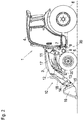
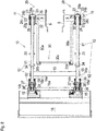
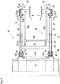
- a tractor 1 includes a vehicle body frame (chassis) 2 having a pair of right and left vertical side plates extended in the fore-and-aft direction of tractor 1.
- a hood 3 is mounted on a front half portion of vehicle body frame 2 so as to accommodate an engine and so on.
- a cabin 4 incorporating an operator's seat is mounted on a rear half portion of vehicle body frame 2.
- a front portion of vehicle body frame 2 supports a pair of right and left front wheels 5.
- a rear portion of vehicle body frame 2 supports a pair of right and left rear wheels 6.
- a pair of right and left loader mounts 7 are fixed on the respective right and left side plates of vehicle body frame 2 immediately forward from a front end of cabin 4 and immediately rearward from respective right and left front wheels 5. More specifically, a stay 9 is stuck to each of the right and left side plates of vehicle body frame 2 and is fastened to the side plate via bolts or so on. A support shaft 8 is extended laterally distally from stay 9.
- Each loader mount 7 is fixed at a lower portion thereof on a distal end of support shaft 8 so as to be spaced laterally distally from vehicle body frame 2 and hood 3, thereby ensuring a space on each of right and left distal sides of hood 3 for arranging each of right and left parts of a front end loader 10, e.g., each of later-discussed arms 12 and each of later-discussed arm cylinders 17.
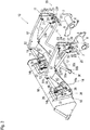
- Front end loader 10 is an assembly including a pair of right and left masts 11, a pair of right and left arms 12, a connection shaft 13, a pair of right and left bucket links 14, a bucket bracket 15, a bucket 16 serving as a kind of work instrument, a pair of right and left arm cylinders 17, a pair of right and left bucket cylinders 18, and a parking stand 19.
- the following description of various parts of front end loader 10 will be based on an assumption that bucket 16 attached to front end loader 10 is grounded, i.e., front end loader 10 is lowered to place bucket 16 at its lowest position.
- Front end loader 10 is attached to tractor 1 by attaching right and left masts 11 of front end loader 10 to respective right and left loader mounts 7 fixed on vehicle body frame 2 of tractor 1.
- Each loader mount 7 and corresponding mast 11 attached to loader mount 7 constitute a loader attachment system 20 that will be described in detail later.
- Each arm 12 of front end loader 10 includes a rear arm member 61 and a front arm member 62.
- Rear and front arm members 61 and 62 are joined to each other so as to form boomerang-shaped arm 12.
- a rear end of each arm 12, i.e., a rear end of each rear arm member 61, is pivoted onto a top portion of each mast 11 via a laterally horizontal pivot shaft 31, so that entire front end loader 10 is vertically rotatable at a front portion thereof centered on right and left pivot shafts 31.
- a front portion of rear arm member 61 joined to a rear end portion of front arm member 62 is expanded rearward so as to form an arm cylinder bracket portion 61a projecting rearward from the rear end portion of front arm member 62.
- the front portion of rear arm member 61 joined to the rear end portion of front arm member 62 is also expanded forward so as to form a bucket cylinder bracket portion 61b projecting forward to a space above the rear end portion of front arm member 62.
- Mast 11 pivotally supports a tip (i.e., rear end) portion of a piston rod 17a of arm cylinder 17 on a vertically immediate front end portion thereof via a laterally horizontal pivot shaft 32.
- Arm cylinder bracket portion 61a of arm 12 pivotally supports a basal end (i.e., front end) portion of arm cylinder 17 via a laterally horizontal pivot shaft 33.
- Right and left arm cylinders 11 serve as actuators for the vertical rotation of entire front loader 10 centered on pivot shafts 31.
- Piston rods 17a of right and left arm cylinders 17 are simultaneously telescopically moved to adjust the vertical rotational angle of front end loader 10, i.e., the angle of right and left arms 12 from masts 11 (fixedly attached to loader mounts 9).
- Bucket bracket 15 includes right and left bracket portions integrated with each other via a laterally horizontal connection shaft 15a.
- Right and left front arm members 62 are pivoted onto the respective right and left bracket portions of bucket bracket 15 via respective laterally horizontal pivot shafts 38. Therefore, bucket bracket 15 and bucket 16 fixed to a front end portion of bucket bracket 15 are vertically rotatable centered on right and left pivot shafts 38 relative to right and left arms 12 fixed to each other via connection shaft 13.
- another work instrument than bucket 16 may be attached to bucket bracket 15.
- Each bucket link 14 includes a pair of right and left arm side link members 14a and a pair of right and left bucket side link members 14b.
- Right and left arm link members 14a are attached at lower end portions thereof to right and left side surfaces of a portion of each front arm member 62 forward from the fore-and-aft intermediate portion of front arm member 62 fixed to connection shaft 13.
- a laterally horizontal pivot shaft 35 is passed through this portion of each front arm member 62, and the lower end portions of right and left arm side link members 14a are fitted on right and left end portions of pivot shaft 35 so as to be pivoted on front arm member 62.
- a laterally horizontal pivot shaft 37 is provided on an upper portion of each of the right and left bracket portions of bucket bracket 15, and lower end portions of right and left bucket side link members 14b are fitted on right and left portions of pivot shaft 37 so as to be pivoted on bucket bracket 15.
- Top portions of left arm and bucket side link members 14a and 14b are fitted onto a left end portion of a laterally horizontal pivot shaft 36, and top portions of right arm and bucket side link members 14a and 14b are fitted onto a right end portion of pivot shaft 36.
- a tip (i.e., front end) portion of a piston rod 18a of bucket cylinder 18 is fitted on pivot shaft 36 between the top portions of right link members 14a and 14b and the top portions of left link members 14a and 14b.
- Bucket cylinder 18 is pivoted at a basal end (i.e., rear end) portion thereof on bucket cylinder bracket portion 61b of rear arm member 61 via a laterally horizontal pivot shaft 34.
- bucket cylinders 18 serve as actuators for fore-and-aft rotating bucket bracket 15 centered on pivot shafts 31 relative to right and left arms 12.
- Piston rods 18a of bucket cylinders 18 are simultaneously telescopically moved to adjust the bending angle of bucket links 14, i.e., the angle between right and left arm side link members 14a and right and left bucket side link members 14b, thereby adjusting the fore-and-aft rotational angle of bucket bracket 15 from arms 12.
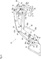
- Parking stand 30 includes a pair of right and left shaft members 30a extended forward from respective right and left masts 11, grounded plates 30b fixed on utmost ends of respective right and left shaft members 30a, and a connection member 30c connecting right and left shaft members 30a to each other.
- Each shaft member 30a is bent at an intermediate portion thereof and is extended downward from the bent intermediate portion thereof so as to be fixedly provided at its lower end with grounded plate 30b.
- Connection member 30c fixedly connects portions of right and left shaft members 30a slightly above grounded plates 30b.
- shaft member 30a is extended rearward from the bent intermediate portion thereof so as to be fixed at its rear end to a portion of each mast 11 slightly below pivot shaft 32. Therefore, when right and left masts 11 rotate relative to respective loader mounts 7, parking stand 30 rotates integrally with right and left masts 11.
- Loader attachment system 20 including each of right and left loader mounts 7 fixed to tractor 1 and each of right and left masts 11 of front end loader 10 will now be described with reference to Figs. 1 to 16B .
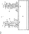
- Loader mount 7 is a vertical plate extended fore-and-aft and vertical directions of tractor 1.
- a rear end edge 7a, a bottom edge 7b, a lower front end edge 7c, a hook portion 7d, a recess 7e, an upper front end edge 7f, a top edge 7g, and an upper rear end edge 7h define the contour of loader mount 7 in side view, as shown in Figs. 10 and 11 .
- Rear end edge 7a is extended vertically.
- Bottom edge 7b is extended arcuately forward from a lower end of rear end edge 7a so as to surround a lower half portion of an outer peripheral edge of support shaft 8.
- Lower front end edge 7c is extended forwardly upward slantwise from a front end of bottom edge 7b.
- Hook portion 7d is formed on a front upper end of lower front end edge 7c so as to extend upward.
- Recess 7e is formed in a U-shape when viewed in side rearwardly downward from hook portion 7d.
- Upper front end edge 7f is extended rearwardly upward from a bottom end of U-shaped recess 7d.
- Top edge 7g is extended horizontally rearward from a rear upper end of upper front end edge 7f.
- Upper rear end edge 7h is extended rearwardly downward slantwise from a rear end of top edge 7g to an upper end of rear end edge 7a.
- a receptacle 7e is formed of a lower-half sleeve-shaped member extended rightward and leftward so as to serve as recess 7e.
- a locking tooth member 21 is fixed onto an angled portion of loader mount 7 serving as a joint between upper front end edge 7f and top edge 7g.
- Locking tooth member 21 is a plate bent in a reverse U-shape when viewed in front so as to form right and left vertical plate portions 21a.
- Right and left vertical plate portions 21a are fixedly stuck to respective right and left side surfaces of loader mount 7 by welding or so on.
- a front upper end portion of locking tooth member 21 is formed as the reverse U-shaped bent portion of loader tooth member 21 so as to serve as a tooth 21b.
- a tooth groove 21c which is U-shaped when viewed in side, is formed on locking tooth member 21 rearward from tooth 21b.
- locking tooth member 21 is formed with an upwardly projecting stopper portion 21d rearward from tooth 21b.
- At least one of right and left vertical plate portions 21a of each locking tooth plate 21 is formed with a guide pin 22 projecting laterally.
- Each mast 11 includes a pair of right and left side plates 23 and a connection plate member 24 interposed between right and left side plates 23.
- a rear end edge 23a, a lower slant edge 23b, a lower front end edge 23c, an upper slant edge 23d, and a top edge 23e define the contour of each side plate 23 when viewed in side.
- Rear end edge 23b is extended vertically (when mast 11 is completely attached to loader mount 7).
- Lower slant edge 23b is extended forwardly downward slantwise from a lower end of rear end edge 23a.
- Lower front end edge 23c is extended upward from a front end of lower slant edge 23b substantially parallel to rear end edge 23a.
- Upper slant edge 23d is extended rearwardly upward slantwise from an upper end of lower front end edge 23c.
- top edge 23e is extended horizontally rearward from an upper end of upper slant edge 23d.
- Side plate 23 of mast 11 is formed with an arcuate guide groove 23f extended forwardly upward from an upper portion of lower slant edge 23b close to the upper end of lower slant edge 23b.
- Guide pin 22 of loader mount 7 is able to enter guide groove 23f.
- Arcuate guide groove 23f defines a part of a circle centered on an axis of a pivot shaft 25 provided on mast 11 as discussed later.
- Arcuate guide groove 23f is extended along a locus of guide pin 22 of loader mount 7 during the rotation of mast 11 centered on the axis of pivot shaft 25 fitted in the recess of receptacle 7e of loader mount 7 relative to loader mount 7.
- Each loader mount 7 and mast 11 may have guide pin 22 and guide groove 23f on each of right and left sides thereof, or on only one of the right and left sides thereof.
- receptacle 7e of loader mount 7 and pivot shaft 25 of mast 11 constitute a support device 20x of loader attachment system 20 configured so as to support mast 11 on loader mount 7 rotatably relative to loader mount 7.
- Guide pin 22 serving as a projection of loader mount 7 and guide groove 23f of mast 11 constitute a location device 20y of loader attachment system 20 so as to enable guide pin 22 to move in guide groove 23f according to the rotation of mast 11 centered on the axis of pivot shaft 25 relative to loader mount 7.
- Connection plate member 24 of mast 11 is formed with an upper rear plate portion 24a, an upper intermediate plate portion 24b, an upper front plate portion 24c, a slant plate portion 24d, and a lower plate portion 24e.
- Upper rear plate portion 24a is extended along rear end edges 23a of side plates 23 from the upper ends of rear end edges 23a of side plates 23 to portions of rear end edges 23a of side plates 23 slightly higher than the lower ends of rear end edges 23a.
- Upper intermediate plate portion 24b is extended slightly downwardly forward from a portion of upper rear plate portion 24a slightly lower than the upper end of upper rear plate portion 24a to portions of upper slant edges 23d of side plates 23 slightly lower than the upper ends of upper slant edges 24d.
- Upper front plate portion 24c is extended along upper slant edges 23d of side plates 23 forwardly downward from a front end of upper intermediate plate portion 24b.
- Slant plate portion 24d is extended rearwardly downward slantwise from a lower end of upper front plate portion 24c.
- Lower plate portion 24e is extended downward from a lower end of slant plate portion 24d.
- Connection plate member 24 is further formed with a lower intermediate plate portion 24f and a slant plate portion 24g.
- Lower intermediate plate portion 24f is extended forward from upper rear plate portion 24a below upper intermediate plate portion 24b.
- Slant plate portion 24g is extended forwardly downward slantwise from a front end of lower intermediate plate portion 24f to a lower end of upper front plate portion 24c.
- Connection plate member 24 interposed between right and left side plates 23 ensures a space between right and left side plates 23 for arranging component members of loader attachment system 20, e.g., a later-discussed locking pawl member 27, and prevents earth and sand from entering the space between right and left side plates 23, thereby protecting the component members in the space between side plates 23.
- a lower end of lower slant edge 23b and a lower end of lower front end edge 23c are joined to each other at a lower end corner portion of each side plate 23.
- Mast 11 is fixedly provided with laterally horizontal pivot shaft 25 between the lower end corner portions of right and left side plates 23.
- a lower end of lower plate portion 24e of connection plate member 24 is disposed immediately above pivot shaft 25.
- Pivot shaft 25 is able to fit to receptacle 7e of loader mount 7.
- Lower plate portion 24e of connection plate member 24 extended upward from pivot shaft 25 is able to be disposed along upper front end edge 7f of loader mount 7 while pivot shaft 25 is fitted to receptacle 7e.
- Mast 11 is provided with laterally horizontal pivot shaft 32 interposed between the front end corner portions of right and left side plates 23 so as to have the tip (rear end) portion of piston rod 17a of arm cylinder 17 fitted on pivot shaft 32.
- Connection plate member 24 has a joint between an upper end of lower plate portion 24e and a lower end of slant plate portion 24d. This joint is disposed immediately rearward from pivot shaft 32.
- Connection plate member 24 also has a joint between an upper end of slant plate portion 24d and a lower end of upper front plate portion 24c. This joint is disposed slightly higher than pivot shaft 31.
- a lower end portion of upper front plate portion 24c and slant plate portion 24d are able to be disposed along tooth 21b of locking tooth member 21 when mast 11 is properly attached to loader mount 7.
- Mast 11 is provided with laterally horizontal pivot shaft 31 interposed between the upper end corner portions of right and left side plates 23 so as to have the rear end portion of rear arm member 61 fitted on pivot shaft 31.
- Upper intermediate plate portion 24b is disposed below the rear end portion of rear arm member 61 pivoted on pivot shaft 31 so as to restrict a lower rotation degree of rear arm member 61, i.e., arm 12, relative to mast 11.
- Lower intermediate plate portion 24f and slant plate portion 24g are spaced from the axis of pivot shaft 26 so as to avoid their interference pawl 27a as the tip portion of locking pawl member 27 during rotation of locking pawl member 27 centered on the axis of pivot shaft 26.
- connection plate portion 24g of connection plate member 24 is disposed forwardly upward from pivot shaft 26 and has a distance from the axis of pivot shaft 26 so as to avoid its interference with pawl 27a of locking pawl member 27 rotating centered on the axis of pivot shaft 26.
- lower intermediate plate portion 24f of connection plate member 24 is disposed above pivot shaft 26 and has a distance from pivot shaft 26 so as to abut against pawl 27a of locking pawl member 27 rotating rearwardly upward.
- lower intermediate plate portion 24f defines a rearward rotation limit position of pawl 27a. Referring to Figs. 14A and 15A , a position of locking pawl member 27 having pawl 27a abutting against lower intermediate plate portion 24f is defined as a later-discussed unlocking position 27U of locking pawl member 27.
- pivot shaft 26 projects outward from distal side plate 23 of laterally proximal and distal side plates 23 of each mast 11.
- a release handle 29 is fixed on the projecting end of pivot shaft 26 and is extended along distal side plate 23.
- An operator operates release handle 29 with his/her hand so as to rotate release handle 29 forward or rearward, whereby pivot shaft 26 rotates centered on its own axis integrally with release handle 29.
- Distal side plate 23 is formed with a handle groove 23g extended forwardly upward slantwise from the projecting outer end portion of pivot shaft 26.
- Handle groove 23g defines a limit position for the forward rotation of release handle 29.
- a position of release handle 29 fitted in handle groove 23g is defined as a lock position 29L of release handle 29, as shown in Fig. 16A and others.
- an edge portion of side plate 23 defining handle groove 23g may be elastic, so that release handle 29 cannot be inserted into handle groove 23g unless release handle 29 is pressed against the edge portion of side plate 23 to expand handle groove 23g. Therefore, side plate 23 of mast 11 may have a force to hold release handle 29 at locking position 29L.
- a pair of torsion spring 28 are interposed between locking pawl member 27 and respective side plates 23. Torsion spring 28 may be interposed between locking pawl member 27 and at least one side plate 23.
- torsion springs 28 bias locking pawl member 27 in a direction to rotate locking pawl member 27 counterclockwise in the left side view. If mast 11 is completely mounted on loader mount 7, a tip end of pawl 27a contacts a rear edge of tooth 21b of locking tooth member 21, and torsion spring 28 biases pawl 27a in a direction to slide pawl 27a rearwardly downward along the rear edge of tooth 21b. This biasing force presses a lower portion of locking pawl member 27 against stopper portion 21d of a top end of locking tooth member 21. This position of locking pawl member 27 in this state is defined as a lock position 27L of locking pawl member 27.
- locking pawl member 27 is located at lock position 27L, where pawl 27a of locking pawl member 27 is fitted into tooth groove 21c of locking tooth member 21 so that locking pawl member 27 and locking tooth member 21 become unrotatable relative to each other.
- torsion springs 28 bias pawl 27a rearwardly downward so as to prevent pawl 27a from moving forwardly upward in a direction of releasing pawl 27a from tooth groove 21c, locking pawl member 27 and locking tooth member 21 are locked to each other so that mast 11 is locked to loader mount 7 on which mast 11 is mounted.
- This biasing direction coincides to the direction of the manipulation force applied to release handle 29 to rotate release handle 29 rearward. Therefore, once spring 29 performs the overcenter action, the manipulation force required for rotating release handle 29 is suddenly lightened. In other words, once release handle 29 rotates rearward to reach the position where torsion springs 28 perform the overcenter action, locking pawl member 27 rotates in the unlocking direction due to only the biasing force of torsion springs 28 instead of the manipulation force applied onto release handle 29, so that locking pawl member 27 finally reaches unlocking position 27U defined by lower intermediate plate portion 24f of connection plate member 24 as mentioned above.
- the setting of position for the overcenter action of torsion springs 28 determines how far locking pawl member 27 should be moved in the unlocking direction by the manipulation force applied onto release handle 29. If the releasing of locking pawl member 27 from locking tooth member 21 is desired to rely on only the manipulation force, the position for overcenter action of springs 28 should be set so that the overcenter action occurs after pawl 27a is completely removed from tooth groove 21c.
- unlocking position 27U defined by lower intermediate plate portion 24f as mentioned above.
- Unlocking position 29U is not a place that manipulated release handle 29 should reach to release locking pawl member 27 from locking tooth member 21 but is a place that release handle 29 naturally reaches when locking pawl member 27 followed by release handle 29 reaches unlocking position 27U.
- locking tooth member 21 of loader mount 7 with tooth 21b, locking pawl member 27 of mast 11 with pawl 27a, overcenter torsion springs 28 interposed between mast 11 and locking pawl member 27, and release handle 29 fixed on pivot shaft 26 serving as the fulcrum for rotation of locking pawl member 27 constitute an engagement device 20x of loader attachment system 20 for locking mast 11 to loader mount 7 when locking mast 11 is completely mounted on loader mount 7.
- At least distal side plate 23 of proximal and distal side plates 23 of mast 11 is made of a transparent or semitransparent member so that locking pawl member 27 disposed inside of mast 11 between proximal and distal side plates 23 is visible from the distal outside of mast 11. Therefore, a person who stands on the laterally distal side of mast 11 to manipulate release handle 29 can see the inside of mast 11 through transparent or semitransparent distal side plate 23 so as to confirm whether locking pawl member 27 in mast 11 is disposed at locking position 27L or unlocking position 27U.
- front end loader 10 is placed so as to have bucket 16 and parking stand 30 (i.e., grounded plates 30b) placed on the ground by their gravity, as shown in Fig. 12B .
- mast 11 is rather slanted forwardly upward.
- Tractor 1 approaches placed front end loader 10 so that masts 11 approach respective loader mounts 7.
- At least right and left arm cylinders 17 of right and left cylinders 17 and 18 are fluidly connected to tractor 1 via hydraulic fluid pipes for operating the telescopic action of piston rods 17a.
- tractor 1 In the condition that loader mount 7 are disposed adjacently rearward of respective masts 11, tractor 1 is stationary. An operator seated in cabin 4 operates to extend piston rods 17a of arm cylinders 17, for instance, to move the lower end portions of masts 11 rearward, whereby pivots 25 get over hook portions 7d, and then are fitted into the arcuate recesses defined by respective receptacles 7e disposed rearward from respective hook portions 7d.
- a state of each loader attachment system 20 where pivot shaft 25 starts fitting to receptacle 7e is defined as a first staged state 20A of loader attachment system 20.
- a rotational position of each mast 11 relative to loader mount 7 is defined as a first rotational position 11A.
- each mast 11 of front end loader 10 is extended forwardly upward slantwise.
- Locking pawl members 27 and release handles 29 may be previously set at unlocking positions 27U and 29U before each of loader attachment systems 20 is set in first staged state 20A as shown in Figs. 12A and 12B .
- this embodiment will be described on an assumption that locking pawl member 27 and release handle 29 are set at locking positions 27L and 29L while loader attachment system 20 transfers from first staged state 20A as shown in Figs. 12A and 12B to a second staged state 20B as shown in Figs. 13A and 13B .
- First staged state 20A of loader attachment system 20 shown in Figs. 12A and 12B means a state where pivot shaft 25 of each mast 11 and receptacle 7e of each loader mount 7 start fitting each other so that support device 20x of loader attachment system 20 starts its function.
- bucket 16 while being grounded by its gravity, slides rearward on the ground so that right and left masts 11 rotate rearward relative to respective loader mounts 7 so as to reduce an angle between each arm 12 and each mast 11.
- each pivot shaft 25 rotates centered on its own axis, and each receptacle 7e allows pivot shaft 25 to slidably rotate thereon.
- support device 20x functions to rotate mast 11 relative to loader mount 7. In this way, each mast 11 rotates centered on the axis of pivot shaft 25 clockwise in the left side view, whereby parking stand 30 is raised so that grounded plates 30b rise apart from the ground.
- each loader attachment system 20 transfers to second staged state 20B as shown in Figs. 13A and 13B .
- mast 11 reaches a second rotational position 11B of mast 11 relative to loader mount 7, where an inlet of guide groove 23f of mast 11 is disposed adjacent to guide pin 22.
- locking pawl member 27 at locking position 27L abuts against a front end of tooth 21b of locking tooth member 21. Therefore, mast 11 cannot rotate rearward relative to loader mount 7 further from second rotational position 11B unless locking pawl member 27 is shifted to unlocking position 27U.
- second staged state 20B of loader attachment system 20 is defined to make the operator notice that release handles 29 should be rotated from respective locking positions 29L. Also, since mast 11 at second rotational position 11B has the inlet of guide groove 23f adjacent to guide pin 22, second staged state 20B of loader attachment system 20 is defined to interrupt the rotation of mast 11 so as to give the operator a time for confirming if mast 11 is ready for sure entrance of guide pin 22 into guide groove 23f, i.e., if loader attachment system 20 is prepared for its next stage in the attachment process where location device 20y can start its proper function.
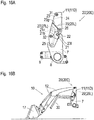
- mast 11 rotating rearward relative to loader mount 7 by contracting piston rod 17a reaches a fourth rotational position 11D as shown in Figs. 15A and 15B , where guide pin 22 reaches the deep end of guide groove 23f so that guide pin 22 cannot move further in guide groove 23f, i.e., mast 11 cannot rotate further rearward relative to loader mount 7. Therefore, the operator notices that piston rods 17a cannot be further contracted, thereby noticing that masts 11 reach respective proper mounting positions on loader mounts 7.
- fourth rotational position 11D is the proper mounting position of mast 11 on loader mount 7. Therefore, the arrival of mast 11 at fourth rotational position 11D means that location device 20y finishes its function to locate mast 11 at the proper mounting position on loader mount 7.
- mast 11 located at fourth rotational position 11D as the proper mounting position is illustrated as having rear end edges 23a of side plates 23 and upper rear plate portion 24a of connection plate member 24 approximately arranged on a vertical plane defined by rear end edge 7a of loader mount 7 (see Figs. 10 and 11 ).
- this is an exemplificative attitude of mast 11 at the proper mounting position.
- Mast 11 at the proper mounting position may have any attitude.
- FIGs. 15A and 15B illustrate such a state of loader attachment system 20 as a fourth staged state 20D of loader attachment system 20.
- torsion springs 28 performs the overcenter action on the way of forward rotation of corresponding release handle 29, so that locking pawl member 27 having been biased toward unlocking position 27U comes to be biased toward locking position 27L.
- tooth groove 21c of locking tooth member 21 of loader mount 7 is just disposed on a locus of pawl 27a of locking pawl member 27 rotating counterclockwise in the left side view, whereby pawl 27a is fitted into tooth groove 21c by shifting release handle 29 to locking position 29L.
- Stopper portion 21d abuts against locking pawl member 27 so as to prevent locking pawl member 27 from further rotating by the biasing force of springs 28, thereby locating locking pawl member 27 at locking position 27L, where locking pawl member 27 engages with locking tooth member 21. Therefore, the engagement of locking pawl member 27 with locking tooth member 21 means that engagement device 20z finishes its locking function to lock mast 11 to loader mount 7.
- Figs. 16A and 16B illustrate a fifth staged state 20E of loader attachment system 20, where release handle 29 is set at locking position 29L so as to place locking pawl member 27 at locking position 27L to engage with locking tooth member 21 while mast 11 is disposed at fourth rotational position 11D.
- Fifth staged state 20E of loader attachment system 20 means that front end loader 10 is completely attached to tractor 1. Afterward, the operator in cabin 4 can operate to telescopically move piston rods 17a of arm cylinders 17 and/or piston rods 18a of bucket cylinders 18 so as to optionally change the position or attitude of bucket 16.
- locking pawl members 27 and release handles 29 are previously set at locking positions 27L and 29L so that the stopping of contraction of piston rods 17a, i.e., the stopping of rotation of masts 11, makes the operator notice that the state of each loader attachment system 20 becomes second staged state 20B where the inlet of guide groove 23f comes close to guide pin 22.
- locking pawl members 27 and release handles 29 may be previously set at unlocking positions 27U and 29U.
- each mast 11 can be rotated without interruption from first rotational position 11A, where pivot shaft 25 starts fitting to receptacle 7e, to fourth rotational position 11D, where guide pin 22 abuts against the deep end of guide groove 23f. Therefore, release handles 29 does not have to be manipulated on the way of the attachment process so as to rotate release handles 29 from locking positions 29L to unlocking positions 29U.
- this case may depend on a condition that guide pin 22 surely enters guide groove 23f without deviation from guide groove 23f even if the rotation of mast 11 is not stopped immediately before guide pin 22 enters guide groove 23f.
- a detachment process to detach each mast 11 from each loader mount 7 is performed by transference of loader attachment system 20 from fifth staged state 20E as the complete attachment state of front end loader 10 to tractor 1 to first staged state 20A, which is a reverse course of the attachment process.
- bucket 16 of front end loader 10 is grounded, and then, release handles 29 are shifted to unlocking positions 29U so as to shift locking pawl member 27 to unlocking position 27U to disengage from locking tooth member 21, thereby setting each loader attachment system 20 at fourth staged state 20D.
- piston rods 17a of arm cylinders 17 are extended so as to rotate each mast 11 forward relative to loader mount 7 from fourth rotational position 11D to first rotational position 11A.
- loader attachment system 20 is adapted for attaching front end loader 10 to tractor 1.
- loader attachment system 20 is adaptable for attaching a backhoe serving as a loader to a vehicle, e.g., a tractor.
Landscapes
- Engineering & Computer Science (AREA)
- Mechanical Engineering (AREA)
- Mining & Mineral Resources (AREA)
- Civil Engineering (AREA)
- General Engineering & Computer Science (AREA)
- Structural Engineering (AREA)
- Agricultural Machines (AREA)
- Shovels (AREA)
Applications Claiming Priority (1)
| Application Number | Priority Date | Filing Date | Title |
|---|---|---|---|
| US15/054,646 US10358789B2 (en) | 2016-02-26 | 2016-02-26 | Loader attachment system |
Publications (2)
| Publication Number | Publication Date |
|---|---|
| EP3211142A2 true EP3211142A2 (fr) | 2017-08-30 |
| EP3211142A3 EP3211142A3 (fr) | 2017-11-29 |
Family
ID=58108531
Family Applications (1)
| Application Number | Title | Priority Date | Filing Date |
|---|---|---|---|
| EP17157410.6A Withdrawn EP3211142A3 (fr) | 2016-02-26 | 2017-02-22 | Système de fixation de chargeur |
Country Status (2)
| Country | Link |
|---|---|
| US (1) | US10358789B2 (fr) |
| EP (1) | EP3211142A3 (fr) |
Cited By (2)
| Publication number | Priority date | Publication date | Assignee | Title |
|---|---|---|---|---|
| EP3708717A1 (fr) * | 2019-03-14 | 2020-09-16 | Kubota Corporation | Chargeur et machine de travail |
| US11143086B2 (en) | 2018-04-20 | 2021-10-12 | Wacker Neuson Linz Gmbh | Working vehicle having an outlet-side cooling-air deflection installation |
Families Citing this family (5)
| Publication number | Priority date | Publication date | Assignee | Title |
|---|---|---|---|---|
| US10753063B2 (en) | 2017-12-27 | 2020-08-25 | Kubota Corporation | Front loader |
| US10036138B1 (en) * | 2017-12-27 | 2018-07-31 | Kubota Corporation | Front loader and working machine with left and right wires |
| US10119242B1 (en) * | 2018-03-27 | 2018-11-06 | Deere & Company | Front loader mounting arrangement for a work vehicle |
| US12398529B2 (en) * | 2022-10-20 | 2025-08-26 | Deere & Company | Loader latching assist method and apparatus |
| US12043978B1 (en) | 2023-07-19 | 2024-07-23 | William R. Leinert | Bucket lifting extension device |
Citations (1)
| Publication number | Priority date | Publication date | Assignee | Title |
|---|---|---|---|---|
| US20060245899A1 (en) | 2005-05-02 | 2006-11-02 | Deere & Company, A Delaware Corporation | Latching system for automatically securing front-mounted loader mast to tractor-carried loader mounting frame |
Family Cites Families (6)
| Publication number | Priority date | Publication date | Assignee | Title |
|---|---|---|---|---|
| US4264264A (en) | 1979-02-26 | 1981-04-28 | Deere & Company | Loader mounting structure |
| JPS5943560U (ja) | 1982-09-13 | 1984-03-22 | 高北農機株式会社 | フロントロ−ダ−の着脱装置 |
| DE3517151A1 (de) | 1985-05-11 | 1986-11-13 | Xaver Fendt & Co, 8952 Marktoberdorf | Verfahren zum abbauen eines auf stuetzen abstellbaren frontladers von einem ladefahrzeug mit unterschiedlicher wirksamer hoehe, insbesondere land- und/oder bauwirtschaftlich nutzbaren schlepper, sowie frontlader zur durchfuehrung des verfahrens |
| JPH0730767Y2 (ja) | 1989-02-15 | 1995-07-19 | 株式会社クボタ | フロントローダのマスト取付装置 |
| US5620297A (en) | 1996-02-14 | 1997-04-15 | Mahaney; F. Allen | Tractor loader mounting structure |
| DE102013222165A1 (de) * | 2013-10-01 | 2015-04-02 | Deere & Company | Frontladeranordnung |
-
2016
- 2016-02-26 US US15/054,646 patent/US10358789B2/en not_active Expired - Fee Related
-
2017
- 2017-02-22 EP EP17157410.6A patent/EP3211142A3/fr not_active Withdrawn
Patent Citations (1)
| Publication number | Priority date | Publication date | Assignee | Title |
|---|---|---|---|---|
| US20060245899A1 (en) | 2005-05-02 | 2006-11-02 | Deere & Company, A Delaware Corporation | Latching system for automatically securing front-mounted loader mast to tractor-carried loader mounting frame |
Cited By (5)
| Publication number | Priority date | Publication date | Assignee | Title |
|---|---|---|---|---|
| US11143086B2 (en) | 2018-04-20 | 2021-10-12 | Wacker Neuson Linz Gmbh | Working vehicle having an outlet-side cooling-air deflection installation |
| EP3708717A1 (fr) * | 2019-03-14 | 2020-09-16 | Kubota Corporation | Chargeur et machine de travail |
| JP2020148082A (ja) * | 2019-03-14 | 2020-09-17 | 株式会社クボタ | フロントローダ及び作業機 |
| US10851518B2 (en) | 2019-03-14 | 2020-12-01 | Kubota Corporation | Front loader and work machine |
| US11168461B2 (en) | 2019-03-14 | 2021-11-09 | Kubota Corporation | Front loader and work machine |
Also Published As
| Publication number | Publication date |
|---|---|
| US20170247854A1 (en) | 2017-08-31 |
| EP3211142A3 (fr) | 2017-11-29 |
| US10358789B2 (en) | 2019-07-23 |
Similar Documents
| Publication | Publication Date | Title |
|---|---|---|
| EP3211142A2 (fr) | Système de fixation de chargeur | |
| US7168907B2 (en) | Latching system for automatically securing front-mounted loader mast to tractor-carried loader mounting frame | |
| CN107075835B (zh) | 作业车辆 | |
| US5540289A (en) | Stand apparatus for use in coupling and uncoupling a front loader | |
| EP2682530B1 (fr) | Chargeur sur roues | |
| CN109972681B (zh) | 前装载机 | |
| US8651220B2 (en) | Multi-directionally adjustable control pods | |
| CA2579106A1 (fr) | Robot avec arret de fleche | |
| EP2310578B1 (fr) | Dispositif de verrouillage destiné à fixer une pelle rétrocaveuse à un bras de levage porteur | |
| JP2017106180A (ja) | 作業車及びフロントローダ | |
| US6332748B1 (en) | Rotating pawl tool latch | |
| EP3249107B1 (fr) | Véhicule de travail et chargeur avant | |
| US10145082B2 (en) | Work vehicle and backhoe | |
| JP2008196275A (ja) | アタッチメント連結装置および作業機械 | |
| JP6523935B2 (ja) | フロントローダ及び作業車 | |
| JPH0480434A (ja) | ローダ車輌の油圧継手装置 | |
| CA3012329C (fr) | Transmissions de commande mecanique | |
| JP6804590B2 (ja) | 作業車及びフロントローダ | |
| JP3693794B2 (ja) | 乗用管理作業車の作業機装着装置 | |
| JPH0344828Y2 (fr) | ||
| JPH0621286Y2 (ja) | クイックヒッチ装置 | |
| JP2537684B2 (ja) | トラクタにおける作業機着脱装置 | |
| JP4789779B2 (ja) | フロントローダ | |
| JPH07255211A (ja) | 作業機装着装置 | |
| JP2005178412A (ja) | 乗用田植機 |
Legal Events
| Date | Code | Title | Description |
|---|---|---|---|
| PUAI | Public reference made under article 153(3) epc to a published international application that has entered the european phase |
Free format text: ORIGINAL CODE: 0009012 |
|
| AK | Designated contracting states |
Kind code of ref document: A2 Designated state(s): AL AT BE BG CH CY CZ DE DK EE ES FI FR GB GR HR HU IE IS IT LI LT LU LV MC MK MT NL NO PL PT RO RS SE SI SK SM TR |
|
| AX | Request for extension of the european patent |
Extension state: BA ME |
|
| PUAL | Search report despatched |
Free format text: ORIGINAL CODE: 0009013 |
|
| AK | Designated contracting states |
Kind code of ref document: A3 Designated state(s): AL AT BE BG CH CY CZ DE DK EE ES FI FR GB GR HR HU IE IS IT LI LT LU LV MC MK MT NL NO PL PT RO RS SE SI SK SM TR |
|
| AX | Request for extension of the european patent |
Extension state: BA ME |
|
| RIC1 | Information provided on ipc code assigned before grant |
Ipc: E02F 3/36 20060101AFI20171020BHEP Ipc: E02F 3/627 20060101ALI20171020BHEP |
|
| STAA | Information on the status of an ep patent application or granted ep patent |
Free format text: STATUS: THE APPLICATION IS DEEMED TO BE WITHDRAWN |
|
| 18D | Application deemed to be withdrawn |
Effective date: 20180530 |