EP3211169B1 - Schieberrahmen mit sperrelement für ein transversales element - Google Patents
Schieberrahmen mit sperrelement für ein transversales element Download PDFInfo
- Publication number
- EP3211169B1 EP3211169B1 EP17156724.1A EP17156724A EP3211169B1 EP 3211169 B1 EP3211169 B1 EP 3211169B1 EP 17156724 A EP17156724 A EP 17156724A EP 3211169 B1 EP3211169 B1 EP 3211169B1
- Authority
- EP
- European Patent Office
- Prior art keywords
- transversal
- upright
- sash
- locking
- cavity
- Prior art date
- Legal status (The legal status is an assumption and is not a legal conclusion. Google has not performed a legal analysis and makes no representation as to the accuracy of the status listed.)
- Active
Links
Images




Classifications
-
- E—FIXED CONSTRUCTIONS
- E06—DOORS, WINDOWS, SHUTTERS, OR ROLLER BLINDS IN GENERAL; LADDERS
- E06B—FIXED OR MOVABLE CLOSURES FOR OPENINGS IN BUILDINGS, VEHICLES, FENCES OR LIKE ENCLOSURES IN GENERAL, e.g. DOORS, WINDOWS, BLINDS, GATES
- E06B3/00—Window sashes, door leaves, or like elements for closing wall or like openings; Layout of fixed or moving closures, e.g. windows in wall or like openings; Features of rigidly-mounted outer frames relating to the mounting of wing frames
- E06B3/96—Corner joints or edge joints for windows, doors, or the like frames or wings
- E06B3/964—Corner joints or edge joints for windows, doors, or the like frames or wings using separate connection pieces, e.g. T-connection pieces
- E06B3/968—Corner joints or edge joints for windows, doors, or the like frames or wings using separate connection pieces, e.g. T-connection pieces characterised by the way the connecting pieces are fixed in or on the frame members
- E06B3/9684—Corner joints or edge joints for windows, doors, or the like frames or wings using separate connection pieces, e.g. T-connection pieces characterised by the way the connecting pieces are fixed in or on the frame members by hooking protrusions on the connecting piece in openings of the frame member, e.g. by snap-locking
-
- E—FIXED CONSTRUCTIONS
- E06—DOORS, WINDOWS, SHUTTERS, OR ROLLER BLINDS IN GENERAL; LADDERS
- E06B—FIXED OR MOVABLE CLOSURES FOR OPENINGS IN BUILDINGS, VEHICLES, FENCES OR LIKE ENCLOSURES IN GENERAL, e.g. DOORS, WINDOWS, BLINDS, GATES
- E06B3/00—Window sashes, door leaves, or like elements for closing wall or like openings; Layout of fixed or moving closures, e.g. windows in wall or like openings; Features of rigidly-mounted outer frames relating to the mounting of wing frames
- E06B3/30—Coverings, e.g. protecting against weather, for decorative purposes
- E06B3/301—Coverings, e.g. protecting against weather, for decorative purposes consisting of prefabricated profiled members or glass
- E06B3/302—Covering wooden frames with metal or plastic profiled members
-
- E—FIXED CONSTRUCTIONS
- E06—DOORS, WINDOWS, SHUTTERS, OR ROLLER BLINDS IN GENERAL; LADDERS
- E06B—FIXED OR MOVABLE CLOSURES FOR OPENINGS IN BUILDINGS, VEHICLES, FENCES OR LIKE ENCLOSURES IN GENERAL, e.g. DOORS, WINDOWS, BLINDS, GATES
- E06B3/00—Window sashes, door leaves, or like elements for closing wall or like openings; Layout of fixed or moving closures, e.g. windows in wall or like openings; Features of rigidly-mounted outer frames relating to the mounting of wing frames
- E06B3/68—Window bars
-
- E—FIXED CONSTRUCTIONS
- E06—DOORS, WINDOWS, SHUTTERS, OR ROLLER BLINDS IN GENERAL; LADDERS
- E06B—FIXED OR MOVABLE CLOSURES FOR OPENINGS IN BUILDINGS, VEHICLES, FENCES OR LIKE ENCLOSURES IN GENERAL, e.g. DOORS, WINDOWS, BLINDS, GATES
- E06B3/00—Window sashes, door leaves, or like elements for closing wall or like openings; Layout of fixed or moving closures, e.g. windows in wall or like openings; Features of rigidly-mounted outer frames relating to the mounting of wing frames
- E06B3/96—Corner joints or edge joints for windows, doors, or the like frames or wings
- E06B3/964—Corner joints or edge joints for windows, doors, or the like frames or wings using separate connection pieces, e.g. T-connection pieces
- E06B3/9641—Corner joints or edge joints for windows, doors, or the like frames or wings using separate connection pieces, e.g. T-connection pieces part of which remains visible
Definitions
- the present invention relates to a sash and a method of assembling the sash.
- a sash is usually known as a component adapted to close an architectural opening; in other words, sashes are known to make a division between two rooms otherwise communicating via such as an architectural opening.
- sashes exist, containing multiple parts and multiple portions, for example comprising movable parts, generally rotatable, known as doors, and fixed parts, locked to the sub-frame, known as frame.
- sashes divide the exteriors from the interiors, or divide two interiors.
- the sashes that divide two interiors, or the sashes that divide an interior from an exterior can have different features to respond to different needs, for example according to the conditions present in these environments, i.e. depending on which elements are present or not.
- the sash object of the present invention is particularly suitable for the division of an interior from an exterior but can also be used to divide two interiors.
- the sashes of the present invention are of the type having a wooden part and a part in another material, such as aluminium or PVC.
- the wooden part is facing towards the interior while the aluminium or PVC is facing outwards and is subject to weather conditions.
- the main problem of this type of sashes is to have many difficulties in assembling the various components and in the subsequent installation of the sash, with particular reference to the cover frame.
- the object of the present invention is to provide a sash which minimises and/or resolve such difficulties of assembly and installation.
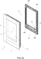
- reference numeral 1 denotes, as a whole, a sash for closing an architectural opening.
- sash 1 has an inner side I, facing an internal environment, and an outer side E, facing an external environment, for example open and therefore subject to weather.
- sash 1 is a window or a French window.
- window and “French window” means in the following description any solution of sash 1 in which there is a moving wing, mounted on a frame, where the window is small in size and lifted from the ground plane, while the French window is larger and extends above the ground plane; preferably, the term window is meant to also include solutions such as skylights or French doors.
- sash 1 has a fixed wing mounted on a frame, or only the frame itself.
- sash 1 object of the present invention as described hereinafter, has embodiments in which it has both movable and fixed portions, and embodiments in which it is totally fixed.
- the sash 1 comprises at least one transparent element 2, preferably of a planar shape, suitable to allow the passage of light, having an inner face 21 and an outer face 22.
- the transparent elements 2 are two.
- the transparent element 2 is a glass plate, or is double glazing, or triple glazing, or a glass block, or a glass block with integrated curtain.
- sash 1 comprises a weight-bearing frame 3 adapted to support the transparent element 2, fixing it by engaging the inner face 21.
- the weight-bearing frame 3 is made of wood.
- the weight-bearing frame 3 is placed towards the inside.
- the sash comprises a cover frame 4 adapted to protect the weight-bearing frame 3.
- the cover frame 4 is placed towards the outside.
- the cover frame 4 is of a suitable material to resist weathering, such as aluminium; there are also embodiments in which said cover frame 4 is made of polymeric material such as PVC.
- sash 1 comprises a plurality of fixing elements 20 attached to weight-bearing frame 3 and supporting the cover frame 4; preferably, the cover frame 4, widely described hereinafter, is suitable to be snap-engaged on said fixing elements 20.
- the fixing body 20 comprises a fixing portion 210 adapted to engage the transparent element 2 to secure it on the weight-bearing frame 3 and a support portion 250 suitable for being snap-engaged by the cover frame 4 to fix it to the weight-bearing frame 3.
- the cover frame 4 comprises a structure 40 comprising upright elements 41 and transversal elements 42 suitable to engage to each other.
- the upright elements 41 and the transversal elements 42 are suitable to mutually arrange so as to lie on the same plane. They are arranged perpendicularly to one another.
- the upright element 41 defines, along its extension, an upright cavity 410'.
- the upright element 41 has a substantially C-shaped or U-shaped section.
- the upright element 41 defines, along its extension, an upright groove 410", in other words, in length, preferably a lateral end, a groove is provided which is typically suitable to contain a seal also suitable to engage the transparent element 2.
- the transversal element 42 also defines, along its extension, a transversal cavity 420.
- the transversal element 42 has a substantially C-shaped or U-shaped section.
- the transversal element 42 also defines a transversal groove 420" extending in length, which is suitable to contain a seal also suitable to engage the transparent element 2.
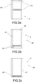
- the upright elements 42 comprise an upper transversal element, and/or an added central transversal element, and/or an added lower transversal element and/or a lower transversal element.
- the upper and lower transversal elements are suitable to join the two upright elements 41 of a structure 40 at the upper and lower ends, while the added elements are placed between said lower and upper transversal elements as shown in figures 2a, 2b and 2c .
- sash 1 object of the present invention comprises a plurality of locking elements 10 adapted to implement the lock between an upright element 41 and a transversal element 42.
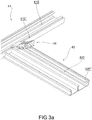
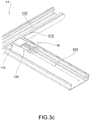
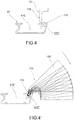
- the locking element 10 comprises an upright portion 110 adapted to be housed in the upright cavity 410' and/or in the upright groove 410"; moreover, the locking element 10 comprises a transversal portion 120 adapted to be snap-engaged in the transversal cavity 420 of the transversal element 42.
- the upright portion 110 and the transversal portion 120 are mutually interacting in such a way that the engagement between the transversal portion 120 and transversal element 42 transmits an action that forcibly locks the upright element 41 to the transversal element 42.
- the transversal portion 120 comprises two locking wings 125, one in front of the other, which extend in length along the transversal portion 120, suitable to snap-engage the walls that delimit the transversal cavity 420.
- the locking wings 125 are elastically yielding 125 in such a way as to allow (by squeezing) access of the transversal portion 120 inside the transversal cavity 420 and allow (by widening) the locking to the transversal element 120.
- each locking wing 125 comprises a plurality of locking teeth 125'.
- the locking teeth 125' part of a locking wing 125 axially mutually side by side are two or three.
- the locking elements 10 are particularly efficient by operating between added upright elements 41 and transversal elements 42.
- the cover frame 4 comprises joint elements 400, preferably L-shaped, suitable to perform the locking between the upright element 41 and the upper transversal element and/or lower transversal element coming to be housed in a portion of the upright cavity 401 and in a portion of the transversal cavity 402 (as shown in some of the accompanying figures).
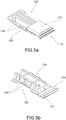
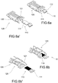
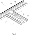
- the locking element 10 consists of a single piece (such as shown in the embodiments in figures 3 , 5 and 7 ).
- the locking element 10 is of a material selected from polymeric alloys, for example it is of fiberglass reinforced nylon.
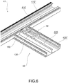
- the upright portion 110 and the transversal portion 120 are two separate components (as is instead shown in the solution in figure 6 ) .
- the upright portion 110 comprises a coupling body 111 and the transversal portion 120 comprises a housing 121 in which the coupling body 111 of the supporting portion 110 is housed.
- the upright portion 110 is made of a material selected from among the metallic alloys
- the transversal portion 120 is made of a material selected from the polymeric alloys, for example it is of fiberglass reinforced nylon.
- the upright portion 110 includes a locking lip 112 that engages the walls of the upright cavity 410' and/or in the upright groove 410" in the action of locking the locking element 10 to the respective upright element 41.
- said locking lip 112 is specially shaped as a hook or spike form to engage the respective wall or portion of the upright element 41 (as shown by way of example in figures 3 , 5 , 6 ).
- the upright portion 110 is suitable for being snap-engaged in the upright cavity 410' of the upright element 41.
- the upright portion 110 has a shape similar to the transversal portion 120.
- Another object of the present invention is also an assembly method of a sash 1, according to embodiments described above.
- Such an assembly method comprises the steps of:
- the upright portion 110 and in particular the locking lip 112 is inserted transversely to the upright portion 410' and the upright groove 410" and during the rotation of the locking element 10, the locking lip 112 starts to cooperate with the walls of the respective housing to ensure the locking between upright element 41 and transversal element 42.
- the described rotation of the locking element 10 performs an angle of substantially 90°.
- the reference to the cited documents by the Applicant makes complete reference to the features of the upright element and of the transversal element, such as their mutual engagement at the corner, or the presence of break-drop elements; or to the features of the fixing element, in particular how it is suitable for fixing the cover frame to the weight-bearing frame and support the transparent element on the latter (in such documents by the Applicant it is called locking element); or additionally to the geometric and operational features of the joint element and how this is suitable to mutually lock transversal element and upright element at the corner.
- the sash object of the present invention achieves the object of the present invention by providing minimised and/or resolved difficulties of assembling and mounting.
- the cover frame is easy to mount and assemble.
- the locking of the transversal element to the upright element using the locking element takes place in a simple and intuitive and error-free manner.
- the locking element is adapted to facilitate any welding work between transversal element and upright element, for example prior to the painting of the cover frame, keeping the transversal element and upright element in a predefined position thereof.
- the locking element is suitable for allowing the locking between upright element and any type of transversal element, for example upper upright element, lower upright element, added central upright element, added lower upright element.
- An advantageous aspect of the locking element in the embodiments in which the upright portion is housed in the upright groove is to not take up space in said upright cavity, in which, therefore, fixing elements are housed for fixing the cover frame to the weight-bearing frame, and/or the joint elements adapted to lock the upright element with the transversal element to the corner.
- the locking element as it is a single element, is easily manufactured, for example through plastic moulding.
- the locking element 10 has the same features described above, except that, unlike what is described above, its upright portion 110 is adapted to be housed in the transversal cavity 420 and/or in the transversal groove 420", while its transversal portion 120 is adapted to be snap-housed in the upright cavity 41 of the respective added upright element 410.
Landscapes
- Engineering & Computer Science (AREA)
- Civil Engineering (AREA)
- Structural Engineering (AREA)
- Wing Frames And Configurations (AREA)
- Securing Of Glass Panes Or The Like (AREA)
Claims (10)
- Fenster- bzw. Schieberahmen (1) zum Verschließen einer architektonischen Öffnung, umfassend:i) einen gewichtstragenden Rahmen (3), der nach innen hin platziert ist, vorzugsweise aus Holz;ii) zumindest ein transparentes Element (2), vorzugsweise von planarer Form, das geeignet ist, den Durchtritt von Licht durch den Fensterrahmen (1) zu erlauben, und das auf dem gewichtstragenden Rahmen (3) untergebracht ist und durch diesen getragen wird;iii) Abdeckungsrahmen (4), der nach außen hin platziert ist, vorzugsweise aus Aluminium, der an den gewichtstragenden Rahmen (3) gepasst ist und dazu geeignet ist, diesen an der Außenseite zu schützen;wobei der Abdeckungsrahmen (4) umfasst:n) eine Struktur (40) mit aufrechten Elementen (41) und transversalen Elementen (42), die dazu geeignet sind, senkrecht ineinanderzugreifen, wobei das aufrechte Element (41) entlang seiner Erstreckung einen aufrechten Hohlraum (410') und/oder eine aufrechte Nut (410") definiert und das transversale Element (42) entlang seiner Erstreckung einen transversalen Hohlraum (420) definiert;m) eine Mehrzahl von Verriegelungselementen (10), wobei jedes Verriegelungselement einstückig hergestellt ist und umfasst:dadurch gekennzeichnet, dass jedes Verriegelungselement ferner umfasst:- einen aufrechten Abschnitt (110) mit einer Verriegelungslippe (112), die geeignet ist, mit einer transversalen Einsetzung in der aufrechten Nut (410") untergebracht zu werden;- einen transversalen Abschnitt (120), der geeignet ist, mit einer Drehung des Verriegelungselements (10) in den transversalen Hohlraum (420) des transversalen Elements (42) einzuschnappen; undwobei der aufrechte Abschnitt (110) und der transversale Abschnitt (120) derart miteinander in Wechselwirkung stehen, dass der Schnappeingriff zwischen dem transversalen Abschnitt (120) und dem transversalen Element (42), der durch die Drehung des Verriegelungselements (10) erreicht wird, eine Aktion auf die Verriegelungslippe (112) überträgt, die in die Wände der aufrechten Nut (410") eingreift, in der das aufrechte Element (41) untergebracht ist und gewaltsam mit dem transversalen Element (42) verriegelt wird.
- Fensterrahmen (1) nach Anspruch 1, wobei die transversalen Elementen (42) ein oberes transversales Element und/oder ein hinzugefügtes zentrales transversalen Element und/oder ein hinzugefügtes unteres transversales Element und/oder ein unteres transversalen Element umfassen, wobei eines der transversalen Elemente (42) mittels eines Verriegelungselements (10) an einem aufrechten Element (41) verriegelt ist.
- Fensterrahmen (1) nach einem der vorhergehenden Ansprüche, wobei das Verriegelungselement (10) aus einem Material hergestellt ist, das aus den Polymerlegierungen, vorzugsweise aus glasfaserverstärktem Nylon ausgewählt ist.
- Fensterrahmen (1) nach einem der vorhergehenden Ansprüche, wobei der transversale Abschnitt (120) zwei Verriegelungsflügel (125) umfasst, einer vor dem anderen, die sich in Länge entlang des transversalen Abschnitts (120) erstrecken und geeignet sind, in die Wände einzuschnappen, die den transversalen Hohlraum (420) begrenzen.
- Fensterrahmen (1) nach Anspruch 4, wobei jeder Verriegelungsflügel (125) eine Mehrzahl von Verriegelungszähnen (125') umfasst.
- Fensterrahmen (1) nach einem der vorhergehenden Ansprüche, umfassend eine Mehrzahl von Befestigungskörpern (20), die an dem gewichtstragenden Rahmen (3) fixierbar bzw. anbringbar sind, wobei ein Befestigungskörper (20) umfasst:i) einen Befestigungsabschnitt (210), der geeignet ist, in das transparente Element (2) einzugreifen, um es an dem gewichtstragenden Rahmen (3) zu befestigen;ii) einen Stütz- bzw. Trägerabschnitt (250), der geeignet ist, durch den Abdeckungsrahmen (4) in Schnappeingriff genommen zu werden, der in dem aufrechten Hohlraum (410') und dem transversalen Hohlraum (420) untergebracht ist, um dessen Befestigung an dem gewichtstragenden Rahmen (3) durchzuführen.
- Fensterrahmen (1) nach Anspruch 6, wobei der Abdeckungsrahmen (4) Gelenkelemente (400) umfasst, die vorzugsweise L-förmig sind und dazu geeignet sind, die Verriegelung zwischen dem aufrechten Element (41) und dem oberen transversalen Element und/oder dem unteren transversalen Element durchzuführen, das bzw. die in einem Abschnitt des aufrechten Hohlraums (401) und in einem Abschnitt des transversalen Hohlraums (402) unterzubringen ist bzw. sind.
- Fensterrahmen (1) nach einem der vorhergehenden Ansprüche, wobei das transparente Element (2) eine Glasplatte oder eine Doppelverglasung oder eine Dreifachverglasung oder ein Glasblock oder ein Glasblock mit integriertem Vorhang ist.
- Fensterrahmen (1) nach einem der vorhergehenden Ansprüche, wobei der Fensterrahmen (1) ein Fenster oder eine Fenstertür bzw. ein französisches Fenster ist.
- Montageverfahren eines Fensterrahmens (1) nach einem der vorhergehenden Ansprüche, umfassend die Schritte:- Positionieren des transversalen Elements (42) auf einer vordefinierten Höhe in Bezug auf das aufrechte Element (41);- Einsetzen des aufrechten Abschnitts (110) des Verriegelungselements (11) in den aufrechten Hohlraum (410') oder in die aufrechte Nut (410");- Drehen des Verriegelungselements (11), wobei der aufrechte Abschnitt (110) in Position gehalten wird, bis der transversale Abschnitt (120) in den jeweiligen transversalen Hohlraum (420) eingesetzt und eingerastet bzw. in Schnappverriegelung ist.
Applications Claiming Priority (1)
| Application Number | Priority Date | Filing Date | Title |
|---|---|---|---|
| ITUB2016A001091A ITUB20161091A1 (it) | 2016-02-26 | 2016-02-26 | Serramento con elemento di bloccaggio per elementi traversa |
Publications (2)
| Publication Number | Publication Date |
|---|---|
| EP3211169A1 EP3211169A1 (de) | 2017-08-30 |
| EP3211169B1 true EP3211169B1 (de) | 2019-12-11 |
Family
ID=56027080
Family Applications (1)
| Application Number | Title | Priority Date | Filing Date |
|---|---|---|---|
| EP17156724.1A Active EP3211169B1 (de) | 2016-02-26 | 2017-02-17 | Schieberrahmen mit sperrelement für ein transversales element |
Country Status (2)
| Country | Link |
|---|---|
| EP (1) | EP3211169B1 (de) |
| IT (1) | ITUB20161091A1 (de) |
Family Cites Families (4)
| Publication number | Priority date | Publication date | Assignee | Title |
|---|---|---|---|---|
| DE2065100C3 (de) * | 1970-11-10 | 1978-03-02 | Alco Bauzubehoer Gmbh & Co, 3380 Goslar | Rahmen für Fenster oder Türen |
| CH674044A5 (en) * | 1987-06-26 | 1990-04-30 | Koller Metallbau Ag | Profiled bar structure for window frame - has recesses in second bar for connector engaging in groove in first |
| AT404053B (de) * | 1996-02-28 | 1998-08-25 | Wick Josef & Soehne | Eckverbindung für profile |
| DE202006004609U1 (de) * | 2006-03-21 | 2006-06-08 | Corus Aluminium Profiltechnik Gmbh | Vorrichtung zur Abdeckung von Holzrahmen |
-
2016
- 2016-02-26 IT ITUB2016A001091A patent/ITUB20161091A1/it unknown
-
2017
- 2017-02-17 EP EP17156724.1A patent/EP3211169B1/de active Active
Non-Patent Citations (1)
| Title |
|---|
| None * |
Also Published As
| Publication number | Publication date |
|---|---|
| EP3211169A1 (de) | 2017-08-30 |
| ITUB20161091A1 (it) | 2017-08-26 |
Similar Documents
| Publication | Publication Date | Title |
|---|---|---|
| US9316040B2 (en) | Field mulling system for windows and doors | |
| CA1135565A (en) | Window replacement system | |
| US10017980B2 (en) | Window mull system | |
| US8640339B2 (en) | Brick moulding system for window frames and door frames and method of manufacture of same | |
| CA2863237C (en) | Manufactures, methods and structures to reduce energy transfer in buildings | |
| KR20240134210A (ko) | 도어 바디 구조 | |
| US20120055637A1 (en) | Transparent security shutter | |
| EP3293338B1 (de) | Schiebeelement mit verschlusselement | |
| CA2218091A1 (en) | Window assembly | |
| KR101303277B1 (ko) | 미닫이 창호의 도어 어셈블리 및 이의 조립 방법 | |
| EP2955310B1 (de) | Zarge mit abdeckrahmen | |
| EP3211169A1 (de) | Schieberrahmen mit sperrelement für ein transversales element | |
| US20200238795A1 (en) | Window assembly having flush frame to sash | |
| GB2416561A (en) | Frame perpendicular joint | |
| EP1989385B1 (de) | Wärmebeständiges fensterrahmenglied und fensteranordnung | |
| CN212054315U (zh) | 外推式采光窗 | |
| US10612293B1 (en) | Storm or secondary window installation system and method of installation | |
| JP2000054740A (ja) | 引違い窓 | |
| KR102018426B1 (ko) | 재단 및 조립이 용이한 입면 분할 창호 | |
| NZ583779A (en) | Window and door frames and sashes lined with insulating thermoplastic layer | |
| EP4279680B1 (de) | Fensterrahmen mit ecken | |
| EP2933419B1 (de) | Fensterprodukte | |
| EP3321464A1 (de) | Rahmen mit gleitflächen aufweisenden verschlusselement | |
| EP1640547A1 (de) | Verfahren zum Befestigen eines Abdeckelements an einem Fensterrahmen und Abdeckelement hierfür | |
| CA2918916C (en) | Mull system for windows and doors |
Legal Events
| Date | Code | Title | Description |
|---|---|---|---|
| PUAI | Public reference made under article 153(3) epc to a published international application that has entered the european phase |
Free format text: ORIGINAL CODE: 0009012 |
|
| STAA | Information on the status of an ep patent application or granted ep patent |
Free format text: STATUS: THE APPLICATION HAS BEEN PUBLISHED |
|
| AK | Designated contracting states |
Kind code of ref document: A1 Designated state(s): AL AT BE BG CH CY CZ DE DK EE ES FI FR GB GR HR HU IE IS IT LI LT LU LV MC MK MT NL NO PL PT RO RS SE SI SK SM TR |
|
| AX | Request for extension of the european patent |
Extension state: BA ME |
|
| STAA | Information on the status of an ep patent application or granted ep patent |
Free format text: STATUS: REQUEST FOR EXAMINATION WAS MADE |
|
| 17P | Request for examination filed |
Effective date: 20171219 |
|
| RAX | Requested extension states of the european patent have changed |
Extension state: ME Extension state: BA Payment date: 20171219 |
|
| RBV | Designated contracting states (corrected) |
Designated state(s): AL AT BE BG CH CY CZ DE DK EE ES FI FR GB GR HR HU IE IS IT LI LT LU LV MC MK MT NL NO PL PT RO RS SE SI SK SM TR |
|
| STAA | Information on the status of an ep patent application or granted ep patent |
Free format text: STATUS: EXAMINATION IS IN PROGRESS |
|
| 17Q | First examination report despatched |
Effective date: 20180910 |
|
| RIC1 | Information provided on ipc code assigned before grant |
Ipc: E06B 3/968 20060101ALI20190509BHEP Ipc: E06B 3/30 20060101AFI20190509BHEP Ipc: E06B 3/68 20060101ALI20190509BHEP Ipc: E06B 3/964 20060101ALN20190509BHEP |
|
| INTG | Intention to grant announced |
Effective date: 20190617 |
|
| RIC1 | Information provided on ipc code assigned before grant |
Ipc: E06B 3/30 20060101AFI20190603BHEP Ipc: E06B 3/968 20060101ALI20190603BHEP Ipc: E06B 3/964 20060101ALN20190603BHEP Ipc: E06B 3/68 20060101ALI20190603BHEP |
|
| GRAS | Grant fee paid |
Free format text: ORIGINAL CODE: EPIDOSNIGR3 |
|
| STAA | Information on the status of an ep patent application or granted ep patent |
Free format text: STATUS: GRANT OF PATENT IS INTENDED |
|
| GRAJ | Information related to disapproval of communication of intention to grant by the applicant or resumption of examination proceedings by the epo deleted |
Free format text: ORIGINAL CODE: EPIDOSDIGR1 |
|
| GRAL | Information related to payment of fee for publishing/printing deleted |
Free format text: ORIGINAL CODE: EPIDOSDIGR3 |
|
| STAA | Information on the status of an ep patent application or granted ep patent |
Free format text: STATUS: EXAMINATION IS IN PROGRESS |
|
| GRAP | Despatch of communication of intention to grant a patent |
Free format text: ORIGINAL CODE: EPIDOSNIGR1 |
|
| STAA | Information on the status of an ep patent application or granted ep patent |
Free format text: STATUS: GRANT OF PATENT IS INTENDED |
|
| INTC | Intention to grant announced (deleted) | ||
| RIC1 | Information provided on ipc code assigned before grant |
Ipc: E06B 3/30 20060101AFI20190923BHEP Ipc: E06B 3/964 20060101ALN20190923BHEP Ipc: E06B 3/968 20060101ALI20190923BHEP Ipc: E06B 3/68 20060101ALI20190923BHEP |
|
| INTG | Intention to grant announced |
Effective date: 20191009 |
|
| GRAA | (expected) grant |
Free format text: ORIGINAL CODE: 0009210 |
|
| STAA | Information on the status of an ep patent application or granted ep patent |
Free format text: STATUS: THE PATENT HAS BEEN GRANTED |
|
| AK | Designated contracting states |
Kind code of ref document: B1 Designated state(s): AL AT BE BG CH CY CZ DE DK EE ES FI FR GB GR HR HU IE IS IT LI LT LU LV MC MK MT NL NO PL PT RO RS SE SI SK SM TR |
|
| AX | Request for extension of the european patent |
Extension state: BA |
|
| REG | Reference to a national code |
Ref country code: GB Ref legal event code: FG4D |
|
| REG | Reference to a national code |
Ref country code: CH Ref legal event code: EP |
|
| REG | Reference to a national code |
Ref country code: AT Ref legal event code: REF Ref document number: 1212343 Country of ref document: AT Kind code of ref document: T Effective date: 20191215 |
|
| REG | Reference to a national code |
Ref country code: DE Ref legal event code: R096 Ref document number: 602017009491 Country of ref document: DE |
|
| REG | Reference to a national code |
Ref country code: IE Ref legal event code: FG4D |
|
| REG | Reference to a national code |
Ref country code: CH Ref legal event code: NV Representative=s name: VALIPAT S.A. C/O BOVARD SA NEUCHATEL, CH |
|
| RAP2 | Party data changed (patent owner data changed or rights of a patent transferred) |
Owner name: EUROPROFILI GROUP S.P.A. |
|
| REG | Reference to a national code |
Ref country code: NL Ref legal event code: MP Effective date: 20191211 |
|
| REG | Reference to a national code |
Ref country code: LT Ref legal event code: MG4D |
|
| PG25 | Lapsed in a contracting state [announced via postgrant information from national office to epo] |
Ref country code: NO Free format text: LAPSE BECAUSE OF FAILURE TO SUBMIT A TRANSLATION OF THE DESCRIPTION OR TO PAY THE FEE WITHIN THE PRESCRIBED TIME-LIMIT Effective date: 20200311 Ref country code: GR Free format text: LAPSE BECAUSE OF FAILURE TO SUBMIT A TRANSLATION OF THE DESCRIPTION OR TO PAY THE FEE WITHIN THE PRESCRIBED TIME-LIMIT Effective date: 20200312 Ref country code: BG Free format text: LAPSE BECAUSE OF FAILURE TO SUBMIT A TRANSLATION OF THE DESCRIPTION OR TO PAY THE FEE WITHIN THE PRESCRIBED TIME-LIMIT Effective date: 20200311 Ref country code: LT Free format text: LAPSE BECAUSE OF FAILURE TO SUBMIT A TRANSLATION OF THE DESCRIPTION OR TO PAY THE FEE WITHIN THE PRESCRIBED TIME-LIMIT Effective date: 20191211 Ref country code: FI Free format text: LAPSE BECAUSE OF FAILURE TO SUBMIT A TRANSLATION OF THE DESCRIPTION OR TO PAY THE FEE WITHIN THE PRESCRIBED TIME-LIMIT Effective date: 20191211 Ref country code: SE Free format text: LAPSE BECAUSE OF FAILURE TO SUBMIT A TRANSLATION OF THE DESCRIPTION OR TO PAY THE FEE WITHIN THE PRESCRIBED TIME-LIMIT Effective date: 20191211 Ref country code: LV Free format text: LAPSE BECAUSE OF FAILURE TO SUBMIT A TRANSLATION OF THE DESCRIPTION OR TO PAY THE FEE WITHIN THE PRESCRIBED TIME-LIMIT Effective date: 20191211 |
|
| PG25 | Lapsed in a contracting state [announced via postgrant information from national office to epo] |
Ref country code: RS Free format text: LAPSE BECAUSE OF FAILURE TO SUBMIT A TRANSLATION OF THE DESCRIPTION OR TO PAY THE FEE WITHIN THE PRESCRIBED TIME-LIMIT Effective date: 20191211 Ref country code: HR Free format text: LAPSE BECAUSE OF FAILURE TO SUBMIT A TRANSLATION OF THE DESCRIPTION OR TO PAY THE FEE WITHIN THE PRESCRIBED TIME-LIMIT Effective date: 20191211 |
|
| PG25 | Lapsed in a contracting state [announced via postgrant information from national office to epo] |
Ref country code: AL Free format text: LAPSE BECAUSE OF FAILURE TO SUBMIT A TRANSLATION OF THE DESCRIPTION OR TO PAY THE FEE WITHIN THE PRESCRIBED TIME-LIMIT Effective date: 20191211 |
|
| PG25 | Lapsed in a contracting state [announced via postgrant information from national office to epo] |
Ref country code: ES Free format text: LAPSE BECAUSE OF FAILURE TO SUBMIT A TRANSLATION OF THE DESCRIPTION OR TO PAY THE FEE WITHIN THE PRESCRIBED TIME-LIMIT Effective date: 20191211 Ref country code: EE Free format text: LAPSE BECAUSE OF FAILURE TO SUBMIT A TRANSLATION OF THE DESCRIPTION OR TO PAY THE FEE WITHIN THE PRESCRIBED TIME-LIMIT Effective date: 20191211 Ref country code: PT Free format text: LAPSE BECAUSE OF FAILURE TO SUBMIT A TRANSLATION OF THE DESCRIPTION OR TO PAY THE FEE WITHIN THE PRESCRIBED TIME-LIMIT Effective date: 20200506 Ref country code: RO Free format text: LAPSE BECAUSE OF FAILURE TO SUBMIT A TRANSLATION OF THE DESCRIPTION OR TO PAY THE FEE WITHIN THE PRESCRIBED TIME-LIMIT Effective date: 20191211 Ref country code: NL Free format text: LAPSE BECAUSE OF FAILURE TO SUBMIT A TRANSLATION OF THE DESCRIPTION OR TO PAY THE FEE WITHIN THE PRESCRIBED TIME-LIMIT Effective date: 20191211 Ref country code: CZ Free format text: LAPSE BECAUSE OF FAILURE TO SUBMIT A TRANSLATION OF THE DESCRIPTION OR TO PAY THE FEE WITHIN THE PRESCRIBED TIME-LIMIT Effective date: 20191211 |
|
| PG25 | Lapsed in a contracting state [announced via postgrant information from national office to epo] |
Ref country code: SM Free format text: LAPSE BECAUSE OF FAILURE TO SUBMIT A TRANSLATION OF THE DESCRIPTION OR TO PAY THE FEE WITHIN THE PRESCRIBED TIME-LIMIT Effective date: 20191211 Ref country code: SK Free format text: LAPSE BECAUSE OF FAILURE TO SUBMIT A TRANSLATION OF THE DESCRIPTION OR TO PAY THE FEE WITHIN THE PRESCRIBED TIME-LIMIT Effective date: 20191211 Ref country code: IS Free format text: LAPSE BECAUSE OF FAILURE TO SUBMIT A TRANSLATION OF THE DESCRIPTION OR TO PAY THE FEE WITHIN THE PRESCRIBED TIME-LIMIT Effective date: 20200411 |
|
| REG | Reference to a national code |
Ref country code: DE Ref legal event code: R097 Ref document number: 602017009491 Country of ref document: DE |
|
| PLBE | No opposition filed within time limit |
Free format text: ORIGINAL CODE: 0009261 |
|
| STAA | Information on the status of an ep patent application or granted ep patent |
Free format text: STATUS: NO OPPOSITION FILED WITHIN TIME LIMIT |
|
| REG | Reference to a national code |
Ref country code: BE Ref legal event code: MM Effective date: 20200229 |
|
| PG25 | Lapsed in a contracting state [announced via postgrant information from national office to epo] |
Ref country code: DK Free format text: LAPSE BECAUSE OF FAILURE TO SUBMIT A TRANSLATION OF THE DESCRIPTION OR TO PAY THE FEE WITHIN THE PRESCRIBED TIME-LIMIT Effective date: 20191211 Ref country code: MC Free format text: LAPSE BECAUSE OF FAILURE TO SUBMIT A TRANSLATION OF THE DESCRIPTION OR TO PAY THE FEE WITHIN THE PRESCRIBED TIME-LIMIT Effective date: 20191211 Ref country code: LU Free format text: LAPSE BECAUSE OF NON-PAYMENT OF DUE FEES Effective date: 20200217 |
|
| 26N | No opposition filed |
Effective date: 20200914 |
|
| PG25 | Lapsed in a contracting state [announced via postgrant information from national office to epo] |
Ref country code: SI Free format text: LAPSE BECAUSE OF FAILURE TO SUBMIT A TRANSLATION OF THE DESCRIPTION OR TO PAY THE FEE WITHIN THE PRESCRIBED TIME-LIMIT Effective date: 20191211 |
|
| PG25 | Lapsed in a contracting state [announced via postgrant information from national office to epo] |
Ref country code: IE Free format text: LAPSE BECAUSE OF NON-PAYMENT OF DUE FEES Effective date: 20200217 |
|
| REG | Reference to a national code |
Ref country code: DE Ref legal event code: R082 Ref document number: 602017009491 Country of ref document: DE Representative=s name: MUELLER-BORE & PARTNER PATENTANWAELTE PARTG MB, DE Ref country code: DE Ref legal event code: R081 Ref document number: 602017009491 Country of ref document: DE Owner name: EUROPROFILI GROUP S.P.A., OSPITALETTO, IT Free format text: FORMER OWNER: EUROPROFILI GROUP S.P.A., CASTEGNATO, BRESCIA, IT |
|
| PG25 | Lapsed in a contracting state [announced via postgrant information from national office to epo] |
Ref country code: BE Free format text: LAPSE BECAUSE OF NON-PAYMENT OF DUE FEES Effective date: 20200229 Ref country code: PL Free format text: LAPSE BECAUSE OF FAILURE TO SUBMIT A TRANSLATION OF THE DESCRIPTION OR TO PAY THE FEE WITHIN THE PRESCRIBED TIME-LIMIT Effective date: 20191211 |
|
| GBPC | Gb: european patent ceased through non-payment of renewal fee |
Effective date: 20210217 |
|
| PG25 | Lapsed in a contracting state [announced via postgrant information from national office to epo] |
Ref country code: GB Free format text: LAPSE BECAUSE OF NON-PAYMENT OF DUE FEES Effective date: 20210217 |
|
| REG | Reference to a national code |
Ref country code: AT Ref legal event code: UEP Ref document number: 1212343 Country of ref document: AT Kind code of ref document: T Effective date: 20191211 |
|
| PG25 | Lapsed in a contracting state [announced via postgrant information from national office to epo] |
Ref country code: TR Free format text: LAPSE BECAUSE OF FAILURE TO SUBMIT A TRANSLATION OF THE DESCRIPTION OR TO PAY THE FEE WITHIN THE PRESCRIBED TIME-LIMIT Effective date: 20191211 Ref country code: MT Free format text: LAPSE BECAUSE OF FAILURE TO SUBMIT A TRANSLATION OF THE DESCRIPTION OR TO PAY THE FEE WITHIN THE PRESCRIBED TIME-LIMIT Effective date: 20191211 Ref country code: CY Free format text: LAPSE BECAUSE OF FAILURE TO SUBMIT A TRANSLATION OF THE DESCRIPTION OR TO PAY THE FEE WITHIN THE PRESCRIBED TIME-LIMIT Effective date: 20191211 |
|
| PG25 | Lapsed in a contracting state [announced via postgrant information from national office to epo] |
Ref country code: MK Free format text: LAPSE BECAUSE OF FAILURE TO SUBMIT A TRANSLATION OF THE DESCRIPTION OR TO PAY THE FEE WITHIN THE PRESCRIBED TIME-LIMIT Effective date: 20191211 |
|
| P01 | Opt-out of the competence of the unified patent court (upc) registered |
Effective date: 20230529 |
|
| REG | Reference to a national code |
Ref country code: CH Ref legal event code: U11 Free format text: ST27 STATUS EVENT CODE: U-0-0-U10-U11 (AS PROVIDED BY THE NATIONAL OFFICE) Effective date: 20260301 |
|
| PGFP | Annual fee paid to national office [announced via postgrant information from national office to epo] |
Ref country code: DE Payment date: 20260223 Year of fee payment: 10 |
|
| PGFP | Annual fee paid to national office [announced via postgrant information from national office to epo] |
Ref country code: AT Payment date: 20260218 Year of fee payment: 10 |
|
| PGFP | Annual fee paid to national office [announced via postgrant information from national office to epo] |
Ref country code: IT Payment date: 20251205 Year of fee payment: 10 |
|
| PGFP | Annual fee paid to national office [announced via postgrant information from national office to epo] |
Ref country code: FR Payment date: 20260130 Year of fee payment: 10 |
|
| PGFP | Annual fee paid to national office [announced via postgrant information from national office to epo] |
Ref country code: CH Payment date: 20260301 Year of fee payment: 10 |