EP3211175A1 - Hubsystem und verfahren zum betrieb davon - Google Patents
Hubsystem und verfahren zum betrieb davon Download PDFInfo
- Publication number
- EP3211175A1 EP3211175A1 EP16157498.3A EP16157498A EP3211175A1 EP 3211175 A1 EP3211175 A1 EP 3211175A1 EP 16157498 A EP16157498 A EP 16157498A EP 3211175 A1 EP3211175 A1 EP 3211175A1
- Authority
- EP
- European Patent Office
- Prior art keywords
- wire rope
- stabilizer
- dampers
- line
- winch
- Prior art date
- Legal status (The legal status is an assumption and is not a legal conclusion. Google has not performed a legal analysis and makes no representation as to the accuracy of the status listed.)
- Granted
Links
Images




Classifications
-
- E—FIXED CONSTRUCTIONS
- E21—EARTH OR ROCK DRILLING; MINING
- E21B—EARTH OR ROCK DRILLING; OBTAINING OIL, GAS, WATER, SOLUBLE OR MELTABLE MATERIALS OR A SLURRY OF MINERALS FROM WELLS
- E21B19/00—Handling rods, casings, tubes or the like outside the borehole, e.g. in the derrick; Apparatus for feeding the rods or cables
- E21B19/02—Rod or cable suspensions
-
- B—PERFORMING OPERATIONS; TRANSPORTING
- B66—HOISTING; LIFTING; HAULING
- B66D—CAPSTANS; WINCHES; TACKLES, e.g. PULLEY BLOCKS; HOISTS
- B66D1/00—Rope, cable, or chain winding mechanisms; Capstans
- B66D1/28—Other constructional details
- B66D1/36—Guiding, or otherwise ensuring winding in an orderly manner, of ropes, cables, or chains
-
- E—FIXED CONSTRUCTIONS
- E21—EARTH OR ROCK DRILLING; MINING
- E21B—EARTH OR ROCK DRILLING; OBTAINING OIL, GAS, WATER, SOLUBLE OR MELTABLE MATERIALS OR A SLURRY OF MINERALS FROM WELLS
- E21B19/00—Handling rods, casings, tubes or the like outside the borehole, e.g. in the derrick; Apparatus for feeding the rods or cables
- E21B19/008—Winding units, specially adapted for drilling operations
Definitions
- Drawworks is a common name for the actuator being used for moving the drill string up and down in the well. It consists of a multi-layer drum powered by electrical motors, a drill line running from the drum over a fast sheave near the top of the derrick, then strung several times between the crown block and the travelling block and then back down to a dead line anchor locking it to the rig structure.
- the drill line is a steel wire rope having a nominal diameter of typically 1.5 to 2 inches.
- the fast line is the part of the drill line that runs between the drum and the fast sheave. It has a fixed length, typically 50 m, and it is more and less free to move transversally.
- Both the lower drum end and the upper fast sheave end represents dynamically fixed ends, making the fast line behave very similar to a string of a musical string instrument.
- the dimensions, resonance frequencies and excitation mechanisms are quite different, though. While a musical instrument string is set into vibrations by plucking it (guitar), by a hammer (piano) or by a bow (violin), the fast line is excited mainly by lateral motions at the drum end. Because there is very little damping of transversal drill line vibrations, large amplitudes can be the result if one of the drum spooling harmonics coincides with the natural line frequencies. In extreme cases the fast line can hit surrounding equipment and cause damages, also to itself.
- the invention has for its object to remedy or to reduce at least one of the drawbacks of the prior art, or at least provide a useful alternative to prior art.
- the invention relates to a hosting system for a drilling rig, the hoisting system comprising:
- the invention in a second aspect relates to a method for damping lateral vibrations in a wire rope by means of a hoisting system according to the first aspect of the invention, the method comprising the steps of:
- the wire rope will also interchangeably be referred as as a line or drilling line, while the portion of the wire rope between the winch and the wire rope guiding sheave will also be referred to as the fast line.
- the wire rope guiding sheave will also be referred to as a fast sheave. All this is in accordance with common terminology as used in a traditional draw-works on a drilling rig. However, the invention should not be construed as limited to traditional draw-works, but could also be used in other hoisting systems using single layer winches and/or hoisting systems without the traditional stringing between the crown block and travelling block but using only a mechanical advantage of 2-3 or even direct drive between the winch and the load. One such hoisting system is disclosed in WO 2014/209131 . Still, some of the advantages of the invention discussed herein may be more pronounced when used in a traditional draw-works as described above, in particular because the lateral fast line vibrations are more pronounced when the speed of the fast line is high.
- the theory description below is included to provide credibility and to justify that the new stabilizer concept together with its new location does represent a significant improvement as compared with current state of art.
- the theory first describes the main excitation mechanism for transversal vibrations. Next it describes how the line dynamics is affected by a stabilizer, both its mass, damping coefficient and location. The line dynamics are studied by two models, one simplified linear model suitable for frequency analysis and one full simulation model suitable for studying dynamics in the time domain.
- Lebus grooves force the line of the first layer to follow a path of discrete but smooth steps, not a helical path often used for single layer drums. Two times per revolution (once every 180 degrees) the line is shifted half a pitch during a transition length of typically 30 drum degrees or 10 line diameters. Between these transition sectors the grooves are cylindrical thus representing no dynamic deflections. At the end of the first layer the radius is increased during another transition angle up to the second layer radius. When the line is spooled on the 2 nd layer, the axial motion is a kind of mirror of the 1 st layer motion. Because the line has to cross over the underlying line, the fast line is also forced to make a temporary, bell shaped radius increase at every cross-over.
- ⁇ c denotes the drum rotation angle of the center of crossover
- ⁇ x is the angular crossover length.
- drum angle defining the help variable ⁇ is the layer shift angle ⁇ i -1, i .
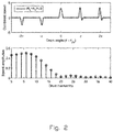
- the above functions are plotted versus the drum angle in three subplots in figure 1 .
- the x-axis represents the angle in radians beyond the filled 2 nd layer angle, here denoted by ⁇ 23 .
- the three subplots show the normalized deflections, their first derivatives and their second derivatives, respectively.
- the first derivatives represent the angular deviation from the tangent line while the second derivatives represent the line curvatures, or more precisely, the curvature deviation from the base curvature.
- the axial deflection steps are slightly larger than unity (line radius), reflecting the fact that the pitch in this example is chosen to be 2.5% larger than the line diameter. Also we have assumed that both the layer shift interval and the crossover intervals are 36 degrees.
- the combined speed has a lower peak (3.2) at the layer shift than the pure radial speed and that the individual harmonics components are much smaller in amplitude (in the order 0.5) than the peak speed itself (approximately 3.4).
- the amplitudes are relatively constant up to the 10 th harmonics, then they fall off and are quite small for the 20 th harmonics and above.
- the harmonics spectra for the normalized deflection and acceleration are not included here but they can easily be obtained by respective dividing and multiplying the speed spectrum by the harmonics number. We then find that the harmonics components of the deflection fall rapidly off with frequency while the acceleration can have large high frequency components. The maximum acceleration components are found around the 10 th harmonics for this particular case where the crossover angle covers 1/10 of a revolution.
- the next step is to study how the fast line responds to drum-induced motions, and in particular, how the placement and motion characteristics of a stabilizer influence the response.
- the study consists of two different approaches, the first being a linear, frequency-based study and the other a time based simulation model.
- the second approach is a numeric and non-linear simulation model being discussed at the end of this section.
- the first approach is based on the following simplifying assumptions.
- ⁇ is an internal friction parameter having the dimension of time.
- the factor 2 is included for convenience, to achieve some simplification in subsequent equations. This kind of damping term gives a damping rate with drops rapidly with frequency. It is possible even within the frame of linearity to change the line damping characteristics by considering ⁇ as a function of frequency and tension. But here we shall assume it is constant.
- Energy transmission along a transmission line can always be expressed as the product of a forcing variable and a motion variable.
- the motion variable is the transversal speed
- a wide class of lumped impedance elements can be characterized by its mass M , its damping coefficient B and the stiffness S of an optional spring.
- the above single degree of freedom (DOF) lumped impedance can be generalized to include multiple masses and coupling elements between the line and a fixed point. It can be shown that the impedance of an n-DOF system can be found by the following recursion formula.
- Z s , i j ⁇ M i + Z c , i ⁇ 1 + Z s , i ⁇ 1 ⁇ 1 ⁇ 1
- Z c,i is the coupling impedance between masses M i and M i -1 and the higher index is closer to the line.
- the coordinate system is here chosen so that the longitudinal location variable z equals 0 at the fast sheave and - L at the drum.
- the amplitudes a and b therefore represent the amplitudes of the incident and reflected waves, respectively.
- these frequencies are the natural (harmonic resonance) frequencies of the classical lossless string.
- this normalized impedance can reach very high values, maybe hundred or more.
- the dynamic transversal deflection and speeds can reach very high values if one the excitation frequencies, which are even multiples of the drum rotation frequency, matches one of the above string resonance frequencies.
- the special tension force is chosen for convenience, so that the wave propagation speed and the harmonic frequencies become round numbers.
- This tension force represents a typical line load when the hook load includes a drill string of moderate weight.
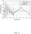
- the modulus of the normalized line impedance at the drum position is visualized in figure 3 for three cases.
- the first case, represented by the dotted curve, is without any stabilizer.
- the reduction of the peak heights with increasing frequency is a consequence of the bending induced damping, which increases rapidly with frequency.
- the logarithmic amplitude scale is used for visualizing the extreme differences in the dynamic line response. With the assumed internal line damping the response spans 5-6 orders of magnitude, from the maxima at the resonance frequencies to the minima at the anti-resonance frequencies. At the latter frequencies the force response is nearly zero, meaning that the line behaves as if it is not present.
- the second case represents a stabilizer without damping.
- the stabilizer mass changes the line response dramatically.
- the most pronounced difference is that a new wide resonance peak appears at a frequency slightly higher than the 10 th harmonics of the stabilizer-less spectrum.
- This peak is the first one in a series of new, regularly spaced frequency peaks being the result of the mass being so close to the drum and so far away from the fixed fast sheave.
- the third case represented by the solid curve, is with added stabilizer damping.
- the extra damping reduces the lowest resonance peaks substantially, almost by a factor 50.
- the damping has only a small effect on the response above the new resonance peak. This can be explained by the fact that the high line damping makes the wave being reflected from the fast sheave is heavily attenuated when it reaches the stabilizer.
- Case 2 (without damping) fairly well represents the impact on radial vibrations by the kind of stabilizer being used today. This is because there is virtually no friction restricting the stabilizer motion in the radial direction.
- the last case with damping is intended to simulate the action of current stabilizers on axial vibrations, although the effective level of the actual Coulomb friction is very uncertain.
- Reducing the stabilizer inertia is another way of reducing the resonance peaks in the band between the frequencies T / 4 ⁇ 2 lM and T / 4 ml 2 .
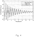
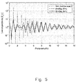
- the mechanical mass can probably be decreased from today's typical value of 80 kg down to maybe half its value simply by a redesign of the roller assembly. The effect of such a reduction is visualized in figure 5 . Notice that a mass reduction also increases the resonance frequency, proportionally to 1 / M .
- FIG. 1 Schematic side view and top view of a hoisting system 1 according to the present invention is shown comprising a fast line 2 with a winch, here only shown as a drum 4, fast sheave 6 and stabilizer 8 are shown in figure 7 .
- the use of two identical and perpendicular dampers 10 ensures equal damping in the two transversal directions.
- the roller assembly 14 is here shown with a double set of twin rollers 16 with V-shaped raceways 18, but other types of roller assemblies are possible, using other numbers (minimum 2) and shapes of rollers.
- Not shown in the schematic views is the anchoring of the telescopic dampers to the rig structure.
- the schematic drawings also lack means, typically a rod or wires, for keeping the vertical location of the roller assembly.
- this guide rod may be substantially parallel to the line, sufficiently stiff and hinged with a universal joint near the fast sheave to allow transversal motions but prevent rotational motions of the roller assembly.
- the support structure to which the stabilizer and the wire rope guiding sheave are connected, is not shown in the figure.
- the dampers 10, here visualized as small telescopic cylinders, can have three levels of control. These levels are discussed briefly below.
- passive damper here means that it has fixed energy dissipation characteristics.
- a candidate for such damper is a shock absorber used as in the suspension of automotive vehicles.
- a drawback of such shock absorbers is that they have rather non-linear and asymmetric characteristics. The asymmetry means that the damping force is different for compression speeds than for extensional speed.
- vehicle shock absorbers seem to have a speed rating of typically 0.5 m/s, which is substantially lower than what may be needed in some embodiments of the present invention.
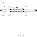
- the damper 10 comprises a standard hydraulic cylinder 20 (hatched inner area representing oil) with hydraulic ports 22 in both ends. But instead of having only one piston rod it has two rods 24, 26 of equal diameters. Only the left one carries the axial load. The air filled cylinder to the right protects the dummy rod and carries the reactive load from the main cylinder. A not shown rubber bellow around the air exposed part of the left rod is recommended for protecting this rod too.
- the main advantages of this design are 1) the inner volume is constant thus creating zero extension force if a common pressure is applied in both chambers and 2) the damping characteristics are the same in both speed directions.
- the term semi-active means that the energy dissipating characteristics can be changed rather rapidly to adjust the damping characteristics dynamically.
- a possible candidate for such a damper is controllable shock absorbers found in some high end car brands, provided that the speed and force ratings are adequate.
- Key words are smart fluids and electric control of the damper characteristics.
- the most common smart fluid is magnetorheological fluids. As the name indicates, its viscous properties can be changed almost instantaneously by a magnetic field. It is mostly the gel strength and thereby the apparent Coulomb friction that can be controlled by the magnetic field.
- a high band width control of the rheology can, in principal at least, be used to mimic a linear damper action.
- the balanced cylinder already mentioned as a passive damper option could also be regarded as a semi-active damper, especially if it includes an external, controllable bypass valve in parallel with a metering orifice through the piston.
- the damping can be controlled in many ways.
- One of the simpler options is a stepwise flow resistance control, for instance by opening or closing one or more external bypass lines.
- a more advance option is to use an external metering valve that can be proportionally controlled to provide a continuous variation of the flow resistance.
- the oil volume should be connected to an external oil reservoir with an optional gas accumulator. This reservoir should preferably be connected to the center of the external bypass flow line to hinder an oscillating accumulator flow.
- An alternative to hydraulic dampers is eddy current brakes.
- Such brakes have fairly linear characteristics, at least for moderate speeds and magnetization levels. It means that the braking force is proportional to the speed and to the stator current producing the magnetic field.
- the set speed, v set can either be set to zero, or to the fraction of the low pass filtered lateral speeds at the drum: v r,lp l / L and v a,l l / L. Notice that the integrator gain, I , has the dimension of linear stiffness whereas the derivative gain D has the dimension of mass.
- the above controller impedance represents the ratio of telescopic force divided by telescopic speed.
- the basic moving element is a rotating motor connected to the linear motion by a gear mechanism.
- ⁇ 1 and ⁇ 1 denote respective the deviations from pure radial and longitudinal directions for damper 1 having a telescopic impedance Z c ,1
- ⁇ 2 , ⁇ 2 and Z c, 2 be the corresponding parameters for damper 2.
- longitudinal direction is here meant the direction of line between center or rollers and the pivoting point at the top of the stabilizer bar. This direction may differ slightly from the longitudinal line direction.
- a similar reduction of the telescopic stroke, speed and acceleration is obtained by a slant angle.
- the reduction factor is sin( ⁇ ).
- ⁇ ⁇ /2, is that the guide rod must handle an increasing longitudinal force equal to F t cot ⁇ , F t being the resulting transversal force. If this rod is fastened to the roller assembly with an offset distance between its neutral axis and the fast line, then the force will also generate a bending moment being proportional to the offset and to the longitudinal force. The required rigidity and weight of the guide rod will therefore increase with decreasing slant angle.
- a simulation model is developed both for supporting the linear theory above and for being able to calculate the effect a realistic stabilizers having non-linear damping characteristics.
- the model is based on the convective version of the wave equation (18).
- the convection which means that the line is moving longitudinally with a constant translation speed V , is obtained by substituting the partial time derivatives by the so-called material derivatives: ⁇ / ⁇ t ⁇ ⁇ / ⁇ t + V ⁇ / ⁇ x .
- the end nodes, representing the drum and fast sheaves, are modelled with nearly infinite masses to prevent force induced lateral motion.
- the stabilizer node is also specially treated with a mass ⁇ M + M s and a speed dependent external damping force.
- ⁇ is a speed exponent
- ⁇ 0 is a small transition speed (typically 0.01 m/s) included for numerical reasons.
- This speed exponent equals 1 for linear damping, 0 for Coulomb friction and 2 for a quadratic damping but it can have any value between the two last extremes.
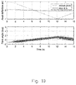
- the simulation model is implemented in Simulink, a powerful simulation tool under the Matlab umbrella. Examples of simulation results are shown in figures 9 and 10 , representing the respective cases without any stabilizer and with one stabilizer having two identical dampers mounted as visualized in figure 7 .
- the line parameters are the same as in the numerical example used for the linear analysis.
- Each damper is a passive hydraulic one as visualized in figure 8 .
- the simulation results basically confirm what was predicted by linear theory.
- the cross-over frequency hits a line resonance, large vibrations build up in the line.
- the sharp resonances predicted by the linear theory also imply that it takes time to reach steady state vibrations.
- steady state is not completely reached before the drum spooling enters layer 3 and the excitation direction reverses.
- This sudden polarity reversal of speed excitation pulses explains why the dynamic line vibrations temporarily reduce when the spooling starts on the 3 rd layer.
- Simulation with extended time intervals not shown here, show that the severe line vibrations pick up again beyond 16 s.
- a preferred set of fast line dampers are two balanced hydraulic cylinders as visualized and mounted in figure 7 , right and left, respectively. Key parameters for the roller assembly and cylinders are
- the suggested metering area represents a progressive damping.
- the Bernoulli equation for pressure drop applies, that is, ⁇ p ⁇ 0.5 ⁇
- ⁇ ⁇ 850 kgm -3 is the hydraulic fluid density
- the roller assembly which connects the dampers to the fast line, is not discussed in details here because there are many designs that will work almost equally well.
- the suggested variant in figure 5 can probably be designed to a mass of less than 30 kg resulting in a total mass of one dampener less than 40 kg.
- elastomer (rubber) sleeves in the couplings, similar to those used in many vehicle shock absorbers.
- Such coupling will act as mechanical low pass filter reducing transfer of high frequency vibration components and transmitting mainly the low frequency components.
- Noise reduction and smoother roll action can also be obtained by substituting parts of the V-profile of the rollers by a U-profile having a curvature radius matching the maximum radius of the line.
Landscapes
- Engineering & Computer Science (AREA)
- Life Sciences & Earth Sciences (AREA)
- Geology (AREA)
- Mining & Mineral Resources (AREA)
- Mechanical Engineering (AREA)
- Physics & Mathematics (AREA)
- Environmental & Geological Engineering (AREA)
- Fluid Mechanics (AREA)
- General Life Sciences & Earth Sciences (AREA)
- Geochemistry & Mineralogy (AREA)
- Vibration Prevention Devices (AREA)
Priority Applications (3)
| Application Number | Priority Date | Filing Date | Title |
|---|---|---|---|
| DK16157498.3T DK3211175T3 (en) | 2016-02-26 | 2016-02-26 | Hoisting system and method for operating the same |
| EP16157498.3A EP3211175B1 (de) | 2016-02-26 | 2016-02-26 | Hubsystem und verfahren zum betrieb davon |
| PCT/NO2017/050050 WO2017146592A1 (en) | 2016-02-26 | 2017-02-22 | Hoisting system and method for operating the same |
Applications Claiming Priority (1)
| Application Number | Priority Date | Filing Date | Title |
|---|---|---|---|
| EP16157498.3A EP3211175B1 (de) | 2016-02-26 | 2016-02-26 | Hubsystem und verfahren zum betrieb davon |
Publications (2)
| Publication Number | Publication Date |
|---|---|
| EP3211175A1 true EP3211175A1 (de) | 2017-08-30 |
| EP3211175B1 EP3211175B1 (de) | 2022-03-30 |
Family
ID=55484829
Family Applications (1)
| Application Number | Title | Priority Date | Filing Date |
|---|---|---|---|
| EP16157498.3A Active EP3211175B1 (de) | 2016-02-26 | 2016-02-26 | Hubsystem und verfahren zum betrieb davon |
Country Status (3)
| Country | Link |
|---|---|
| EP (1) | EP3211175B1 (de) |
| DK (1) | DK3211175T3 (de) |
| WO (1) | WO2017146592A1 (de) |
Cited By (1)
| Publication number | Priority date | Publication date | Assignee | Title |
|---|---|---|---|---|
| CN113336100A (zh) * | 2021-05-18 | 2021-09-03 | 武汉船用机械有限责任公司 | 一种钢丝绳防脱槽装置 |
Families Citing this family (3)
| Publication number | Priority date | Publication date | Assignee | Title |
|---|---|---|---|---|
| US11187049B2 (en) | 2018-09-06 | 2021-11-30 | Schlumberger Technology Corporation | Fingerboard |
| CN113326602B (zh) * | 2020-11-13 | 2023-05-30 | 内蒙古电力(集团)有限责任公司内蒙古电力科学研究院分公司 | 一种基于系统敏感系数的防振锤设计方法 |
| FR3144972A1 (fr) * | 2023-01-18 | 2024-07-19 | Flying Whales | Dispositif d’amortissement d’oscillations pendulaires de la charge à embarquer en soute d’un dirigeable dédié pour le transport de charges lourdes |
Citations (7)
| Publication number | Priority date | Publication date | Assignee | Title |
|---|---|---|---|---|
| US2238398A (en) * | 1937-05-22 | 1941-04-15 | John E Reed | Line spooler |
| US2565693A (en) * | 1949-10-15 | 1951-08-28 | Charles T Lewis | Wire line guide and stabilizer |
| US2681793A (en) * | 1948-11-13 | 1954-06-22 | Byron Jackson Co | Wire line guide |
| PL158970B1 (pl) * | 1988-12-21 | 1992-10-30 | Polskie Gornictwo Naftowe | wiertnicy PL |
| WO2014209131A1 (en) | 2013-06-25 | 2014-12-31 | National Oilwell Varco Norway As | System for hoisting a load on an offshore rig |
| US20150275647A1 (en) * | 2014-03-25 | 2015-10-01 | Canrig Drilling Technology Ltd. | Stiction control |
| US20150353331A1 (en) * | 2014-06-04 | 2015-12-10 | National Oilwell Varco, L.P. | Line stabilizer |
Family Cites Families (2)
| Publication number | Priority date | Publication date | Assignee | Title |
|---|---|---|---|---|
| US2190880A (en) * | 1938-01-21 | 1940-02-20 | Perry M Moss | Draw works line controller |
| US2744696A (en) * | 1955-04-14 | 1956-05-08 | Moore Corp Lee C | Fast line guide |
-
2016
- 2016-02-26 EP EP16157498.3A patent/EP3211175B1/de active Active
- 2016-02-26 DK DK16157498.3T patent/DK3211175T3/da active
-
2017
- 2017-02-22 WO PCT/NO2017/050050 patent/WO2017146592A1/en not_active Ceased
Patent Citations (7)
| Publication number | Priority date | Publication date | Assignee | Title |
|---|---|---|---|---|
| US2238398A (en) * | 1937-05-22 | 1941-04-15 | John E Reed | Line spooler |
| US2681793A (en) * | 1948-11-13 | 1954-06-22 | Byron Jackson Co | Wire line guide |
| US2565693A (en) * | 1949-10-15 | 1951-08-28 | Charles T Lewis | Wire line guide and stabilizer |
| PL158970B1 (pl) * | 1988-12-21 | 1992-10-30 | Polskie Gornictwo Naftowe | wiertnicy PL |
| WO2014209131A1 (en) | 2013-06-25 | 2014-12-31 | National Oilwell Varco Norway As | System for hoisting a load on an offshore rig |
| US20150275647A1 (en) * | 2014-03-25 | 2015-10-01 | Canrig Drilling Technology Ltd. | Stiction control |
| US20150353331A1 (en) * | 2014-06-04 | 2015-12-10 | National Oilwell Varco, L.P. | Line stabilizer |
Cited By (2)
| Publication number | Priority date | Publication date | Assignee | Title |
|---|---|---|---|---|
| CN113336100A (zh) * | 2021-05-18 | 2021-09-03 | 武汉船用机械有限责任公司 | 一种钢丝绳防脱槽装置 |
| CN113336100B (zh) * | 2021-05-18 | 2023-09-05 | 武汉船用机械有限责任公司 | 一种钢丝绳防脱槽装置 |
Also Published As
| Publication number | Publication date |
|---|---|
| EP3211175B1 (de) | 2022-03-30 |
| WO2017146592A1 (en) | 2017-08-31 |
| DK3211175T3 (en) | 2022-06-20 |
Similar Documents
| Publication | Publication Date | Title |
|---|---|---|
| EP3211175B1 (de) | Hubsystem und verfahren zum betrieb davon | |
| US7748474B2 (en) | Active vibration control for subterranean drilling operations | |
| Richards et al. | Passive reduction of gear mesh vibration using a periodic drive shaft | |
| Zhou et al. | Experimental investigation of correction factor for VIV amplitude of flexible bridges from an aeroelastic model and its 1: 1 section model | |
| Kluger et al. | Robust energy harvesting from walking vibrations by means of nonlinear cantilever beams | |
| Zhu et al. | Recent advances, future application and challenges in nonlinear flutter theory of long span bridges | |
| Cao et al. | Discrete viscous dampers for multi-mode vortex-induced vibration control of long-span suspension bridges | |
| Vandiver et al. | The effectiveness of helical strakes in the suppression of high-mode-number VIV | |
| US20220412424A1 (en) | Damper | |
| US10422442B2 (en) | Method for suppression of resonant vibrations in subsea pipelines | |
| Cao et al. | A multi-stable nonlinear energy sink for torsional vibration of the rotor system | |
| Liu et al. | A method of reinforcement and vibration reduction of girder bridges using shape memory alloy cables | |
| CN113445412A (zh) | 一种控制大跨度桥梁主梁涡激振动的减振装置 | |
| Egger et al. | Modeling and experimental validation of a multiple‐mass‐particle impact damper for controlling stay‐cable oscillations | |
| Wang et al. | Experimental and numerical study of a novel low-frequency tuned mass damper-inerter | |
| Yuan et al. | Viscous Fluid Dissipation for Filtering Poor Bandgaps and Achieving Low‐Frequency Bandgaps in Metamaterials | |
| McManus et al. | Damping in cantilevered traffic signal structures under forced vibration | |
| Zare et al. | Finite element analysis of drillstring lateral vibration | |
| Li et al. | Modal analysis of coupled vibration of belt drive systems | |
| Zhou et al. | Match of negative stiffness and viscous damping in a passive damper for cable vibration control | |
| Alshaer et al. | Enhancing seismic performance of cable-stayed bridges using tuned mass dampers | |
| US20250108581A1 (en) | Constrained layer damper for reducing global vibrations of tubular structures | |
| Kyllingstad | A Study Of Instabilities Observed When Heave Compensating Deepsea Risers | |
| Kyllingstad | A Study of the Dynamics of Lateral Fastline Vibrations | |
| JP4337393B2 (ja) | 振動制御方法 |
Legal Events
| Date | Code | Title | Description |
|---|---|---|---|
| PUAI | Public reference made under article 153(3) epc to a published international application that has entered the european phase |
Free format text: ORIGINAL CODE: 0009012 |
|
| STAA | Information on the status of an ep patent application or granted ep patent |
Free format text: STATUS: THE APPLICATION HAS BEEN PUBLISHED |
|
| AK | Designated contracting states |
Kind code of ref document: A1 Designated state(s): AL AT BE BG CH CY CZ DE DK EE ES FI FR GB GR HR HU IE IS IT LI LT LU LV MC MK MT NL NO PL PT RO RS SE SI SK SM TR |
|
| AX | Request for extension of the european patent |
Extension state: BA ME |
|
| STAA | Information on the status of an ep patent application or granted ep patent |
Free format text: STATUS: REQUEST FOR EXAMINATION WAS MADE |
|
| 17P | Request for examination filed |
Effective date: 20180228 |
|
| RBV | Designated contracting states (corrected) |
Designated state(s): AL AT BE BG CH CY CZ DE DK EE ES FI FR GB GR HR HU IE IS IT LI LT LU LV MC MK MT NL NO PL PT RO RS SE SI SK SM TR |
|
| STAA | Information on the status of an ep patent application or granted ep patent |
Free format text: STATUS: EXAMINATION IS IN PROGRESS |
|
| 17Q | First examination report despatched |
Effective date: 20190409 |
|
| GRAP | Despatch of communication of intention to grant a patent |
Free format text: ORIGINAL CODE: EPIDOSNIGR1 |
|
| STAA | Information on the status of an ep patent application or granted ep patent |
Free format text: STATUS: GRANT OF PATENT IS INTENDED |
|
| INTG | Intention to grant announced |
Effective date: 20211108 |
|
| GRAS | Grant fee paid |
Free format text: ORIGINAL CODE: EPIDOSNIGR3 |
|
| GRAA | (expected) grant |
Free format text: ORIGINAL CODE: 0009210 |
|
| STAA | Information on the status of an ep patent application or granted ep patent |
Free format text: STATUS: THE PATENT HAS BEEN GRANTED |
|
| AK | Designated contracting states |
Kind code of ref document: B1 Designated state(s): AL AT BE BG CH CY CZ DE DK EE ES FI FR GB GR HR HU IE IS IT LI LT LU LV MC MK MT NL NO PL PT RO RS SE SI SK SM TR |
|
| REG | Reference to a national code |
Ref country code: GB Ref legal event code: FG4D |
|
| REG | Reference to a national code |
Ref country code: CH Ref legal event code: EP |
|
| REG | Reference to a national code |
Ref country code: AT Ref legal event code: REF Ref document number: 1479348 Country of ref document: AT Kind code of ref document: T Effective date: 20220415 |
|
| REG | Reference to a national code |
Ref country code: DE Ref legal event code: R096 Ref document number: 602016070427 Country of ref document: DE |
|
| REG | Reference to a national code |
Ref country code: IE Ref legal event code: FG4D |
|
| REG | Reference to a national code |
Ref country code: DK Ref legal event code: T3 Effective date: 20220613 |
|
| REG | Reference to a national code |
Ref country code: NL Ref legal event code: FP |
|
| REG | Reference to a national code |
Ref country code: LT Ref legal event code: MG9D |
|
| PG25 | Lapsed in a contracting state [announced via postgrant information from national office to epo] |
Ref country code: SE Free format text: LAPSE BECAUSE OF FAILURE TO SUBMIT A TRANSLATION OF THE DESCRIPTION OR TO PAY THE FEE WITHIN THE PRESCRIBED TIME-LIMIT Effective date: 20220330 Ref country code: RS Free format text: LAPSE BECAUSE OF FAILURE TO SUBMIT A TRANSLATION OF THE DESCRIPTION OR TO PAY THE FEE WITHIN THE PRESCRIBED TIME-LIMIT Effective date: 20220330 Ref country code: LT Free format text: LAPSE BECAUSE OF FAILURE TO SUBMIT A TRANSLATION OF THE DESCRIPTION OR TO PAY THE FEE WITHIN THE PRESCRIBED TIME-LIMIT Effective date: 20220330 Ref country code: HR Free format text: LAPSE BECAUSE OF FAILURE TO SUBMIT A TRANSLATION OF THE DESCRIPTION OR TO PAY THE FEE WITHIN THE PRESCRIBED TIME-LIMIT Effective date: 20220330 Ref country code: BG Free format text: LAPSE BECAUSE OF FAILURE TO SUBMIT A TRANSLATION OF THE DESCRIPTION OR TO PAY THE FEE WITHIN THE PRESCRIBED TIME-LIMIT Effective date: 20220630 |
|
| REG | Reference to a national code |
Ref country code: AT Ref legal event code: MK05 Ref document number: 1479348 Country of ref document: AT Kind code of ref document: T Effective date: 20220330 Ref country code: NO Ref legal event code: T2 Effective date: 20220330 |
|
| PG25 | Lapsed in a contracting state [announced via postgrant information from national office to epo] |
Ref country code: LV Free format text: LAPSE BECAUSE OF FAILURE TO SUBMIT A TRANSLATION OF THE DESCRIPTION OR TO PAY THE FEE WITHIN THE PRESCRIBED TIME-LIMIT Effective date: 20220330 Ref country code: GR Free format text: LAPSE BECAUSE OF FAILURE TO SUBMIT A TRANSLATION OF THE DESCRIPTION OR TO PAY THE FEE WITHIN THE PRESCRIBED TIME-LIMIT Effective date: 20220701 Ref country code: FI Free format text: LAPSE BECAUSE OF FAILURE TO SUBMIT A TRANSLATION OF THE DESCRIPTION OR TO PAY THE FEE WITHIN THE PRESCRIBED TIME-LIMIT Effective date: 20220330 |
|
| PG25 | Lapsed in a contracting state [announced via postgrant information from national office to epo] |
Ref country code: SM Free format text: LAPSE BECAUSE OF FAILURE TO SUBMIT A TRANSLATION OF THE DESCRIPTION OR TO PAY THE FEE WITHIN THE PRESCRIBED TIME-LIMIT Effective date: 20220330 Ref country code: SK Free format text: LAPSE BECAUSE OF FAILURE TO SUBMIT A TRANSLATION OF THE DESCRIPTION OR TO PAY THE FEE WITHIN THE PRESCRIBED TIME-LIMIT Effective date: 20220330 Ref country code: RO Free format text: LAPSE BECAUSE OF FAILURE TO SUBMIT A TRANSLATION OF THE DESCRIPTION OR TO PAY THE FEE WITHIN THE PRESCRIBED TIME-LIMIT Effective date: 20220330 Ref country code: PT Free format text: LAPSE BECAUSE OF FAILURE TO SUBMIT A TRANSLATION OF THE DESCRIPTION OR TO PAY THE FEE WITHIN THE PRESCRIBED TIME-LIMIT Effective date: 20220801 Ref country code: ES Free format text: LAPSE BECAUSE OF FAILURE TO SUBMIT A TRANSLATION OF THE DESCRIPTION OR TO PAY THE FEE WITHIN THE PRESCRIBED TIME-LIMIT Effective date: 20220330 Ref country code: EE Free format text: LAPSE BECAUSE OF FAILURE TO SUBMIT A TRANSLATION OF THE DESCRIPTION OR TO PAY THE FEE WITHIN THE PRESCRIBED TIME-LIMIT Effective date: 20220330 Ref country code: CZ Free format text: LAPSE BECAUSE OF FAILURE TO SUBMIT A TRANSLATION OF THE DESCRIPTION OR TO PAY THE FEE WITHIN THE PRESCRIBED TIME-LIMIT Effective date: 20220330 Ref country code: AT Free format text: LAPSE BECAUSE OF FAILURE TO SUBMIT A TRANSLATION OF THE DESCRIPTION OR TO PAY THE FEE WITHIN THE PRESCRIBED TIME-LIMIT Effective date: 20220330 |
|
| PG25 | Lapsed in a contracting state [announced via postgrant information from national office to epo] |
Ref country code: PL Free format text: LAPSE BECAUSE OF FAILURE TO SUBMIT A TRANSLATION OF THE DESCRIPTION OR TO PAY THE FEE WITHIN THE PRESCRIBED TIME-LIMIT Effective date: 20220330 Ref country code: IS Free format text: LAPSE BECAUSE OF FAILURE TO SUBMIT A TRANSLATION OF THE DESCRIPTION OR TO PAY THE FEE WITHIN THE PRESCRIBED TIME-LIMIT Effective date: 20220730 Ref country code: AL Free format text: LAPSE BECAUSE OF FAILURE TO SUBMIT A TRANSLATION OF THE DESCRIPTION OR TO PAY THE FEE WITHIN THE PRESCRIBED TIME-LIMIT Effective date: 20220330 |
|
| REG | Reference to a national code |
Ref country code: DE Ref legal event code: R097 Ref document number: 602016070427 Country of ref document: DE |
|
| REG | Reference to a national code |
Ref country code: NO Ref legal event code: CHAD Owner name: GRANT PRIDECO, US |
|
| PLBE | No opposition filed within time limit |
Free format text: ORIGINAL CODE: 0009261 |
|
| STAA | Information on the status of an ep patent application or granted ep patent |
Free format text: STATUS: NO OPPOSITION FILED WITHIN TIME LIMIT |
|
| 26N | No opposition filed |
Effective date: 20230103 |
|
| REG | Reference to a national code |
Ref country code: GB Ref legal event code: 732E Free format text: REGISTERED BETWEEN 20230209 AND 20230215 |
|
| PG25 | Lapsed in a contracting state [announced via postgrant information from national office to epo] |
Ref country code: SI Free format text: LAPSE BECAUSE OF FAILURE TO SUBMIT A TRANSLATION OF THE DESCRIPTION OR TO PAY THE FEE WITHIN THE PRESCRIBED TIME-LIMIT Effective date: 20220330 |
|
| P01 | Opt-out of the competence of the unified patent court (upc) registered |
Effective date: 20230530 |
|
| PG25 | Lapsed in a contracting state [announced via postgrant information from national office to epo] |
Ref country code: IT Free format text: LAPSE BECAUSE OF FAILURE TO SUBMIT A TRANSLATION OF THE DESCRIPTION OR TO PAY THE FEE WITHIN THE PRESCRIBED TIME-LIMIT Effective date: 20220330 |
|
| REG | Reference to a national code |
Ref country code: DE Ref legal event code: R119 Ref document number: 602016070427 Country of ref document: DE |
|
| PG25 | Lapsed in a contracting state [announced via postgrant information from national office to epo] |
Ref country code: MC Free format text: LAPSE BECAUSE OF FAILURE TO SUBMIT A TRANSLATION OF THE DESCRIPTION OR TO PAY THE FEE WITHIN THE PRESCRIBED TIME-LIMIT Effective date: 20220330 |
|
| REG | Reference to a national code |
Ref country code: CH Ref legal event code: PL |
|
| REG | Reference to a national code |
Ref country code: BE Ref legal event code: MM Effective date: 20230228 |
|
| PG25 | Lapsed in a contracting state [announced via postgrant information from national office to epo] |
Ref country code: LU Free format text: LAPSE BECAUSE OF NON-PAYMENT OF DUE FEES Effective date: 20230226 Ref country code: LI Free format text: LAPSE BECAUSE OF NON-PAYMENT OF DUE FEES Effective date: 20230228 Ref country code: CH Free format text: LAPSE BECAUSE OF NON-PAYMENT OF DUE FEES Effective date: 20230228 |
|
| REG | Reference to a national code |
Ref country code: IE Ref legal event code: MM4A |
|
| PG25 | Lapsed in a contracting state [announced via postgrant information from national office to epo] |
Ref country code: IE Free format text: LAPSE BECAUSE OF NON-PAYMENT OF DUE FEES Effective date: 20230226 Ref country code: FR Free format text: LAPSE BECAUSE OF NON-PAYMENT OF DUE FEES Effective date: 20230228 Ref country code: DE Free format text: LAPSE BECAUSE OF NON-PAYMENT OF DUE FEES Effective date: 20230901 |
|
| PG25 | Lapsed in a contracting state [announced via postgrant information from national office to epo] |
Ref country code: BE Free format text: LAPSE BECAUSE OF NON-PAYMENT OF DUE FEES Effective date: 20230228 |
|
| PG25 | Lapsed in a contracting state [announced via postgrant information from national office to epo] |
Ref country code: CY Free format text: LAPSE BECAUSE OF FAILURE TO SUBMIT A TRANSLATION OF THE DESCRIPTION OR TO PAY THE FEE WITHIN THE PRESCRIBED TIME-LIMIT; INVALID AB INITIO Effective date: 20160226 |
|
| PG25 | Lapsed in a contracting state [announced via postgrant information from national office to epo] |
Ref country code: HU Free format text: LAPSE BECAUSE OF FAILURE TO SUBMIT A TRANSLATION OF THE DESCRIPTION OR TO PAY THE FEE WITHIN THE PRESCRIBED TIME-LIMIT; INVALID AB INITIO Effective date: 20160226 |
|
| PG25 | Lapsed in a contracting state [announced via postgrant information from national office to epo] |
Ref country code: TR Free format text: LAPSE BECAUSE OF FAILURE TO SUBMIT A TRANSLATION OF THE DESCRIPTION OR TO PAY THE FEE WITHIN THE PRESCRIBED TIME-LIMIT Effective date: 20220330 |
|
| PGFP | Annual fee paid to national office [announced via postgrant information from national office to epo] |
Ref country code: NL Payment date: 20260106 Year of fee payment: 11 |
|
| PGFP | Annual fee paid to national office [announced via postgrant information from national office to epo] |
Ref country code: GB Payment date: 20260106 Year of fee payment: 11 |
|
| PGFP | Annual fee paid to national office [announced via postgrant information from national office to epo] |
Ref country code: NO Payment date: 20260211 Year of fee payment: 11 Ref country code: DK Payment date: 20260213 Year of fee payment: 11 |