EP3211298B1 - Appareil d'éclairage et phare de véhicule comprenant ledit appareil - Google Patents
Appareil d'éclairage et phare de véhicule comprenant ledit appareil Download PDFInfo
- Publication number
- EP3211298B1 EP3211298B1 EP15853404.0A EP15853404A EP3211298B1 EP 3211298 B1 EP3211298 B1 EP 3211298B1 EP 15853404 A EP15853404 A EP 15853404A EP 3211298 B1 EP3211298 B1 EP 3211298B1
- Authority
- EP
- European Patent Office
- Prior art keywords
- light guide
- guide member
- light
- light source
- lighting device
- Prior art date
- Legal status (The legal status is an assumption and is not a legal conclusion. Google has not performed a legal analysis and makes no representation as to the accuracy of the status listed.)
- Active
Links
Images


Classifications
-
- F—MECHANICAL ENGINEERING; LIGHTING; HEATING; WEAPONS; BLASTING
- F21—LIGHTING
- F21S—NON-PORTABLE LIGHTING DEVICES; SYSTEMS THEREOF; VEHICLE LIGHTING DEVICES SPECIALLY ADAPTED FOR VEHICLE EXTERIORS
- F21S43/00—Signalling devices specially adapted for vehicle exteriors, e.g. brake lamps, direction indicator lights or reversing lights
-
- F—MECHANICAL ENGINEERING; LIGHTING; HEATING; WEAPONS; BLASTING
- F21—LIGHTING
- F21S—NON-PORTABLE LIGHTING DEVICES; SYSTEMS THEREOF; VEHICLE LIGHTING DEVICES SPECIALLY ADAPTED FOR VEHICLE EXTERIORS
- F21S43/00—Signalling devices specially adapted for vehicle exteriors, e.g. brake lamps, direction indicator lights or reversing lights
- F21S43/10—Signalling devices specially adapted for vehicle exteriors, e.g. brake lamps, direction indicator lights or reversing lights characterised by the light source
- F21S43/13—Signalling devices specially adapted for vehicle exteriors, e.g. brake lamps, direction indicator lights or reversing lights characterised by the light source characterised by the type of light source
- F21S43/14—Light emitting diodes [LED]
-
- B—PERFORMING OPERATIONS; TRANSPORTING
- B60—VEHICLES IN GENERAL
- B60Q—ARRANGEMENT OF SIGNALLING OR LIGHTING DEVICES, THE MOUNTING OR SUPPORTING THEREOF OR CIRCUITS THEREFOR, FOR VEHICLES IN GENERAL
- B60Q1/00—Arrangement of optical signalling or lighting devices, the mounting or supporting thereof or circuits therefor
-
- B—PERFORMING OPERATIONS; TRANSPORTING
- B60—VEHICLES IN GENERAL
- B60Q—ARRANGEMENT OF SIGNALLING OR LIGHTING DEVICES, THE MOUNTING OR SUPPORTING THEREOF OR CIRCUITS THEREFOR, FOR VEHICLES IN GENERAL
- B60Q1/00—Arrangement of optical signalling or lighting devices, the mounting or supporting thereof or circuits therefor
- B60Q1/02—Arrangement of optical signalling or lighting devices, the mounting or supporting thereof or circuits therefor the devices being primarily intended to illuminate the way ahead or to illuminate other areas of way or environments
-
- F—MECHANICAL ENGINEERING; LIGHTING; HEATING; WEAPONS; BLASTING
- F21—LIGHTING
- F21K—NON-ELECTRIC LIGHT SOURCES USING LUMINESCENCE; LIGHT SOURCES USING ELECTROCHEMILUMINESCENCE; LIGHT SOURCES USING CHARGES OF COMBUSTIBLE MATERIAL; LIGHT SOURCES USING SEMICONDUCTOR DEVICES AS LIGHT-GENERATING ELEMENTS; LIGHT SOURCES NOT OTHERWISE PROVIDED FOR
- F21K9/00—Light sources using semiconductor devices as light-generating elements, e.g. using light-emitting diodes [LED] or lasers
- F21K9/60—Optical arrangements integrated in the light source, e.g. for improving the colour rendering index or the light extraction
- F21K9/61—Optical arrangements integrated in the light source, e.g. for improving the colour rendering index or the light extraction using light guides
-
- F—MECHANICAL ENGINEERING; LIGHTING; HEATING; WEAPONS; BLASTING
- F21—LIGHTING
- F21K—NON-ELECTRIC LIGHT SOURCES USING LUMINESCENCE; LIGHT SOURCES USING ELECTROCHEMILUMINESCENCE; LIGHT SOURCES USING CHARGES OF COMBUSTIBLE MATERIAL; LIGHT SOURCES USING SEMICONDUCTOR DEVICES AS LIGHT-GENERATING ELEMENTS; LIGHT SOURCES NOT OTHERWISE PROVIDED FOR
- F21K9/00—Light sources using semiconductor devices as light-generating elements, e.g. using light-emitting diodes [LED] or lasers
- F21K9/60—Optical arrangements integrated in the light source, e.g. for improving the colour rendering index or the light extraction
- F21K9/69—Details of refractors forming part of the light source
-
- F—MECHANICAL ENGINEERING; LIGHTING; HEATING; WEAPONS; BLASTING
- F21—LIGHTING
- F21S—NON-PORTABLE LIGHTING DEVICES; SYSTEMS THEREOF; VEHICLE LIGHTING DEVICES SPECIALLY ADAPTED FOR VEHICLE EXTERIORS
- F21S41/00—Illuminating devices specially adapted for vehicle exteriors, e.g. headlamps
- F21S41/10—Illuminating devices specially adapted for vehicle exteriors, e.g. headlamps characterised by the light source
- F21S41/14—Illuminating devices specially adapted for vehicle exteriors, e.g. headlamps characterised by the light source characterised by the type of light source
- F21S41/141—Light emitting diodes [LED]
-
- F—MECHANICAL ENGINEERING; LIGHTING; HEATING; WEAPONS; BLASTING
- F21—LIGHTING
- F21S—NON-PORTABLE LIGHTING DEVICES; SYSTEMS THEREOF; VEHICLE LIGHTING DEVICES SPECIALLY ADAPTED FOR VEHICLE EXTERIORS
- F21S41/00—Illuminating devices specially adapted for vehicle exteriors, e.g. headlamps
- F21S41/20—Illuminating devices specially adapted for vehicle exteriors, e.g. headlamps characterised by refractors, transparent cover plates, light guides or filters
- F21S41/24—Light guides
-
- F—MECHANICAL ENGINEERING; LIGHTING; HEATING; WEAPONS; BLASTING
- F21—LIGHTING
- F21S—NON-PORTABLE LIGHTING DEVICES; SYSTEMS THEREOF; VEHICLE LIGHTING DEVICES SPECIALLY ADAPTED FOR VEHICLE EXTERIORS
- F21S41/00—Illuminating devices specially adapted for vehicle exteriors, e.g. headlamps
- F21S41/20—Illuminating devices specially adapted for vehicle exteriors, e.g. headlamps characterised by refractors, transparent cover plates, light guides or filters
- F21S41/285—Refractors, transparent cover plates, light guides or filters not provided in groups F21S41/24 - F21S41/2805
-
- F—MECHANICAL ENGINEERING; LIGHTING; HEATING; WEAPONS; BLASTING
- F21—LIGHTING
- F21S—NON-PORTABLE LIGHTING DEVICES; SYSTEMS THEREOF; VEHICLE LIGHTING DEVICES SPECIALLY ADAPTED FOR VEHICLE EXTERIORS
- F21S41/00—Illuminating devices specially adapted for vehicle exteriors, e.g. headlamps
- F21S41/30—Illuminating devices specially adapted for vehicle exteriors, e.g. headlamps characterised by reflectors
-
- F—MECHANICAL ENGINEERING; LIGHTING; HEATING; WEAPONS; BLASTING
- F21—LIGHTING
- F21S—NON-PORTABLE LIGHTING DEVICES; SYSTEMS THEREOF; VEHICLE LIGHTING DEVICES SPECIALLY ADAPTED FOR VEHICLE EXTERIORS
- F21S43/00—Signalling devices specially adapted for vehicle exteriors, e.g. brake lamps, direction indicator lights or reversing lights
- F21S43/20—Signalling devices specially adapted for vehicle exteriors, e.g. brake lamps, direction indicator lights or reversing lights characterised by refractors, transparent cover plates, light guides or filters
- F21S43/235—Light guides
- F21S43/236—Light guides characterised by the shape of the light guide
- F21S43/239—Light guides characterised by the shape of the light guide plate-shaped
-
- F—MECHANICAL ENGINEERING; LIGHTING; HEATING; WEAPONS; BLASTING
- F21—LIGHTING
- F21S—NON-PORTABLE LIGHTING DEVICES; SYSTEMS THEREOF; VEHICLE LIGHTING DEVICES SPECIALLY ADAPTED FOR VEHICLE EXTERIORS
- F21S43/00—Signalling devices specially adapted for vehicle exteriors, e.g. brake lamps, direction indicator lights or reversing lights
- F21S43/20—Signalling devices specially adapted for vehicle exteriors, e.g. brake lamps, direction indicator lights or reversing lights characterised by refractors, transparent cover plates, light guides or filters
- F21S43/235—Light guides
- F21S43/242—Light guides characterised by the emission area
- F21S43/245—Light guides characterised by the emission area emitting light from one or more of its major surfaces
-
- F—MECHANICAL ENGINEERING; LIGHTING; HEATING; WEAPONS; BLASTING
- F21—LIGHTING
- F21S—NON-PORTABLE LIGHTING DEVICES; SYSTEMS THEREOF; VEHICLE LIGHTING DEVICES SPECIALLY ADAPTED FOR VEHICLE EXTERIORS
- F21S43/00—Signalling devices specially adapted for vehicle exteriors, e.g. brake lamps, direction indicator lights or reversing lights
- F21S43/20—Signalling devices specially adapted for vehicle exteriors, e.g. brake lamps, direction indicator lights or reversing lights characterised by refractors, transparent cover plates, light guides or filters
- F21S43/235—Light guides
- F21S43/249—Light guides with two or more light sources being coupled into the light guide
-
- F—MECHANICAL ENGINEERING; LIGHTING; HEATING; WEAPONS; BLASTING
- F21—LIGHTING
- F21S—NON-PORTABLE LIGHTING DEVICES; SYSTEMS THEREOF; VEHICLE LIGHTING DEVICES SPECIALLY ADAPTED FOR VEHICLE EXTERIORS
- F21S43/00—Signalling devices specially adapted for vehicle exteriors, e.g. brake lamps, direction indicator lights or reversing lights
- F21S43/20—Signalling devices specially adapted for vehicle exteriors, e.g. brake lamps, direction indicator lights or reversing lights characterised by refractors, transparent cover plates, light guides or filters
- F21S43/26—Refractors, transparent cover plates, light guides or filters not provided in groups F21S43/235 - F21S43/255
-
- F—MECHANICAL ENGINEERING; LIGHTING; HEATING; WEAPONS; BLASTING
- F21—LIGHTING
- F21S—NON-PORTABLE LIGHTING DEVICES; SYSTEMS THEREOF; VEHICLE LIGHTING DEVICES SPECIALLY ADAPTED FOR VEHICLE EXTERIORS
- F21S43/00—Signalling devices specially adapted for vehicle exteriors, e.g. brake lamps, direction indicator lights or reversing lights
- F21S43/20—Signalling devices specially adapted for vehicle exteriors, e.g. brake lamps, direction indicator lights or reversing lights characterised by refractors, transparent cover plates, light guides or filters
- F21S43/281—Materials thereof; Structures thereof; Properties thereof; Coatings thereof
- F21S43/28135—Structures encapsulating the light source
-
- F—MECHANICAL ENGINEERING; LIGHTING; HEATING; WEAPONS; BLASTING
- F21—LIGHTING
- F21S—NON-PORTABLE LIGHTING DEVICES; SYSTEMS THEREOF; VEHICLE LIGHTING DEVICES SPECIALLY ADAPTED FOR VEHICLE EXTERIORS
- F21S43/00—Signalling devices specially adapted for vehicle exteriors, e.g. brake lamps, direction indicator lights or reversing lights
- F21S43/30—Signalling devices specially adapted for vehicle exteriors, e.g. brake lamps, direction indicator lights or reversing lights characterised by reflectors
-
- F—MECHANICAL ENGINEERING; LIGHTING; HEATING; WEAPONS; BLASTING
- F21—LIGHTING
- F21S—NON-PORTABLE LIGHTING DEVICES; SYSTEMS THEREOF; VEHICLE LIGHTING DEVICES SPECIALLY ADAPTED FOR VEHICLE EXTERIORS
- F21S43/00—Signalling devices specially adapted for vehicle exteriors, e.g. brake lamps, direction indicator lights or reversing lights
- F21S43/40—Signalling devices specially adapted for vehicle exteriors, e.g. brake lamps, direction indicator lights or reversing lights characterised by the combination of reflectors and refractors
-
- F—MECHANICAL ENGINEERING; LIGHTING; HEATING; WEAPONS; BLASTING
- F21—LIGHTING
- F21V—FUNCTIONAL FEATURES OR DETAILS OF LIGHTING DEVICES OR SYSTEMS THEREOF; STRUCTURAL COMBINATIONS OF LIGHTING DEVICES WITH OTHER ARTICLES, NOT OTHERWISE PROVIDED FOR
- F21V7/00—Reflectors for light sources
- F21V7/22—Reflectors for light sources characterised by materials, surface treatments or coatings, e.g. dichroic reflectors
-
- G—PHYSICS
- G02—OPTICS
- G02B—OPTICAL ELEMENTS, SYSTEMS OR APPARATUS
- G02B6/00—Light guides; Structural details of arrangements comprising light guides and other optical elements, e.g. couplings
- G02B6/0001—Light guides; Structural details of arrangements comprising light guides and other optical elements, e.g. couplings specially adapted for lighting devices or systems
- G02B6/0011—Light guides; Structural details of arrangements comprising light guides and other optical elements, e.g. couplings specially adapted for lighting devices or systems the light guides being planar or of plate-like form
- G02B6/0013—Means for improving the coupling-in of light from the light source into the light guide
- G02B6/0015—Means for improving the coupling-in of light from the light source into the light guide provided on the surface of the light guide or in the bulk of it
- G02B6/002—Means for improving the coupling-in of light from the light source into the light guide provided on the surface of the light guide or in the bulk of it by shaping at least a portion of the light guide, e.g. with collimating, focussing or diverging surfaces
- G02B6/0021—Means for improving the coupling-in of light from the light source into the light guide provided on the surface of the light guide or in the bulk of it by shaping at least a portion of the light guide, e.g. with collimating, focussing or diverging surfaces for housing at least a part of the light source, e.g. by forming holes or recesses
-
- G—PHYSICS
- G02—OPTICS
- G02B—OPTICAL ELEMENTS, SYSTEMS OR APPARATUS
- G02B6/00—Light guides; Structural details of arrangements comprising light guides and other optical elements, e.g. couplings
- G02B6/0001—Light guides; Structural details of arrangements comprising light guides and other optical elements, e.g. couplings specially adapted for lighting devices or systems
- G02B6/0011—Light guides; Structural details of arrangements comprising light guides and other optical elements, e.g. couplings specially adapted for lighting devices or systems the light guides being planar or of plate-like form
- G02B6/0013—Means for improving the coupling-in of light from the light source into the light guide
- G02B6/0023—Means for improving the coupling-in of light from the light source into the light guide provided by one optical element, or plurality thereof, placed between the light guide and the light source, or around the light source
- G02B6/0025—Diffusing sheet or layer; Prismatic sheet or layer
-
- G—PHYSICS
- G02—OPTICS
- G02B—OPTICAL ELEMENTS, SYSTEMS OR APPARATUS
- G02B6/00—Light guides; Structural details of arrangements comprising light guides and other optical elements, e.g. couplings
- G02B6/0001—Light guides; Structural details of arrangements comprising light guides and other optical elements, e.g. couplings specially adapted for lighting devices or systems
- G02B6/0011—Light guides; Structural details of arrangements comprising light guides and other optical elements, e.g. couplings specially adapted for lighting devices or systems the light guides being planar or of plate-like form
- G02B6/0013—Means for improving the coupling-in of light from the light source into the light guide
- G02B6/0023—Means for improving the coupling-in of light from the light source into the light guide provided by one optical element, or plurality thereof, placed between the light guide and the light source, or around the light source
- G02B6/0028—Light guide, e.g. taper
-
- G—PHYSICS
- G02—OPTICS
- G02B—OPTICAL ELEMENTS, SYSTEMS OR APPARATUS
- G02B6/00—Light guides; Structural details of arrangements comprising light guides and other optical elements, e.g. couplings
- G02B6/0001—Light guides; Structural details of arrangements comprising light guides and other optical elements, e.g. couplings specially adapted for lighting devices or systems
- G02B6/0011—Light guides; Structural details of arrangements comprising light guides and other optical elements, e.g. couplings specially adapted for lighting devices or systems the light guides being planar or of plate-like form
- G02B6/0033—Means for improving the coupling-out of light from the light guide
- G02B6/0035—Means for improving the coupling-out of light from the light guide provided on the surface of the light guide or in the bulk of it
- G02B6/004—Scattering dots or dot-like elements, e.g. microbeads, scattering particles, nanoparticles
- G02B6/0041—Scattering dots or dot-like elements, e.g. microbeads, scattering particles, nanoparticles provided in the bulk of the light guide
-
- G—PHYSICS
- G02—OPTICS
- G02B—OPTICAL ELEMENTS, SYSTEMS OR APPARATUS
- G02B6/00—Light guides; Structural details of arrangements comprising light guides and other optical elements, e.g. couplings
- G02B6/0001—Light guides; Structural details of arrangements comprising light guides and other optical elements, e.g. couplings specially adapted for lighting devices or systems
- G02B6/0011—Light guides; Structural details of arrangements comprising light guides and other optical elements, e.g. couplings specially adapted for lighting devices or systems the light guides being planar or of plate-like form
- G02B6/0033—Means for improving the coupling-out of light from the light guide
- G02B6/005—Means for improving the coupling-out of light from the light guide provided by one optical element, or plurality thereof, placed on the light output side of the light guide
- G02B6/0051—Diffusing sheet or layer
-
- G—PHYSICS
- G02—OPTICS
- G02B—OPTICAL ELEMENTS, SYSTEMS OR APPARATUS
- G02B6/00—Light guides; Structural details of arrangements comprising light guides and other optical elements, e.g. couplings
- G02B6/0001—Light guides; Structural details of arrangements comprising light guides and other optical elements, e.g. couplings specially adapted for lighting devices or systems
- G02B6/0011—Light guides; Structural details of arrangements comprising light guides and other optical elements, e.g. couplings specially adapted for lighting devices or systems the light guides being planar or of plate-like form
- G02B6/0033—Means for improving the coupling-out of light from the light guide
- G02B6/005—Means for improving the coupling-out of light from the light guide provided by one optical element, or plurality thereof, placed on the light output side of the light guide
- G02B6/0055—Reflecting element, sheet or layer
-
- G—PHYSICS
- G02—OPTICS
- G02B—OPTICAL ELEMENTS, SYSTEMS OR APPARATUS
- G02B6/00—Light guides; Structural details of arrangements comprising light guides and other optical elements, e.g. couplings
- G02B6/0001—Light guides; Structural details of arrangements comprising light guides and other optical elements, e.g. couplings specially adapted for lighting devices or systems
- G02B6/0011—Light guides; Structural details of arrangements comprising light guides and other optical elements, e.g. couplings specially adapted for lighting devices or systems the light guides being planar or of plate-like form
- G02B6/0075—Arrangements of multiple light guides
- G02B6/0076—Stacked arrangements of multiple light guides of the same or different cross-sectional area
-
- F—MECHANICAL ENGINEERING; LIGHTING; HEATING; WEAPONS; BLASTING
- F21—LIGHTING
- F21S—NON-PORTABLE LIGHTING DEVICES; SYSTEMS THEREOF; VEHICLE LIGHTING DEVICES SPECIALLY ADAPTED FOR VEHICLE EXTERIORS
- F21S41/00—Illuminating devices specially adapted for vehicle exteriors, e.g. headlamps
- F21S41/30—Illuminating devices specially adapted for vehicle exteriors, e.g. headlamps characterised by reflectors
- F21S41/37—Illuminating devices specially adapted for vehicle exteriors, e.g. headlamps characterised by reflectors characterised by their material, surface treatment or coatings
-
- F—MECHANICAL ENGINEERING; LIGHTING; HEATING; WEAPONS; BLASTING
- F21—LIGHTING
- F21S—NON-PORTABLE LIGHTING DEVICES; SYSTEMS THEREOF; VEHICLE LIGHTING DEVICES SPECIALLY ADAPTED FOR VEHICLE EXTERIORS
- F21S41/00—Illuminating devices specially adapted for vehicle exteriors, e.g. headlamps
- F21S41/40—Illuminating devices specially adapted for vehicle exteriors, e.g. headlamps characterised by screens, non-reflecting members, light-shielding members or fixed shades
-
- F—MECHANICAL ENGINEERING; LIGHTING; HEATING; WEAPONS; BLASTING
- F21—LIGHTING
- F21W—INDEXING SCHEME ASSOCIATED WITH SUBCLASSES F21K, F21L, F21S and F21V, RELATING TO USES OR APPLICATIONS OF LIGHTING DEVICES OR SYSTEMS
- F21W2107/00—Use or application of lighting devices on or in particular types of vehicles
-
- F—MECHANICAL ENGINEERING; LIGHTING; HEATING; WEAPONS; BLASTING
- F21—LIGHTING
- F21Y—INDEXING SCHEME ASSOCIATED WITH SUBCLASSES F21K, F21L, F21S and F21V, RELATING TO THE FORM OR THE KIND OF THE LIGHT SOURCES OR OF THE COLOUR OF THE LIGHT EMITTED
- F21Y2101/00—Point-like light sources
-
- G—PHYSICS
- G02—OPTICS
- G02B—OPTICAL ELEMENTS, SYSTEMS OR APPARATUS
- G02B6/00—Light guides; Structural details of arrangements comprising light guides and other optical elements, e.g. couplings
- G02B6/0001—Light guides; Structural details of arrangements comprising light guides and other optical elements, e.g. couplings specially adapted for lighting devices or systems
- G02B6/0011—Light guides; Structural details of arrangements comprising light guides and other optical elements, e.g. couplings specially adapted for lighting devices or systems the light guides being planar or of plate-like form
- G02B6/0065—Manufacturing aspects; Material aspects
-
- G—PHYSICS
- G02—OPTICS
- G02B—OPTICAL ELEMENTS, SYSTEMS OR APPARATUS
- G02B6/00—Light guides; Structural details of arrangements comprising light guides and other optical elements, e.g. couplings
- G02B6/0001—Light guides; Structural details of arrangements comprising light guides and other optical elements, e.g. couplings specially adapted for lighting devices or systems
- G02B6/0011—Light guides; Structural details of arrangements comprising light guides and other optical elements, e.g. couplings specially adapted for lighting devices or systems the light guides being planar or of plate-like form
- G02B6/0066—Light guides; Structural details of arrangements comprising light guides and other optical elements, e.g. couplings specially adapted for lighting devices or systems the light guides being planar or of plate-like form characterised by the light source being coupled to the light guide
- G02B6/0068—Arrangements of plural sources, e.g. multi-colour light sources
-
- G—PHYSICS
- G02—OPTICS
- G02B—OPTICAL ELEMENTS, SYSTEMS OR APPARATUS
- G02B6/00—Light guides; Structural details of arrangements comprising light guides and other optical elements, e.g. couplings
- G02B6/0001—Light guides; Structural details of arrangements comprising light guides and other optical elements, e.g. couplings specially adapted for lighting devices or systems
- G02B6/0011—Light guides; Structural details of arrangements comprising light guides and other optical elements, e.g. couplings specially adapted for lighting devices or systems the light guides being planar or of plate-like form
- G02B6/0081—Mechanical or electrical aspects of the light guide and light source in the lighting device peculiar to the adaptation to planar light guides, e.g. concerning packaging
- G02B6/0086—Positioning aspects
- G02B6/0091—Positioning aspects of the light source relative to the light guide
Definitions
- the present invention relates to a lighting device and a vehicle lamp including the same.
- a lighting unit in which various light sources used in electronic devices are utilized has been implemented in such a manner as to increase light efficiency by utilizing an appropriate light source according to each property of the electronic devices.
- the lighting unit used in the electronic devices has recently been variously applied to a backlight unit applied to a flat display, an indoor light used in indoor environments, a headlight, a fog light, a backlight, a sidelight, a license plate light, a taillight, a stop light, a turn signal light, and a hazard flasher lamp, which are installed at the outside of a vehicle, an indoor illumination lamp installed inside a vehicle, and the like.
- Most of such lighting units are mainly realized by a method of increasing luminance of a surface light source by applying a member such as a light guide plate for enabling the efficient transmission of light.
- a lighting device comprising: a light source module including at least one light source disposed on a printed circuit board and a light guide member that buries the light source, wherein the light guide member comprises resin layer and beads in the resin layer; a diffusion member disposed on the light guide member; a shielding module accommodating the light source module therein, a reflection member disposed on the printed circuit board at a lower portion of the light guide member, wherein the reflection member further includes a side reflection member disposed between the at least light source and an inner side surface of the shielding module, wherein the diffusion member comprise a sheet or film shape, and the diffusion member is disposed to be spaced apart from the light source and wherein the shielding module surrounds side surfaces of the light source module.
- the present invention provides a lighting device having a structure in which a diffusion member is buried in a light guide member, so that the uniformity of light can be ensured and the thickness of the entire lighting device can be decreased.
- the lighting device has a structure in which the diffusion member is buried in the light guide member, so that the uniformity of light can be ensured and the thickness of the entire lighting device can be decreased.
- the vehicle lamp when the lighting device is applied to a vehicle lamp, the vehicle lamp can be implemented as a vehicle lamp that can satisfy AMECA Standard in North America, create various designs, and have a sliming structure.
- the shielding module having a bracket structure, which supports the light source module, is formed in a structure shielding one region above the light source module, and enables light emitted from the light source to be reflected from a shielding region and condensed into the diffusion member, thereby increasing the light intensity and luminance of a light emitting part.
- the shielding module is implemented in a structure having a bending part formed by bending an upper end of the shielding module, and luminance can be adjusted based on a bending angle of the bending part.
- a lens member is provided between the shielding module and the light guide member, so that it is possible to ensure variety in design of the lighting device and to simultaneously enhance light efficiency through a non-air-gap structure in which spacing parts between components are removed.
- FIG. 1 is a sectional conceptual view showing main parts of a lighting device as disclosed.
- the lighting device may include a light source module 100 including at least one light source 130 and a light guide member 140 burying the light source 130, a shielding module 200 accommodating the light source module 100 therein, the shielding module 200 having an opening region A and a shielding region B, which are provided above the light guide member 140, and a diffusion member 160 disposed in the light guide member 140.
- the lighting device has a structure in which the diffusion member 160 is buried in the light guide member 140, so that the thickness of the entire lighting device can be decreased. More specifically, the diffusion member 160 is disposed to be spaced apart from the light source 130, and may be disposed to vertically divide the light guide member 140.
- the diffusion member 160 may be implemented in a structure in which a diffusion material formed in a sheet or film shape is disposed on an upper surface of the light guide member made of resin, and the resin is again coated on the diffusion material to be cured.
- the lighting device has a structure in which the diffusion member 160 is buried in the light guide member 140 as described above, the uniformity of light can be ensured by promoting the diffusion effect of light, and simultaneously, the thickness of the entire lighting device can be decreased by removing an unnecessary distance of the entire lighting device.
- materials that form the light guide member 140 in contact with upper and lower surfaces of the diffusion member 160 can be configured as the same material. Further, the surface of the diffusion member 160 and the upper surface of the light guide member 140 are disposed in parallel to each other, so that a uniform light diffusion effect can be realized.
- the lighting device provides a structure in which the shielding module 200 having the opening region A and the shielding region B is used as a shielding bracket structure, so that a light emitting unit is not seen in non-lighting and light emission to the outside is blocked, thereby improving luminance.
- the lighting device has a structure in which the diffusion member 160 is buried in the light guide member 140, so that the thickness of the entire lighting device can be decreased. As the light guide member 140 is adhered closely to the shielding module 200, a spacing part between the shielding module 200 and the light guide member 140 disposed thereunder is removed, so that light efficiency can be increased.
- the light source module 100 is formed in a structure accommodated in the shielding module 200.
- the shielding module 200 may include a shielding body 220 surrounding lower and side surfaces of the light source module 100, the shielding body 220 having an opened upper portion, and a bending part forming the shielding region B as an upper end of the shielding body 220 is bent toward the center of the light source module 100.
- FIG. 1 a structure in which a lens member 150 such as an inner lens is disposed at the upper portion of the opening region A is described as an example.
- the structure may be modified as an example in which the lens member 150 is adhered closely to a lower surface of the bending part 210 as shown in FIG. 2 .
- the structure described in FIG. 2 is characterized in that the bending part 210 performs a function of fixing the entire light source module 100, thereby implementing a more stable device structure.
- the bending part 210 may be formed above a region in which the light source 130 is disposed, and have a length equal to or greater than the boundary of a light emission surface of the light source 130. That is, the bending part 210 may be formed longer toward the center of the light source module 100 than the position at which the light source 130 is mounted. More specifically, the bending part 210 may be formed longer than a distance from a side end portion of the light guide member 140 to cover an upper portion of the light source 130. Accordingly, a hot spot generated at the upper portion of the light source 130 is covered by the bending part 210, thereby improving visibility and reliability.
- the shielding module 200 allows the light to be reflected from the bending part 210 disposed above the light source 130 and then again reflected from a reflection member 120 or the like, which is disposed at a lower portion of the light guide member 160, so that the efficiency and concentration of light can be enhanced.
- light X1 emitted from a light emission surface X may have a route along which the light X1 directly advances through the opening region A via the inside of the light guide member 140.
- light reflected at the inside of the light guide member 140 or emitted from the light emission surface X may be again reflected from an inner surface of the bending part 210 and then advance through the opening region A.
- the concentration and efficiency of light can be enhanced.
- the shielding module 200 has a function of blocking light emission to the outside by surrounding lower and side surfaces of the lighting device, and simultaneously, is formed in an upper region of the light source 130, so that light emitted as indicated as an arrow in FIG. 1 is blocked not to be emitted to the outside and is reflected toward the inside of the lighting device, thereby improving light efficiency.
- the shielding module 200 may include any one of aluminum (Al), polycarbonate (PC), polypropylene (PP), acrylonitrile-butadiene-styrene resin (ABS), and polybutyrene terephthalate resin (PBT).
- Al aluminum
- PC polycarbonate
- PP polypropylene
- ABS acrylonitrile-butadiene-styrene resin
- PBT polybutyrene terephthalate resin
- the present invention is not necessarily limited thereto, and all materials that enable light to be blocked and reflected may be used.
- the shielding module 200 has an effect such as a mirror in non-lighting of the light source.
- the bending part 210 formed above the light source 130 in the light shielding module 200 may be fixed to a side surface of the shielding body 220 in the vertical direction as shown in the drawing, but be controlled to a predetermined angle. In this case, luminance may be controlled according to an angle of the bending part 210.
- the durability and assembling efficiency of the lighting device can be improved, and an advantageous effect can be obtained in design of the lighting device.
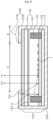
- FIG. 3 illustrates embodiment of the lighting device according to the present invention.
- FIG. 3 The structure of FIG. 3 is different from that of FIG. 2 in that, in the light source module 100 including a printed circuit board 110 having the light source 130 mounted thereon and the light guide member 140, a reflection member 122 (hereinafter, referred to as a ⁇ side reflection member') is further formed at a side portion of the light guide member 140.
- a reflection member 122 hereinafter, referred to as a ⁇ side reflection member'
- the shielding module 200 itself is implemented as a reflection member.
- the side reflection member 122 is disposed using a separate member, so that light can be again reflected at the side portion of the light guide member 140.
- the side reflection member 122 may be implemented integrally with or separately from the reflection member 120 disposed on an upper surface of the printed circuit board 110, using the same material.
- the side reflection member 122 may be implemented using another material.
- the lens member 150 is disposed on the light guide member 140, and both of the lens member 150 and the light guide member 140 are accommodated in the shielding module 200. That is, in the relation of the lens member 150 with the light guide member 140 disposed thereunder, the lens member 150 may be formed in a structure having no spacing part (hereinafter, referred to as a ⁇ non-air-gap structure').
- the diffusion member 160 is adhered closely to the light guide member 140 such that no spacing part is formed between the diffusion member 160 and the light guide member 140.
- a diffusion member is frequently formed on a member such as a light guide plate.
- a spacing part for realizing surface emission is necessarily required to be about 10 mm. Therefore, the light efficiency of the light device is decreased, and it is difficult to design the lighting device.
- the diffusion member 160 is buried in the light guide member 140, and the non-air-gap structure in which a separate spacing part is removed in the shielding module 200 is implemented when a lens member is additionally required or in the structure shown in FIG. 1 , so that the above-described problem can be eliminated. Accordingly, efficient light diffusion can be realized, and light efficiency can be improved.
- the diffusion member 160 functions to uniformly diffuse light emitted by passing through the light guide member 140 throughout the entire surface.
- the diffusion member 160 may be generally formed of acrylic resin, but the present invention is not limited thereto.
- the diffusion member 160 may be made of all materials capable of performing a diffusing function, such as polymethyl methacrylate (PMMA), polystyrene (PS), cyclic olefin polymer (COC), polyethylene terephthalate (PET), and high permeable plastic such as resin.
- PMMA polymethyl methacrylate
- PS polystyrene
- COC cyclic olefin polymer
- PET polyethylene terephthalate
- high permeable plastic such as resin.
- the light source module 100 may basically include the printed circuit board having the light source 130 mounted thereon.
- the printed circuit board 110 refers to a board in which a circuit pattern is formed on a substrate, i.e., PCB.
- the printed circuit board 110 is preferably made of a transparent material. In the case of a conventional lighting device, an FR4 printed circuit board is used, which is opaque. A printed circuit board made of a transparent material, particularly, a transparent PET printed circuit board is used, so that it is possible to provide a transparent lighting device.
- the printed circuit board 110 may be formed as a flexible printed circuit board (FPCB) so as to ensure a certain flexibility.
- FPCB flexible printed circuit board
- the light source 130 constituting the light source module 100 is a part that emits light as one or more light sources are arranged on the printed circuit board 110.
- the light source 130 may be configured as a side view type light emitting diode. That is, a light emitting diode having a structure in which light emitted therefrom does not advance immediately upwards but is emitted toward a side surface thereof may be used as the light source 130. Accordingly, the light source 130 configured as the side view type light emitting diode is disposed in an upright type. Hence, light is diffused and guided in the upper direction, using a resin layer for implementing a light diffusion and reflection function, which will be described below. Thus, the total number of light sources can be decreased, and the entire weight and thickness of the lighting device can be remarkably reduced.
- the light guide member 140 disposed on the printed circuit board 110 is provided above the printed circuit board 110 to diffuse and guide light emitted from the light source 130.
- the light guide member 140 may be not only a conventional light guide plate but also a resin layer substituting for the light guide plate.
- the reflection member 120 is provided between the printed circuit board 110 and the light guide member 140.
- the reflection member 120 is formed on the upper surface of the printed circuit board 110, and has a structure in which the light source 130 is formed to pass therethrough.
- the reflection member 120 is formed of a material having high reflection efficiency to reflect light emitted from the light source to an upper portion at which the diffusion member 150 is located, thereby reducing light loss.
- the reflection member 120 may be formed in a film shape, and include a synthetic resin that spread-contains white pigment so as to implement the natures helping promote the reflection and diffusion of light.
- the white pigment may include titanium dioxide, aluminum oxide, zinc oxide, carbonate, barium sulfate, calcium carbonate, etc.
- the synthetic resin may include polyethylene terephthalate, polyethylene, naphthalate, acrylic resin, polycarbonate, polystyrene, polyolefin, cellulose acetate, weatherproof vinyl chloride, etc.
- the present invention is not limited thereto.
- a reflection pattern 121 may be formed on a surface of the reflection member 120.
- the reflection pattern 121 functions to scatter and disperse incident light such that the light is uniformly transmitted to the diffusion member 160.
- the reflection pattern 121 may be formed by performing printing on the surface of the reflection member 120 using a reflection ink that contains any one of TiO 2 , CaCO 3 , BaSO 4 , Al 2 O 3 , Silicon, PS, and the like, but the present invention is not limited thereto.
- transparent PET may be used as the reflection member 120.
- the reflection pattern 121 is formed in a structure including a plurality of protruding patterns.
- the reflection pattern 121 may be formed in a dot pattern shape, a prism shape, a lenticular shape, a lens shape, or a combination thereof, but the present invention is not limited thereto.
- a section of the reflection pattern 121 may be formed in various shapes such as a triangle shape, a quadrangle shape, a semi-circular shape, a sine wave shape, and the like.
- the reflection pattern 121 may be formed to include the patterns having the same size or different sizes, and the arrangement density of the patterns may also be adjusted. That is, the arrangement density is controlled such that, as each pattern is more distant from the light source 130, the size of the pattern becomes larger, or the distance between the patterns becomes narrower, thereby forming a high pattern density. Thus, the uniformity of light can be ensured by increasing light reflectance when the pattern is distant from the light source 130.
- a resin layer is applied as the light guide member 140.
- the resin layer is coated to be adhered closely to the entire surface of the light source 130, thereby burying the light source 130.
- the resin layer diffuses and guides the light emitted from the light source 130 forward. That is, the resin layer is formed to bury the light source 130, thereby functioning to disperse the light emitted from the light source 130 to a lateral direction. That is, the resin layer can perform the function of the conventional light guide plate.
- the resin layer may be made of a resin material capable of basically diffusing light.
- the resin layer may be made of an ultraviolet curing resin containing an oligomer.
- the resin layer may be made of a resin containing a urethane acrylate oligomer as a main raw material.
- a resin in which the urethane acrylate oligomer corresponding to a synthetic oligomer and a polyacrylic polymer are mixed together may be used.
- the resin layer may further include a monomer corresponding to a low boiling point and diluted type reactive monomer in which isobornyl acrylate (IBOA), hydroxylpropyl acrylate (HPA), 2-hydroxyethyl acrylate (2-HEA), and the like are mixed.
- a photo initiator e.g., 1-hydroxycyclohexyl phenyl-ketone and the like
- an antioxidant e.g., 2-hydroxyethyl acrylate
- the resin layer may be formed using all resin materials capable of performing a light diffusing function, which have been developed and commercialized or can be implemented according to technical development in the future.
- the resin layer further includes a form in which a plurality of beads in which pores (or air gaps) are formed may be mixed and diffused.
- the light beads function to increase a light reflecting and diffusing property. For example, when light emitted from the light source 130 is incident onto the beads inside the resin layer, the light is reflected and transmitted by the pores of the beads. Thus the light is diffused and condensed, and is then emitted upwards. At this time, the reflectance and diffusion coefficient of the light is increased by the beads, so that the uniformity and amount of the emitted light can be increased. As a result, the luminance of the lighting device can be improved.
- a content of the beads may be appropriately adjusted to obtain a desired light diffusing effect. More specifically, the content of the beads may be adjusted within a range of 0.01% to 0.3% compared to a total weight of the resin layer. That is, light emitted from the light source 130 in the lateral direction is diffused and reflected through the resin layer and the beads, thereby advancing upwards.
- the beads may be made of any one selected from among silicon, silica, glass bubble, polymethyl methacrylate (PMMA), urethane, Zn, Zr, Al 2 O 3 , and acryl, and a particle diameter of the beads may be formed in a range of 1 gm to 20 gm.
- PMMA polymethyl methacrylate
- urethane Zn, Zr, Al 2 O 3
- acryl urethane
- a particle diameter of the beads may be formed in a range of 1 gm to 20 gm.
- the present invention is not limited thereto.
- a thickness occupied by the conventional light guide plate can be remarkably reduced, and thus the entire product can be implemented in a slimming structure. Furthermore, it is advantageous in that, thanks to a flexible property, a curved surface can be easily applied, the degree of freedom in a design can be improved, and the lighting device can be also applied to other flexible displays.
- the lighting device can be applied to various lamp devices such as a vehicle lamp, a home lighting device, an industrial lighting device and the like.
- a vehicle lamp when it is applied to the vehicle lamp, it can be also applied to a headlight, a vehicle indoor light, a door scuff, a backlight, and the like.
- the lighting device can be applied to a backlight unit field applied to a liquid crystal display device.
- the lighting device can be also applied to all fields regarding illumination which have been developed and commercialized or may be implemented according to technical development in the future.
Landscapes
- Engineering & Computer Science (AREA)
- Physics & Mathematics (AREA)
- General Engineering & Computer Science (AREA)
- Optics & Photonics (AREA)
- General Physics & Mathematics (AREA)
- Microelectronics & Electronic Packaging (AREA)
- Mechanical Engineering (AREA)
- Planar Illumination Modules (AREA)
Claims (10)
- Un dispositif d'éclairage comprenant :un module (100) formant source de lumière comprenant au moins une source de lumière (130) disposée sur une carte à circuit imprimé (110) et un élément (140) guide de lumière qui noie ladite au moins une source de lumière (130),l'élément (140) guide de lumière comprenant une couche de résine et des billes dans la couche de résine ;un élément de diffusion (160) disposé dans l'élément (140) guide de lumière ; etun module (200) formant écran logeant le module (100) formant source de lumière à l'intérieur de lui,un élément de réflexion (120) disposé sur la carte à circuit imprimé (110) au niveau d'une partie inférieure de l'élément (140) guide de lumière,l'élément de réflexion (120) comprenant en outre un élément de réflexion latéral (122) disposé entre ladite au moins une source de lumière (130) et une surface latérale intérieure du module (200) formant écran,l'élément de diffusion (160) comprenant une forme de feuille ou de film, et l'élément de diffusion (160) étant noyé dans l'élément (140) guide de lumière,l'élément de diffusion (160) étant disposé de façon à être espacé de ladite au moins une source de lumière (130) et à diviser l'élément (140) guide de lumière le long de la direction d'avancement de la lumière (X1, X2) à travers une zone d'ouverture (A) du module (200) formant écran, etl'élément de réflexion latéral (22) étant en contact avec ladite au moins une source de lumière (130) et avec une surface inférieure de l'élément de diffusion (160),le module de protection (200) entourant les surfaces inférieure et latérale du module (100) formant source de lumière, l'élément (140) guide de lumière comprenantun élément guide de lumière (142) inférieur, disposé sur une partie inférieure de l'élément de diffusion (160) et étant directement en contact avec la surface inférieure de l'élément de diffusion (160), etun élément guide de lumière (141) supérieur, disposé sur une partie supérieure de l'élément de diffusion (160) et étant en contact direct avec une surface supérieure de l'élément de diffusion (160),l'élément guide de lumière (142) inférieur et l'élément guide de lumière (141) supérieur étant constitués du même matériau,l'élément guide de lumière (142) inférieur et l'élément de diffusion (160), et l'élément guide de lumière (141) supérieur et l'élément de diffusion (160) étant formés selon une structure sans espace d'air.
- Le dispositif d'éclairage selon la revendication 1, dans lequel l'élément de diffusion (160) est disposé parallèlement à une surface supérieure de l'élément (140) guide de lumière.
- Le dispositif d'éclairage selon l'une quelconque des revendications 1 à 2, dans lequel l'élément (140) guide de lumière est en contact direct avec la source de lumière (130).
- Le dispositif d'éclairage selon l'une quelconque des revendications 1 à 3, dans lequel la zone d'ouverture (A) est prévue dans une direction supérieure de l'élément (140) guide de lumière, et une zone (B) formant écran du module (200) formant écran s'étend depuis la zone d'ouverture (A) et est pourvue d'un espace de logement logeant le module (140) source de lumière.
- Le dispositif d'éclairage selon la revendication 4,
dans lequel le module (200) formant écran comprend :un corps (220) formant écran, qui entoure des surfaces inférieure et latérales du module (140) source de lumière, le corps formant écran ayant la zone d'ouverture formée en ouvrant une zone partielle d'une partie supérieure de celui-ci ; etune partie courbée (210) formée en courbant une extrémité de la partie supérieure du corps de protection vers le centre du module source de lumière. - Le dispositif d'éclairage selon la revendication 5,
dans lequel la surface inférieure de la partie courbée est en contact avec la surface supérieure de l'élément (140) guide de lumière. - Le dispositif d'éclairage selon la revendication 5,
dans lequel une longueur de la partie courbée est formée de façon à être plus longue qu'une distance allant d'une extrémité de l'élément guide de lumière (160) à ladite au moins une source de lumière (130). - Le dispositif d'éclairage selon la revendication 5, comprenant en outre un élément formant lentille (150) disposé entre une surface inférieure du corps formant écran (220) et la surface supérieure de l'élément (140) guide de lumière,
l'élément formant lentille (150) et l'élément guide de lumière (140) étant formés selon une structure sans espace d'air. - Le dispositif d'éclairage selon la revendication 8,
dans lequel la surface inférieure de la partie courbée est en contact direct avec une surface supérieure de l'élément formant lentille (150). - Une lampe de véhicule comprenant le dispositif d'éclairage selon l'une quelconque des revendications 1 à 9.
Applications Claiming Priority (2)
| Application Number | Priority Date | Filing Date | Title |
|---|---|---|---|
| KR1020140143430A KR102305599B1 (ko) | 2014-10-22 | 2014-10-22 | 조명장치 및 이를 포함하는 차량용 램프 |
| PCT/KR2015/011103 WO2016064174A1 (fr) | 2014-10-22 | 2015-10-20 | Appareil d'éclairage et phare de véhicule comprenant ledit appareil |
Publications (3)
| Publication Number | Publication Date |
|---|---|
| EP3211298A1 EP3211298A1 (fr) | 2017-08-30 |
| EP3211298A4 EP3211298A4 (fr) | 2017-11-29 |
| EP3211298B1 true EP3211298B1 (fr) | 2023-08-23 |
Family
ID=55761145
Family Applications (1)
| Application Number | Title | Priority Date | Filing Date |
|---|---|---|---|
| EP15853404.0A Active EP3211298B1 (fr) | 2014-10-22 | 2015-10-20 | Appareil d'éclairage et phare de véhicule comprenant ledit appareil |
Country Status (4)
| Country | Link |
|---|---|
| US (1) | US10300836B2 (fr) |
| EP (1) | EP3211298B1 (fr) |
| KR (1) | KR102305599B1 (fr) |
| WO (1) | WO2016064174A1 (fr) |
Families Citing this family (8)
| Publication number | Priority date | Publication date | Assignee | Title |
|---|---|---|---|---|
| TWI630502B (zh) * | 2016-08-05 | 2018-07-21 | 金佶科技股份有限公司 | 取像裝置 |
| DE102018215988A1 (de) | 2018-09-19 | 2020-03-19 | Volkswagen Aktiengesellschaft | Lichtmodul, insbesondere zur Verwendung in einer Beleuchtungsvorrichtung für ein Kraftfahrzeug |
| CN110118335B (zh) * | 2019-05-30 | 2021-03-09 | 安徽延达智能科技有限公司 | 一种照明灯的反射聚光结构 |
| US11256018B2 (en) | 2019-07-03 | 2022-02-22 | Varroc Lighting Systems, s.r.o | Light assembly including an illuminating utility segment and a visual stimulant segment |
| JP7743412B2 (ja) | 2020-01-23 | 2025-09-24 | エルジー イノテック カンパニー リミテッド | 光学アセンブリおよびこれを有するリアビューミラーアセンブリ |
| KR20220026684A (ko) * | 2020-08-26 | 2022-03-07 | 엘지이노텍 주식회사 | 조명 장치 및 이를 포함하는 램프 |
| KR20220141021A (ko) * | 2021-04-12 | 2022-10-19 | 현대자동차주식회사 | 차량의 램프 구조 |
| DE102022210250B4 (de) * | 2022-09-28 | 2024-04-25 | Magna Exteriors Gmbh | Beleuchtungssystem für ein Außenverkleidungsteil eines Kraftfahrzeugs |
Citations (1)
| Publication number | Priority date | Publication date | Assignee | Title |
|---|---|---|---|---|
| EP2784374A1 (fr) * | 2013-03-25 | 2014-10-01 | Automotive Lighting Italia S.p.A. A Socio Unico | Dispositif d'éclairage et/ou dispositif de signalisation et méthode de fabrication à cela |
Family Cites Families (19)
| Publication number | Priority date | Publication date | Assignee | Title |
|---|---|---|---|---|
| JP4196888B2 (ja) * | 2004-06-25 | 2008-12-17 | セイコーエプソン株式会社 | 電気光学装置及び電子機器 |
| US7534025B2 (en) * | 2006-08-25 | 2009-05-19 | Philips Lumiled Lighting Company, Llc | Thin backlight with flipped light emitting diode |
| JP2010064684A (ja) * | 2008-09-12 | 2010-03-25 | Lecip Corp | 照明装置 |
| CN102483542B (zh) * | 2009-08-27 | 2015-01-21 | Lg电子株式会社 | 背光单元和显示装置 |
| KR20120102614A (ko) | 2009-11-06 | 2012-09-18 | 가부시키가이샤 구라레 | 조명 장치 |
| CN201851960U (zh) | 2010-02-26 | 2011-06-01 | 金芃 | 薄型直下式led背光模组 |
| KR101793275B1 (ko) * | 2011-03-24 | 2017-11-03 | 삼성디스플레이 주식회사 | 백라이트 유닛 및 백라이트 유닛을 포함하는 표시장치 |
| GB201116517D0 (en) | 2011-09-23 | 2011-11-09 | Nanoco Technologies Ltd | Semiconductor nanoparticle based light emitting materials |
| JP5635472B2 (ja) * | 2011-09-27 | 2014-12-03 | 富士フイルム株式会社 | 導光板 |
| WO2013117755A1 (fr) | 2012-02-10 | 2013-08-15 | Tp Vision Holding B.V. | Dispositif de rétro-éclairage |
| US8858025B2 (en) * | 2012-03-07 | 2014-10-14 | Lg Innotek Co., Ltd. | Lighting device |
| KR101977723B1 (ko) * | 2012-06-27 | 2019-05-13 | 엘지이노텍 주식회사 | 조명장치 |
| CN103515514B (zh) | 2012-06-27 | 2017-05-24 | Lg伊诺特有限公司 | 发光器件 |
| JP6184770B2 (ja) | 2012-06-27 | 2017-08-23 | エルジー イノテック カンパニー リミテッド | 照明装置 |
| US9864232B2 (en) | 2012-08-10 | 2018-01-09 | Dolby Laboratories Licensing Corporation | Light directed modulation displays |
| WO2014033686A2 (fr) * | 2012-08-31 | 2014-03-06 | Koninklijke Philips N.V. | Dispositif d'éclairage basé sur guide de lumière ayant des particules de diffusion de lumière |
| KR102047833B1 (ko) * | 2012-12-17 | 2019-11-22 | 엘지이노텍 주식회사 | 조명장치 및 이를 포함하는 차량용 램프 |
| KR102047847B1 (ko) | 2012-12-17 | 2019-11-22 | 엘지이노텍 주식회사 | 조명 장치 |
| KR102125827B1 (ko) | 2013-10-28 | 2020-06-23 | 엘지이노텍 주식회사 | 조명장치 및 이를 포함하는 차량용 램프 |
-
2014
- 2014-10-22 KR KR1020140143430A patent/KR102305599B1/ko active Active
-
2015
- 2015-10-20 WO PCT/KR2015/011103 patent/WO2016064174A1/fr not_active Ceased
- 2015-10-20 EP EP15853404.0A patent/EP3211298B1/fr active Active
- 2015-10-20 US US15/521,251 patent/US10300836B2/en active Active
Patent Citations (1)
| Publication number | Priority date | Publication date | Assignee | Title |
|---|---|---|---|---|
| EP2784374A1 (fr) * | 2013-03-25 | 2014-10-01 | Automotive Lighting Italia S.p.A. A Socio Unico | Dispositif d'éclairage et/ou dispositif de signalisation et méthode de fabrication à cela |
Also Published As
| Publication number | Publication date |
|---|---|
| EP3211298A4 (fr) | 2017-11-29 |
| KR102305599B1 (ko) | 2021-09-28 |
| US10300836B2 (en) | 2019-05-28 |
| KR20160047250A (ko) | 2016-05-02 |
| EP3211298A1 (fr) | 2017-08-30 |
| WO2016064174A1 (fr) | 2016-04-28 |
| US20180326895A1 (en) | 2018-11-15 |
Similar Documents
| Publication | Publication Date | Title |
|---|---|---|
| EP3211298B1 (fr) | Appareil d'éclairage et phare de véhicule comprenant ledit appareil | |
| US10670794B2 (en) | Illuminating device | |
| EP2902694B1 (fr) | Dispositif d'éclairage et lampe de véhicule le comprenant | |
| US9644813B2 (en) | Lighting device | |
| US9970604B2 (en) | Lighting device | |
| KR102047833B1 (ko) | 조명장치 및 이를 포함하는 차량용 램프 | |
| KR20130134971A (ko) | 조명 장치 | |
| KR102005539B1 (ko) | 차량용 면조명 | |
| US11079074B2 (en) | Lighting device and vehicular lamp comprising same | |
| KR102125679B1 (ko) | 조명장치 및 이를 포함하는 차량용 램프 | |
| KR102292690B1 (ko) | 조명장치 및 이를 포함하는 차량용 램프 | |
| KR102047847B1 (ko) | 조명 장치 | |
| KR102461363B1 (ko) | 조명장치 및 이를 포함하는 차량용 램프 | |
| KR20140026801A (ko) | 조명 장치 | |
| KR102092881B1 (ko) | 조명 장치 | |
| KR20130102717A (ko) | 조명 장치 |
Legal Events
| Date | Code | Title | Description |
|---|---|---|---|
| STAA | Information on the status of an ep patent application or granted ep patent |
Free format text: STATUS: THE INTERNATIONAL PUBLICATION HAS BEEN MADE |
|
| PUAI | Public reference made under article 153(3) epc to a published international application that has entered the european phase |
Free format text: ORIGINAL CODE: 0009012 |
|
| STAA | Information on the status of an ep patent application or granted ep patent |
Free format text: STATUS: REQUEST FOR EXAMINATION WAS MADE |
|
| 17P | Request for examination filed |
Effective date: 20170517 |
|
| AK | Designated contracting states |
Kind code of ref document: A1 Designated state(s): AL AT BE BG CH CY CZ DE DK EE ES FI FR GB GR HR HU IE IS IT LI LT LU LV MC MK MT NL NO PL PT RO RS SE SI SK SM TR |
|
| AX | Request for extension of the european patent |
Extension state: BA ME |
|
| A4 | Supplementary search report drawn up and despatched |
Effective date: 20171030 |
|
| RIC1 | Information provided on ipc code assigned before grant |
Ipc: F21S 8/10 20060101ALI20171024BHEP Ipc: F21V 8/00 20060101AFI20171024BHEP Ipc: B60Q 1/00 20060101ALI20171024BHEP |
|
| DAV | Request for validation of the european patent (deleted) | ||
| DAX | Request for extension of the european patent (deleted) | ||
| STAA | Information on the status of an ep patent application or granted ep patent |
Free format text: STATUS: EXAMINATION IS IN PROGRESS |
|
| 17Q | First examination report despatched |
Effective date: 20210408 |
|
| REG | Reference to a national code |
Ref country code: DE Ref legal event code: R079 Free format text: PREVIOUS MAIN CLASS: F21V0008000000 Ipc: F21S0041141000 Ref country code: DE Ref legal event code: R079 Ref document number: 602015085318 Country of ref document: DE Free format text: PREVIOUS MAIN CLASS: F21V0008000000 Ipc: F21S0041141000 |
|
| GRAP | Despatch of communication of intention to grant a patent |
Free format text: ORIGINAL CODE: EPIDOSNIGR1 |
|
| STAA | Information on the status of an ep patent application or granted ep patent |
Free format text: STATUS: GRANT OF PATENT IS INTENDED |
|
| RIC1 | Information provided on ipc code assigned before grant |
Ipc: F21V 8/00 20060101ALI20230227BHEP Ipc: G02B 6/00 20060101ALI20230227BHEP Ipc: F21S 43/40 20180101ALI20230227BHEP Ipc: F21S 43/30 20180101ALI20230227BHEP Ipc: F21S 43/20 20180101ALI20230227BHEP Ipc: F21S 43/249 20180101ALI20230227BHEP Ipc: F21S 43/245 20180101ALI20230227BHEP Ipc: F21S 43/239 20180101ALI20230227BHEP Ipc: F21S 43/14 20180101ALI20230227BHEP Ipc: F21S 41/30 20180101ALI20230227BHEP Ipc: F21S 41/20 20180101ALI20230227BHEP Ipc: F21S 41/24 20180101ALI20230227BHEP Ipc: F21S 41/141 20180101AFI20230227BHEP |
|
| INTG | Intention to grant announced |
Effective date: 20230328 |
|
| GRAS | Grant fee paid |
Free format text: ORIGINAL CODE: EPIDOSNIGR3 |
|
| GRAA | (expected) grant |
Free format text: ORIGINAL CODE: 0009210 |
|
| STAA | Information on the status of an ep patent application or granted ep patent |
Free format text: STATUS: THE PATENT HAS BEEN GRANTED |
|
| AK | Designated contracting states |
Kind code of ref document: B1 Designated state(s): AL AT BE BG CH CY CZ DE DK EE ES FI FR GB GR HR HU IE IS IT LI LT LU LV MC MK MT NL NO PL PT RO RS SE SI SK SM TR |
|
| REG | Reference to a national code |
Ref country code: GB Ref legal event code: FG4D |
|
| REG | Reference to a national code |
Ref country code: CH Ref legal event code: EP |
|
| REG | Reference to a national code |
Ref country code: DE Ref legal event code: R096 Ref document number: 602015085318 Country of ref document: DE |
|
| REG | Reference to a national code |
Ref country code: IE Ref legal event code: FG4D |
|
| REG | Reference to a national code |
Ref country code: NL Ref legal event code: FP |
|
| REG | Reference to a national code |
Ref country code: LT Ref legal event code: MG9D |
|
| REG | Reference to a national code |
Ref country code: AT Ref legal event code: MK05 Ref document number: 1602967 Country of ref document: AT Kind code of ref document: T Effective date: 20230823 |
|
| PG25 | Lapsed in a contracting state [announced via postgrant information from national office to epo] |
Ref country code: GR Free format text: LAPSE BECAUSE OF FAILURE TO SUBMIT A TRANSLATION OF THE DESCRIPTION OR TO PAY THE FEE WITHIN THE PRESCRIBED TIME-LIMIT Effective date: 20231124 |
|
| PG25 | Lapsed in a contracting state [announced via postgrant information from national office to epo] |
Ref country code: IS Free format text: LAPSE BECAUSE OF FAILURE TO SUBMIT A TRANSLATION OF THE DESCRIPTION OR TO PAY THE FEE WITHIN THE PRESCRIBED TIME-LIMIT Effective date: 20231223 |
|
| PG25 | Lapsed in a contracting state [announced via postgrant information from national office to epo] |
Ref country code: SE Free format text: LAPSE BECAUSE OF FAILURE TO SUBMIT A TRANSLATION OF THE DESCRIPTION OR TO PAY THE FEE WITHIN THE PRESCRIBED TIME-LIMIT Effective date: 20230823 Ref country code: RS Free format text: LAPSE BECAUSE OF FAILURE TO SUBMIT A TRANSLATION OF THE DESCRIPTION OR TO PAY THE FEE WITHIN THE PRESCRIBED TIME-LIMIT Effective date: 20230823 Ref country code: PT Free format text: LAPSE BECAUSE OF FAILURE TO SUBMIT A TRANSLATION OF THE DESCRIPTION OR TO PAY THE FEE WITHIN THE PRESCRIBED TIME-LIMIT Effective date: 20231226 Ref country code: NO Free format text: LAPSE BECAUSE OF FAILURE TO SUBMIT A TRANSLATION OF THE DESCRIPTION OR TO PAY THE FEE WITHIN THE PRESCRIBED TIME-LIMIT Effective date: 20231123 Ref country code: LV Free format text: LAPSE BECAUSE OF FAILURE TO SUBMIT A TRANSLATION OF THE DESCRIPTION OR TO PAY THE FEE WITHIN THE PRESCRIBED TIME-LIMIT Effective date: 20230823 Ref country code: LT Free format text: LAPSE BECAUSE OF FAILURE TO SUBMIT A TRANSLATION OF THE DESCRIPTION OR TO PAY THE FEE WITHIN THE PRESCRIBED TIME-LIMIT Effective date: 20230823 Ref country code: IS Free format text: LAPSE BECAUSE OF FAILURE TO SUBMIT A TRANSLATION OF THE DESCRIPTION OR TO PAY THE FEE WITHIN THE PRESCRIBED TIME-LIMIT Effective date: 20231223 Ref country code: HR Free format text: LAPSE BECAUSE OF FAILURE TO SUBMIT A TRANSLATION OF THE DESCRIPTION OR TO PAY THE FEE WITHIN THE PRESCRIBED TIME-LIMIT Effective date: 20230823 Ref country code: GR Free format text: LAPSE BECAUSE OF FAILURE TO SUBMIT A TRANSLATION OF THE DESCRIPTION OR TO PAY THE FEE WITHIN THE PRESCRIBED TIME-LIMIT Effective date: 20231124 Ref country code: FI Free format text: LAPSE BECAUSE OF FAILURE TO SUBMIT A TRANSLATION OF THE DESCRIPTION OR TO PAY THE FEE WITHIN THE PRESCRIBED TIME-LIMIT Effective date: 20230823 Ref country code: AT Free format text: LAPSE BECAUSE OF FAILURE TO SUBMIT A TRANSLATION OF THE DESCRIPTION OR TO PAY THE FEE WITHIN THE PRESCRIBED TIME-LIMIT Effective date: 20230823 |
|
| PG25 | Lapsed in a contracting state [announced via postgrant information from national office to epo] |
Ref country code: PL Free format text: LAPSE BECAUSE OF FAILURE TO SUBMIT A TRANSLATION OF THE DESCRIPTION OR TO PAY THE FEE WITHIN THE PRESCRIBED TIME-LIMIT Effective date: 20230823 |
|
| PG25 | Lapsed in a contracting state [announced via postgrant information from national office to epo] |
Ref country code: ES Free format text: LAPSE BECAUSE OF FAILURE TO SUBMIT A TRANSLATION OF THE DESCRIPTION OR TO PAY THE FEE WITHIN THE PRESCRIBED TIME-LIMIT Effective date: 20230823 |
|
| PG25 | Lapsed in a contracting state [announced via postgrant information from national office to epo] |
Ref country code: SM Free format text: LAPSE BECAUSE OF FAILURE TO SUBMIT A TRANSLATION OF THE DESCRIPTION OR TO PAY THE FEE WITHIN THE PRESCRIBED TIME-LIMIT Effective date: 20230823 Ref country code: RO Free format text: LAPSE BECAUSE OF FAILURE TO SUBMIT A TRANSLATION OF THE DESCRIPTION OR TO PAY THE FEE WITHIN THE PRESCRIBED TIME-LIMIT Effective date: 20230823 Ref country code: ES Free format text: LAPSE BECAUSE OF FAILURE TO SUBMIT A TRANSLATION OF THE DESCRIPTION OR TO PAY THE FEE WITHIN THE PRESCRIBED TIME-LIMIT Effective date: 20230823 Ref country code: EE Free format text: LAPSE BECAUSE OF FAILURE TO SUBMIT A TRANSLATION OF THE DESCRIPTION OR TO PAY THE FEE WITHIN THE PRESCRIBED TIME-LIMIT Effective date: 20230823 Ref country code: DK Free format text: LAPSE BECAUSE OF FAILURE TO SUBMIT A TRANSLATION OF THE DESCRIPTION OR TO PAY THE FEE WITHIN THE PRESCRIBED TIME-LIMIT Effective date: 20230823 Ref country code: CZ Free format text: LAPSE BECAUSE OF FAILURE TO SUBMIT A TRANSLATION OF THE DESCRIPTION OR TO PAY THE FEE WITHIN THE PRESCRIBED TIME-LIMIT Effective date: 20230823 Ref country code: SK Free format text: LAPSE BECAUSE OF FAILURE TO SUBMIT A TRANSLATION OF THE DESCRIPTION OR TO PAY THE FEE WITHIN THE PRESCRIBED TIME-LIMIT Effective date: 20230823 |
|
| REG | Reference to a national code |
Ref country code: DE Ref legal event code: R097 Ref document number: 602015085318 Country of ref document: DE |
|
| PG25 | Lapsed in a contracting state [announced via postgrant information from national office to epo] |
Ref country code: IT Free format text: LAPSE BECAUSE OF FAILURE TO SUBMIT A TRANSLATION OF THE DESCRIPTION OR TO PAY THE FEE WITHIN THE PRESCRIBED TIME-LIMIT Effective date: 20230823 Ref country code: MC Free format text: LAPSE BECAUSE OF FAILURE TO SUBMIT A TRANSLATION OF THE DESCRIPTION OR TO PAY THE FEE WITHIN THE PRESCRIBED TIME-LIMIT Effective date: 20230823 |
|
| REG | Reference to a national code |
Ref country code: CH Ref legal event code: PL |
|
| REG | Reference to a national code |
Ref country code: BE Ref legal event code: MM Effective date: 20231031 |
|
| PG25 | Lapsed in a contracting state [announced via postgrant information from national office to epo] |
Ref country code: LU Free format text: LAPSE BECAUSE OF NON-PAYMENT OF DUE FEES Effective date: 20231020 |
|
| PLBE | No opposition filed within time limit |
Free format text: ORIGINAL CODE: 0009261 |
|
| STAA | Information on the status of an ep patent application or granted ep patent |
Free format text: STATUS: NO OPPOSITION FILED WITHIN TIME LIMIT |
|
| PG25 | Lapsed in a contracting state [announced via postgrant information from national office to epo] |
Ref country code: LU Free format text: LAPSE BECAUSE OF NON-PAYMENT OF DUE FEES Effective date: 20231020 |
|
| PG25 | Lapsed in a contracting state [announced via postgrant information from national office to epo] |
Ref country code: CH Free format text: LAPSE BECAUSE OF NON-PAYMENT OF DUE FEES Effective date: 20231031 |
|
| GBPC | Gb: european patent ceased through non-payment of renewal fee |
Effective date: 20231123 |
|
| 26N | No opposition filed |
Effective date: 20240524 |
|
| PG25 | Lapsed in a contracting state [announced via postgrant information from national office to epo] |
Ref country code: FR Free format text: LAPSE BECAUSE OF NON-PAYMENT OF DUE FEES Effective date: 20231023 Ref country code: CH Free format text: LAPSE BECAUSE OF NON-PAYMENT OF DUE FEES Effective date: 20231031 Ref country code: SI Free format text: LAPSE BECAUSE OF FAILURE TO SUBMIT A TRANSLATION OF THE DESCRIPTION OR TO PAY THE FEE WITHIN THE PRESCRIBED TIME-LIMIT Effective date: 20230823 |
|
| PG25 | Lapsed in a contracting state [announced via postgrant information from national office to epo] |
Ref country code: BE Free format text: LAPSE BECAUSE OF NON-PAYMENT OF DUE FEES Effective date: 20231031 |
|
| PG25 | Lapsed in a contracting state [announced via postgrant information from national office to epo] |
Ref country code: IE Free format text: LAPSE BECAUSE OF NON-PAYMENT OF DUE FEES Effective date: 20231020 |
|
| PG25 | Lapsed in a contracting state [announced via postgrant information from national office to epo] |
Ref country code: GB Free format text: LAPSE BECAUSE OF NON-PAYMENT OF DUE FEES Effective date: 20231123 |
|
| PG25 | Lapsed in a contracting state [announced via postgrant information from national office to epo] |
Ref country code: IE Free format text: LAPSE BECAUSE OF NON-PAYMENT OF DUE FEES Effective date: 20231020 Ref country code: GB Free format text: LAPSE BECAUSE OF NON-PAYMENT OF DUE FEES Effective date: 20231123 |
|
| PG25 | Lapsed in a contracting state [announced via postgrant information from national office to epo] |
Ref country code: BG Free format text: LAPSE BECAUSE OF FAILURE TO SUBMIT A TRANSLATION OF THE DESCRIPTION OR TO PAY THE FEE WITHIN THE PRESCRIBED TIME-LIMIT Effective date: 20230823 |
|
| PG25 | Lapsed in a contracting state [announced via postgrant information from national office to epo] |
Ref country code: BG Free format text: LAPSE BECAUSE OF FAILURE TO SUBMIT A TRANSLATION OF THE DESCRIPTION OR TO PAY THE FEE WITHIN THE PRESCRIBED TIME-LIMIT Effective date: 20230823 |
|
| PG25 | Lapsed in a contracting state [announced via postgrant information from national office to epo] |
Ref country code: CY Free format text: LAPSE BECAUSE OF FAILURE TO SUBMIT A TRANSLATION OF THE DESCRIPTION OR TO PAY THE FEE WITHIN THE PRESCRIBED TIME-LIMIT; INVALID AB INITIO Effective date: 20151020 |
|
| PG25 | Lapsed in a contracting state [announced via postgrant information from national office to epo] |
Ref country code: HU Free format text: LAPSE BECAUSE OF FAILURE TO SUBMIT A TRANSLATION OF THE DESCRIPTION OR TO PAY THE FEE WITHIN THE PRESCRIBED TIME-LIMIT; INVALID AB INITIO Effective date: 20151020 |
|
| PGFP | Annual fee paid to national office [announced via postgrant information from national office to epo] |
Ref country code: NL Payment date: 20250922 Year of fee payment: 11 |
|
| PG25 | Lapsed in a contracting state [announced via postgrant information from national office to epo] |
Ref country code: TR Free format text: LAPSE BECAUSE OF FAILURE TO SUBMIT A TRANSLATION OF THE DESCRIPTION OR TO PAY THE FEE WITHIN THE PRESCRIBED TIME-LIMIT Effective date: 20230823 |
|
| PGFP | Annual fee paid to national office [announced via postgrant information from national office to epo] |
Ref country code: DE Payment date: 20250922 Year of fee payment: 11 |