EP3211326A1 - Dunstabzugshaube - Google Patents
Dunstabzugshaube Download PDFInfo
- Publication number
- EP3211326A1 EP3211326A1 EP17152810.2A EP17152810A EP3211326A1 EP 3211326 A1 EP3211326 A1 EP 3211326A1 EP 17152810 A EP17152810 A EP 17152810A EP 3211326 A1 EP3211326 A1 EP 3211326A1
- Authority
- EP
- European Patent Office
- Prior art keywords
- support
- cable
- extractor hood
- conductor
- support member
- Prior art date
- Legal status (The legal status is an assumption and is not a legal conclusion. Google has not performed a legal analysis and makes no representation as to the accuracy of the status listed.)
- Granted
Links
Images


Classifications
-
- F—MECHANICAL ENGINEERING; LIGHTING; HEATING; WEAPONS; BLASTING
- F24—HEATING; RANGES; VENTILATING
- F24C—DOMESTIC STOVES OR RANGES ; DETAILS OF DOMESTIC STOVES OR RANGES, OF GENERAL APPLICATION
- F24C15/00—Details
- F24C15/20—Removing cooking fumes
-
- F—MECHANICAL ENGINEERING; LIGHTING; HEATING; WEAPONS; BLASTING
- F24—HEATING; RANGES; VENTILATING
- F24C—DOMESTIC STOVES OR RANGES ; DETAILS OF DOMESTIC STOVES OR RANGES, OF GENERAL APPLICATION
- F24C15/00—Details
- F24C15/20—Removing cooking fumes
- F24C15/2071—Removing cooking fumes mounting of cooking hood
-
- H—ELECTRICITY
- H01—ELECTRIC ELEMENTS
- H01B—CABLES; CONDUCTORS; INSULATORS; SELECTION OF MATERIALS FOR THEIR CONDUCTIVE, INSULATING OR DIELECTRIC PROPERTIES
- H01B7/00—Insulated conductors or cables characterised by their form
- H01B7/17—Protection against damage caused by external factors, e.g. sheaths or armouring
- H01B7/18—Protection against damage caused by wear, mechanical force or pressure; Sheaths; Armouring
- H01B7/182—Protection against damage caused by wear, mechanical force or pressure; Sheaths; Armouring comprising synthetic filaments
- H01B7/1825—Protection against damage caused by wear, mechanical force or pressure; Sheaths; Armouring comprising synthetic filaments forming part of a high tensile strength core
Definitions
- the invention relates to an extractor hood with a support cable.
- a three-core supply line also called a fifth cable, can be used in addition to the ceiling attachment.
- the object of the invention is to provide an improved extractor hood, in particular an improved supporting cable for an extractor hood.
- the invention has the advantage that an electrical line and a support member for receiving a mechanical load in a single rope can be combined with each other, so that the power supply via this cable takes place.
- This has the advantage that can be dispensed with a separate, possibly visually unattractive or disturbing power cord for powering the hood. For example, the electrical supply of the hood over three or four or more such ropes can be done.
- a connection part may, for example, be understood as a connection block having at least one connection for connecting the shield part to a power supply.
- the support member may be mechanically fastened to the connection part.
- Under a conductor member may be an electrical line, such as a wire, to be understood.
- Under a support member an elastic rope or a rod can be understood.
- the support member may be a wire or a wire mesh.
- the conductor member and the support member may be realized as separate members of the support cable. As a result, a simple production of the supporting cable is made possible.
- the conductor member and the support member may extend coaxially or parallel to one another.
- the carrying cable can be realized with the smallest possible cross-section with high stability.
- a carrying cable comprises a single support member and a single conductor member.
- This makes it possible to provide support cables with a small circumference, which improves the aesthetic requirements of a cable suspension.
- the invention also includes the possibility that a support cable comprises a plurality of support members and / or a plurality, in particular electrically separate, conductor members.
- the hood can be connected to several independently switchable outer conductors and / or neutral conductors. It is thus possible, for example, to switch a lighting component of the extractor hood separately from the extractor hood.
- the conductor member is encased at least in sections with at least one electrically insulating insulating layer.
- the conductor member can be electrically isolated.
- the conductor member may be at least partially marked in color. This allows easy identification of the conductor member.
- the conductor member or the support member may be at least partially sheathed with at least one protective layer for protection against mechanical stresses.
- both members may be sheathed with the protective layer.
- conductor member and support member of a support rope are arranged together in a surrounding shell, wherein the shell is a protective layer for protection against mechanical stress and / or an electrically insulating insulating layer. It is also advantageous if the conductor member and, additionally or alternatively, the support member as a wire, wire mesh, braided or beaten rope or as a Combination of at least two of the structures mentioned are realized. As a result, the carrying rope can be made as stable as possible.
- the conductor member and the support member may be guided apart at at least one end of the support cable.
- the conductor member and the support member may be free-standing at at least one end of the support cable. Thereby, the conductor member and the support member can be easily connected to different locations of the screen member or the connector part.
- the shield member may include at least one shield terminal for connecting the conductor member, a shield attachment site for attaching the support member, and a shield opening for passing the support rope when connecting the conductor member to the shield terminal and / or attaching the support member to the shield attachment site.
- the extractor hood may have at least one further carrying cable.
- the further support cable may have a further conductor member for electrically conductive connection of the shield member to the connector part and a further support member for suspending the umbrella part on the ceiling and / or the connector part.
- the further support member may be configured to receive at least a major portion of a tensile force exerted on the further support cable in the suspended state of the umbrella part.
- the extractor hood can have a total of at least three such support cables.
- the screen part can thereby be connected via separate carrying cables with different connections in the connecting part, for example a neutral conductor, outer conductor or protective conductor connection.
- the extractor hood preferably comprises three or more carrying cables.
- the extractor hood preferably comprises three or more carrying cables.
- four or more support cables with a conductor member and a support member and only three required, electrically separated conductor members is an improvement of Transmission security of electrical energy possible. This is achieved, in particular, by the fact that the conductor links of at least two different carrying cables are preferably connected to the protective conductor connection.
- the conductor member and the support member are arranged together in a surrounding shell in at least one support cable, wherein the shell is a protective layer for protection against mechanical stress and / or an electrically insulating insulating layer.
- FIG. 1 shows a schematic representation of an extractor hood 100 according to an embodiment.
- the extractor hood 100 comprises a screen part 102 and a connection part 104.
- the lower screen part 102 is fastened to the upper connection part 104 by means of a carrying cable 106.
- the connection part 104 can be mechanically connected to a ceiling and serves for the electrical connection of the extractor hood 100 to a mains voltage.
- the connection part 104 is realized as a ceiling connection box for direct connection by means of a fixed connection or mains cable.
- the extractor hood 100 in addition to the carrying cable 106 optionally has two further carrying cables 108 which each function as a connecting cable for suspending the umbrella part 102 on the connecting part 104.
- the screen portion 102 includes, for example, a whole ventilation technology, including grease filter, odor filter, fan, motor, control and controls.
- the cooker hood 100 is realized with four or more such suspension cables.
- a three-wire line for example, is divided into three individual lines by means of the three support cables 106, 108.
- the supply of the shield part 102 can be divided into four ropes for optical reasons.
- the support cables 106, 108 each include a pull cable for carrying a mechanical load and an electrically conductive wire.
- the three suspension ropes can each be designed as a rigid rope in the classical sense or as a braid.
- the main part, d. H. the traction cable is attached to both the connection part 104 and the screen part 102.
- the electrically conductive wires of the three suspension cables are connected in the ceiling connection for L, N and PE, d.
- the wires are isolated over the three support cables and are brought together in the screen part 102 again. At least one wire can be marked in color.
- the conductor assigned to the protective conductor PE is preferably color-coded, for example green-yellow.
- the subject matter of the invention also includes the possibility of identifying further cores, in particular also the cores associated with the outer conductor and / or with the neutral conductor. Here, it has proven to be particularly advantageous to use different colored labels for the different conductors assigned wires.
- Lamps are known in which electrical conductors are used as suspension cables.
- the big difference to an extractor hood lies in the approval or approval of a, especially outside the housing arranged power supply line.
- the requirements for a mains supply for domestic appliances are described in the valid standard IEC / EN60335-1.
- a colored marking of the protective conductor is required. This is not the case for leads for lamps, some of which do not transmit mains voltage.
- a live cable should not be loaded with mechanical tension in household appliances.
- a distinction should be made between a conductive part and a supporting part of the rope.
- a fourth support cable this can be realized, for example, as a protective conductor.
- a protective conductor connection can be improved since the protective conductor is then connected to the shielding part 102 via two paths.
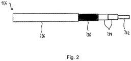
- FIG. 2 shows a schematic representation of a support cable 106 according to an embodiment, for example, a support cable, as described above with reference to FIG. 1 is described.
- the support cable 106 is realized as a connecting string of a mechanical load bearing support member 200 and an electrical energy transmitting conductor member 202. According to this embodiment, the support cable 106 is constructed coaxially.
- the current-carrying conductor member 202 is encased with two electrically insulating insulating layers 204.
- a wire mesh as a support member 200, which in turn is coated with a protective layer 206 in the form of a protective insulation.
- the conductor member 202 may be sheathed with only one insulating layer 204.
- An outer of the two insulating layers 204 can also serve for example for mechanical protection.
- the protective layer 206 which is realized here as an outer jacket of the carrying cable 106, is optional. By means of the protective layer 206, for example, a risk of injury can be reduced.
- the support member 200 may be realized as a core of the support cable 106, wherein the conductor member 202 may be realized as a cladding braid surrounding the support member 200.
- the support member 200 may be provided with insulation.
- the conductor member 202 in the form of the sheath braid may for example be sheathed with two electrically insulating insulating layers.
- FIG. 3 shows a schematic representation of a cross section through a support cable 106 according to an embodiment.
- the support cable 106 may be a preceding with reference to FIG. 1 act described rope.
- the supporting cable 106 is constructed in parallel according to this embodiment.
- parallel to the conductor member 202 a realized example of a plurality of wires pull rope is introduced as a support member 200.
- Analogous to FIG. 2 is the conductor member 202 with the two insulating layers 204 sheathed.
- the protective layer 206 extends as the outermost layer of the support cable 106th
- the support member 200 and the conductor member 202 may be realized as a single or multiple wire or as a braided or beaten rope.
- the support member 200 may also be realized as a rigid body, for example as a rod.
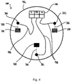
- FIG. 4 shows a schematic representation of an extractor hood 100 according to an embodiment in plan view.
- the extractor hood 100 essentially corresponds to the previous one with reference to FIG FIG. 1 described extractor hood, with the difference that the screen portion 102 is not rectangular, but circular.
- Shown is a possible connection diagram in the connection part 102 and in the shield part 104.
- the connection part 104 has an outer conductor connection L, a protective conductor connection PE and a neutral connection N.
- the outer conductor connection L is electrically conductively connected to control electronics in the shielding part 102 via the conductor member of the support cable 106.
- the protective earth terminal PE and the neutral terminal N are each electrically conductively connected via a conductor member of the two other supporting cables 108 to the control electronics.
- the screen part 102 is realized with a screen opening 300, through which the carrying cable 106 is passed.
- the two other support cables 108 are each through another screen opening 302 is guided in the screen part 102.
- the respective conductor and support members of the three support cables 106, 108 are guided apart both in the connection part 104 and in the screen part 102.
- one end of the support member 200 of the support cable 106 is mechanically connected to the screen portion 102 at a screen attachment point 304.
- the two further support cables 108 have analogous to the support cable 106 in each case a further support member 306, whose end is mechanically connected to a respective screen attachment point 308 on the screen portion 102.
- the respective conductor members of the three support cables 106, 108 are electrically connected to a power line or the control electronics.
Landscapes
- Engineering & Computer Science (AREA)
- Chemical & Material Sciences (AREA)
- Combustion & Propulsion (AREA)
- Mechanical Engineering (AREA)
- General Engineering & Computer Science (AREA)
- Installation Of Indoor Wiring (AREA)
Abstract
Description
- Die Erfindung betrifft eine Dunstabzugshaube mit einem Tragseil.
- Zum Transferieren elektrischer Energie von einer an einer Decke befindlichen Anschlussdose zu einer freihängenden Dunsthaube kann zusätzlich zur Deckenbefestigung eine dreiadrige Zuleitung, auch fünftes Seil genannt, verwendet werden.
- Der Erfindung stellt sich die Aufgabe, eine verbesserte Dunstabzugshaube, insbesondere ein verbessertes Tragseil für eine Dunstabzugshaube zu schaffen.
- Erfindungsgemäß wird diese Aufgabe durch eine Dunstabzugshaube mit den Merkmalen des Hauptanspruchs gelöst. Vorteilhafte Ausgestaltungen und Weiterbildungen der Erfindung ergeben sich aus den nachfolgenden Unteransprüchen.
- Die Erfindung bietet den Vorteil, dass eine elektrische Leitung und ein Tragglied zum Aufnehmen einer mechanischen Last in einem einzigen Seil miteinander kombiniert werden können, sodass die Energiezufuhr über dieses Seil erfolgt. Dies hat den Vorteil, dass auf eine separate, unter Umständen optisch unattraktive oder störende Netzanschlussleitung zur Stromversorgung der Dunstabzugshaube verzichtet werden kann. Beispielsweise kann die elektrische Versorgung der Dunstabzugshaube über drei oder vier oder mehr solcher Seile erfolgen.
- Es wird ein Tragseil für eine Dunstabzugshaube vorgestellt, wobei die Dunstabzugshaube einen Schirmteil und einen an einer Decke befestigbaren Anschlussteil zum Anschließen der Dunstabzugshaube an eine Stromversorgung umfasst, wobei das Tragseil folgende Merkmale aufweist:
- ein Leiterglied zum elektrisch leitfähigen Verbinden des Schirmteils mit dem Anschlussteil; und
- ein Tragglied zum Aufhängen des Schirmteils an der Decke und/oder dem Anschlussteil, wobei das Tragglied ausgebildet ist, um im aufgehängten Zustand des Schirmteils zumindest einen Hauptanteil einer auf das Tragseil ausgeübten Zugkraft aufzunehmen.
- Unter einem Schirmteil kann beispielsweise eine freihängende Inselhaube verstanden werden. Unter einem Anschlussteil kann beispielsweise ein Anschlussblock mit zumindest einem Anschluss zum Anschließen des Schirmteils an ein Stromnetz verstanden werden. Beispielsweise kann das Tragglied an dem Anschlussteil mechanisch befestigbar sein. Unter einem Leiterglied kann eine elektrische Leitung, beispielsweise eine Ader, verstanden werden. Unter einem Tragglied kann ein elastisches Seil oder ein Stab verstanden werden. Beispielsweise kann es sich bei dem Tragglied um einen Draht oder ein Drahtgeflecht handeln.
- Gemäß einer Ausführungsform können das Leiterglied und das Tragglied als separate Glieder des Tragseils realisiert sein. Dadurch wird eine einfache Herstellung des Tragseils ermöglicht.
- Gemäß einer weiteren Ausführungsform können das Leiterglied und das Tragglied koaxial oder parallel zueinander verlaufen. Dadurch kann das Tragseil mit einem möglichst geringen Querschnitt bei hoher Stabilität realisiert werden.
- Als günstig erwiesen hat es sich, dass ein Tragseil ein einziges Tragglied und ein einziges Leiterglied umfasst. Hierdurch ist es möglich Tragseile mit geringem Umfang bereitzustellen, was den ästhetischen Anspruch an eine Seilaufhängung verbessert. Dennoch schließt die Erfindung auch die Möglichkeit ein, dass ein Tragseil mehrere Tragglieder und/oder mehrere, insbesondere elektrisch voneinander getrennte, Leiterglieder umfasst. So kann die Dunstabzugshaube an mehreren unabhängig schaltbaren Außenleitern und/oder Neutralleitern angeschlossen werden. So ist es beispielsweise möglich, eine Beleuchtungskomponente der Dunstabzugshaube separat von der Dunstabzugshaube zu schalten.
- Es ist vorteilhaft, wenn das Leiterglied zumindest abschnittsweise mit zumindest einer elektrisch isolierenden Isolierschicht ummantelt ist. Dadurch kann das Leiterglied elektrisch isoliert werden. Zusätzlich oder alternativ kann das Leiterglied zumindest abschnittsweise farblich gekennzeichnet sein. Dadurch wird eine einfache Identifizierung des Leiterglieds ermöglicht.
- Des Weiteren kann das Leiterglied oder das Tragglied zumindest abschnittsweise mit zumindest einer Schutzschicht zum Schutz vor mechanischen Belastungen ummantelt sein. Alternativ können beide Glieder mit der Schutzschicht ummantelt sein. Dadurch kann das Leiterglied oder das Tragglied wirksam vor Beschädigungen geschützt werden.
- Gemäß einer bevorzugten Ausführungsform sind Leiterglied und Tragglied eines Tragseils gemeinsam in einer sie umgebenden Hülle angeordnet, wobei die Hülle eine Schutzschicht zum Schutz vor mechanischen Belastungen und/oder eine elektrisch isolierende Isolierschicht ist. Es ist ferner von Vorteil, wenn das Leiterglied und, zusätzlich oder alternativ, das Tragglied als Draht, Drahtgeflecht, geflochtenes oder geschlagenes Seil oder als eine Kombination aus zumindest zwei der genannten Strukturen realisiert sind. Dadurch kann das Tragseil möglichst stabil ausgeführt werden.
- Gemäß einer weiteren Ausführungsform können das Leiterglied und das Tragglied an zumindest einem Ende des Tragseils auseinandergeführt sein. Beispielsweise können das Leiterglied und das Tragglied an zumindest einem Ende des Tragseils freistehend sein. Dadurch können das Leiterglied und das Tragglied sehr einfach mit unterschiedlichen Stellen des Schirmteils oder des Anschlussteils verbunden werden.
- Der hier vorgestellte Ansatz schafft zudem eine Dunstabzugshaube mit folgenden Merkmalen:
- einem Schirmteil;
- einem an einer Decke befestigbaren Anschlussteil zum Anschließen der Dunstabzugshaube an eine Stromversorgung; und
- zumindest einem Tragseil gemäß einer der vorstehenden Ausführungsformen.
- Gemäß einer Ausführungsform kann der Schirmteil zumindest einen Schirmanschluss zum Anschließen des Leiterglieds, eine Schirmbefestigungsstelle zum Befestigen des Tragglieds und eine Schirmöffnung zum Hindurchführen des Tragseils beim Anschließen des Leiterglieds an dem Schirmanschluss und/oder beim Befestigen des Tragglieds an der Schirmbefestigungsstelle aufweisen. Durch diese Ausführungsform wird eine einfache, stabile und optisch unauffällige Befestigung des Tragseils am Schirmteil ermöglicht.
- Die Dunstabzugshaube kann gemäß einer weiteren Ausführungsform zumindest ein weiteres Tragseil aufweisen. Das weitere Tragseil kann ein weiteres Leiterglied zum elektrisch leitfähigen Verbinden des Schirmteils mit dem Anschlussteil und ein weiteres Tragglied zum Aufhängen des Schirmteils an der Decke und/oder dem Anschlussteil aufweisen. Das weitere Tragglied kann ausgebildet sein, um im aufgehängten Zustand des Schirmteils zumindest einen Hauptanteil einer auf das weitere Tragseil ausgeübten Zugkraft aufzunehmen. Beispielsweise kann die Dunstabzugshaube insgesamt zumindest drei solcher Tragseile aufweisen. Dadurch wird zum einen eine stabile Befestigung des Schirmteils ermöglicht; zum anderen kann das Schirmteil dadurch über separate Tragseile mit unterschiedlichen Anschlüssen im Anschlussteil, etwa einem Neutralleiter-, Außenleiter- oder Schutzleiteranschluss, verbunden werden.
- Die Dunstabzugshaube umfasst vorzugsweise drei oder mehr Tragseile. Bei der Verwendung von vier oder mehr Tragseilen mit einem Leiterglied und einem Tragglied und nur drei erforderlichen, elektrisch voneinander getrennten Leitergliedern ist eine Verbesserung der Übertragungssicherheit der elektrischen Energie möglich. Dies wird insbesondere dadurch erreicht, dass das vorzugsweise mit dem Schutzleiteranschluss die Leiterglieder von wenigstens zwei unterschiedlichen Tragseilen verbunden sind. Es ist darüber hinaus auch möglich den Außenleiteranschluss und/oder den Neutralleiteranschluss mit den Leitergliedern mehrerer unterschiedlicher Tragseile zu verbinden. Letzteres insbesondere um eine hohe Stromstärke über Leiterglieder mit geringem Querschnitt zu übertragen.
- Gemäß einer bevorzugten Ausführungsform sind bei wenigstens einem Tragseil das Leiterglied und das Tragglied gemeinsam in einer sie umgebenden Hülle angeordnet sind, wobei die Hülle eine Schutzschicht zum Schutz vor mechanischen Belastungen und/oder eine elektrisch isolierende Isolierschicht ist.
- Ein Ausführungsbeispiel der Erfindung ist in den Zeichnungen rein schematisch dargestellt und wird nachfolgend näher beschrieben. Es zeigt
- Figur 1
- eine schematische Darstellung einer Dunstabzugshaube gemäß einem Ausführungsbeispiel;
- Figur 2
- eine schematische Darstellung eines Tragseils gemäß einem Ausführungsbeispiel;
- Figur 3
- eine schematische Darstellung eines Querschnitts durch ein Tragseil gemäß einem Ausführungsbeispiel; und
- Figur 4
- eine schematische Darstellung einer Dunstabzugshaube gemäß einem Ausführungsbeispiel in der Draufsicht.
-
Figur 1 zeigt eine schematische Darstellung einer Dunstabzugshaube 100 gemäß einem Ausführungsbeispiel. Die Dunstabzugshaube 100 umfasst einen Schirmteil 102 und einen Anschlussteil 104. Der untere Schirmteil 102 ist mittels eines Tragseils 106 an dem oberen Anschlussteil 104 befestigt. Der Anschlussteil 104 ist mechanisch mit einer Raumdecke verbindbar und dient der elektrischen Anbindung der Dunstabzugshaube 100 an eine Netzspannung. Beispielsweise ist der Anschlussteil 104 als Deckenanschlusskasten zum direkten Anschließen per Festanschluss oder Netzkabel realisiert. - Gemäß diesem Ausführungsbeispiel weist die Dunstabzugshaube 100 zusätzlich zum Tragseil 106 optional zwei weitere Tragseile 108 auf, die je als Verbindungsseil zum Aufhängen des Schirmteils 102 an dem Anschlussteil 104 fungieren. Der Schirmteil 102 umfasst beispielsweise eine gesamte Lüftungstechnik, einschließlich Fettfilter, Geruchsfilter, Lüfter, Motor, Steuerung und Bedienelemente. Alternativ ist die Dunstabzugshaube 100 mit vier oder mehr solcher Tragseile realisiert.
- Um eine elektrisch leitfähige Verbindung zwischen dem Schirmteil 102 und dem Anschlussteil 104 herzustellen, wird beispielsweise eine dreiadrige Leitung mittels der drei Tragseile 106, 108 auf drei einzelne Leitungen aufgeteilt. Alternativ kann die Versorgung des Schirmteils 102 aus optischen Gründen auf vier Seile aufgeteilt werden. Die Tragseile 106, 108 umfassen jeweils ein Zugseil zum Tragen einer mechanischen Last und eine elektrisch leitfähige Ader. Die drei Tragseile können je als starres Seil im klassischen Sinn oder als Geflecht ausgeführt sein. Der tragende Teil, d. h. das Zugseil, ist sowohl am Anschlussteil 104 als auch im Schirmteil 102 befestigt. Die elektrisch leitfähigen Adern der drei Tragseile sind im Deckenanschluss für L, N und PE angeschlossen, d. h., die Adern sind über die drei Tragseile vereinzelt und werden im Schirmteil 102 wieder zusammengeführt. Zumindest eine Ader kann farblich gekennzeichnet sein. Vorzugsweise ist die dem Schutzleiter PE zugeordnete Ader farblich gekennzeichnet beispielsweise grün-gelb. Der Gegenstand der Erfindung schließt auch die Möglichkeit ein weitere Adern, insbesondere auch die dem Außenleiter und/oder mit dem Neutralleiter zugeordneten Adern farblich zu kennzeichnen. Hier hat es sich als besonders vorteilhaft erwiesen, dass für die unterschiedlichen Leitern zugewiesenen Adern verschiedene farbliche Kennzeichnungen zu verwenden.
- Es sind Lampen bekannt, bei denen elektrische Leiter als Tragseile verwendet werden. Der große Unterschied zu einer Dunstabzugshaube liegt in der Zulassung oder Approbation einer, insbesondere außerhalb des Gehäuses angeordneten Netzzuleitung. Die Anforderungen an eine Netzzuleitung für Hausgeräte sind in der gültigen Norm IEC/EN60335-1 beschrieben. Unter anderem ist eine farbliche Kennzeichnung des Schutzleiters erforderlich. Dies ist bei Zuleitungen für Lampen, die zum Teil auch keine Netzspannung übertragen, nicht gegeben.
- Des Weiteren sollte bei Hausgeräten eine spannungsführende Leitung nicht auf mechanischen Zug belastet werden. Somit sollte zwischen einem leitenden Teil und einem tragenden Teil des Seils unterschieden werden.
- Sollte es aus Design- oder konstruktiven Gründen erforderlich sein, ein viertes Tragseil einzusetzen, so kann dieses beispielsweise als Schutzleiter realisiert sein. Dadurch kann eine Schutzleiteranbindung verbessert werden, da der Schutzleiter dann über zwei Wege mit dem Schirmteil 102 verbunden ist.
-
Figur 2 zeigt eine schematische Darstellung eines Tragseils 106 gemäß einem Ausführungsbeispiel, beispielsweise eines Tragseils, wie es vorangehend anhand vonFigur 1 beschrieben ist. Das Tragseil 106 ist als ein Verbindungsstrang aus einem eine mechanische Last tragenden Tragglied 200 und einem eine elektrische Energie übertragenden Leiterglied 202 realisiert. Gemäß diesem Ausführungsbeispiel ist das Tragseil 106 koaxial aufgebaut. - Hierbei ist das stromführende Leiterglied 202 mit zwei elektrisch isolierenden Isolierschichten 204 ummantelt. Um das derart isolierte Leiterglied 202 erstreckt sich ein Drahtgeflecht als Tragglied 200, das wiederum mit einer Schutzschicht 206 in Form einer Schutzisolierung ummantelt ist. Alternativ kann das Leiterglied 202 mit nur einer Isolierschicht 204 ummantelt sein. Eine äußere der beiden Isolierschichten 204 kann beispielsweise auch zum mechanischen Schutz dienen. Die Schutzschicht 206, die hier als äußerer Mantel des Tragseils 106 realisiert ist, ist optional. Mittels der Schutzschicht 206 kann beispielsweise eine Verletzungsgefahr verringert werden.
- Alternativ kann das Tragglied 200 als Kern des Tragseils 106 realisiert sein, wobei das Leiterglied 202 als ein das Tragglied 200 umgebendes Mantelgeflecht realisiert sein kann. In diesem Fall kann das Tragglied 200 mit einer Isolierung versehen sein. Das Leiterglied 202 in Form des Mantelgeflechts kann beispielsweise mit zwei elektrisch isolierenden Isolierschichten ummantelt sein.
-
Figur 3 zeigt eine schematische Darstellung eines Querschnitts durch ein Tragseil 106 gemäß einem Ausführungsbeispiel. Bei dem Tragseil 106 kann es sich um ein vorangehend anhand vonFigur 1 beschriebenes Tragseil handeln. Im Unterschied zuFigur 2 ist das Tragseil 106 gemäß diesem Ausführungsbeispiel parallel aufgebaut. Hierbei ist parallel zum Leiterglied 202 ein beispielsweise aus mehreren Drähten realisiertes Zugseil als Traglied 200 eingebracht. Analog zuFigur 2 ist das Leiterglied 202 mit den zwei Isolierschichten 204 ummantelt. Um die Kombination aus Tragglied 200 und Leiterglied 202 erstreckt sich die Schutzschicht 206 als äußerste Schicht des Tragseils 106. - Je nach Ausführungsbeispiel können das Tragglied 200 und das Leiterglied 202 als einfacher oder mehrfacher Draht oder als geflochtenes oder geschlagenes Seil realisiert sein. Das Tragglied 200 kann auch als starrer Körper, beispielsweise als Stab, realisiert sein.
-
Figur 4 zeigt eine schematische Darstellung einer Dunstabzugshaube 100 gemäß einem Ausführungsbeispiel in der Draufsicht. Die Dunstabzugshaube 100 entspricht im Wesentlichen der vorangehend anhand vonFigur 1 beschriebenen Dunstabzugshaube, mit dem Unterschied, dass das Schirmteil 102 nicht rechteckig, sondern kreisrund ausgeführt ist. Gezeigt ist ein mögliches Anschlussbild im Anschlussteil 102 und im Schirmteil 104. Der Anschlussteil 104 weist einen Außenleiteranschluss L, einen Schutzleiteranschluss PE und einen Neutralleiteranschluss N auf. Hierbei ist der Außenleiteranschluss L über das Leiterglied des Tragseils 106 elektrisch leitfähig mit einer Steuerelektronik im Schirmteil 102 verbunden. Der Schutzleiteranschluss PE und der Neutralleiteranschluss N sind jeweils über ein Leiterglied der beiden weiteren Tragseile 108 mit der Steuerelektronik elektrisch leitfähig verbunden. Beispielhaft ist das Schirmteil 102 mit einer Schirmöffnung 300 realisiert, durch die das Tragseil 106 hindurchgeführt ist. Die zwei weiteren Tragseile 108 sind jeweils durch eine weitere Schirmöffnung 302 im Schirmteil 102 hindurchgeführt. Die jeweiligen Leiter- und Tragglieder der drei Tragseile 106, 108 sind sowohl im Anschlussteil 104 als auch im Schirmteil 102 auseinandergeführt. Hierbei ist ein Ende des Tragglieds 200 des Tragseils 106 an einer Schirmbefestigungsstelle 304 mechanisch mit dem Schirmteil 102 verbunden. Die zwei weiteren Tragseile 108 weisen analog zum Tragseil 106 jeweils ein weiteres Tragglied 306 auf, dessen Ende mit je einer weiteren Schirmbefestigungsstelle 308 am Schirmteil 102 mechanisch verbunden ist. Die jeweiligen Leiterglieder der drei Tragseile 106, 108 sind elektrisch mit einer Netzleitung bzw. der Steuerelektronik verbunden.
Claims (9)
- Dunstabzugshaube (100) umfassend
einen Schirmteil (102);
einen an einer Decke befestigbaren Anschlussteil (104) zum Anschließen der Dunstabzugshaube (100) an eine Stromversorgung; und
zumindest ein Tragseil (106), wobei das Tragseil (106) folgende Merkmale aufweist:ein Leiterglied (202) zum elektrisch leitfähigen Verbinden des Schirmteils (102) mit dem Anschlussteil (104); undein Tragglied (200) zum Aufhängen des Schirmteils (102) an der Decke und/oder dem Anschlussteil (104), wobei das Tragglied (200) ausgebildet ist, um im aufgehängten Zustand des Schirmteils (102) zumindest einen Hauptanteil einer auf das Tragseil (106) ausgeübten Zugkraft aufzunehmen. - Dunstabzugshaube (100) gemäß Anspruch 1, dadurch gekennzeichnet, dass das Leiterglied (202) und das Tragglied (200) als separate Glieder des Tragseils (106) realisiert sind.
- Dunstabzugshaube (100) gemäß einem der vorangegangenen Ansprüche, dadurch gekennzeichnet, dass das Leiterglied (202) und das Tragglied (200) koaxial oder parallel zueinander verlaufen.
- Dunstabzugshaube (100) gemäß einem der vorangegangenen Ansprüche, dadurch gekennzeichnet, dass das Leiterglied (202) zumindest abschnittsweise mit zumindest einer elektrisch isolierenden Isolierschicht (204) ummantelt ist und/oder zumindest abschnittsweise farblich gekennzeichnet ist.
- Dunstabzugshaube (100) gemäß einem der vorangegangenen Ansprüche, dadurch gekennzeichnet, dass das Leiterglied (202) und/oder das Tragglied (200) zumindest abschnittsweise mit zumindest einer Schutzschicht (206) zum Schutz vor mechanischen Belastungen ummantelt ist.
- Dunstabzugshaube (100) gemäß einem der vorangegangenen Ansprüche, dadurch gekennzeichnet, dass das Leiterglied (202) und/oder das Tragglied (200) als Draht und/oder als Drahtgeflecht und/oder als geflochtenes Seil und/oder als geschlagenes Seil realisiert ist.
- Dunstabzugshaube (100) gemäß einem der vorangegangenen Ansprüche, dadurch gekennzeichnet, dass das Leiterglied (202) und das Tragglied (200) an zumindest einem Ende des Tragseils (106) auseinandergeführt sind.
- Dunstabzugshaube (100) gemäß Anspruch 7, dadurch gekennzeichnet, dass der Schirmteil (102) zumindest einen Schirmanschluss zum Anschließen des Leiterglieds (202), eine Schirmbefestigungsstelle (304) zum Befestigen des Tragglieds (200) und eine Schirmöffnung (300) zum Hindurchführen des Tragseils (106) beim Anschließen des Leiterglieds (202) an dem Schirmanschluss und/oder beim Befestigen des Tragglieds (200) an der Schirmbefestigungsstelle (304) aufweist.
- Dunstabzugshaube (100) gemäß Anspruch 7 oder 8, gekennzeichnet durch zumindest ein weiteres Tragseil (108), wobei das weitere Tragseil (108) ein weiteres Leiterglied zum elektrisch leitfähigen Verbinden des Schirmteils (102) mit dem Anschlussteil (104) und ein weiteres Tragglied (306) zum Aufhängen des Schirmteils (102) an der Decke und/oder dem Anschlussteil (104) aufweist, wobei das weitere Tragglied (306) ausgebildet ist, um im aufgehängten Zustand des Schirmteils (102) zumindest einen Hauptanteil einer auf das weitere Tragseil (108) ausgeübten Zugkraft aufzunehmen.
Priority Applications (1)
| Application Number | Priority Date | Filing Date | Title |
|---|---|---|---|
| PL17152810T PL3211326T3 (pl) | 2016-02-23 | 2017-01-24 | Okap kuchenny |
Applications Claiming Priority (1)
| Application Number | Priority Date | Filing Date | Title |
|---|---|---|---|
| DE102016103125.9A DE102016103125A1 (de) | 2016-02-23 | 2016-02-23 | Tragseil für eine Dunstabzugshaube und Dunstabzugshaube |
Publications (2)
| Publication Number | Publication Date |
|---|---|
| EP3211326A1 true EP3211326A1 (de) | 2017-08-30 |
| EP3211326B1 EP3211326B1 (de) | 2019-10-16 |
Family
ID=57890689
Family Applications (1)
| Application Number | Title | Priority Date | Filing Date |
|---|---|---|---|
| EP17152810.2A Active EP3211326B1 (de) | 2016-02-23 | 2017-01-24 | Dunstabzugshaube |
Country Status (4)
| Country | Link |
|---|---|
| EP (1) | EP3211326B1 (de) |
| DE (1) | DE102016103125A1 (de) |
| ES (1) | ES2761653T3 (de) |
| PL (1) | PL3211326T3 (de) |
Cited By (2)
| Publication number | Priority date | Publication date | Assignee | Title |
|---|---|---|---|---|
| FR3123714A1 (fr) * | 2021-06-07 | 2022-12-09 | Lpm-Consulting | Hotte aspirante de table |
| DE102021118205B4 (de) * | 2021-07-14 | 2025-05-08 | Berbel Ablufttechnik Gmbh | Dunstabzugshaube mit Lautsprecher |
Families Citing this family (4)
| Publication number | Priority date | Publication date | Assignee | Title |
|---|---|---|---|---|
| DE102017122667B3 (de) | 2017-09-29 | 2018-12-06 | Miele & Cie. Kg | Zugentlastungsvorrichtung für eine Dunstabzugseinrichtung, Dunstabzugseinrichtung und Verfahren zum Montieren einer Dunstabzugseinrichtung |
| DE102018114805A1 (de) | 2018-06-20 | 2019-12-24 | Miele & Cie. Kg | Inseldunstabzugshaube und Verfahren zum Betreiben einer Inseldunstabzugshaube |
| DE102018114795A1 (de) | 2018-06-20 | 2019-12-24 | Miele & Cie. Kg | Inseldunstabzugshaube |
| CN111006268B (zh) * | 2020-01-03 | 2021-08-20 | 宁波方太厨具有限公司 | 一种装饰罩安装装置及应用有该安装装置的吸油烟机 |
Citations (3)
| Publication number | Priority date | Publication date | Assignee | Title |
|---|---|---|---|---|
| JPS56172620U (de) * | 1980-05-23 | 1981-12-19 | ||
| DE102008027470A1 (de) * | 2008-06-09 | 2009-12-10 | BSH Bosch und Siemens Hausgeräte GmbH | Höhenverstellbare Dunstabzugshaube sowie Verfahren zum Absaugen von Wrasen |
| EP2327936A1 (de) * | 2009-11-26 | 2011-06-01 | Faber S.p.A. | Absenkbare Dunstabzugshaube |
Family Cites Families (4)
| Publication number | Priority date | Publication date | Assignee | Title |
|---|---|---|---|---|
| DE3537525C2 (de) * | 1985-10-22 | 1995-02-02 | Rheydt Kabelwerk Ag | Vorrichtung zum Ziehen eines ein zentrales Zugentlastungselement aufweisenden Kabels und Verfahren zur Montage derselben |
| FR2634312B1 (fr) * | 1988-07-18 | 1994-03-18 | Cousin Ets Cousin Freres A M | Cable electroporteur |
| DE9308872U1 (de) * | 1993-06-15 | 1993-09-30 | Dätwyler AG Kabel und Systeme, Altdorf | Kabel, insbesondere selbsttragendes Luftkabel |
| EP2317232A1 (de) * | 2009-11-03 | 2011-05-04 | Miele & Cie. KG | Wrasenabzugsvorrichtung, insbesondere Dunstabzugshaube für den Umluftbetrieb |
-
2016
- 2016-02-23 DE DE102016103125.9A patent/DE102016103125A1/de not_active Withdrawn
-
2017
- 2017-01-24 ES ES17152810T patent/ES2761653T3/es active Active
- 2017-01-24 EP EP17152810.2A patent/EP3211326B1/de active Active
- 2017-01-24 PL PL17152810T patent/PL3211326T3/pl unknown
Patent Citations (3)
| Publication number | Priority date | Publication date | Assignee | Title |
|---|---|---|---|---|
| JPS56172620U (de) * | 1980-05-23 | 1981-12-19 | ||
| DE102008027470A1 (de) * | 2008-06-09 | 2009-12-10 | BSH Bosch und Siemens Hausgeräte GmbH | Höhenverstellbare Dunstabzugshaube sowie Verfahren zum Absaugen von Wrasen |
| EP2327936A1 (de) * | 2009-11-26 | 2011-06-01 | Faber S.p.A. | Absenkbare Dunstabzugshaube |
Cited By (3)
| Publication number | Priority date | Publication date | Assignee | Title |
|---|---|---|---|---|
| FR3123714A1 (fr) * | 2021-06-07 | 2022-12-09 | Lpm-Consulting | Hotte aspirante de table |
| WO2022258550A1 (fr) * | 2021-06-07 | 2022-12-15 | Lpm-Consulting | Hotte aspirante de table |
| DE102021118205B4 (de) * | 2021-07-14 | 2025-05-08 | Berbel Ablufttechnik Gmbh | Dunstabzugshaube mit Lautsprecher |
Also Published As
| Publication number | Publication date |
|---|---|
| ES2761653T3 (es) | 2020-05-20 |
| PL3211326T3 (pl) | 2020-03-31 |
| DE102016103125A1 (de) | 2017-08-24 |
| EP3211326B1 (de) | 2019-10-16 |
Similar Documents
| Publication | Publication Date | Title |
|---|---|---|
| EP3211326B1 (de) | Dunstabzugshaube | |
| EP3711138B1 (de) | Ladestation für elektrofahrzeuge | |
| DE102014219645B4 (de) | Elektrische Verbindungseinrichtung zum Übertragen von elektrischer Energie und/oder Daten, Bordnetz und Kraftfahrzeug | |
| CH709972B1 (de) | Elektrokabel. | |
| EP2928025A1 (de) | Anschlussvorrichtung, Installationssatz und elektrische Installation | |
| EP3073176B1 (de) | Elektrische anschlussanordnung für leuchten | |
| DE102008034417B4 (de) | Umrichter | |
| EP2027589B1 (de) | Starkstromkabel | |
| CH710076A2 (de) | Rahmenvorrichtung für eine Fasermanagementeinheit. | |
| DE3736330A1 (de) | Kabelsteckdose | |
| EP2421010A1 (de) | Anordnung zur Übertragung von elektrischer Energie und/oder nachrichtentechnischen Signalen | |
| DE19916527A1 (de) | Gerätesteckdose nach der Norm IEC 320, Stand 1981, für Datenbe- oder -verarbeitungsgeräte mit Lichtwellenleiteraustritt | |
| DE102015001890B4 (de) | Notleuchte | |
| DE202018101445U1 (de) | Anschlussklemme | |
| DE4338699C1 (de) | Heizband-Steckverbinder | |
| DE591389C (de) | Isolierte Leitung mit Metallmantel | |
| DE102018106003A1 (de) | Anschlussklemme | |
| DE102012021936A1 (de) | Schaltbare Kurzschlussverbinder einer Mittel- oder Hochspannungsanlage | |
| DE653596C (de) | Drei- oder mehradrige kabelaehnliche Leitung | |
| EP3467396B1 (de) | Wassererhitzer mit verbesserter erdungseigenschaft | |
| DE102022109513A1 (de) | Unterputzeinsatz, Anordnung umfassend einen solchen mit einer Unterputzdose und Verfahren zum Betrieb eines Aufsatzes | |
| DE19928121A1 (de) | Stromversorgung für Baumbeleuchtung | |
| DE2135505C3 (de) | Anschlußvorrichtung zum Anschluß der Leuchten elektrischer Lichtmaste an ein elektrisches Versorgungsnetz | |
| DE1490118C (de) | Kabel mit konzentrischem Schutzbzw. Nulleiter | |
| DE202004004838U1 (de) | Beleuchtungsanlage |
Legal Events
| Date | Code | Title | Description |
|---|---|---|---|
| PUAI | Public reference made under article 153(3) epc to a published international application that has entered the european phase |
Free format text: ORIGINAL CODE: 0009012 |
|
| STAA | Information on the status of an ep patent application or granted ep patent |
Free format text: STATUS: THE APPLICATION HAS BEEN PUBLISHED |
|
| AK | Designated contracting states |
Kind code of ref document: A1 Designated state(s): AL AT BE BG CH CY CZ DE DK EE ES FI FR GB GR HR HU IE IS IT LI LT LU LV MC MK MT NL NO PL PT RO RS SE SI SK SM TR |
|
| AX | Request for extension of the european patent |
Extension state: BA ME |
|
| STAA | Information on the status of an ep patent application or granted ep patent |
Free format text: STATUS: REQUEST FOR EXAMINATION WAS MADE |
|
| 17P | Request for examination filed |
Effective date: 20180228 |
|
| RBV | Designated contracting states (corrected) |
Designated state(s): AL AT BE BG CH CY CZ DE DK EE ES FI FR GB GR HR HU IE IS IT LI LT LU LV MC MK MT NL NO PL PT RO RS SE SI SK SM TR |
|
| STAA | Information on the status of an ep patent application or granted ep patent |
Free format text: STATUS: EXAMINATION IS IN PROGRESS |
|
| 17Q | First examination report despatched |
Effective date: 20181204 |
|
| REG | Reference to a national code |
Ref country code: DE Ref legal event code: R079 Ref document number: 502017002544 Country of ref document: DE Free format text: PREVIOUS MAIN CLASS: F24C0015200000 Ipc: H01B0007000000 |
|
| GRAP | Despatch of communication of intention to grant a patent |
Free format text: ORIGINAL CODE: EPIDOSNIGR1 |
|
| STAA | Information on the status of an ep patent application or granted ep patent |
Free format text: STATUS: GRANT OF PATENT IS INTENDED |
|
| RIC1 | Information provided on ipc code assigned before grant |
Ipc: F24C 15/20 20060101ALI20190516BHEP Ipc: H01B 7/00 20060101AFI20190516BHEP |
|
| INTG | Intention to grant announced |
Effective date: 20190603 |
|
| GRAS | Grant fee paid |
Free format text: ORIGINAL CODE: EPIDOSNIGR3 |
|
| GRAA | (expected) grant |
Free format text: ORIGINAL CODE: 0009210 |
|
| STAA | Information on the status of an ep patent application or granted ep patent |
Free format text: STATUS: THE PATENT HAS BEEN GRANTED |
|
| AK | Designated contracting states |
Kind code of ref document: B1 Designated state(s): AL AT BE BG CH CY CZ DE DK EE ES FI FR GB GR HR HU IE IS IT LI LT LU LV MC MK MT NL NO PL PT RO RS SE SI SK SM TR |
|
| REG | Reference to a national code |
Ref country code: GB Ref legal event code: FG4D Free format text: NOT ENGLISH |
|
| REG | Reference to a national code |
Ref country code: CH Ref legal event code: EP |
|
| REG | Reference to a national code |
Ref country code: DE Ref legal event code: R096 Ref document number: 502017002544 Country of ref document: DE |
|
| REG | Reference to a national code |
Ref country code: IE Ref legal event code: FG4D Free format text: LANGUAGE OF EP DOCUMENT: GERMAN |
|
| REG | Reference to a national code |
Ref country code: AT Ref legal event code: REF Ref document number: 1192090 Country of ref document: AT Kind code of ref document: T Effective date: 20191115 |
|
| REG | Reference to a national code |
Ref country code: NL Ref legal event code: FP |
|
| REG | Reference to a national code |
Ref country code: LT Ref legal event code: MG4D |
|
| PG25 | Lapsed in a contracting state [announced via postgrant information from national office to epo] |
Ref country code: LT Free format text: LAPSE BECAUSE OF FAILURE TO SUBMIT A TRANSLATION OF THE DESCRIPTION OR TO PAY THE FEE WITHIN THE PRESCRIBED TIME-LIMIT Effective date: 20191016 Ref country code: LV Free format text: LAPSE BECAUSE OF FAILURE TO SUBMIT A TRANSLATION OF THE DESCRIPTION OR TO PAY THE FEE WITHIN THE PRESCRIBED TIME-LIMIT Effective date: 20191016 Ref country code: SE Free format text: LAPSE BECAUSE OF FAILURE TO SUBMIT A TRANSLATION OF THE DESCRIPTION OR TO PAY THE FEE WITHIN THE PRESCRIBED TIME-LIMIT Effective date: 20191016 Ref country code: PT Free format text: LAPSE BECAUSE OF FAILURE TO SUBMIT A TRANSLATION OF THE DESCRIPTION OR TO PAY THE FEE WITHIN THE PRESCRIBED TIME-LIMIT Effective date: 20200217 Ref country code: BG Free format text: LAPSE BECAUSE OF FAILURE TO SUBMIT A TRANSLATION OF THE DESCRIPTION OR TO PAY THE FEE WITHIN THE PRESCRIBED TIME-LIMIT Effective date: 20200116 Ref country code: FI Free format text: LAPSE BECAUSE OF FAILURE TO SUBMIT A TRANSLATION OF THE DESCRIPTION OR TO PAY THE FEE WITHIN THE PRESCRIBED TIME-LIMIT Effective date: 20191016 Ref country code: NO Free format text: LAPSE BECAUSE OF FAILURE TO SUBMIT A TRANSLATION OF THE DESCRIPTION OR TO PAY THE FEE WITHIN THE PRESCRIBED TIME-LIMIT Effective date: 20200116 Ref country code: GR Free format text: LAPSE BECAUSE OF FAILURE TO SUBMIT A TRANSLATION OF THE DESCRIPTION OR TO PAY THE FEE WITHIN THE PRESCRIBED TIME-LIMIT Effective date: 20200117 |
|
| REG | Reference to a national code |
Ref country code: ES Ref legal event code: FG2A Ref document number: 2761653 Country of ref document: ES Kind code of ref document: T3 Effective date: 20200520 |
|
| PG25 | Lapsed in a contracting state [announced via postgrant information from national office to epo] |
Ref country code: RS Free format text: LAPSE BECAUSE OF FAILURE TO SUBMIT A TRANSLATION OF THE DESCRIPTION OR TO PAY THE FEE WITHIN THE PRESCRIBED TIME-LIMIT Effective date: 20191016 Ref country code: HR Free format text: LAPSE BECAUSE OF FAILURE TO SUBMIT A TRANSLATION OF THE DESCRIPTION OR TO PAY THE FEE WITHIN THE PRESCRIBED TIME-LIMIT Effective date: 20191016 Ref country code: IS Free format text: LAPSE BECAUSE OF FAILURE TO SUBMIT A TRANSLATION OF THE DESCRIPTION OR TO PAY THE FEE WITHIN THE PRESCRIBED TIME-LIMIT Effective date: 20200224 |
|
| PG25 | Lapsed in a contracting state [announced via postgrant information from national office to epo] |
Ref country code: AL Free format text: LAPSE BECAUSE OF FAILURE TO SUBMIT A TRANSLATION OF THE DESCRIPTION OR TO PAY THE FEE WITHIN THE PRESCRIBED TIME-LIMIT Effective date: 20191016 |
|
| REG | Reference to a national code |
Ref country code: DE Ref legal event code: R097 Ref document number: 502017002544 Country of ref document: DE |
|
| PG2D | Information on lapse in contracting state deleted |
Ref country code: IS |
|
| PG25 | Lapsed in a contracting state [announced via postgrant information from national office to epo] |
Ref country code: RO Free format text: LAPSE BECAUSE OF FAILURE TO SUBMIT A TRANSLATION OF THE DESCRIPTION OR TO PAY THE FEE WITHIN THE PRESCRIBED TIME-LIMIT Effective date: 20191016 Ref country code: CZ Free format text: LAPSE BECAUSE OF FAILURE TO SUBMIT A TRANSLATION OF THE DESCRIPTION OR TO PAY THE FEE WITHIN THE PRESCRIBED TIME-LIMIT Effective date: 20191016 Ref country code: EE Free format text: LAPSE BECAUSE OF FAILURE TO SUBMIT A TRANSLATION OF THE DESCRIPTION OR TO PAY THE FEE WITHIN THE PRESCRIBED TIME-LIMIT Effective date: 20191016 Ref country code: DK Free format text: LAPSE BECAUSE OF FAILURE TO SUBMIT A TRANSLATION OF THE DESCRIPTION OR TO PAY THE FEE WITHIN THE PRESCRIBED TIME-LIMIT Effective date: 20191016 Ref country code: IS Free format text: LAPSE BECAUSE OF FAILURE TO SUBMIT A TRANSLATION OF THE DESCRIPTION OR TO PAY THE FEE WITHIN THE PRESCRIBED TIME-LIMIT Effective date: 20200216 |
|
| PLBE | No opposition filed within time limit |
Free format text: ORIGINAL CODE: 0009261 |
|
| STAA | Information on the status of an ep patent application or granted ep patent |
Free format text: STATUS: NO OPPOSITION FILED WITHIN TIME LIMIT |
|
| PG25 | Lapsed in a contracting state [announced via postgrant information from national office to epo] |
Ref country code: SK Free format text: LAPSE BECAUSE OF FAILURE TO SUBMIT A TRANSLATION OF THE DESCRIPTION OR TO PAY THE FEE WITHIN THE PRESCRIBED TIME-LIMIT Effective date: 20191016 Ref country code: SM Free format text: LAPSE BECAUSE OF FAILURE TO SUBMIT A TRANSLATION OF THE DESCRIPTION OR TO PAY THE FEE WITHIN THE PRESCRIBED TIME-LIMIT Effective date: 20191016 Ref country code: MC Free format text: LAPSE BECAUSE OF FAILURE TO SUBMIT A TRANSLATION OF THE DESCRIPTION OR TO PAY THE FEE WITHIN THE PRESCRIBED TIME-LIMIT Effective date: 20191016 |
|
| REG | Reference to a national code |
Ref country code: CH Ref legal event code: PL |
|
| 26N | No opposition filed |
Effective date: 20200717 |
|
| REG | Reference to a national code |
Ref country code: BE Ref legal event code: MM Effective date: 20200131 |
|
| PG25 | Lapsed in a contracting state [announced via postgrant information from national office to epo] |
Ref country code: LU Free format text: LAPSE BECAUSE OF NON-PAYMENT OF DUE FEES Effective date: 20200124 |
|
| PG25 | Lapsed in a contracting state [announced via postgrant information from national office to epo] |
Ref country code: BE Free format text: LAPSE BECAUSE OF NON-PAYMENT OF DUE FEES Effective date: 20200131 Ref country code: LI Free format text: LAPSE BECAUSE OF NON-PAYMENT OF DUE FEES Effective date: 20200131 Ref country code: SI Free format text: LAPSE BECAUSE OF FAILURE TO SUBMIT A TRANSLATION OF THE DESCRIPTION OR TO PAY THE FEE WITHIN THE PRESCRIBED TIME-LIMIT Effective date: 20191016 Ref country code: CH Free format text: LAPSE BECAUSE OF NON-PAYMENT OF DUE FEES Effective date: 20200131 |
|
| PG25 | Lapsed in a contracting state [announced via postgrant information from national office to epo] |
Ref country code: IE Free format text: LAPSE BECAUSE OF NON-PAYMENT OF DUE FEES Effective date: 20200124 |
|
| PG25 | Lapsed in a contracting state [announced via postgrant information from national office to epo] |
Ref country code: MT Free format text: LAPSE BECAUSE OF FAILURE TO SUBMIT A TRANSLATION OF THE DESCRIPTION OR TO PAY THE FEE WITHIN THE PRESCRIBED TIME-LIMIT Effective date: 20191016 Ref country code: CY Free format text: LAPSE BECAUSE OF FAILURE TO SUBMIT A TRANSLATION OF THE DESCRIPTION OR TO PAY THE FEE WITHIN THE PRESCRIBED TIME-LIMIT Effective date: 20191016 |
|
| PG25 | Lapsed in a contracting state [announced via postgrant information from national office to epo] |
Ref country code: MK Free format text: LAPSE BECAUSE OF FAILURE TO SUBMIT A TRANSLATION OF THE DESCRIPTION OR TO PAY THE FEE WITHIN THE PRESCRIBED TIME-LIMIT Effective date: 20191016 |
|
| REG | Reference to a national code |
Ref country code: AT Ref legal event code: MM01 Ref document number: 1192090 Country of ref document: AT Kind code of ref document: T Effective date: 20220124 |
|
| PG25 | Lapsed in a contracting state [announced via postgrant information from national office to epo] |
Ref country code: AT Free format text: LAPSE BECAUSE OF NON-PAYMENT OF DUE FEES Effective date: 20220124 |
|
| P01 | Opt-out of the competence of the unified patent court (upc) registered |
Effective date: 20230528 |
|
| PGFP | Annual fee paid to national office [announced via postgrant information from national office to epo] |
Ref country code: PL Payment date: 20241218 Year of fee payment: 9 |
|
| PGFP | Annual fee paid to national office [announced via postgrant information from national office to epo] |
Ref country code: NL Payment date: 20260122 Year of fee payment: 10 |
|
| PGFP | Annual fee paid to national office [announced via postgrant information from national office to epo] |
Ref country code: GB Payment date: 20260126 Year of fee payment: 10 |
|
| PGFP | Annual fee paid to national office [announced via postgrant information from national office to epo] |
Ref country code: ES Payment date: 20260210 Year of fee payment: 10 |
|
| PGFP | Annual fee paid to national office [announced via postgrant information from national office to epo] |
Ref country code: DE Payment date: 20260131 Year of fee payment: 10 |
|
| PGFP | Annual fee paid to national office [announced via postgrant information from national office to epo] |
Ref country code: IT Payment date: 20260123 Year of fee payment: 10 |
|
| PGFP | Annual fee paid to national office [announced via postgrant information from national office to epo] |
Ref country code: FR Payment date: 20260127 Year of fee payment: 10 |
|
| PGFP | Annual fee paid to national office [announced via postgrant information from national office to epo] |
Ref country code: TR Payment date: 20260114 Year of fee payment: 10 |