EP3211352A1 - Klimaanlagendämpfer und klimaanlage mit dem dämpfer - Google Patents
Klimaanlagendämpfer und klimaanlage mit dem dämpfer Download PDFInfo
- Publication number
- EP3211352A1 EP3211352A1 EP15852412.4A EP15852412A EP3211352A1 EP 3211352 A1 EP3211352 A1 EP 3211352A1 EP 15852412 A EP15852412 A EP 15852412A EP 3211352 A1 EP3211352 A1 EP 3211352A1
- Authority
- EP
- European Patent Office
- Prior art keywords
- muffler
- main body
- muffler main
- inlet
- inner diameter
- Prior art date
- Legal status (The legal status is an assumption and is not a legal conclusion. Google has not performed a legal analysis and makes no representation as to the accuracy of the status listed.)
- Granted
Links
Images


Classifications
-
- F—MECHANICAL ENGINEERING; LIGHTING; HEATING; WEAPONS; BLASTING
- F24—HEATING; RANGES; VENTILATING
- F24F—AIR-CONDITIONING; AIR-HUMIDIFICATION; VENTILATION; USE OF AIR CURRENTS FOR SCREENING
- F24F1/00—Room units for air-conditioning, e.g. separate or self-contained units or units receiving primary air from a central station
- F24F1/06—Separate outdoor units, e.g. outdoor unit to be linked to a separate room comprising a compressor and a heat exchanger
- F24F1/08—Compressors specially adapted for separate outdoor units
- F24F1/12—Vibration or noise prevention thereof
-
- F—MECHANICAL ENGINEERING; LIGHTING; HEATING; WEAPONS; BLASTING
- F01—MACHINES OR ENGINES IN GENERAL; ENGINE PLANTS IN GENERAL; STEAM ENGINES
- F01N—GAS-FLOW SILENCERS OR EXHAUST APPARATUS FOR MACHINES OR ENGINES IN GENERAL; GAS-FLOW SILENCERS OR EXHAUST APPARATUS FOR INTERNAL-COMBUSTION ENGINES
- F01N1/00—Silencing apparatus characterised by method of silencing
- F01N1/02—Silencing apparatus characterised by method of silencing by using resonance
-
- F—MECHANICAL ENGINEERING; LIGHTING; HEATING; WEAPONS; BLASTING
- F04—POSITIVE - DISPLACEMENT MACHINES FOR LIQUIDS; PUMPS FOR LIQUIDS OR ELASTIC FLUIDS
- F04B—POSITIVE-DISPLACEMENT MACHINES FOR LIQUIDS; PUMPS
- F04B39/00—Component parts, details, or accessories, of pumps or pumping systems specially adapted for elastic fluids, not otherwise provided for in, or of interest apart from, groups F04B25/00 - F04B37/00
- F04B39/0027—Pulsation and noise damping means
- F04B39/0055—Pulsation and noise damping means with a special shape of fluid passage, e.g. bends, throttles, diameter changes, pipes
- F04B39/0061—Pulsation and noise damping means with a special shape of fluid passage, e.g. bends, throttles, diameter changes, pipes using muffler volumes
-
- F—MECHANICAL ENGINEERING; LIGHTING; HEATING; WEAPONS; BLASTING
- F25—REFRIGERATION OR COOLING; COMBINED HEATING AND REFRIGERATION SYSTEMS; HEAT PUMP SYSTEMS; MANUFACTURE OR STORAGE OF ICE; LIQUEFACTION SOLIDIFICATION OF GASES
- F25B—REFRIGERATION MACHINES, PLANTS OR SYSTEMS; COMBINED HEATING AND REFRIGERATION SYSTEMS; HEAT PUMP SYSTEMS
- F25B41/00—Fluid-circulation arrangements
-
- F—MECHANICAL ENGINEERING; LIGHTING; HEATING; WEAPONS; BLASTING
- F04—POSITIVE - DISPLACEMENT MACHINES FOR LIQUIDS; PUMPS FOR LIQUIDS OR ELASTIC FLUIDS
- F04C—ROTARY-PISTON, OR OSCILLATING-PISTON, POSITIVE-DISPLACEMENT MACHINES FOR LIQUIDS; ROTARY-PISTON, OR OSCILLATING-PISTON, POSITIVE-DISPLACEMENT PUMPS
- F04C29/00—Component parts, details or accessories of pumps or pumping installations, not provided for in groups F04C18/00 - F04C28/00
- F04C29/06—Silencing
-
- F—MECHANICAL ENGINEERING; LIGHTING; HEATING; WEAPONS; BLASTING
- F24—HEATING; RANGES; VENTILATING
- F24F—AIR-CONDITIONING; AIR-HUMIDIFICATION; VENTILATION; USE OF AIR CURRENTS FOR SCREENING
- F24F13/00—Details common to, or for air-conditioning, air-humidification, ventilation or use of air currents for screening
- F24F13/24—Means for preventing or suppressing noise
- F24F2013/245—Means for preventing or suppressing noise using resonance
-
- F—MECHANICAL ENGINEERING; LIGHTING; HEATING; WEAPONS; BLASTING
- F25—REFRIGERATION OR COOLING; COMBINED HEATING AND REFRIGERATION SYSTEMS; HEAT PUMP SYSTEMS; MANUFACTURE OR STORAGE OF ICE; LIQUEFACTION SOLIDIFICATION OF GASES
- F25B—REFRIGERATION MACHINES, PLANTS OR SYSTEMS; COMBINED HEATING AND REFRIGERATION SYSTEMS; HEAT PUMP SYSTEMS
- F25B2500/00—Problems to be solved
- F25B2500/12—Sound
Definitions
- the present invention relates to a muffler for an air-conditioning apparatus and an air-conditioning apparatus including the muffler for an air-conditioning apparatus.
- a refrigerant circuit of an air-conditioning apparatus includes a compressor, a condenser, an expansion valve, and an evaporator.
- the air-conditioning apparatus is configured to suck, compress, and discharge refrigerant repeatedly by the compressor. Through repeated operation of the air-conditioning apparatus, the refrigerant is discharged in a pulsed manner, with the result that pressure of the refrigerant fluctuates. This phenomenon is called a pressure pulsation.
- the pressure pulsation may be transmitted from the compressor through a discharge pipe of the compressor to an indoor-side heat exchanger, and cause resonance with the structure of the indoor-side heat exchanger, resulting in generation of noise. This noise is referred to as a pulsation noise.
- a muffler is mounted to a pipe extending from a discharge port of the compressor to the indoor-side heat exchanger to reduce the pulsation noise.
- a cross sectional area ratio of an expansion chamber of a muffler main body to a pipe connected to a muffler main body needs to be set large.
- a muffler employing a configuration in which an inner diameter of the muffler main body is set large so that the muffling effect is enhanced when the cross sectional area of the pipe is fixed see, for example, Patent Literature 1).
- a muffler downsized by changing a length and a diameter of an insertion pipe inserted into the muffler main body see, for example, Patent Literature 2.
- a muffling property is enhanced by reducing an inner diameter of an inlet pipe connected to an inlet of the muffler main body before the inlet pipe enters the muffler main body, and by positioning a distal end of a portion of the inlet pipe, which is inserted into the muffler main body, at a center of the muffler main body.
- the present invention has been made to solve the above-mentioned problems, and an object of the present invention is to obtain a muffler for an air-conditioning apparatus, which is downsized and has an enhanced muffling effect while the pressure loss of the refrigerant is suppressed to maintain efficiency of a heat exchange, and an air-conditioning apparatus including the muffler for an air-conditioning apparatus.
- a muffler for an air-conditioning apparatus including: a tubular muffler main body which has small diameter portions on an inlet side and an outlet side, the small diameter portions having inner diameters smaller than an inner diameter of a central portion of the tubular muffler main body; an inlet pipe connected to the small diameter portion on the inlet side of the tubular muffler main body; and an outlet pipe connected to the small diameter portion on the outlet side of the tubular muffler main body, in which the inlet pipe is inserted into the tubular muffler main body, and has a distal end positioned at a center of a length from an inlet to an outlet of the tubular muffler main body, and in which the distal end side of the inlet pipe inserted into the tubular muffler main body has an inner diameter smaller than an inner diameter of the inlet pipe on upstream of the distal end side.
- the pressure loss of the refrigerant can be suppressed to be smaller than that of the related art while the muffling effect is maintained without increasing a size of the muffler main body, by positioning the distal end of the inlet pipe at the center of the length from the inlet to the outlet of the muffler main body and by setting the inner diameter of the inlet pipe on the distal end portion side smaller than the inner diameter of the inlet pipe on upstream of the distal end side.
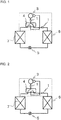
- Fig. 1 is a refrigerant circuit diagram for illustrating an air-conditioning apparatus during a heating operation according to Embodiment 1 of the present invention.
- a four-way valve 4 is switched to the heating operation (see the solid line of Fig. 1 ).
- a compressor 3 the four-way valve 4, an indoor heat exchanger 6, an expansion valve 5, an outdoor heat exchanger 7, and the four-way valve 4 are annularly connected through refrigerant pipes.
- Mufflers 1 are mufflers for an air-conditioning apparatus, and are connected to a refrigerant pipe extending from a discharge port of the compressor 3 to the four-way valve 4, and connected to a refrigerant pipe extending from the four-way valve 4 to the indoor heat exchanger 6.
- the indoor heat exchanger 6 positioned on a discharge port side of the compressor 3 functions as a condenser to perform the heating operation.
- Fig. 2 is a refrigerant circuit diagram for illustrating the air-conditioning apparatus during a cooling operation according to Embodiment 1 of the present invention.
- the four-way valve 4 is switched to the cooling operation (see the solid line of Fig. 2 ).
- the compressor 3, the four-way valve 4, the outdoor heat exchanger 7, the expansion valve 5, the indoor heat exchanger 6, and the four-way valve 4 are annularly connected through the refrigerant pipes.
- the Mufflers 1 are connected to the refrigerant pipe extending from the discharge port of the compressor 3 to the four-way valve 4, and connected to the refrigerant pipe extending from the indoor heat exchanger 6 to the four-way valve 4.
- the indoor heat exchanger 6 positioned on downstream of the expansion valve 5 functions as an evaporator to perform the cooling operation.
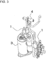
- Fig. 3 is an external view for illustrating a part of the refrigerant circuit of Fig. 1 and Fig. 2 , which is surrounded by the dotted line. Illustration is made of the mufflers 1, the compressor 3, the four-way valve 4, and the refrigerant pipes connecting those devices, which construct the air-conditioning apparatus.
- Fig. 4 is a sectional view for illustrating the muffler 1 of Fig. 1 to Fig. 3 .
- the muffler 1 is mounted to the refrigerant circuit of the air-conditioning apparatus, at least to the refrigerant pipe connected to the discharge port side of the compressor 3.
- the muffler 1 includes a muffler main body 8, an inlet pipe 9, and an outlet pipe 13.
- the muffler main body 8 is constructed of a tubular body in which an inlet small diameter portion 8a is connected through an enlarged diameter portion 8b to a large diameter portion 8c, and the large diameter portion 8c is connected through a reduced diameter portion 8d to an outlet small diameter portion 8e.
- the inlet pipe 9 is connected to the inlet small diameter portion 8a of the muffler main body 8.
- the outlet pipe 13 is connected to the outlet small diameter portion 8e of the muffler main body 8.
- the inlet pipe 9 is inserted through the inlet small diameter portion 8a of the muffler main body 8 into the muffler main body 8, and has an inserted pipe portion 10 having a length L 1 from a starting point 8bs of the enlarged diameter portion 8b of the muffler main body 8.
- a distal end of the inserted pipe portion 10 is positioned at a center of a length from an inlet to an outlet of the muffler main body 8.
- the inserted pipe portion 10 has an upper inserted pipe portion 11 and a lower inserted pipe portion 12.
- the upper inserted pipe portion 11 is a portion of a length L 2 from the starting point 8bs of the enlarged diameter portion 8b of the muffler main body 8.
- the upper inserted pipe portion 11 has an inner diameter equal to that of an upstream portion of the inlet pipe 9 with respect to the inlet small diameter portion 8a of the main body 8.
- the lower inserted pipe portion 12 is a portion of a length L 3 , which is continuous with the upper inserted pipe portion 11.
- the inner diameter of the lower inserted pipe portion 12 is set smaller than that of the upper inserted pipe portion 11.
- a ratio of an inner diameter D of the muffler main body 8 to an inner diameter D 2 of the lower inserted pipe portion 12 is set to satisfy D/D 2 >5.7.
- a length of the inserted pipe portion 10 is represented by L 1 .
- a length of the upper inserted pipe portion 11 of the inserted pipe portion 10 is represented by L 2 .
- a length of the lower inserted pipe portion 12 of the inserted pipe portion 10 is represented by L 3 .
- the relationship among those lengths is set to satisfy 1.5 ⁇ L 3 /L 2 ⁇ 3.
- the ratio of the inner diameter D of the muffler main body 8 to the inner diameter D 2 of the lower inserted pipe portion 12 is set to satisfy D/D 2 >5.7, and a ratio of the length of the lower inserted pipe portion 12 to the length of the upper inserted pipe portion 11 is set to satisfy 1.5 ⁇ L 3 /L 2 ⁇ 3.
- the pressure loss can be reduced by 66% to a maximum.
- both of this embodiment and Patent Literature 1 have the same values in the length L of the muffler main body 8, the inner diameter D of the muffler main body 8, the length L 1 of the inserted pipe portion 10, and the inner diameter D 1 of the inlet pipe 9.
- the inner diameter D of the muffler main body 8 is 28 mm to 32 mm
- the length L of the muffler main body 8 is 60 mm to 100 mm
- the length L 1 of the inserted pipe portion 10 is 30 mm to 50 mm.
- the ratio of the inner diameter D of the muffler main body 8 to the inner diameter D 2 of the lower inserted pipe portion 12 is a fixed value
- the ratio of the length L 3 of the lower inserted pipe portion 12 to the length L 2 of the upper inserted pipe portion 11, which can be manufactured satisfies 1.5 ⁇ L 3 /L 2 ⁇ 3.
- the pressure loss of the muffler in this embodiment is compared to that of the muffler having the inserted pipe portion 10 reduced in diameter from the inlet of the muffler main body 8, it is verified that the pressure loss is reduced by 33% to 66%.
- the ratio of the inner diameter D of the muffler main body 8 to the inner diameter D 2 of the lower inserted pipe portion 12 increases. Therefore, when the ratio is set to satisfy D/D 2 >5.7 as described above, the muffling effect is enhanced.
- the inner diameter of the muffler main body 8 needs to be set about 1.3 times larger than that of this embodiment.
- the muffling effect can be enhanced by reducing the inner diameter of the lower inserted pipe portion 12 without increasing the size of the muffler main body 8. Therefore, when the muffler 1 of this embodiment is employed, the muffler for an air-conditioning apparatus having an enhanced muffling effect can be introduced into an existing air-conditioning apparatus without newly designing a configuration of refrigerant circuit pipes of the air-conditioning apparatus.
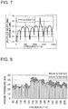
- Fig. 5 to Fig. 7 are graphs for showing muffling properties of the mufflers for an air-conditioning apparatus of the above-mentioned conditions (1) to (3).
- the calculation results of the muffling property are determined with certain conditions of the length L of the muffler main body 8, the length L 1 of the inserted pipe portion 10, the length L 2 of the upper inserted pipe portion 11, the inner diameter D 1 of the upper inserted pipe portion 11, and the length L 3 of the lower inserted pipe portion 12.
- Fig. 5 is a graph for showing the muffling property of the muffler for an air-conditioning apparatus of the above-mentioned condition (1).
- the inner diameter D 1 of the upper inserted pipe portion 11 and the inner diameter D 2 of the lower inserted pipe portion 12 are equal.
- Fig. 6 is a graph for showing the muffling property of the muffler for an air-conditioning apparatus of the above-mentioned condition (2).
- the muffling effect is improved by about 8dB to a maximum (see Fig. 5 and Fig. 6 ). That is, when D/D 2 >5.7 is satisfied as in the muffler for an air-conditioning apparatus of the above-mentioned condition (2), sufficient muffling effect can be obtained as compared to the case of the above-mentioned condition (1).
- Fig. 7 is a graph for showing the muffling property of the muffler for an air-conditioning apparatus of the above-mentioned condition (3).
- D/D 2 5.8
- Fig. 8 is a graph for showing the measurement results, with the mufflers for an air-conditioning apparatus of the above-mentioned conditions (1) and (2) each arranged on the discharge side of the compressor 3 in order to verify the efficacy of the muffling effect described above.
- a pulsation noise generated in the indoor heat exchanger due to a pressure pulsation is measured.
- a comparison is made between a measurement result of the muffler for an air-conditioning apparatus as a reference and a measurement result of the muffler for an air-conditioning apparatus in which the inner diameter D 2 of the lower inserted pipe portion 12 is reduced, it is found that the pulsation noise is reduced. From this point of view, it is found that the high muffling effect can be obtained when an inner diameter ratio is set to satisfy D/D 2 >5.7.
Landscapes
- Engineering & Computer Science (AREA)
- Mechanical Engineering (AREA)
- General Engineering & Computer Science (AREA)
- Chemical & Material Sciences (AREA)
- Combustion & Propulsion (AREA)
- Physics & Mathematics (AREA)
- Thermal Sciences (AREA)
- Compressor (AREA)
- Other Air-Conditioning Systems (AREA)
Applications Claiming Priority (2)
| Application Number | Priority Date | Filing Date | Title |
|---|---|---|---|
| JP2014213880A JP6095628B2 (ja) | 2014-10-20 | 2014-10-20 | 空気調和機用消音器及びその消音器を備えた空気調和機 |
| PCT/JP2015/077953 WO2016063705A1 (ja) | 2014-10-20 | 2015-10-01 | 空気調和機用消音器及びその消音器を備えた空気調和機 |
Publications (3)
| Publication Number | Publication Date |
|---|---|
| EP3211352A1 true EP3211352A1 (de) | 2017-08-30 |
| EP3211352A4 EP3211352A4 (de) | 2018-06-06 |
| EP3211352B1 EP3211352B1 (de) | 2025-03-12 |
Family
ID=55760749
Family Applications (1)
| Application Number | Title | Priority Date | Filing Date |
|---|---|---|---|
| EP15852412.4A Active EP3211352B1 (de) | 2014-10-20 | 2015-10-01 | Klimaanlagendämpfer und klimaanlage mit dem dämpfer |
Country Status (5)
| Country | Link |
|---|---|
| US (1) | US10337748B2 (de) |
| EP (1) | EP3211352B1 (de) |
| JP (1) | JP6095628B2 (de) |
| CN (2) | CN106574814A (de) |
| WO (1) | WO2016063705A1 (de) |
Families Citing this family (12)
| Publication number | Priority date | Publication date | Assignee | Title |
|---|---|---|---|---|
| JP6095628B2 (ja) * | 2014-10-20 | 2017-03-15 | 三菱電機株式会社 | 空気調和機用消音器及びその消音器を備えた空気調和機 |
| BR102016029873A2 (pt) * | 2016-12-19 | 2018-07-17 | Whirlpool S.A. | compressor hermético |
| JP2018162690A (ja) * | 2017-03-24 | 2018-10-18 | 三菱重工サーマルシステムズ株式会社 | 消音器及び空気調和機 |
| CN108826647B (zh) * | 2018-06-13 | 2019-10-01 | 珠海格力电器股份有限公司 | 一种消音器结构和空调器 |
| CN109341051A (zh) * | 2018-10-18 | 2019-02-15 | 广东美的制冷设备有限公司 | 空调用消声器和空调器 |
| DE102019123902A1 (de) * | 2019-09-05 | 2021-03-11 | Hanon Systems | Vorrichtung zum Dämpfen von Druckpulsationen für einen Verdichter eines gasförmigen Fluids |
| CN110822693B (zh) * | 2019-10-30 | 2020-11-27 | 珠海格力电器股份有限公司 | 一种连体消音器结构 |
| EP4033097B1 (de) * | 2020-11-30 | 2024-04-24 | Anhui Meizhi Compressor Co., Ltd. | Saugschalldämpfer |
| KR102443707B1 (ko) * | 2021-01-04 | 2022-09-15 | 엘지전자 주식회사 | 리니어 압축기 |
| KR102523158B1 (ko) * | 2021-01-06 | 2023-04-17 | 엘지전자 주식회사 | 소음저감장치 및 이를 포함하는 에어컨 |
| BE1030415B1 (nl) * | 2022-03-30 | 2023-11-08 | Atlas Copco Airpower Nv | Compressor inrichting en compressor samenstel dat zulke compressor inrichting bevat |
| JP2026019389A (ja) * | 2024-07-26 | 2026-02-05 | 横浜ゴム株式会社 | 樹脂製のサイレンサ |
Family Cites Families (15)
| Publication number | Priority date | Publication date | Assignee | Title |
|---|---|---|---|---|
| JPS5038511U (de) * | 1973-08-06 | 1975-04-21 | ||
| US4122914A (en) * | 1976-04-30 | 1978-10-31 | Nihon Radiator Co., Ltd. | Muffler |
| JPS5921951A (ja) | 1982-07-23 | 1984-02-04 | 三洋電機株式会社 | ヒ−トポンプ式分離型空気調和機 |
| JPH0485076U (de) * | 1990-11-30 | 1992-07-23 | ||
| JPH04292518A (ja) * | 1991-03-20 | 1992-10-16 | Nissan Shatai Co Ltd | 消音装置 |
| JPH09203386A (ja) | 1996-01-25 | 1997-08-05 | Hitachi Ltd | 密閉形圧縮機とこれを用いた冷凍空調システム |
| CN1109221C (zh) * | 1998-07-31 | 2003-05-21 | 海尔集团公司 | 一拖多空调器的制冷系统 |
| CN2468788Y (zh) * | 2001-02-27 | 2002-01-02 | 上海易初通用机器有限公司 | 汽车空调系统的制冷剂管道消音器 |
| KR100774483B1 (ko) * | 2006-01-05 | 2007-11-08 | 엘지전자 주식회사 | 압축기용 흡입머플러 구조 |
| JP5066344B2 (ja) * | 2006-06-21 | 2012-11-07 | ハスクバーナ・ゼノア株式会社 | マフラー |
| KR101386479B1 (ko) * | 2008-03-04 | 2014-04-18 | 엘지전자 주식회사 | 압축기용 머플러 |
| JP2011012869A (ja) * | 2009-07-01 | 2011-01-20 | Panasonic Corp | 空気調和機 |
| CN201935352U (zh) * | 2010-12-10 | 2011-08-17 | 芜湖博耐尔汽车电气系统有限公司 | 一种新型汽车空调系统制冷剂管路消音器 |
| JP5934880B2 (ja) * | 2011-09-14 | 2016-06-15 | パナソニックIpマネジメント株式会社 | 密閉型圧縮機 |
| JP6095628B2 (ja) * | 2014-10-20 | 2017-03-15 | 三菱電機株式会社 | 空気調和機用消音器及びその消音器を備えた空気調和機 |
-
2014
- 2014-10-20 JP JP2014213880A patent/JP6095628B2/ja active Active
-
2015
- 2015-10-01 CN CN201580043791.9A patent/CN106574814A/zh active Pending
- 2015-10-01 EP EP15852412.4A patent/EP3211352B1/de active Active
- 2015-10-01 US US15/503,047 patent/US10337748B2/en active Active
- 2015-10-01 WO PCT/JP2015/077953 patent/WO2016063705A1/ja not_active Ceased
- 2015-10-20 CN CN201520813222.5U patent/CN205137838U/zh not_active Expired - Fee Related
Also Published As
| Publication number | Publication date |
|---|---|
| JP6095628B2 (ja) | 2017-03-15 |
| EP3211352A4 (de) | 2018-06-06 |
| CN106574814A (zh) | 2017-04-19 |
| CN205137838U (zh) | 2016-04-06 |
| US20170234552A1 (en) | 2017-08-17 |
| JP2016080295A (ja) | 2016-05-16 |
| EP3211352B1 (de) | 2025-03-12 |
| WO2016063705A1 (ja) | 2016-04-28 |
| US10337748B2 (en) | 2019-07-02 |
Similar Documents
| Publication | Publication Date | Title |
|---|---|---|
| EP3211352B1 (de) | Klimaanlagendämpfer und klimaanlage mit dem dämpfer | |
| JP2011012869A (ja) | 空気調和機 | |
| CN109996959A (zh) | 消音器以及空气调节器 | |
| CN105758053A (zh) | 喷射器以及具有该喷射器的制冷装置 | |
| US9732741B2 (en) | Hermetic compressor comprising a suction acoustic filter | |
| US7494328B2 (en) | NVH and gas pulsation reduction in AC compressor | |
| CN106403074A (zh) | 一种空调室外机配管系统及空调室外机 | |
| CN204717920U (zh) | 消声器及具有其的空调器室外机 | |
| CN108869303B (zh) | 反相对冲降噪装置和螺杆压缩机 | |
| CN105627474A (zh) | 空调器 | |
| CN104005960A (zh) | 消声器及具有其的空调器 | |
| CN103573636A (zh) | 旋转压缩机及其排气管组件 | |
| KR101956177B1 (ko) | 차량용 공조장치의 머플러 | |
| CN106837750A (zh) | 用于压缩机的排气管、压缩机和制冷设备 | |
| CN103423525A (zh) | 渐缩管、有该渐缩管的制冷系统和具有该制冷系统的冰箱 | |
| CN203614408U (zh) | 旋转压缩机及其排气管组件 | |
| CN204063512U (zh) | 空调器及其消声器 | |
| CN209944714U (zh) | 消音装置及空调器 | |
| CN207299457U (zh) | 制冷系统的配管结构和具有其的制冷系统 | |
| CN207963249U (zh) | 储液器和具有其的压缩机、制冷系统、空调器 | |
| WO2012079141A1 (en) | Discharge acoustic muffler for a refrigeration compressor | |
| CN108317629B (zh) | 空调室外机和空调器 | |
| EP3885690A1 (de) | Wärmetauscher und kühlzyklusvorrichtung | |
| CN217685827U (zh) | 消声器及具有其的空调器 | |
| CN116336708B (zh) | 储液器和压缩机 |
Legal Events
| Date | Code | Title | Description |
|---|---|---|---|
| STAA | Information on the status of an ep patent application or granted ep patent |
Free format text: STATUS: THE INTERNATIONAL PUBLICATION HAS BEEN MADE |
|
| PUAI | Public reference made under article 153(3) epc to a published international application that has entered the european phase |
Free format text: ORIGINAL CODE: 0009012 |
|
| STAA | Information on the status of an ep patent application or granted ep patent |
Free format text: STATUS: REQUEST FOR EXAMINATION WAS MADE |
|
| 17P | Request for examination filed |
Effective date: 20170424 |
|
| AK | Designated contracting states |
Kind code of ref document: A1 Designated state(s): AL AT BE BG CH CY CZ DE DK EE ES FI FR GB GR HR HU IE IS IT LI LT LU LV MC MK MT NL NO PL PT RO RS SE SI SK SM TR |
|
| AX | Request for extension of the european patent |
Extension state: BA ME |
|
| DAV | Request for validation of the european patent (deleted) | ||
| DAX | Request for extension of the european patent (deleted) | ||
| A4 | Supplementary search report drawn up and despatched |
Effective date: 20180509 |
|
| RIC1 | Information provided on ipc code assigned before grant |
Ipc: F24F 1/12 20110101ALI20180503BHEP Ipc: F01N 1/02 20060101ALI20180503BHEP Ipc: F25B 41/00 20060101AFI20180503BHEP Ipc: F04B 39/00 20060101ALI20180503BHEP |
|
| TPAC | Observations filed by third parties |
Free format text: ORIGINAL CODE: EPIDOSNTIPA |
|
| STAA | Information on the status of an ep patent application or granted ep patent |
Free format text: STATUS: EXAMINATION IS IN PROGRESS |
|
| 17Q | First examination report despatched |
Effective date: 20200710 |
|
| GRAP | Despatch of communication of intention to grant a patent |
Free format text: ORIGINAL CODE: EPIDOSNIGR1 |
|
| STAA | Information on the status of an ep patent application or granted ep patent |
Free format text: STATUS: GRANT OF PATENT IS INTENDED |
|
| INTG | Intention to grant announced |
Effective date: 20241016 |
|
| GRAS | Grant fee paid |
Free format text: ORIGINAL CODE: EPIDOSNIGR3 |
|
| GRAA | (expected) grant |
Free format text: ORIGINAL CODE: 0009210 |
|
| STAA | Information on the status of an ep patent application or granted ep patent |
Free format text: STATUS: THE PATENT HAS BEEN GRANTED |
|
| AK | Designated contracting states |
Kind code of ref document: B1 Designated state(s): AL AT BE BG CH CY CZ DE DK EE ES FI FR GB GR HR HU IE IS IT LI LT LU LV MC MK MT NL NO PL PT RO RS SE SI SK SM TR |
|
| REG | Reference to a national code |
Ref country code: GB Ref legal event code: FG4D |
|
| REG | Reference to a national code |
Ref country code: CH Ref legal event code: EP |
|
| REG | Reference to a national code |
Ref country code: DE Ref legal event code: R096 Ref document number: 602015091212 Country of ref document: DE |
|
| REG | Reference to a national code |
Ref country code: IE Ref legal event code: FG4D |
|
| PG25 | Lapsed in a contracting state [announced via postgrant information from national office to epo] |
Ref country code: RS Free format text: LAPSE BECAUSE OF FAILURE TO SUBMIT A TRANSLATION OF THE DESCRIPTION OR TO PAY THE FEE WITHIN THE PRESCRIBED TIME-LIMIT Effective date: 20250612 |
|
| PG25 | Lapsed in a contracting state [announced via postgrant information from national office to epo] |
Ref country code: FI Free format text: LAPSE BECAUSE OF FAILURE TO SUBMIT A TRANSLATION OF THE DESCRIPTION OR TO PAY THE FEE WITHIN THE PRESCRIBED TIME-LIMIT Effective date: 20250312 |
|
| PG25 | Lapsed in a contracting state [announced via postgrant information from national office to epo] |
Ref country code: ES Free format text: LAPSE BECAUSE OF FAILURE TO SUBMIT A TRANSLATION OF THE DESCRIPTION OR TO PAY THE FEE WITHIN THE PRESCRIBED TIME-LIMIT Effective date: 20250312 |
|
| REG | Reference to a national code |
Ref country code: LT Ref legal event code: MG9D |
|
| PG25 | Lapsed in a contracting state [announced via postgrant information from national office to epo] |
Ref country code: NO Free format text: LAPSE BECAUSE OF FAILURE TO SUBMIT A TRANSLATION OF THE DESCRIPTION OR TO PAY THE FEE WITHIN THE PRESCRIBED TIME-LIMIT Effective date: 20250612 |
|
| PG25 | Lapsed in a contracting state [announced via postgrant information from national office to epo] |
Ref country code: HR Free format text: LAPSE BECAUSE OF FAILURE TO SUBMIT A TRANSLATION OF THE DESCRIPTION OR TO PAY THE FEE WITHIN THE PRESCRIBED TIME-LIMIT Effective date: 20250312 |
|
| REG | Reference to a national code |
Ref country code: NL Ref legal event code: MP Effective date: 20250312 |
|
| PG25 | Lapsed in a contracting state [announced via postgrant information from national office to epo] |
Ref country code: LV Free format text: LAPSE BECAUSE OF FAILURE TO SUBMIT A TRANSLATION OF THE DESCRIPTION OR TO PAY THE FEE WITHIN THE PRESCRIBED TIME-LIMIT Effective date: 20250312 |
|
| PG25 | Lapsed in a contracting state [announced via postgrant information from national office to epo] |
Ref country code: GR Free format text: LAPSE BECAUSE OF FAILURE TO SUBMIT A TRANSLATION OF THE DESCRIPTION OR TO PAY THE FEE WITHIN THE PRESCRIBED TIME-LIMIT Effective date: 20250613 Ref country code: BG Free format text: LAPSE BECAUSE OF FAILURE TO SUBMIT A TRANSLATION OF THE DESCRIPTION OR TO PAY THE FEE WITHIN THE PRESCRIBED TIME-LIMIT Effective date: 20250312 |
|
| REG | Reference to a national code |
Ref country code: AT Ref legal event code: MK05 Ref document number: 1775293 Country of ref document: AT Kind code of ref document: T Effective date: 20250312 |
|
| PG25 | Lapsed in a contracting state [announced via postgrant information from national office to epo] |
Ref country code: NL Free format text: LAPSE BECAUSE OF FAILURE TO SUBMIT A TRANSLATION OF THE DESCRIPTION OR TO PAY THE FEE WITHIN THE PRESCRIBED TIME-LIMIT Effective date: 20250312 |
|
| PG25 | Lapsed in a contracting state [announced via postgrant information from national office to epo] |
Ref country code: SE Free format text: LAPSE BECAUSE OF FAILURE TO SUBMIT A TRANSLATION OF THE DESCRIPTION OR TO PAY THE FEE WITHIN THE PRESCRIBED TIME-LIMIT Effective date: 20250312 |
|
| PG25 | Lapsed in a contracting state [announced via postgrant information from national office to epo] |
Ref country code: SM Free format text: LAPSE BECAUSE OF FAILURE TO SUBMIT A TRANSLATION OF THE DESCRIPTION OR TO PAY THE FEE WITHIN THE PRESCRIBED TIME-LIMIT Effective date: 20250312 |
|
| PG25 | Lapsed in a contracting state [announced via postgrant information from national office to epo] |
Ref country code: PT Free format text: LAPSE BECAUSE OF FAILURE TO SUBMIT A TRANSLATION OF THE DESCRIPTION OR TO PAY THE FEE WITHIN THE PRESCRIBED TIME-LIMIT Effective date: 20250714 |
|
| PG25 | Lapsed in a contracting state [announced via postgrant information from national office to epo] |
Ref country code: PL Free format text: LAPSE BECAUSE OF FAILURE TO SUBMIT A TRANSLATION OF THE DESCRIPTION OR TO PAY THE FEE WITHIN THE PRESCRIBED TIME-LIMIT Effective date: 20250312 |
|
| PGFP | Annual fee paid to national office [announced via postgrant information from national office to epo] |
Ref country code: IT Payment date: 20250922 Year of fee payment: 11 |
|
| PG25 | Lapsed in a contracting state [announced via postgrant information from national office to epo] |
Ref country code: AT Free format text: LAPSE BECAUSE OF FAILURE TO SUBMIT A TRANSLATION OF THE DESCRIPTION OR TO PAY THE FEE WITHIN THE PRESCRIBED TIME-LIMIT Effective date: 20250312 |
|
| PG25 | Lapsed in a contracting state [announced via postgrant information from national office to epo] |
Ref country code: EE Free format text: LAPSE BECAUSE OF FAILURE TO SUBMIT A TRANSLATION OF THE DESCRIPTION OR TO PAY THE FEE WITHIN THE PRESCRIBED TIME-LIMIT Effective date: 20250312 Ref country code: CZ Free format text: LAPSE BECAUSE OF FAILURE TO SUBMIT A TRANSLATION OF THE DESCRIPTION OR TO PAY THE FEE WITHIN THE PRESCRIBED TIME-LIMIT Effective date: 20250312 |
|
| PG25 | Lapsed in a contracting state [announced via postgrant information from national office to epo] |
Ref country code: RO Free format text: LAPSE BECAUSE OF FAILURE TO SUBMIT A TRANSLATION OF THE DESCRIPTION OR TO PAY THE FEE WITHIN THE PRESCRIBED TIME-LIMIT Effective date: 20250312 |
|
| PG25 | Lapsed in a contracting state [announced via postgrant information from national office to epo] |
Ref country code: SK Free format text: LAPSE BECAUSE OF FAILURE TO SUBMIT A TRANSLATION OF THE DESCRIPTION OR TO PAY THE FEE WITHIN THE PRESCRIBED TIME-LIMIT Effective date: 20250312 |
|
| PG25 | Lapsed in a contracting state [announced via postgrant information from national office to epo] |
Ref country code: IS Free format text: LAPSE BECAUSE OF FAILURE TO SUBMIT A TRANSLATION OF THE DESCRIPTION OR TO PAY THE FEE WITHIN THE PRESCRIBED TIME-LIMIT Effective date: 20250712 |
|
| REG | Reference to a national code |
Ref country code: DE Ref legal event code: R097 Ref document number: 602015091212 Country of ref document: DE |
|
| PGFP | Annual fee paid to national office [announced via postgrant information from national office to epo] |
Ref country code: DE Payment date: 20250902 Year of fee payment: 11 |
|
| PG25 | Lapsed in a contracting state [announced via postgrant information from national office to epo] |
Ref country code: DK Free format text: LAPSE BECAUSE OF FAILURE TO SUBMIT A TRANSLATION OF THE DESCRIPTION OR TO PAY THE FEE WITHIN THE PRESCRIBED TIME-LIMIT Effective date: 20250312 |
|
| PLBE | No opposition filed within time limit |
Free format text: ORIGINAL CODE: 0009261 |
|
| STAA | Information on the status of an ep patent application or granted ep patent |
Free format text: STATUS: NO OPPOSITION FILED WITHIN TIME LIMIT |
|
| REG | Reference to a national code |
Ref country code: CH Ref legal event code: L10 Free format text: ST27 STATUS EVENT CODE: U-0-0-L10-L00 (AS PROVIDED BY THE NATIONAL OFFICE) Effective date: 20260121 |
|
| 26N | No opposition filed |
Effective date: 20251215 |