EP3211361A1 - Messsonde - Google Patents
Messsonde Download PDFInfo
- Publication number
- EP3211361A1 EP3211361A1 EP17157600.2A EP17157600A EP3211361A1 EP 3211361 A1 EP3211361 A1 EP 3211361A1 EP 17157600 A EP17157600 A EP 17157600A EP 3211361 A1 EP3211361 A1 EP 3211361A1
- Authority
- EP
- European Patent Office
- Prior art keywords
- measuring probe
- detection elements
- signal
- processing circuit
- stylus
- Prior art date
- Legal status (The legal status is an assumption and is not a legal conclusion. Google has not performed a legal analysis and makes no representation as to the accuracy of the status listed.)
- Granted
Links
Images



Classifications
-
- G—PHYSICS
- G01—MEASURING; TESTING
- G01B—MEASURING LENGTH, THICKNESS OR SIMILAR LINEAR DIMENSIONS; MEASURING ANGLES; MEASURING AREAS; MEASURING IRREGULARITIES OF SURFACES OR CONTOURS
- G01B21/00—Measuring arrangements or details thereof, where the measuring technique is not covered by the other groups of this subclass, unspecified or not relevant
-
- G—PHYSICS
- G01—MEASURING; TESTING
- G01B—MEASURING LENGTH, THICKNESS OR SIMILAR LINEAR DIMENSIONS; MEASURING ANGLES; MEASURING AREAS; MEASURING IRREGULARITIES OF SURFACES OR CONTOURS
- G01B7/00—Measuring arrangements characterised by the use of electric or magnetic techniques
- G01B7/004—Measuring arrangements characterised by the use of electric or magnetic techniques for measuring coordinates of points
- G01B7/008—Measuring arrangements characterised by the use of electric or magnetic techniques for measuring coordinates of points using coordinate measuring machines
- G01B7/012—Contact-making feeler heads therefor
-
- G—PHYSICS
- G01—MEASURING; TESTING
- G01B—MEASURING LENGTH, THICKNESS OR SIMILAR LINEAR DIMENSIONS; MEASURING ANGLES; MEASURING AREAS; MEASURING IRREGULARITIES OF SURFACES OR CONTOURS
- G01B21/00—Measuring arrangements or details thereof, where the measuring technique is not covered by the other groups of this subclass, unspecified or not relevant
- G01B21/20—Measuring arrangements or details thereof, where the measuring technique is not covered by the other groups of this subclass, unspecified or not relevant for measuring contours or curvatures, e.g. determining profile
-
- G—PHYSICS
- G01—MEASURING; TESTING
- G01B—MEASURING LENGTH, THICKNESS OR SIMILAR LINEAR DIMENSIONS; MEASURING ANGLES; MEASURING AREAS; MEASURING IRREGULARITIES OF SURFACES OR CONTOURS
- G01B7/00—Measuring arrangements characterised by the use of electric or magnetic techniques
- G01B7/001—Constructional details of gauge heads
Definitions
- the present invention relates to a measuring probe, and in particular to a measuring probe capable of reducing measurement directional dependency of sensitivity with a simple configuration while maintaining high sensitivity.
- a first aspect of the present invention provides a measuring probe including: a stylus having a contact part to be brought into contact with an object to be measured; a probe housing capable of supporting the stylus on an axial center; detection elements capable of detecting a movement of the contact part; and a signal processing circuit that processes outputs of the detection elements.
- the measuring probe includes a plurality of supporting members in an axial direction of the probe housing, the supporting member having a rotationally symmetric shape and allowing for an attitude change of the stylus.
- Four said detection elements are disposed at fourfold symmetric positions in at least one of the plurality of supporting members that includes a deformable arm part.
- the signal processing circuit includes a first processing part that processes the outputs of the detection elements to output three displacement signals representing displacement components of the contact part in mutually perpendicular three directions, respectively.
- a third aspect of the present invention provides the above-described measuring probe, wherein the first processing part includes: a first addition part that adds all of four outputs from the four detection elements; and subtraction parts that subtract, from outputs of two of the detection elements at positions different from each other by an angle of 90 degrees around the axial center, outputs of the detection elements at positions different from the two of the detection elements by an angle of 180 degrees, respectively, and the second processing part include: squaring parts that square the three displacement signals, respectively; and a second addition part that adds all of squared signals outputted from the squaring parts.
- a fifth aspect of the present invention provides the above-described measuring probe, wherein the second processing part further includes multiplication parts that multiply signal levels of the three displacement signals by predetermined coefficients, respectively.
- An eighth aspect of the present invention provides the above-described measuring probe, wherein the signal processing circuit includes any of a low-pass filter, a high-pass filter, and a band-pass filter in a preceding stage of the comparison part.
- the probe main body 302 is supported by a spindle 224 of the drive mechanism 220.
- the stylus module 304 is coupled to the probe main body 302 with a kinematic joint (to be described later) in such a manner that the stylus module 304 can be detached from and attached to the probe main body 302 with high positional reproducibility.
- the measuring probe 300 will be described below in detail. Note that the longitudinal direction on the plane of paper in FIG. 2 is defined as a Z direction, the horizontal direction on the plane of paper is defined as an X direction, and the direction perpendicular to the plane of paper is defined as a Y direction for the purpose of the following description. Therefore, the direction of the axial center O of the measuring probe 300 (axial direction O) coincides with the Z direction.
- the probe housing 306 includes an attachment part 308, a circuit placement part 310, a fixing member 314, a bottom member (wall member) 316, and a main body cover 318.
- the attachment part 308 is a part to be attached to the spindle 224 at the upper end of the measuring probe 300.
- the attachment part 308 is provided with, for example, a head to be inserted into a fitting part provided in the spindle 224.
- the attachment part 308 serves also as one connection terminal capable of electrically connecting to the motion controller 500.
- the other connection terminal 309 is provided on the axial center O of the attachment part 308.
- the attachment part 308 and the connection terminal 309 are connected to the signal processing circuit 320 disposed in the circuit placement part 310 without developing a short circuit with each other by insulating members Mi1 to Mi3.
- the circuit placement part 310 is disposed at the lower end of the attachment part 308.
- the signal processing circuit 320 is a circuit that processes the outputs of the detection elements 325 and outputs a touch signal (contact sensed signal) Sout for notifying that the object W to be measured has been in contact with the contact part 362.
- the signal processing circuit 320 is configured to obtain deflection amounts in the three X, Y, and Z directions from the outputs of the four detection elements 325, combine the deflection amounts in the three directions, and output the touch signal Sout when the contact part 362 has a certain displacement or greater (the specific configuration will be described later).
- the signal processing circuit 320 may be provided with a temperature sensor so that a measurement error of the measuring probe 300 generated due to heat is corrected in accordance with the output of the temperature sensor.
- the supporting members 322 and 324 are elastically-deformable members disposed in the axial direction O of the probe housing 306 that allow for attitude changes of the stylus 336.
- a stainless steel material for example, may be used (other materials may be used) for the supporting members 322 and 324.
- each of the supporting members 322 and 324 has a rotationally symmetric shape including the total of four deformable arm parts at positions shifted from one another by an angle of 90 degrees in the circumferential direction thereof (around the axial center O), as illustrated in FIG. 3 . These four arm parts are formed on the same plane.
- the supporting members 322 and 324 have the same thickness and the same structures except that widths of their arm parts are different from each other (without being limited thereto, the supporting members 322 and 324 may have arm part thicknesses, lengths, and shapes different from each other, or the entire supporting members 322 and 324 may have shapes different from each other). For this reason, the supporting member 324 in which the detection elements 325 are disposed will be described below and a description overlapping with that for the supporting member 322 will be omitted. Note that the structures of the supporting members are not limited to the shapes illustrated in the present embodiment.
- the supporting member 324 is a generally circular plate-shaped member including, in addition to rectangular arm parts 324B, a central part 324A connected to the coupling shaft 326, and a peripheral part 324C coupled to the central part 324A with the arm parts 324B and connected to the probe housing 306.
- the peripheral part 324C is positioned in the outermost portion of the supporting member 324.
- the arm parts 324B extend linearly in a radial direction, and are disposed on the inner side of the peripheral part 324C.
- the central part 324A is disposed on the further inner side of the arm parts 324B.
- the supporting member 324 is configured such that the central part 324A moves vertically and horizontally by a displacement of the coupling shaft 326 with respect to the probe housing 306 and the arm parts 324B elastically deform accordingly.
- the permanent magnet 330 is fixed to the lower surface of the flange member 328 on the axial center O.
- the three balls 332 are disposed with rotational symmetry at intervals of 120 degrees in the circumferential direction on a lower end periphery of the flange member 328 so as to surround the permanent magnet 330.
- the aforementioned stylus module 304 includes an over-travel mechanism 334 and the stylus 336 supported by the over-travel mechanism 334.
- the flange part 338 is a member corresponding to the flange member 328. More specifically, the flange part 338 is provided with three V-grooves 340 at intervals of 120 degrees in the circumferential direction of the flange part 338 so as to be in contact with the balls 332.
- a magnetic member (which may be a permanent magnet) 342 attracted to the permanent magnet 330 is disposed in the flange part 338 so as to face the permanent magnet 330.
- the V-grooves 340 are each to be in contact with the surface of the corresponding ball 332 as illustrated in FIG. 2 .
- the flange part 338 is seated on (in contact with) the flange member 328 at six points.
- the flange member 328 and the flange part 338 can be coupled to each other while achieving high positioning accuracy.
- the flange part 338 and the flange member 328 constitute a kinematic joint (referred to also as a kinematic coupling; the same applies hereinafter), which is a coupling mechanism wherein they can be detached from and attached to each other.
- This kinematic joint allows for the achievement of high positioning reproducibility even when the probe main body 302 and the stylus module 304 are repeatedly detached from and attached to each other.
- the kinematic joint is not limited to the combination of the V-groove and the ball, but may be a combination of a pair of rollers and a ball. Alternatively, the combination of the V-groove and the ball with the opposite arrangement may be employed.
- the extended part 344 is formed integrally with the outer periphery of the flange part 338.
- the extended part 344 houses the coil spring 350 capable of expanding and contracting in the axial direction O therein.
- the stylus holder 346 is provided at an end of the extended part 344 in the axial direction O.
- the stylus holder 346 is connected to the extended part 344 with bolts.
- the upper surface of the stylus holder 346 closer to the coil spring 350 movably supports the flange part 356 of the stylus 336 pressed by the coil spring 350.
- Three balls 348 are disposed on the upper surface of the stylus holder 346 closer to the coil spring 350 at intervals of 120 degrees in the circumferential direction thereof.
- V-grooves 358 are provided on the lower surface of the flange part 356 at intervals of 120 degrees in the circumferential direction thereof so as to correspond to the balls 348. Note that an axial direction of the V-groove 358 is approximately the same as the radial direction toward the axial center O. In other words, it can be said that the stylus holder 346 and the flange part 356 constitute the aforementioned kinematic joint.
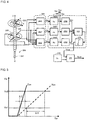
- the first processing part 364 processes the outputs of the detection elements 325 to output three displacement signals Vx, Vy, and Vz representing displacement components of the contact part 362 in the mutually perpendicular three X, Y, and Z directions, respectively.
- the first processing part 364 includes subtraction parts 364X and 364Y and an addition part (first addition part) 364Z, as illustrated in FIG. 4 .
- the subtraction parts 364X and 364Y subtract (calculate a difference) the outputs of the detection elements 325 at positions different from the aforementioned two detection elements 325 by an angle of 180 degrees (in the X direction and in the Y direction), respectively.
- the subtraction parts 364X and 364Y then output the displacement signals Vx and Vy, respectively.
- the addition part 364Z adds all of the four outputs from the four detection elements 325.
- the addition part 364Z then outputs the displacement signal Vz.
- the second processing part 366 outputs a composite signal Vout obtained by combining the three displacement signals Vx, Vy, and Vz.
- the second processing part 366 includes: three multiplication parts 368X, 368Y, and 368Z; three squaring parts 370X, 370Y, and 370Z; an addition part (second addition part) 372; and a square-root operation part 374, as illustrated in FIG. 4 .
- the three multiplication parts 368X, 368Y, and 368Z multiply the signal levels of the displacement signals Vx, Vy, and Vz by predetermined coefficients Kx, Ky, and Kz, respectively, to change the signal levels of the displacement signals Vx, Vy, and Vz relative to one another.
- the predetermined coefficients Kx, Ky, and Kz are set, when a first reference value Vs1 and a second reference value Vs2 are respectively set as predetermined reference values Vs, so as to calibrate differences among the displacement amounts of the contact part 362 in the three X, Y, and Z directions when the composite signal Vout reaches the second reference value Vs2 from the first reference value Vs1.
- this calibration makes the amounts of displacement of the contact part 362 identical with one another in the three X, Y, and Z directions when the composite signal Vout is changed from the first reference value Vs1 to the second reference value Vs2.
- all of the predetermined coefficients Kx, Ky, and Kz may be the same, two of the predetermined coefficients Kx, Ky, and Kz may be the same, or the predetermined coefficients Kx, Ky, and Kz may be different from one another.
- a signal processing circuit 420 includes a filter part 475 in the second embodiment.
- a low-pass filter, a high-pass filter, or a band-pass filter may be set in the filter part 475.
- the low-pass filter can effectively eliminate the effects of noise due to disturbance vibration, electrical noise, and probe vibration due to the movement of the probe.
- the high-pass filter can eliminate an effect such as the one which causes the output of a detection element 425 to fluctuate gently due to an influence of temperature, for example, and the effect of noise close to a DC component generated by the attitude (for example, horizontal attitude) of the measuring probe 300.
- the band-pass filter can eliminate the effects of the aforementioned ranges.
- the filter part is not limited thereto as long as the filter part is provided in the preceding stage of the comparison part.
- the present invention can be applied to a wide range of measuring probes used for measuring three-dimensional shapes of objects to be measured. In doing so, the present invention can be applied not only to measuring probes for coordinate measuring machines but also to measuring probes used in machine tools.
Landscapes
- Physics & Mathematics (AREA)
- General Physics & Mathematics (AREA)
- A Measuring Device Byusing Mechanical Method (AREA)
- Length Measuring Devices With Unspecified Measuring Means (AREA)
Applications Claiming Priority (1)
| Application Number | Priority Date | Filing Date | Title |
|---|---|---|---|
| JP2016036473A JP6212148B2 (ja) | 2016-02-26 | 2016-02-26 | 測定プローブ |
Publications (2)
| Publication Number | Publication Date |
|---|---|
| EP3211361A1 true EP3211361A1 (de) | 2017-08-30 |
| EP3211361B1 EP3211361B1 (de) | 2018-04-11 |
Family
ID=58158916
Family Applications (1)
| Application Number | Title | Priority Date | Filing Date |
|---|---|---|---|
| EP17157600.2A Active EP3211361B1 (de) | 2016-02-26 | 2017-02-23 | Messsonde |
Country Status (4)
| Country | Link |
|---|---|
| US (1) | US10415949B2 (de) |
| EP (1) | EP3211361B1 (de) |
| JP (1) | JP6212148B2 (de) |
| CN (1) | CN107131853B (de) |
Families Citing this family (15)
| Publication number | Priority date | Publication date | Assignee | Title |
|---|---|---|---|---|
| JP6484108B2 (ja) * | 2015-05-22 | 2019-03-13 | 株式会社ミツトヨ | 形状測定装置の制御方法 |
| WO2017182875A1 (en) * | 2016-04-21 | 2017-10-26 | Mitutoyo Corporation | Coordinate measurement probe body |
| JP6341962B2 (ja) | 2016-08-26 | 2018-06-13 | 株式会社ミツトヨ | 三次元測定装置及び座標補正方法 |
| JP6295299B2 (ja) | 2016-08-26 | 2018-03-14 | 株式会社ミツトヨ | 座標補正方法及び三次元測定装置 |
| JP2018031754A (ja) | 2016-08-26 | 2018-03-01 | 株式会社ミツトヨ | 三次元測定装置及び座標補正方法 |
| CN110118515B (zh) * | 2018-02-06 | 2020-12-08 | 清华大学深圳研究生院 | 一种验证手术针下针精度的方法和装置 |
| CN108895953B (zh) * | 2018-05-11 | 2020-08-21 | 深圳清华大学研究院 | 接触式测头、三坐标测量机及对刀仪 |
| JP6738883B2 (ja) * | 2018-11-28 | 2020-08-12 | 株式会社ミツトヨ | プローブユニット及び測定システム |
| JP6898966B2 (ja) * | 2019-06-07 | 2021-07-07 | 株式会社ミツトヨ | 不具合判定ユニット |
| JP7530272B2 (ja) * | 2020-11-06 | 2024-08-07 | 株式会社ミツトヨ | 形状測定装置および異常検出方法 |
| US11644299B2 (en) * | 2020-12-31 | 2023-05-09 | Mitutoyo Corporation | Inductive position sensor signal gain control for coordinate measuring machine probe |
| US11733021B2 (en) | 2021-12-22 | 2023-08-22 | Mitutoyo Corporation | Modular configuration for coordinate measuring machine probe |
| US12188765B2 (en) | 2022-09-07 | 2025-01-07 | Mitutoyo Corporation | Adjustable update rate for measuring probe |
| US12287194B2 (en) * | 2022-11-29 | 2025-04-29 | Mitutoyo Corporation | Motion mechanism for measuring probe |
| US12488448B2 (en) | 2023-07-20 | 2025-12-02 | Mitutoyo Corporation | Machine vision system with objective lens and collision protection |
Citations (4)
| Publication number | Priority date | Publication date | Assignee | Title |
|---|---|---|---|---|
| US5345689A (en) * | 1991-05-25 | 1994-09-13 | Renishaw Metrology Limited | Measuring probe |
| JPH09507918A (ja) | 1994-11-17 | 1997-08-12 | レニショウ パブリック リミテッド カンパニー | 接触プローブ |
| DE10122200A1 (de) * | 2001-05-08 | 2002-11-14 | Zeiss Carl | Tastkopf für ein Koordinatenmeßgerät. Koordinatenmeßgerät, Kalibrierkörper für ein Koordinatenmeßgerät und Verfahren zum Kalibrieren eines Koordinatenmeßgerätes |
| US20040118000A1 (en) * | 2001-02-23 | 2004-06-24 | Roland Roth | Coordinate measuring apparatus for contacting a workpiece, touch probe for a coordinate measuring apparatus and method of operating a coordinate measuring apparatus |
Family Cites Families (49)
| Publication number | Priority date | Publication date | Assignee | Title |
|---|---|---|---|---|
| US4158919A (en) * | 1976-03-24 | 1979-06-26 | Rolls-Royce Limited | Apparatus for measuring displacement in at least two orthogonal dimensions |
| US4866854A (en) * | 1986-12-05 | 1989-09-19 | The Charles Stark Draper Laboratory, Inc. | Multiple axis displacement sensor |
| JPH04178509A (ja) * | 1990-11-13 | 1992-06-25 | Tokyo Seimitsu Co Ltd | 座標測定機の測定方法 |
| EP0521703B1 (de) * | 1991-07-03 | 1995-11-02 | Renishaw Metrology Limited | Signalverarbeitungsschaltung für Triggersonde |
| US5210410A (en) * | 1991-09-26 | 1993-05-11 | The Board Of Trustees Of The Leland Stanford Junior University | Scanning probe microscope having scan correction |
| DE4204602A1 (de) * | 1992-02-15 | 1993-08-19 | Zeiss Carl Fa | Verfahren zur koordinatenmessung an werkstuecken |
| JP2587565B2 (ja) * | 1992-05-28 | 1997-03-05 | 株式会社ミツトヨ | 倣いプローブ |
| DE69323289T3 (de) * | 1992-12-24 | 2003-04-24 | Renishaw Plc, Wotton-Under-Edge | Tastsonde und Signalverarbeitungsschaltung dafür |
| DE4325744C1 (de) * | 1993-07-31 | 1994-12-15 | Heidenhain Gmbh Dr Johannes | Mehrkoordinaten-Tastkopf |
| JP3075981B2 (ja) * | 1996-04-05 | 2000-08-14 | 松下電器産業株式会社 | 形状測定装置 |
| US5822877A (en) * | 1996-06-20 | 1998-10-20 | Brown & Sharpe Manufacturing Company | Multi-probe system for dimensional metrology |
| US6044569A (en) * | 1997-02-10 | 2000-04-04 | Mitutoyo Corporation | Measuring method and measuring instrument |
| JP3285320B2 (ja) | 1997-02-17 | 2002-05-27 | 株式会社ミツトヨ | タッチ信号プローブ |
| US6131301A (en) * | 1997-07-18 | 2000-10-17 | Renishaw Plc | Method of and apparatus for measuring workpieces using a coordinate positioning machine |
| GB2336433B (en) * | 1998-04-14 | 2002-02-06 | Mitutoyo Corp | Touch signal probe |
| JP3130289B2 (ja) * | 1998-08-04 | 2001-01-31 | 株式会社ミツトヨ | タッチ信号プローブ |
| GB2348706B (en) * | 1999-04-02 | 2003-09-24 | Mitutoyo Corp | Movement control mechanism of contact-type vibrating probe |
| JP3819250B2 (ja) * | 2000-05-15 | 2006-09-06 | 株式会社ミツトヨ | 加振型接触検出センサ |
| JP3500125B2 (ja) * | 2001-02-14 | 2004-02-23 | 株式会社ミツトヨ | 弾性体の振動検出システム |
| JP3820357B2 (ja) * | 2001-08-07 | 2006-09-13 | 株式会社ミツトヨ | 計測方法および計測装置 |
| JP2003065748A (ja) * | 2001-08-29 | 2003-03-05 | Mitsutoyo Corp | 測定装置 |
| JP3961258B2 (ja) * | 2001-10-10 | 2007-08-22 | 株式会社ミツトヨ | タッチセンサ、および微細形状測定装置用プローブ |
| US6895359B2 (en) * | 2002-11-25 | 2005-05-17 | Mitutoyo Corporation | Workpiece coordinate system origin setting method, workpiece coordinate system origin setting program and workpiece coordinate system origin setting device of a surface property measuring machine |
| GB0228368D0 (en) * | 2002-12-05 | 2003-01-08 | Renishaw Plc | Probe for high speed scanning |
| GB2417090A (en) * | 2003-04-28 | 2006-02-15 | Stephen James Crampton | CMM arm with exoskeleton |
| JP4330388B2 (ja) * | 2003-07-28 | 2009-09-16 | 株式会社ミツトヨ | 倣いプローブ |
| JP4695374B2 (ja) * | 2003-11-25 | 2011-06-08 | 株式会社ミツトヨ | 表面倣い測定装置および倣いプローブの補正テーブル作成方法 |
| US7693325B2 (en) * | 2004-01-14 | 2010-04-06 | Hexagon Metrology, Inc. | Transprojection of geometry data |
| GB0506158D0 (en) * | 2005-03-24 | 2005-05-04 | Renishaw Plc | Measurement probe |
| JP2007040822A (ja) * | 2005-08-03 | 2007-02-15 | Mitsutoyo Corp | ワーク測定方法 |
| JP4828974B2 (ja) * | 2006-03-16 | 2011-11-30 | 株式会社ミツトヨ | ねじ測定方法、ねじ測定用プローブ及びそれを用いたねじ測定装置 |
| JP2007309684A (ja) * | 2006-05-16 | 2007-11-29 | Mitsutoyo Corp | 測定制御装置、表面性状測定装置、および、測定制御方法 |
| DK2190530T3 (en) * | 2007-09-13 | 2018-02-19 | Toby D Henderson | PATIENT POSITIONING SYSTEM |
| JP3140476U (ja) | 2008-01-15 | 2008-03-27 | 株式会社ミツトヨ | 加振型接触検出センサ |
| JP5089428B2 (ja) | 2008-02-21 | 2012-12-05 | 株式会社ミツトヨ | 倣い測定装置 |
| GB0804467D0 (en) * | 2008-03-11 | 2008-04-16 | Renishaw Plc | Touch trigger measurement probe |
| US20110112786A1 (en) * | 2009-11-06 | 2011-05-12 | Hexagon Metrology Ab | Cmm with improved sensors |
| DE102010018250A1 (de) * | 2010-04-23 | 2011-10-27 | Carl Zeiss Industrielle Messtechnik Gmbh | Verfahren zur Koordinatenmessung an Werkstücken auf einem Koordinatenmessgerät |
| IT1402715B1 (it) * | 2010-10-29 | 2013-09-18 | Marposs Spa | Sonda di tastaggio |
| CN202562431U (zh) * | 2012-05-24 | 2012-11-28 | 曹玉 | 一种微位移测量装置 |
| JP6093538B2 (ja) * | 2012-10-11 | 2017-03-08 | 株式会社ミツトヨ | ねじ形状測定方法 |
| JP5747180B2 (ja) * | 2012-12-06 | 2015-07-08 | パナソニックIpマネジメント株式会社 | 形状測定方法および形状測定装置 |
| DE102013001457A1 (de) * | 2013-01-28 | 2014-07-31 | Blum-Novotest Gmbh | In einer Werkstückbearbeitungsmaschine aufzunehmender temperaturkompensierter Messtaster und Verfahren zur Temperaturkompensation eines Messtasters |
| JP6189153B2 (ja) * | 2013-09-18 | 2017-08-30 | 株式会社ミツトヨ | 梃子式測定器 |
| US9429416B2 (en) * | 2013-12-06 | 2016-08-30 | Tesa Sa | Accessory for coordinate measuring machine |
| JP6049786B2 (ja) * | 2015-03-05 | 2016-12-21 | 株式会社ミツトヨ | 測定プローブ |
| US9528824B2 (en) * | 2015-03-31 | 2016-12-27 | Mitutoyo Corporation | Tactile probing system |
| US9791262B2 (en) * | 2015-12-17 | 2017-10-17 | Mitutoyo Corporation | Measurement device with multiplexed position signals |
| US10145666B2 (en) * | 2016-12-19 | 2018-12-04 | Mitutoyo Corporation | Touch probe for CMM including digital signal communication |
-
2016
- 2016-02-26 JP JP2016036473A patent/JP6212148B2/ja not_active Expired - Fee Related
-
2017
- 2017-02-23 US US15/440,280 patent/US10415949B2/en active Active
- 2017-02-23 EP EP17157600.2A patent/EP3211361B1/de active Active
- 2017-02-24 CN CN201710104606.3A patent/CN107131853B/zh active Active
Patent Citations (4)
| Publication number | Priority date | Publication date | Assignee | Title |
|---|---|---|---|---|
| US5345689A (en) * | 1991-05-25 | 1994-09-13 | Renishaw Metrology Limited | Measuring probe |
| JPH09507918A (ja) | 1994-11-17 | 1997-08-12 | レニショウ パブリック リミテッド カンパニー | 接触プローブ |
| US20040118000A1 (en) * | 2001-02-23 | 2004-06-24 | Roland Roth | Coordinate measuring apparatus for contacting a workpiece, touch probe for a coordinate measuring apparatus and method of operating a coordinate measuring apparatus |
| DE10122200A1 (de) * | 2001-05-08 | 2002-11-14 | Zeiss Carl | Tastkopf für ein Koordinatenmeßgerät. Koordinatenmeßgerät, Kalibrierkörper für ein Koordinatenmeßgerät und Verfahren zum Kalibrieren eines Koordinatenmeßgerätes |
Also Published As
| Publication number | Publication date |
|---|---|
| US20170248402A1 (en) | 2017-08-31 |
| CN107131853A (zh) | 2017-09-05 |
| CN107131853B (zh) | 2020-02-07 |
| US10415949B2 (en) | 2019-09-17 |
| JP6212148B2 (ja) | 2017-10-11 |
| EP3211361B1 (de) | 2018-04-11 |
| JP2017151069A (ja) | 2017-08-31 |
Similar Documents
| Publication | Publication Date | Title |
|---|---|---|
| EP3211361B1 (de) | Messsonde | |
| US10393495B2 (en) | Measuring probe | |
| US11268874B2 (en) | Defect judging unit of measuring probe and defect judging method thereof | |
| JP6966471B2 (ja) | 座標測定プローブ本体 | |
| KR101477120B1 (ko) | 정전용량형 6축 힘/토크 센서 | |
| CN111238433B (zh) | 探针单元以及测定系统 | |
| US10078026B2 (en) | Multi-component force-torque sensing device with reduced cross-talk for twist-compression testing machine | |
| EP4379313A1 (de) | Bewegungsmechanismus für eine messsonde | |
| US20250130032A1 (en) | A scanning probe | |
| JP2018532124A (ja) | 力測定装置 | |
| KR101533920B1 (ko) | 정전용량형 3축 힘 센서 | |
| US20240200924A1 (en) | Touch trigger probe with capacitive sensor | |
| KR100605058B1 (ko) | 3차원 측정기용 접촉식 프로브 | |
| Ferreira et al. | Universal characterization method for 3D tactile probing systems | |
| JP2026057388A (ja) | 動的誤差補正機能付き力センサ,および,土台加速度を考慮した動的誤差補正方法 | |
| JP2016109515A (ja) | 三次元座標測定機用プローブヘッド |
Legal Events
| Date | Code | Title | Description |
|---|---|---|---|
| PUAI | Public reference made under article 153(3) epc to a published international application that has entered the european phase |
Free format text: ORIGINAL CODE: 0009012 |
|
| STAA | Information on the status of an ep patent application or granted ep patent |
Free format text: STATUS: THE APPLICATION HAS BEEN PUBLISHED |
|
| AK | Designated contracting states |
Kind code of ref document: A1 Designated state(s): AL AT BE BG CH CY CZ DE DK EE ES FI FR GB GR HR HU IE IS IT LI LT LU LV MC MK MT NL NO PL PT RO RS SE SI SK SM TR |
|
| AX | Request for extension of the european patent |
Extension state: BA ME |
|
| STAA | Information on the status of an ep patent application or granted ep patent |
Free format text: STATUS: REQUEST FOR EXAMINATION WAS MADE |
|
| 17P | Request for examination filed |
Effective date: 20171017 |
|
| RBV | Designated contracting states (corrected) |
Designated state(s): AL AT BE BG CH CY CZ DE DK EE ES FI FR GB GR HR HU IE IS IT LI LT LU LV MC MK MT NL NO PL PT RO RS SE SI SK SM TR |
|
| GRAP | Despatch of communication of intention to grant a patent |
Free format text: ORIGINAL CODE: EPIDOSNIGR1 |
|
| STAA | Information on the status of an ep patent application or granted ep patent |
Free format text: STATUS: GRANT OF PATENT IS INTENDED |
|
| INTG | Intention to grant announced |
Effective date: 20180102 |
|
| GRAS | Grant fee paid |
Free format text: ORIGINAL CODE: EPIDOSNIGR3 |
|
| GRAA | (expected) grant |
Free format text: ORIGINAL CODE: 0009210 |
|
| STAA | Information on the status of an ep patent application or granted ep patent |
Free format text: STATUS: THE PATENT HAS BEEN GRANTED |
|
| AK | Designated contracting states |
Kind code of ref document: B1 Designated state(s): AL AT BE BG CH CY CZ DE DK EE ES FI FR GB GR HR HU IE IS IT LI LT LU LV MC MK MT NL NO PL PT RO RS SE SI SK SM TR |
|
| REG | Reference to a national code |
Ref country code: GB Ref legal event code: FG4D |
|
| REG | Reference to a national code |
Ref country code: CH Ref legal event code: EP |
|
| REG | Reference to a national code |
Ref country code: AT Ref legal event code: REF Ref document number: 988515 Country of ref document: AT Kind code of ref document: T Effective date: 20180415 |
|
| REG | Reference to a national code |
Ref country code: IE Ref legal event code: FG4D |
|
| REG | Reference to a national code |
Ref country code: DE Ref legal event code: R096 Ref document number: 602017000030 Country of ref document: DE |
|
| REG | Reference to a national code |
Ref country code: NL Ref legal event code: MP Effective date: 20180411 |
|
| REG | Reference to a national code |
Ref country code: LT Ref legal event code: MG4D |
|
| PG25 | Lapsed in a contracting state [announced via postgrant information from national office to epo] |
Ref country code: NL Free format text: LAPSE BECAUSE OF FAILURE TO SUBMIT A TRANSLATION OF THE DESCRIPTION OR TO PAY THE FEE WITHIN THE PRESCRIBED TIME-LIMIT Effective date: 20180411 |
|
| PG25 | Lapsed in a contracting state [announced via postgrant information from national office to epo] |
Ref country code: PL Free format text: LAPSE BECAUSE OF FAILURE TO SUBMIT A TRANSLATION OF THE DESCRIPTION OR TO PAY THE FEE WITHIN THE PRESCRIBED TIME-LIMIT Effective date: 20180411 Ref country code: BG Free format text: LAPSE BECAUSE OF FAILURE TO SUBMIT A TRANSLATION OF THE DESCRIPTION OR TO PAY THE FEE WITHIN THE PRESCRIBED TIME-LIMIT Effective date: 20180711 Ref country code: LT Free format text: LAPSE BECAUSE OF FAILURE TO SUBMIT A TRANSLATION OF THE DESCRIPTION OR TO PAY THE FEE WITHIN THE PRESCRIBED TIME-LIMIT Effective date: 20180411 Ref country code: NO Free format text: LAPSE BECAUSE OF FAILURE TO SUBMIT A TRANSLATION OF THE DESCRIPTION OR TO PAY THE FEE WITHIN THE PRESCRIBED TIME-LIMIT Effective date: 20180711 Ref country code: ES Free format text: LAPSE BECAUSE OF FAILURE TO SUBMIT A TRANSLATION OF THE DESCRIPTION OR TO PAY THE FEE WITHIN THE PRESCRIBED TIME-LIMIT Effective date: 20180411 Ref country code: FI Free format text: LAPSE BECAUSE OF FAILURE TO SUBMIT A TRANSLATION OF THE DESCRIPTION OR TO PAY THE FEE WITHIN THE PRESCRIBED TIME-LIMIT Effective date: 20180411 Ref country code: AL Free format text: LAPSE BECAUSE OF FAILURE TO SUBMIT A TRANSLATION OF THE DESCRIPTION OR TO PAY THE FEE WITHIN THE PRESCRIBED TIME-LIMIT Effective date: 20180411 Ref country code: SE Free format text: LAPSE BECAUSE OF FAILURE TO SUBMIT A TRANSLATION OF THE DESCRIPTION OR TO PAY THE FEE WITHIN THE PRESCRIBED TIME-LIMIT Effective date: 20180411 |
|
| PG25 | Lapsed in a contracting state [announced via postgrant information from national office to epo] |
Ref country code: HR Free format text: LAPSE BECAUSE OF FAILURE TO SUBMIT A TRANSLATION OF THE DESCRIPTION OR TO PAY THE FEE WITHIN THE PRESCRIBED TIME-LIMIT Effective date: 20180411 Ref country code: RS Free format text: LAPSE BECAUSE OF FAILURE TO SUBMIT A TRANSLATION OF THE DESCRIPTION OR TO PAY THE FEE WITHIN THE PRESCRIBED TIME-LIMIT Effective date: 20180411 Ref country code: GR Free format text: LAPSE BECAUSE OF FAILURE TO SUBMIT A TRANSLATION OF THE DESCRIPTION OR TO PAY THE FEE WITHIN THE PRESCRIBED TIME-LIMIT Effective date: 20180712 Ref country code: LV Free format text: LAPSE BECAUSE OF FAILURE TO SUBMIT A TRANSLATION OF THE DESCRIPTION OR TO PAY THE FEE WITHIN THE PRESCRIBED TIME-LIMIT Effective date: 20180411 |
|
| REG | Reference to a national code |
Ref country code: AT Ref legal event code: MK05 Ref document number: 988515 Country of ref document: AT Kind code of ref document: T Effective date: 20180411 |
|
| PG25 | Lapsed in a contracting state [announced via postgrant information from national office to epo] |
Ref country code: PT Free format text: LAPSE BECAUSE OF FAILURE TO SUBMIT A TRANSLATION OF THE DESCRIPTION OR TO PAY THE FEE WITHIN THE PRESCRIBED TIME-LIMIT Effective date: 20180813 |
|
| REG | Reference to a national code |
Ref country code: DE Ref legal event code: R097 Ref document number: 602017000030 Country of ref document: DE |
|
| PG25 | Lapsed in a contracting state [announced via postgrant information from national office to epo] |
Ref country code: RO Free format text: LAPSE BECAUSE OF FAILURE TO SUBMIT A TRANSLATION OF THE DESCRIPTION OR TO PAY THE FEE WITHIN THE PRESCRIBED TIME-LIMIT Effective date: 20180411 Ref country code: SK Free format text: LAPSE BECAUSE OF FAILURE TO SUBMIT A TRANSLATION OF THE DESCRIPTION OR TO PAY THE FEE WITHIN THE PRESCRIBED TIME-LIMIT Effective date: 20180411 Ref country code: CZ Free format text: LAPSE BECAUSE OF FAILURE TO SUBMIT A TRANSLATION OF THE DESCRIPTION OR TO PAY THE FEE WITHIN THE PRESCRIBED TIME-LIMIT Effective date: 20180411 Ref country code: AT Free format text: LAPSE BECAUSE OF FAILURE TO SUBMIT A TRANSLATION OF THE DESCRIPTION OR TO PAY THE FEE WITHIN THE PRESCRIBED TIME-LIMIT Effective date: 20180411 Ref country code: EE Free format text: LAPSE BECAUSE OF FAILURE TO SUBMIT A TRANSLATION OF THE DESCRIPTION OR TO PAY THE FEE WITHIN THE PRESCRIBED TIME-LIMIT Effective date: 20180411 Ref country code: DK Free format text: LAPSE BECAUSE OF FAILURE TO SUBMIT A TRANSLATION OF THE DESCRIPTION OR TO PAY THE FEE WITHIN THE PRESCRIBED TIME-LIMIT Effective date: 20180411 |
|
| PLBE | No opposition filed within time limit |
Free format text: ORIGINAL CODE: 0009261 |
|
| STAA | Information on the status of an ep patent application or granted ep patent |
Free format text: STATUS: NO OPPOSITION FILED WITHIN TIME LIMIT |
|
| PG25 | Lapsed in a contracting state [announced via postgrant information from national office to epo] |
Ref country code: IT Free format text: LAPSE BECAUSE OF FAILURE TO SUBMIT A TRANSLATION OF THE DESCRIPTION OR TO PAY THE FEE WITHIN THE PRESCRIBED TIME-LIMIT Effective date: 20180411 Ref country code: SM Free format text: LAPSE BECAUSE OF FAILURE TO SUBMIT A TRANSLATION OF THE DESCRIPTION OR TO PAY THE FEE WITHIN THE PRESCRIBED TIME-LIMIT Effective date: 20180411 |
|
| 26N | No opposition filed |
Effective date: 20190114 |
|
| PG25 | Lapsed in a contracting state [announced via postgrant information from national office to epo] |
Ref country code: MC Free format text: LAPSE BECAUSE OF FAILURE TO SUBMIT A TRANSLATION OF THE DESCRIPTION OR TO PAY THE FEE WITHIN THE PRESCRIBED TIME-LIMIT Effective date: 20180411 Ref country code: LU Free format text: LAPSE BECAUSE OF NON-PAYMENT OF DUE FEES Effective date: 20190223 |
|
| REG | Reference to a national code |
Ref country code: BE Ref legal event code: MM Effective date: 20190228 |
|
| REG | Reference to a national code |
Ref country code: IE Ref legal event code: MM4A |
|
| PG25 | Lapsed in a contracting state [announced via postgrant information from national office to epo] |
Ref country code: IE Free format text: LAPSE BECAUSE OF NON-PAYMENT OF DUE FEES Effective date: 20190223 |
|
| PG25 | Lapsed in a contracting state [announced via postgrant information from national office to epo] |
Ref country code: BE Free format text: LAPSE BECAUSE OF NON-PAYMENT OF DUE FEES Effective date: 20190228 |
|
| PG25 | Lapsed in a contracting state [announced via postgrant information from national office to epo] |
Ref country code: TR Free format text: LAPSE BECAUSE OF FAILURE TO SUBMIT A TRANSLATION OF THE DESCRIPTION OR TO PAY THE FEE WITHIN THE PRESCRIBED TIME-LIMIT Effective date: 20180411 |
|
| PG25 | Lapsed in a contracting state [announced via postgrant information from national office to epo] |
Ref country code: MT Free format text: LAPSE BECAUSE OF NON-PAYMENT OF DUE FEES Effective date: 20190223 |
|
| REG | Reference to a national code |
Ref country code: CH Ref legal event code: PL |
|
| PG25 | Lapsed in a contracting state [announced via postgrant information from national office to epo] |
Ref country code: CH Free format text: LAPSE BECAUSE OF NON-PAYMENT OF DUE FEES Effective date: 20200229 Ref country code: LI Free format text: LAPSE BECAUSE OF NON-PAYMENT OF DUE FEES Effective date: 20200229 |
|
| PG25 | Lapsed in a contracting state [announced via postgrant information from national office to epo] |
Ref country code: CY Free format text: LAPSE BECAUSE OF FAILURE TO SUBMIT A TRANSLATION OF THE DESCRIPTION OR TO PAY THE FEE WITHIN THE PRESCRIBED TIME-LIMIT Effective date: 20180411 |
|
| PG25 | Lapsed in a contracting state [announced via postgrant information from national office to epo] |
Ref country code: IS Free format text: LAPSE BECAUSE OF FAILURE TO SUBMIT A TRANSLATION OF THE DESCRIPTION OR TO PAY THE FEE WITHIN THE PRESCRIBED TIME-LIMIT Effective date: 20180811 |
|
| PG25 | Lapsed in a contracting state [announced via postgrant information from national office to epo] |
Ref country code: HU Free format text: LAPSE BECAUSE OF FAILURE TO SUBMIT A TRANSLATION OF THE DESCRIPTION OR TO PAY THE FEE WITHIN THE PRESCRIBED TIME-LIMIT; INVALID AB INITIO Effective date: 20170223 |
|
| PG25 | Lapsed in a contracting state [announced via postgrant information from national office to epo] |
Ref country code: SI Free format text: LAPSE BECAUSE OF FAILURE TO SUBMIT A TRANSLATION OF THE DESCRIPTION OR TO PAY THE FEE WITHIN THE PRESCRIBED TIME-LIMIT Effective date: 20180411 |
|
| PG25 | Lapsed in a contracting state [announced via postgrant information from national office to epo] |
Ref country code: MK Free format text: LAPSE BECAUSE OF FAILURE TO SUBMIT A TRANSLATION OF THE DESCRIPTION OR TO PAY THE FEE WITHIN THE PRESCRIBED TIME-LIMIT Effective date: 20180411 |
|
| PGFP | Annual fee paid to national office [announced via postgrant information from national office to epo] |
Ref country code: GB Payment date: 20260219 Year of fee payment: 10 |
|
| PGFP | Annual fee paid to national office [announced via postgrant information from national office to epo] |
Ref country code: DE Payment date: 20260218 Year of fee payment: 10 |
|
| PGFP | Annual fee paid to national office [announced via postgrant information from national office to epo] |
Ref country code: FR Payment date: 20260218 Year of fee payment: 10 |