EP3211408B1 - Capteur d'humidite relative et procede - Google Patents
Capteur d'humidite relative et procede Download PDFInfo
- Publication number
- EP3211408B1 EP3211408B1 EP16157892.7A EP16157892A EP3211408B1 EP 3211408 B1 EP3211408 B1 EP 3211408B1 EP 16157892 A EP16157892 A EP 16157892A EP 3211408 B1 EP3211408 B1 EP 3211408B1
- Authority
- EP
- European Patent Office
- Prior art keywords
- electrode
- sensitive layer
- relative humidity
- humidity sensor
- composition
- Prior art date
- Legal status (The legal status is an assumption and is not a legal conclusion. Google has not performed a legal analysis and makes no representation as to the accuracy of the status listed.)
- Active
Links
Images


Classifications
-
- G—PHYSICS
- G01—MEASURING; TESTING
- G01N—INVESTIGATING OR ANALYSING MATERIALS BY DETERMINING THEIR CHEMICAL OR PHYSICAL PROPERTIES
- G01N27/00—Investigating or analysing materials by the use of electric, electrochemical, or magnetic means
- G01N27/02—Investigating or analysing materials by the use of electric, electrochemical, or magnetic means by investigating impedance
- G01N27/22—Investigating or analysing materials by the use of electric, electrochemical, or magnetic means by investigating impedance by investigating capacitance
- G01N27/223—Investigating or analysing materials by the use of electric, electrochemical, or magnetic means by investigating impedance by investigating capacitance for determining moisture content, e.g. humidity
- G01N27/225—Investigating or analysing materials by the use of electric, electrochemical, or magnetic means by investigating impedance by investigating capacitance for determining moisture content, e.g. humidity by using hygroscopic materials
-
- G—PHYSICS
- G01—MEASURING; TESTING
- G01N—INVESTIGATING OR ANALYSING MATERIALS BY DETERMINING THEIR CHEMICAL OR PHYSICAL PROPERTIES
- G01N27/00—Investigating or analysing materials by the use of electric, electrochemical, or magnetic means
- G01N27/02—Investigating or analysing materials by the use of electric, electrochemical, or magnetic means by investigating impedance
- G01N27/22—Investigating or analysing materials by the use of electric, electrochemical, or magnetic means by investigating impedance by investigating capacitance
- G01N27/226—Construction of measuring vessels; Electrodes therefor
Definitions
- Relative humidity sensors can be used in various domestic and industrial environments.
- relative humidity sensors can be used for control of the living environment in buildings, textiles and paper manufacturing, food processing, the medical field, the automotive industry, pharmaceutical processing, agriculture, and chemical gas purification, among others.
- US2003/0179805 discloses a capacitance type humidity sensor composed of a substrate having two interdigitated electrodes thereon, a passivation layer and a humidity sensitive layer.
- the present invention provides a relative humidity sensor and a method of forming a relative humidity sensor as defined in the appended claims.
- the present disclosure is directed toward a relative humidity sensor and a method for making the relative humidity sensor.
- the relative humidity sensor incorporates a moisture humidity sensitive layer formed from a composition comprising cellulose acetate butyrate and a hydrophobic filler.
- the hydrophobic filler can, in an example, be an organic compound, such as a lignin or barium sulphate.
- the hydrophobic filler can be an inorganic compound, such as talc.
- the relative humidity sensor can, in an example, be formed in stacked configuration or in an interdigitated configuration.
- Capacitive sensors are commonly used at least due in part to their linear response. That is, the amount of water absorbed, which is proportional to the relative humidity of the environment, is linearly proportional to the change of the dielectric constant of the insulating polymer of the capacitive sensor.
- Previous and current capacitive sensors can suffer from hysteresis. Previous approaches have attempted to mitigate the hysteresis problem by incorporation of hydrophobic carbon black within the polymer. However, carbon black is not fully compatible with polymer matrices.
- the present disclosure provides a relative humidity sensor including a humidity sensitive layer formed of cellulose acetate butyrate and a compatible hydrophobic filler, so as to reduce the hysteresis by more than 50% (e.g., from about 50% to about 100%; about 60 % to about 90%; about 70% to about 95%; about 80% to about 99%; or about 75% to about 100%) with respect to previous solutions based on carbon black incorporation.
- a humidity sensitive layer formed of cellulose acetate butyrate and a compatible hydrophobic filler
- the hydrophobic filler makes the sensing layer more hydrophobic and thus the chance of forming water clusters as a function of relative humidity (RH) increase is decreased significantly.
- RH relative humidity
- a more hydrophobic humidity sensitive layer will have a smaller dielectric constant variation as a function of the relative humidity increase and a smaller capacitance variation between 0% RH and 100% RH.
- the changes in the dielectric constant as a function of RH can be smaller than 10-20%, the impact on hysteresis can be much higher.
- the hysteresis can be reduced by more than 50% by incorporating the hydrophobic fillers of the various embodiments described herein.
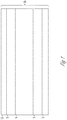
- FIG. 1 shows a cross-sectional view of a relative humidity sensor 10 (hereinafter "sensor 10"), in accordance with at least one embodiment of the invention.
- the sensor 10 illustrated in FIG. 1 is a stacked configuration, but examples are not so limited (e.g., FIG. 2 and 3 ).
- the sensor 10 includes a dielectric substrate 2.
- the dielectric substrate 2 can be formed of a flexible dielectric material such that the dielectric substrate 2 can conform to non-planar surfaces.
- the dielectric substrate 22 is not flexible.
- the dielectric substrate 2 can include a polymer, such as cellulose acetate butyrate.
- the dielectric substrate 2, in an example, can be formed from commercially available cellulose acetate butyrate, such as is available from Eastman (Kingsport, TN) (with thickness from 1 to 2 ⁇ m).
- the sensor 10 includes a first electrode 4 and a second electrode 8.
- the first electrode 4 and the second electrode 8 can have the same composition or can be formed of different compositions.
- the first electrode 4, the second electrode 8, or both is formed from a conductive polymer, such as a polymer including conductive carbon (e.g., carbon black), with thickness from 1 to 2 ⁇ m for layers deposited by, e.g, maskless, direct printing.
- the first electrode 4, the second electrode 8, or both are formed from conductive Kapton®.
- the first electrode 4, the second electrode 4, or both can be a conductive material such as metal (e.g., titanium, platinum or a titanium/platinum alloy).
- the sensor 10 includes a humidity sensitive layer 6, of thickness, e.g., from 1 to 2 ⁇ m for layers deposited by spin coating or maskless direct printing.
- the humidity sensitive layer 6 is formed from a curable composition comprising cellulose acetate butyrate and a hydrophobic filler.
- the cellulose acetate butyrate can be any suitable polymer of the formula:
- R is hydrogen, acetate (-C(O)CH 3 ) or butyrate (-C(O)CH 2 CH 2 CH 3 ); and n is an integer such that the molecular weight of the cellulose acetate butyrate is from about 12,000 g/mol to about 70,000g/mol (e.g., from about 12,000 g/mol to about 60,000 g/mol; about 30,000 g/mol to about 65,000 g/mol; and about 15,000 to about 55,000 g/mol).
- the composition can be prepared by mixing the cellulose acetate butyrate with the hydrophobic filler (e.g., a solution of cellulose acetate butyrate in a suitable organic solvent is mixed with the hydrophobic filler).
- the composition includes about 5% to about 10 % by weight of a hydrophobic filler based on a total weight of the composition (e.g., about 5% to about 8% by weight of a hydrophobic filler based on a total weight of the composition).
- the hydrophobic filler can include an organic compound such as Viton and lignin.
- the organic compound can, in an example, include one or more lignin of varying molecular weights.
- One possible benefit of including lignin in the composition can include reducing water up-take of the humidity sensitive layer 6 formed from the composition.
- the lignin can have an average molecular weight from about 400 g/mol to about 1,100 g/mol (e.g., about 500 g/mol to about 1,000 g/mol; about 600 g/mol to about 800 g/mol; or about an average molecular weight of about 500 g/mol to about 1000 g/mol).
- the composition can include about 5% to about 10% by weight lignin based on a total weight of the composition (e.g., about 5% to about 8% by weight lignin based on a total weight of the composition).
- the hydrophobic filler can include an inorganic compound.
- the inorganic compound can, in an example include at least one of calcium carbonate, barium sulphate, talc, synthetic fluorine mica, and wollastonite.
- talc e.g., talc nanoparticles having at least one dimension in the range of about 1 nanometer (nm) to about 100 nm
- the filler can increase the hydrophobicity of the cellulose acetate butyrate used in forming the humidity sensitive layer 6, and finally decrease its hysteresis.
- te hysteresis decrease can be explained by a much lower amount of water vapors incorporated as liquid-phase water clusters in the more hydrophobic sensing film.
- the dielectric constant will increase much slower as a function of relative humidity increase, and the same will happen with the capacitance of the sensor as a function of the RH increase. But the hysteresis will be decreased significantly.
- Lower range in the capacitance variation as a function of RH variation may be solved by the increase in the amplification of the electronic amplifier for signal processing.
- the composition includes about 5% to about 10% by weight of a hydrophobic filler based on a total weight of the composition (e.g., about 5% to about 8% by weight of a hydrophobic filler based on a total weight of the composition).
- the sensor 10 can include, in some embodiments, a dust protection layer 12 disposed above the humidity sensitive layer 6, with thickness of, for example, 1 to 2 ⁇ m.
- the dust protection layer 12 is formed from a polymer, such as a cellulose acetate butyrate.
- the dust protection layer 12 acts, in some embodiments, as a barrier against dust and in the same time it is porous enough to allow air and humidity to reach the sensing layer without affecting the response time of the sensor.
- This dust protection layer can be formed from the same or different material as the dielectric substrate 2. In an example, due its higher porosity with respect to sensing layer, the dust protection layer 12 can have a lower capacitance than humidity sensitive layer 6.
- the dust protection layer 12 can, in an example, be formed from commercially available Kapton®.
- FIG. 1 illustrates the sensor 10 in a stacked configuration.
- a stacked configuration can include the second electrode 8 disposed above the first electrode 4. As shown, the first electrode 4 and the second electrode 8 are separated by the humidity sensitive layer 6.
- the humidity sensitive layer 6 can be in electrical contact with the first electrode 4 and the second electrode 8. That is, the sensor 10 can include a stacked configuration, from bottom to top, including the dielectric substrate 2, the first electrode 4, the humidity sensitive layer 6, the second electrode 8, and the dust protective layer 12, when the dust layer is present.
- the sensor 10 is shown as having a rectangular cross-sectional geometry, examples are not so limited.
- the sensor 10 can include a tapered configuration, such as a taper from bottom to top or top to bottom.
- FIG. 2 shows a partial cut-away perspective view of a relative humidity sensor 20 (hereinafter also referred to as "sensor 20"), in accordance with at least one example.
- the sensor 20 is similar to sensor 10 as described in relation to FIG. 1 , but illustrates an interdigitated configuration.
- the sensor 20 includes a dielectric substrate 22, similar to the dielectric substrate 2 described in relation to FIG. 1 .
- the sensor 20 can include interdigitated electrodes (IDEs), including the first electrode 24 and the second electrode 26, both of which are supported by the dielectric substrate 22.
- IDEs 24, 26 can be supported by the dielectric substrate 22 such as be depositing the IDEs 24, 26 on a surface of the dielectric substrate, as described herein.
- the first and second electrodes 24, 26 can include two individually addressable interdigitated comb-like electrode structures.
- the first and second electrodes 24, 26 can be direct printed on the dielectric substrate 2.
- the first and second electrodes 24, 26 can include the same materials as the first and second electrodes 4, 6 described in relation to sensor 10 of FIG. 1 .
- the sensor 20 includes a humidity sensitive layer 28 configured to detect humidity of the environment in which the sensor 20 is located. That is, the humidity sensitive layer 28 can be in electrical contact with the IDEs, such that dielectric properties of the sensor 20 can vary based on the interaction between the humidity sensitive layer 28 and the first and second electrodes 24, 26.
- the humidity sensitive layer 28 is formed of the composition of a cellulose acetate butyrate and a hydrophobic filler, as discussed herein.
- the sensor 20, as shown can include a dust protection layer 29. As shown in FIG. 2 , in an example, the dust protection layer 29 can cover at least a top surface of the humidity sensitive layer 28.
- the dust protection layer 29 can be formed from the same materials as discussed in connection with the dust protection layer 12 of sensor 10 in FIG. 1 .
- FIG. 3 shows a cross-sectional view 30 of the sensor 20 in FIG. 2 .
- the sensor includes the dielectric substrate 22.
- the dielectric substrate 22 can include the materials described above with respect to the dielectric substrate (e.g., 2, FIG. 1 ).
- the interdigitated electrodes, the first electrode 24 and the second electrode 26, can be deposited on the dielectric substrate 22, such as by a direct printing method.
- the humidity sensitive layer 28 can be deposited on the IDEs so as to encompass the first and second electrodes 24, 26 and form a thin layer above the IDEs.
- the sensor can include the dust protection film 29 above the humidity sensitive layer 28, as described herein.
- FIG. 4 illustrates a method 40 of forming a relative humidity sensor, in accordance with at least one embodiment of the invention.
- the method 40 includes depositing a first electrode on a dielectric substrate, such as the dielectric substrate 2 of FIG. 1 .
- the first electrode can include an electrode as described herein, such as the first electrode 4 of FIG. 1 .
- depositing the first electrode can include direct printing.
- the method 40 includes applying a composition to an upper surface of the first electrode to form a humidity sensitive layer, at 44.
- the composition includes a cellulose acetate butyrate and a hydrophobic filler, as described herein.
- the composition can be prepared by dissolving the hydrophobic filler in a suitable solvent such as dimethylformamide (DMF), N-methylformamide (NMF) or combinations thereof.
- a suitable solvent such as dimethylformamide (DMF), N-methylformamide (NMF) or combinations thereof.
- the hydrophobic filler can include an organic compound, such as a lignin, as described herein.
- the method 40 includes depositing a second electrode on an upper surface of the humidity sensitive layer, such as the second electrode 8 as described in relation to FIG. 1 .
- the method 40 includes depositing a dust protection layer, such as the dust protection layer 12 of FIG. 1 , on an upper surface of the second electrode, so as to form the relative humidity sensor.
- FIG. 5 illustrates a method 50 of forming a humidity sensor, in accordance with at least one other embodiment of the invention.
- the method includes preparing a composition including a cellulose acetate butyrate and a hydrophobic filler, as described herein.
- the composition prepared at 52 can be prepared by any method described herein, such as in relation to FIGS. 1-4 .
- the method 50 includes depositing at least a portion of the composition on a dielectric substrate supporting a first electrode and a second electrode, wherein the first and the second electrode are interdigitated (24, 26 of FIG. 2 ), to form the relative humidity sensor (20 of FIG. 3 ).
- the method 50 can include depositing a dust protection layer on at least an upper surface of the second electrode, as described herein.
- Ti/Pt Ti/Pt electrode
- a cellulose acetate butyrate solution (10%) by dissolving cellulose acetate butyrate powder in ethyl alcohol.
- Wollastonite slurry (hydrophobic filler; 3%) was prepared from unmodified wollastonite and ethyl alcohol, ultrasonically stirred at room temperature, for 24 hours.
- the wollastonite slurry is then mixed with the cellulose acetate butyrate solution and the mixture is ultrasonically stirred at room temperature, for 24 hours.
- the cellulose acetate butyrate solution comprising the wollastonite suspended therein can be spin-coated (5 to 500 rpm for 50 seconds) onto the lower electrode and placed in an oven to cure in air: 30 minutes at 150°C. The temperature was then slowly ramped down to room temperature.
- a porous platinum electrode having a thickness of from about 20 to about 40 nm is then deposited and patterned on top of the cured cellulose acetate butyrate comprising wollastonite.
- a cellulose acetate butyrate film can be spin coated on the surface of upper electrode, which acts as a dust removal thin film.
- the terms “a” or “an” are used to include one or more than one, independent of any other instances or usages of “at least one” or “one or more.”
- the term “or” is used to refer to a nonexclusive or, such that “A or B” includes “A but not B,” “B but not A,” and “A and B,” unless otherwise indicated.
Landscapes
- Chemical & Material Sciences (AREA)
- Chemical Kinetics & Catalysis (AREA)
- Electrochemistry (AREA)
- Physics & Mathematics (AREA)
- Health & Medical Sciences (AREA)
- Life Sciences & Earth Sciences (AREA)
- Analytical Chemistry (AREA)
- Biochemistry (AREA)
- General Health & Medical Sciences (AREA)
- General Physics & Mathematics (AREA)
- Immunology (AREA)
- Pathology (AREA)
- Investigating Or Analyzing Materials By The Use Of Electric Means (AREA)
- Investigating Or Analyzing Materials By The Use Of Fluid Adsorption Or Reactions (AREA)
Claims (13)
- Capteur d'humidité relative, comprenant :un substrat diélectrique (2 ; 22) ;une première électrode et une deuxième électrode (4, 8 ; 24, 26) disposées au-dessus du substrat diélectrique (2 ; 22) ; etune couche sensible à l'humidité (6 ; 28) disposée au-dessus de la première électrode et/ou de la deuxième électrode (4, 8 ; 24, 26), la couche sensible à l'humidité (6 ; 28) comprenant une composition comprenant de l'acétobutyrate de cellulose et une charge hydrophobe ;dans lequel la couche sensible à l'humidité (6 ; 28) comprend environ 5 à environ 10 pour cent en poids de charge hydrophobe, rapporté au poids total de la couche sensible à l'humidité (6 ; 28).
- Capteur d'humidité relative de la revendication 1, comprenant en outre une couche de protection contre la poussière (12 ; 29) disposée au-dessus de la couche sensible à l'humidité (6 ; 28).
- Capteur d'humidité relative de la revendication 1, dans lequel la charge hydrophobe est un composé organique.
- Capteur d'humidité relative de la revendication 1, dans lequel la charge hydrophobe comprend de la lignine.
- Capteur d'humidité relative de la revendication 4, dans lequel la couche sensible à l'humidité (6 ; 28) comprend environ 5 à environ 10 pour cent en poids de lignine, rapporté au poids total de la couche sensible à l'humidité (6 ; 28) .
- Capteur d'humidité relative de la revendication 5, dans lequel la lignine a un poids moléculaire moyen d'environ 500 à environ 1000 g/mol.
- Capteur d'humidité relative de la revendication 1, dans lequel la charge hydrophobe est un composé inorganique.
- Capteur d'humidité relative de la revendication 7, dans lequel les composés inorganiques comprend au moins un composé parmi le carbonate de calcium, le sulfate de baryum, le talc, le mica fluoré synthétique, et la wollastonite.
- Capteur d'humidité relative de la revendication 1, dans lequel la couche sensible à l'humidité (6) est disposée au-dessus de la première électrode (4) et la deuxième électrode (8) est disposée au-dessus de la couche sensible à l'humidité (6).
- Capteur d'humidité relative de la revendication 1, dans lequel la première électrode (24) et la deuxième électrode (26) sont interdigitées et la couche sensible l'humidité (28) est disposée au-dessus de la première électrode (24) et de la deuxième électrode (26).
- Capteur d'humidité relative de la revendication 2, dans lequel la couche de protection contre la poussière (12 ; 29) est poreuse.
- Procédé de formation d'un capteur d'humidité relative, le procédé comprenant :le dépôt d'une première électrode (4) sur un substrat diélectrique (2) ;l'application d'une composition à une surface supérieure de la première électrode (4) pour former une couche sensible à l'humidité (6), la composition comprenant une composition comprenant de l'acétobutyrate de cellulose et une charge hydrophobe, la couche sensible à l'humidité (6) comprenant environ 5 à environ 10 pour cent en poids de charge hydrophobe, rapporté au poids total de la couche sensible à l'humidité (6) ;le dépôt d'une deuxième électrode (8) sur une surface supérieure de la couche sensible à l'humidité (6) ; etle dépôt d'une couche de protection contre la poussière (12) sur une surface supérieure de la deuxième électrode (8).
- Procédé de formation d'un capteur d'humidité relative, le procédé comprenant :la préparation d'une composition, la composition comprenant une composition comprenant de l'acétobutyrate de cellulose et une charge hydrophobe ; etle dépôt d'au moins une partie de la composition sur un substrat diélectrique (22) supportant une première électrode (24) et une deuxième électrode (26) pour former une couche sensible à l'humidité (28), la couche sensible à l'humidité (28) comprenant environ 5 à environ 10 pour cent en poids de charge hydrophobe, rapporté au poids total de la couche sensible à l'humidité (28), et la première et la deuxième électrode (24, 26) étant interdigitées, pour former le capteur d'humidité relative.
Priority Applications (2)
| Application Number | Priority Date | Filing Date | Title |
|---|---|---|---|
| EP16157892.7A EP3211408B1 (fr) | 2016-02-29 | 2016-02-29 | Capteur d'humidite relative et procede |
| US15/423,349 US10634636B2 (en) | 2016-02-29 | 2017-02-02 | Relative humidity sensor and method |
Applications Claiming Priority (1)
| Application Number | Priority Date | Filing Date | Title |
|---|---|---|---|
| EP16157892.7A EP3211408B1 (fr) | 2016-02-29 | 2016-02-29 | Capteur d'humidite relative et procede |
Publications (2)
| Publication Number | Publication Date |
|---|---|
| EP3211408A1 EP3211408A1 (fr) | 2017-08-30 |
| EP3211408B1 true EP3211408B1 (fr) | 2019-04-10 |
Family
ID=55446702
Family Applications (1)
| Application Number | Title | Priority Date | Filing Date |
|---|---|---|---|
| EP16157892.7A Active EP3211408B1 (fr) | 2016-02-29 | 2016-02-29 | Capteur d'humidite relative et procede |
Country Status (2)
| Country | Link |
|---|---|
| US (1) | US10634636B2 (fr) |
| EP (1) | EP3211408B1 (fr) |
Families Citing this family (4)
| Publication number | Priority date | Publication date | Assignee | Title |
|---|---|---|---|---|
| DE102016207260B3 (de) * | 2016-04-28 | 2017-01-12 | Robert Bosch Gmbh | Mikromechanische Feuchtesensorvorrichtung und entsprechendes Herstellungsverfahren |
| CN209326840U (zh) | 2018-12-27 | 2019-08-30 | 热敏碟公司 | 压力传感器及压力变送器 |
| CN110530934B (zh) * | 2019-08-29 | 2022-05-10 | 业成科技(成都)有限公司 | 湿度感测器及其制造方法 |
| KR102524148B1 (ko) * | 2019-12-13 | 2023-04-21 | 한국전자기술연구원 | 정전용량형 습도센서 및 그의 제조방법 |
Family Cites Families (19)
| Publication number | Priority date | Publication date | Assignee | Title |
|---|---|---|---|---|
| US4603372A (en) * | 1984-11-05 | 1986-07-29 | Direction De La Meteorologie Du Ministere Des Transports | Method of fabricating a temperature or humidity sensor of the thin film type, and sensors obtained thereby |
| US4965698A (en) * | 1989-09-27 | 1990-10-23 | Johnson Service Company | Capacitance humidity sensor |
| US5161085A (en) * | 1991-02-21 | 1992-11-03 | Yamatake-Honeywell Co., Ltd. | Moisture sensitive element and method of manufacturing the same |
| US5408381A (en) * | 1994-04-28 | 1995-04-18 | Johnson Service Company | Capacitance humidity sensor |
| US6114863A (en) * | 1998-04-29 | 2000-09-05 | General Electric Company | Method for determining the presence of water in materials |
| EP1369683A4 (fr) * | 2001-03-13 | 2008-06-18 | Tdk Corp | Element de capteur d'humidite et procede de fabrication correspondant |
| US6806722B2 (en) * | 2001-12-07 | 2004-10-19 | Samsung Electronics Co., Ltd. | Polymer-type humidity sensor |
| JP2003270189A (ja) * | 2002-03-20 | 2003-09-25 | Denso Corp | 容量式湿度センサ |
| JP2004271461A (ja) * | 2003-03-11 | 2004-09-30 | Denso Corp | 容量式湿度センサ |
| JP2005003543A (ja) * | 2003-06-12 | 2005-01-06 | Nippon Soken Inc | 湿度センサ用感湿素子 |
| JP5112639B2 (ja) * | 2006-03-06 | 2013-01-09 | トウプラスエンジニアリング株式会社 | 湿度センサ |
| FR2932490B1 (fr) * | 2008-06-13 | 2012-11-02 | Rhodia Operations | Composition polyamide. |
| US20100307238A1 (en) * | 2009-06-05 | 2010-12-09 | The Governors Of The University Of Alberta | Humidity sensor and method of manufacturing the same |
| EP2420826A1 (fr) * | 2010-08-17 | 2012-02-22 | Nxp B.V. | Circuit intégré et son procédé de fabrication |
| US8920731B2 (en) * | 2010-09-20 | 2014-12-30 | Kimberly-Clark Worldwide, Inc. | Nonwoven-based chemi-capacitive or chemi-resistive gas sensor |
| FR2972261B1 (fr) * | 2011-03-03 | 2013-04-12 | Commissariat Energie Atomique | Capteur d'humidite comprenant comme couche absorbante d'humidite une couche polymerique comprenant un melange de polyamides |
| CN104583763B (zh) * | 2012-06-25 | 2017-03-08 | 3M创新有限公司 | 传感器元件及其制备和使用方法 |
| US10107773B2 (en) * | 2012-10-29 | 2018-10-23 | MEMS-Vision International Inc. | Methods and systems for humidity and pressure sensor overlay integration with electronics |
| EP3259581B1 (fr) * | 2015-02-17 | 2020-01-29 | Honeywell International Inc. | Capteur d'humidité et procédé de fabrication du capteur |
-
2016
- 2016-02-29 EP EP16157892.7A patent/EP3211408B1/fr active Active
-
2017
- 2017-02-02 US US15/423,349 patent/US10634636B2/en active Active
Non-Patent Citations (1)
| Title |
|---|
| None * |
Also Published As
| Publication number | Publication date |
|---|---|
| EP3211408A1 (fr) | 2017-08-30 |
| US10634636B2 (en) | 2020-04-28 |
| US20170248537A1 (en) | 2017-08-31 |
Similar Documents
| Publication | Publication Date | Title |
|---|---|---|
| EP3211408B1 (fr) | Capteur d'humidite relative et procede | |
| JP5800897B2 (ja) | 可変静電容量センサ及びその作製方法 | |
| Rivadeneyra et al. | A printed capacitive–resistive double sensor for toluene and moisture sensing | |
| Wang et al. | Flexible chemiresistor sensors: thin film assemblies of nanoparticles on a polyethylene terephthalate substrate | |
| US10429333B2 (en) | Relative humidity sensor and method | |
| US9671359B2 (en) | Resistive type humidity sensor based on porous magnesium ferrite pellet | |
| US20170097313A1 (en) | Humidity sensor | |
| US8132457B2 (en) | Nano-porous alumina sensor | |
| US20190250117A1 (en) | Capacitive gas sensor | |
| KR102040216B1 (ko) | 나노구조물의 네트워크 구조를 갖는 가스센서 및 가스센서의 제조방법 | |
| Miramirkhani et al. | Morphology, structure, and gas sensing performance of conductive polymers and polymer/carbon black composites used for volatile compounds detection | |
| Lyuleeva et al. | Functionalized and oxidized silicon nanosheets: Customized design for enhanced sensitivity towards relative humidity | |
| EP3749963A2 (fr) | Éléments de détection comprenant du noir de carbone sur lequel sont greffées des nanoparticules d'or | |
| Manoli et al. | Polymer‐BaTiO3 composites: Dielectric constant and vapor sensing properties in chemocapacitor applications | |
| WO2018230382A1 (fr) | Dispositif de détection | |
| JP7245693B2 (ja) | センサ及びその製造方法 | |
| CN108279266B (zh) | 电化学检测器 | |
| KR101876942B1 (ko) | 이산화티탄 미립자가 혼합된 기능성 폴리머를 이용한 고감도 저 히스테리시스 다공성 mim 타입 용량성 습도 센서 | |
| Nenova et al. | Humidity sensing elements based on Zn-doped TiO2 films prepared via a sol-gel method | |
| JPH0765977B2 (ja) | ガスセンサ用の不活性、触媒作用性またはガス感受性セラミック層の製造法 | |
| Soukup et al. | Advanced screen printing for the fabrication of organic humidity sensors | |
| JP2001249099A (ja) | 静電容量式湿度センサおよび湿度測定装置 | |
| Huck et al. | Multi‐parameter sensing using high‐k oxide of barium strontium titanate | |
| KR101882401B1 (ko) | 이산화티탄 미립자가 혼합된 기능성 폴리머를 이용한 고감도 저 히스테리시스 다공성 mim 타입 용량성 습도 센서 제조 방법 | |
| JP2009002802A (ja) | 被水センサおよび結露センサ |
Legal Events
| Date | Code | Title | Description |
|---|---|---|---|
| PUAI | Public reference made under article 153(3) epc to a published international application that has entered the european phase |
Free format text: ORIGINAL CODE: 0009012 |
|
| STAA | Information on the status of an ep patent application or granted ep patent |
Free format text: STATUS: REQUEST FOR EXAMINATION WAS MADE |
|
| 17P | Request for examination filed |
Effective date: 20160229 |
|
| AK | Designated contracting states |
Kind code of ref document: A1 Designated state(s): AL AT BE BG CH CY CZ DE DK EE ES FI FR GB GR HR HU IE IS IT LI LT LU LV MC MK MT NL NO PL PT RO RS SE SI SK SM TR |
|
| AX | Request for extension of the european patent |
Extension state: BA ME |
|
| RIN1 | Information on inventor provided before grant (corrected) |
Inventor name: BUIU, OCTAVIAN Inventor name: COBIANU, CORNEL P. Inventor name: BREZEANU, MIHAI Inventor name: SERBAN, BOGDAN-CATALIN |
|
| GRAP | Despatch of communication of intention to grant a patent |
Free format text: ORIGINAL CODE: EPIDOSNIGR1 |
|
| STAA | Information on the status of an ep patent application or granted ep patent |
Free format text: STATUS: GRANT OF PATENT IS INTENDED |
|
| INTG | Intention to grant announced |
Effective date: 20181122 |
|
| GRAS | Grant fee paid |
Free format text: ORIGINAL CODE: EPIDOSNIGR3 |
|
| GRAA | (expected) grant |
Free format text: ORIGINAL CODE: 0009210 |
|
| STAA | Information on the status of an ep patent application or granted ep patent |
Free format text: STATUS: THE PATENT HAS BEEN GRANTED |
|
| AK | Designated contracting states |
Kind code of ref document: B1 Designated state(s): AL AT BE BG CH CY CZ DE DK EE ES FI FR GB GR HR HU IE IS IT LI LT LU LV MC MK MT NL NO PL PT RO RS SE SI SK SM TR |
|
| REG | Reference to a national code |
Ref country code: GB Ref legal event code: FG4D |
|
| REG | Reference to a national code |
Ref country code: CH Ref legal event code: EP Ref country code: AT Ref legal event code: REF Ref document number: 1119398 Country of ref document: AT Kind code of ref document: T Effective date: 20190415 |
|
| REG | Reference to a national code |
Ref country code: IE Ref legal event code: FG4D |
|
| REG | Reference to a national code |
Ref country code: DE Ref legal event code: R096 Ref document number: 602016012080 Country of ref document: DE |
|
| REG | Reference to a national code |
Ref country code: NL Ref legal event code: MP Effective date: 20190410 |
|
| REG | Reference to a national code |
Ref country code: LT Ref legal event code: MG4D |
|
| REG | Reference to a national code |
Ref country code: AT Ref legal event code: MK05 Ref document number: 1119398 Country of ref document: AT Kind code of ref document: T Effective date: 20190410 |
|
| PG25 | Lapsed in a contracting state [announced via postgrant information from national office to epo] |
Ref country code: NL Free format text: LAPSE BECAUSE OF FAILURE TO SUBMIT A TRANSLATION OF THE DESCRIPTION OR TO PAY THE FEE WITHIN THE PRESCRIBED TIME-LIMIT Effective date: 20190410 |
|
| PG25 | Lapsed in a contracting state [announced via postgrant information from national office to epo] |
Ref country code: SE Free format text: LAPSE BECAUSE OF FAILURE TO SUBMIT A TRANSLATION OF THE DESCRIPTION OR TO PAY THE FEE WITHIN THE PRESCRIBED TIME-LIMIT Effective date: 20190410 Ref country code: LT Free format text: LAPSE BECAUSE OF FAILURE TO SUBMIT A TRANSLATION OF THE DESCRIPTION OR TO PAY THE FEE WITHIN THE PRESCRIBED TIME-LIMIT Effective date: 20190410 Ref country code: ES Free format text: LAPSE BECAUSE OF FAILURE TO SUBMIT A TRANSLATION OF THE DESCRIPTION OR TO PAY THE FEE WITHIN THE PRESCRIBED TIME-LIMIT Effective date: 20190410 Ref country code: AL Free format text: LAPSE BECAUSE OF FAILURE TO SUBMIT A TRANSLATION OF THE DESCRIPTION OR TO PAY THE FEE WITHIN THE PRESCRIBED TIME-LIMIT Effective date: 20190410 Ref country code: HR Free format text: LAPSE BECAUSE OF FAILURE TO SUBMIT A TRANSLATION OF THE DESCRIPTION OR TO PAY THE FEE WITHIN THE PRESCRIBED TIME-LIMIT Effective date: 20190410 Ref country code: PT Free format text: LAPSE BECAUSE OF FAILURE TO SUBMIT A TRANSLATION OF THE DESCRIPTION OR TO PAY THE FEE WITHIN THE PRESCRIBED TIME-LIMIT Effective date: 20190910 Ref country code: NO Free format text: LAPSE BECAUSE OF FAILURE TO SUBMIT A TRANSLATION OF THE DESCRIPTION OR TO PAY THE FEE WITHIN THE PRESCRIBED TIME-LIMIT Effective date: 20190710 Ref country code: FI Free format text: LAPSE BECAUSE OF FAILURE TO SUBMIT A TRANSLATION OF THE DESCRIPTION OR TO PAY THE FEE WITHIN THE PRESCRIBED TIME-LIMIT Effective date: 20190410 |
|
| PG25 | Lapsed in a contracting state [announced via postgrant information from national office to epo] |
Ref country code: GR Free format text: LAPSE BECAUSE OF FAILURE TO SUBMIT A TRANSLATION OF THE DESCRIPTION OR TO PAY THE FEE WITHIN THE PRESCRIBED TIME-LIMIT Effective date: 20190711 Ref country code: RS Free format text: LAPSE BECAUSE OF FAILURE TO SUBMIT A TRANSLATION OF THE DESCRIPTION OR TO PAY THE FEE WITHIN THE PRESCRIBED TIME-LIMIT Effective date: 20190410 Ref country code: BG Free format text: LAPSE BECAUSE OF FAILURE TO SUBMIT A TRANSLATION OF THE DESCRIPTION OR TO PAY THE FEE WITHIN THE PRESCRIBED TIME-LIMIT Effective date: 20190710 Ref country code: LV Free format text: LAPSE BECAUSE OF FAILURE TO SUBMIT A TRANSLATION OF THE DESCRIPTION OR TO PAY THE FEE WITHIN THE PRESCRIBED TIME-LIMIT Effective date: 20190410 Ref country code: PL Free format text: LAPSE BECAUSE OF FAILURE TO SUBMIT A TRANSLATION OF THE DESCRIPTION OR TO PAY THE FEE WITHIN THE PRESCRIBED TIME-LIMIT Effective date: 20190410 |
|
| PG25 | Lapsed in a contracting state [announced via postgrant information from national office to epo] |
Ref country code: IS Free format text: LAPSE BECAUSE OF FAILURE TO SUBMIT A TRANSLATION OF THE DESCRIPTION OR TO PAY THE FEE WITHIN THE PRESCRIBED TIME-LIMIT Effective date: 20190810 Ref country code: AT Free format text: LAPSE BECAUSE OF FAILURE TO SUBMIT A TRANSLATION OF THE DESCRIPTION OR TO PAY THE FEE WITHIN THE PRESCRIBED TIME-LIMIT Effective date: 20190410 |
|
| REG | Reference to a national code |
Ref country code: DE Ref legal event code: R097 Ref document number: 602016012080 Country of ref document: DE |
|
| PG25 | Lapsed in a contracting state [announced via postgrant information from national office to epo] |
Ref country code: DK Free format text: LAPSE BECAUSE OF FAILURE TO SUBMIT A TRANSLATION OF THE DESCRIPTION OR TO PAY THE FEE WITHIN THE PRESCRIBED TIME-LIMIT Effective date: 20190410 Ref country code: EE Free format text: LAPSE BECAUSE OF FAILURE TO SUBMIT A TRANSLATION OF THE DESCRIPTION OR TO PAY THE FEE WITHIN THE PRESCRIBED TIME-LIMIT Effective date: 20190410 Ref country code: SK Free format text: LAPSE BECAUSE OF FAILURE TO SUBMIT A TRANSLATION OF THE DESCRIPTION OR TO PAY THE FEE WITHIN THE PRESCRIBED TIME-LIMIT Effective date: 20190410 Ref country code: CZ Free format text: LAPSE BECAUSE OF FAILURE TO SUBMIT A TRANSLATION OF THE DESCRIPTION OR TO PAY THE FEE WITHIN THE PRESCRIBED TIME-LIMIT Effective date: 20190410 Ref country code: RO Free format text: LAPSE BECAUSE OF FAILURE TO SUBMIT A TRANSLATION OF THE DESCRIPTION OR TO PAY THE FEE WITHIN THE PRESCRIBED TIME-LIMIT Effective date: 20190410 |
|
| PLBE | No opposition filed within time limit |
Free format text: ORIGINAL CODE: 0009261 |
|
| STAA | Information on the status of an ep patent application or granted ep patent |
Free format text: STATUS: NO OPPOSITION FILED WITHIN TIME LIMIT |
|
| PG25 | Lapsed in a contracting state [announced via postgrant information from national office to epo] |
Ref country code: IT Free format text: LAPSE BECAUSE OF FAILURE TO SUBMIT A TRANSLATION OF THE DESCRIPTION OR TO PAY THE FEE WITHIN THE PRESCRIBED TIME-LIMIT Effective date: 20190410 Ref country code: SM Free format text: LAPSE BECAUSE OF FAILURE TO SUBMIT A TRANSLATION OF THE DESCRIPTION OR TO PAY THE FEE WITHIN THE PRESCRIBED TIME-LIMIT Effective date: 20190410 |
|
| 26N | No opposition filed |
Effective date: 20200113 |
|
| PG25 | Lapsed in a contracting state [announced via postgrant information from national office to epo] |
Ref country code: TR Free format text: LAPSE BECAUSE OF FAILURE TO SUBMIT A TRANSLATION OF THE DESCRIPTION OR TO PAY THE FEE WITHIN THE PRESCRIBED TIME-LIMIT Effective date: 20190410 |
|
| PG25 | Lapsed in a contracting state [announced via postgrant information from national office to epo] |
Ref country code: SI Free format text: LAPSE BECAUSE OF FAILURE TO SUBMIT A TRANSLATION OF THE DESCRIPTION OR TO PAY THE FEE WITHIN THE PRESCRIBED TIME-LIMIT Effective date: 20190410 |
|
| REG | Reference to a national code |
Ref country code: CH Ref legal event code: PL |
|
| REG | Reference to a national code |
Ref country code: BE Ref legal event code: MM Effective date: 20200229 |
|
| PG25 | Lapsed in a contracting state [announced via postgrant information from national office to epo] |
Ref country code: MC Free format text: LAPSE BECAUSE OF FAILURE TO SUBMIT A TRANSLATION OF THE DESCRIPTION OR TO PAY THE FEE WITHIN THE PRESCRIBED TIME-LIMIT Effective date: 20190410 Ref country code: LU Free format text: LAPSE BECAUSE OF NON-PAYMENT OF DUE FEES Effective date: 20200229 |
|
| PG25 | Lapsed in a contracting state [announced via postgrant information from national office to epo] |
Ref country code: CH Free format text: LAPSE BECAUSE OF NON-PAYMENT OF DUE FEES Effective date: 20200229 Ref country code: LI Free format text: LAPSE BECAUSE OF NON-PAYMENT OF DUE FEES Effective date: 20200229 |
|
| PG25 | Lapsed in a contracting state [announced via postgrant information from national office to epo] |
Ref country code: IE Free format text: LAPSE BECAUSE OF NON-PAYMENT OF DUE FEES Effective date: 20200229 |
|
| PG25 | Lapsed in a contracting state [announced via postgrant information from national office to epo] |
Ref country code: BE Free format text: LAPSE BECAUSE OF NON-PAYMENT OF DUE FEES Effective date: 20200229 |
|
| PG25 | Lapsed in a contracting state [announced via postgrant information from national office to epo] |
Ref country code: MT Free format text: LAPSE BECAUSE OF FAILURE TO SUBMIT A TRANSLATION OF THE DESCRIPTION OR TO PAY THE FEE WITHIN THE PRESCRIBED TIME-LIMIT Effective date: 20190410 Ref country code: CY Free format text: LAPSE BECAUSE OF FAILURE TO SUBMIT A TRANSLATION OF THE DESCRIPTION OR TO PAY THE FEE WITHIN THE PRESCRIBED TIME-LIMIT Effective date: 20190410 |
|
| PG25 | Lapsed in a contracting state [announced via postgrant information from national office to epo] |
Ref country code: MK Free format text: LAPSE BECAUSE OF FAILURE TO SUBMIT A TRANSLATION OF THE DESCRIPTION OR TO PAY THE FEE WITHIN THE PRESCRIBED TIME-LIMIT Effective date: 20190410 |
|
| PGFP | Annual fee paid to national office [announced via postgrant information from national office to epo] |
Ref country code: GB Payment date: 20260223 Year of fee payment: 11 |
|
| PGFP | Annual fee paid to national office [announced via postgrant information from national office to epo] |
Ref country code: DE Payment date: 20260220 Year of fee payment: 11 |
|
| PGFP | Annual fee paid to national office [announced via postgrant information from national office to epo] |
Ref country code: FR Payment date: 20260224 Year of fee payment: 11 |