EP3211533B1 - Architecture de système tolérant aux pannes destinée à commander une installation physique, en particulier une machine ou un véhicule automobile - Google Patents
Architecture de système tolérant aux pannes destinée à commander une installation physique, en particulier une machine ou un véhicule automobile Download PDFInfo
- Publication number
- EP3211533B1 EP3211533B1 EP17157802.4A EP17157802A EP3211533B1 EP 3211533 B1 EP3211533 B1 EP 3211533B1 EP 17157802 A EP17157802 A EP 17157802A EP 3211533 B1 EP3211533 B1 EP 3211533B1
- Authority
- EP
- European Patent Office
- Prior art keywords
- time
- real
- rtswc
- computer system
- messages
- Prior art date
- Legal status (The legal status is an assumption and is not a legal conclusion. Google has not performed a legal analysis and makes no representation as to the accuracy of the status listed.)
- Active
Links
Images

Classifications
-
- G—PHYSICS
- G06—COMPUTING OR CALCULATING; COUNTING
- G06F—ELECTRIC DIGITAL DATA PROCESSING
- G06F11/00—Error detection; Error correction; Monitoring
- G06F11/07—Responding to the occurrence of a fault, e.g. fault tolerance
- G06F11/14—Error detection or correction of the data by redundancy in operations
- G06F11/1402—Saving, restoring, recovering or retrying
- G06F11/1415—Saving, restoring, recovering or retrying at system level
- G06F11/142—Reconfiguring to eliminate the error
-
- G—PHYSICS
- G05—CONTROLLING; REGULATING
- G05B—CONTROL OR REGULATING SYSTEMS IN GENERAL; FUNCTIONAL ELEMENTS OF SUCH SYSTEMS; MONITORING OR TESTING ARRANGEMENTS FOR SUCH SYSTEMS OR ELEMENTS
- G05B19/00—Program-control systems
- G05B19/02—Program-control systems electric
- G05B19/04—Program control other than numerical control, i.e. in sequence controllers or logic controllers
-
- G—PHYSICS
- G05—CONTROLLING; REGULATING
- G05B—CONTROL OR REGULATING SYSTEMS IN GENERAL; FUNCTIONAL ELEMENTS OF SUCH SYSTEMS; MONITORING OR TESTING ARRANGEMENTS FOR SUCH SYSTEMS OR ELEMENTS
- G05B19/00—Program-control systems
- G05B19/02—Program-control systems electric
- G05B19/04—Program control other than numerical control, i.e. in sequence controllers or logic controllers
- G05B19/042—Program control other than numerical control, i.e. in sequence controllers or logic controllers using digital processors
- G05B19/0421—Multiprocessor system
-
- G—PHYSICS
- G06—COMPUTING OR CALCULATING; COUNTING
- G06F—ELECTRIC DIGITAL DATA PROCESSING
- G06F11/00—Error detection; Error correction; Monitoring
- G06F11/07—Responding to the occurrence of a fault, e.g. fault tolerance
- G06F11/14—Error detection or correction of the data by redundancy in operations
- G06F11/1402—Saving, restoring, recovering or retrying
- G06F11/1415—Saving, restoring, recovering or retrying at system level
- G06F11/1438—Restarting or rejuvenating
-
- G—PHYSICS
- G06—COMPUTING OR CALCULATING; COUNTING
- G06F—ELECTRIC DIGITAL DATA PROCESSING
- G06F11/00—Error detection; Error correction; Monitoring
- G06F11/07—Responding to the occurrence of a fault, e.g. fault tolerance
- G06F11/14—Error detection or correction of the data by redundancy in operations
- G06F11/1479—Generic software techniques for error detection or fault masking
- G06F11/1482—Generic software techniques for error detection or fault masking using middleware or operating system [OS] functionalities
- G06F11/1484—Generic software techniques for error detection or fault masking using middleware or operating system [OS] functionalities involving virtual machines
-
- G—PHYSICS
- G06—COMPUTING OR CALCULATING; COUNTING
- G06F—ELECTRIC DIGITAL DATA PROCESSING
- G06F11/00—Error detection; Error correction; Monitoring
- G06F11/07—Responding to the occurrence of a fault, e.g. fault tolerance
- G06F11/16—Error detection or correction of the data by redundancy in hardware
- G06F11/20—Error detection or correction of the data by redundancy in hardware using active fault-masking, e.g. by switching out faulty elements or by switching in spare elements
- G06F11/202—Error detection or correction of the data by redundancy in hardware using active fault-masking, e.g. by switching out faulty elements or by switching in spare elements where processing functionality is redundant
- G06F11/2023—Failover techniques
- G06F11/2025—Failover techniques using centralised failover control functionality
-
- G—PHYSICS
- G06—COMPUTING OR CALCULATING; COUNTING
- G06F—ELECTRIC DIGITAL DATA PROCESSING
- G06F11/00—Error detection; Error correction; Monitoring
- G06F11/07—Responding to the occurrence of a fault, e.g. fault tolerance
- G06F11/16—Error detection or correction of the data by redundancy in hardware
- G06F11/20—Error detection or correction of the data by redundancy in hardware using active fault-masking, e.g. by switching out faulty elements or by switching in spare elements
- G06F11/202—Error detection or correction of the data by redundancy in hardware using active fault-masking, e.g. by switching out faulty elements or by switching in spare elements where processing functionality is redundant
- G06F11/2035—Error detection or correction of the data by redundancy in hardware using active fault-masking, e.g. by switching out faulty elements or by switching in spare elements where processing functionality is redundant without idle spare hardware
-
- H—ELECTRICITY
- H04—ELECTRIC COMMUNICATION TECHNIQUE
- H04L—TRANSMISSION OF DIGITAL INFORMATION, e.g. TELEGRAPHIC COMMUNICATION
- H04L41/00—Arrangements for maintenance, administration or management of data switching networks, e.g. of packet switching networks
- H04L41/04—Network management architectures or arrangements
- H04L41/046—Network management architectures or arrangements comprising network management agents or mobile agents therefor
-
- H—ELECTRICITY
- H04—ELECTRIC COMMUNICATION TECHNIQUE
- H04L—TRANSMISSION OF DIGITAL INFORMATION, e.g. TELEGRAPHIC COMMUNICATION
- H04L67/00—Network arrangements or protocols for supporting network services or applications
- H04L67/01—Protocols
- H04L67/12—Protocols specially adapted for proprietary or special-purpose networking environments, e.g. medical networks, sensor networks, networks in vehicles or remote metering networks
-
- G—PHYSICS
- G06—COMPUTING OR CALCULATING; COUNTING
- G06F—ELECTRIC DIGITAL DATA PROCESSING
- G06F11/00—Error detection; Error correction; Monitoring
- G06F11/07—Responding to the occurrence of a fault, e.g. fault tolerance
- G06F11/16—Error detection or correction of the data by redundancy in hardware
- G06F11/1629—Error detection by comparing the output of redundant processing systems
- G06F11/1641—Error detection by comparing the output of redundant processing systems where the comparison is not performed by the redundant processing components
-
- G—PHYSICS
- G06—COMPUTING OR CALCULATING; COUNTING
- G06F—ELECTRIC DIGITAL DATA PROCESSING
- G06F11/00—Error detection; Error correction; Monitoring
- G06F11/07—Responding to the occurrence of a fault, e.g. fault tolerance
- G06F11/16—Error detection or correction of the data by redundancy in hardware
- G06F11/18—Error detection or correction of the data by redundancy in hardware using passive fault-masking of the redundant circuits
- G06F11/183—Error detection or correction of the data by redundancy in hardware using passive fault-masking of the redundant circuits by voting, the voting not being performed by the redundant components
- G06F11/184—Error detection or correction of the data by redundancy in hardware using passive fault-masking of the redundant circuits by voting, the voting not being performed by the redundant components where the redundant components implement processing functionality
-
- G—PHYSICS
- G06—COMPUTING OR CALCULATING; COUNTING
- G06F—ELECTRIC DIGITAL DATA PROCESSING
- G06F2201/00—Indexing scheme relating to error detection, to error correction, and to monitoring
- G06F2201/805—Real-time
-
- G—PHYSICS
- G06—COMPUTING OR CALCULATING; COUNTING
- G06F—ELECTRIC DIGITAL DATA PROCESSING
- G06F2201/00—Indexing scheme relating to error detection, to error correction, and to monitoring
- G06F2201/82—Solving problems relating to consistency
Definitions
- the invention is in the field of computer technology. It relates to a fault-tolerant system architecture for controlling a physical system, in particular a safety-critical machine, in particular a motor vehicle.
- a fault tolerant distributed hardware architecture includes the following components : a variety of node computers, distribution units and intelligent sensors / actuators, the components having access to a global time of known precision and wherein Exchange node computers and intelligent sensors / actuators via the distribution units periodic time-controlled messages.
- a node computer is a computer with one or more communication channels, on which a real-time operating system provides the runtime environment for processing user software.
- a distribution unit is a device with communication channels that forwards a received message to one or more recipients.
- intelligent sensor The functional combination of a physical sensor with a node computer is called an intelligent sensor.
- intelligent sensors are often offered as compact units with an interface to a standardized real-time communication system.
- An intelligent sensor is a device that first converts physical quantities to be recorded into a bit pattern. This bit pattern is checked for plausibility during preprocessing by the intelligent sensor and converted into a common physical measurement variable. This measurement variable is then sent to the interested recipients in a message.
- Intelligent actuators are often offered on the market as compact structural units, preferably with an interface to a standardized real-time communication system.
- An intelligent actuator is a device that converts a digital setpoint received in a message into a physical quantity at the specified time and outputs it to the process and thus influences the physical process in a physical system or machine.
- An intelligent sensor / actuator consists of a transducer , a preferably integrated node computer with user software and a communication controller.
- a communication system is time-controlled if the time at which a message is started to be sent from a node computer or a distribution unit is determined by the progress of global time.
- the periodically recurring times at which a message must be sent are to be specified a priori in the form of a schedule in a time-controlled communication system.
- the user software system consists of a number of non-device-fixed real-time software components (EZSWK) and the device-fixed software in the Sensors / actuators that exchange data using time-controlled messages in accordance with a predefined data flow diagram.
- EZSWK non-device-fixed real-time software components
- a real- time software component is understood to be a component of an extensive real-time- capable user software system that calculates the intended output data and a new internal state of the EZSWK from the input data provided and an internal state of the EZSWK, provided that a suitable runtime environment is provided within a predefined real-time interval.
- User software is the sum of the real-time software components (EZSWK) of a distributed real-time computer system.
- the hardware architecture describes the hardware components and the physical data connections between the hardware components.
- TTVM time-triggered virtual machine
- the present invention discloses an innovative distributed system architecture that aims to control a physical system, particularly a machine or a motor vehicle.
- the present invention discloses how a monitor component can extend the functions and troubleshoot a distributed real-time system by reconfiguring the real-time software components for new TTVMs.
- the user software system of a real-time computer system consists of a number of real-time software components (EZSWK) and the software in the intelligent sensors / actuators that exchange data with each other.
- EZSWK real-time software components
- Figure 1 illustrates a small security-relevant user software system. It comprises the following components : three intelligent sensors 111 , 11 2 and 113 , five EZSWK, which are typically safety-relevant EZSWK 131 , 132 , 133 , 134 , 135 , hereinafter referred to as SEZSWK, and three intelligent actuators 121 , 122 , 123.
- SEZSWK safety-relevant EZSWK
- SEZSWK safety-relevant EZSWK
- the data flow diagram in the upper part of the Figure 1 shows the components of the user software system and the data flow 100 between the components.
- SEZSWK non-safety-relevant EZSWK
- NSEZSWK non-safety-relevant EZSWK
- This user software system can be specified using the example of a driver assistance system .
- the intelligent sensor 111 is a camera
- the intelligent sensor 112 is a radar system
- the intelligent sensor 113 is a laser system.
- These three intelligent sensors periodically monitor the surroundings of a vehicle at the same time.
- the recorded data are preprocessed in the intelligent sensors before they are transferred to the SEZSWK 131 for data fusion.
- the SEZSWK 131 merges the received data and builds a model of the vehicle's surroundings.
- the SEZSWK 132 realized using this model of the SEZSWK 131 constructed model, a cruise control function (cruise control), and outputs the result to the engine controller 121.
- the SEZSWK 135 is a monitor component that processes the calculations monitors and initiates the restart of a component in the event of a fault. Components that are not safety-relevant, such as the multimedia system in the vehicle, are not considered in this example.
- the data flow diagram in the upper part of the Figure 1 describes the functional behavior of the user software system, but not the temporal behavior.
- this synchronization takes place at periodically recurring a priori fixed times at which the system processes are observed by the intelligent sensors 111 , 112 and 113 in order to influence them later by means of the intelligent actuators 121 , 122 and 123 .
- the time interval between two observation times is called a frame.
- the dynamics of the physical processes in the plant determine the duration of a frame.
- the dynamics of a physical process is understood to mean the maximum value of the derivation of a variable V describing the course of the process after the time t .
- the duration D of a frame must be selected so that even in the extreme case of the highest dynamic of the physical process, the change D.Max / dV / dt / of a continuous process variable within a frame has no significant influence on the task at hand.
- the frame duration is set to 10 msec, i.e. the environment is observed periodically every 10 msec, a vehicle travels approx. 28 cm at a speed of 100 km / h in this sampling interval of 10 ms, at a speed of 50 km / h it is approx. 14 cm.
- the periodic start times of the actions within a frame sequence are determined a priori .
- the Figure 1 the times are entered which determine the temporal sequence of this real-time application.
- the surroundings are observed by sensors 111 , 112 and 113 at the same time.
- the calculation of the action SEZSWK 131 begins at time 153 start calculating actions of SEZSWK 132, 133 and 134 and 154 at the time the setpoint values arrive at the intelligent actuators 121, 122 and 123rd
- the data flow diagram of the data annotated with the times of processing Figure 1 represents a time-controlled data flow diagram (time-triggered data flow diagram).
- each frame duration is a harmonious multiple of the smallest frame duration.
- Figure 2 shows a hardware architecture, ie a distributed real-time computer system, on which the user software system of Figure 1 is performed.
- the intelligent sensors 111 , 112 and 113 and the intelligent actuators 121 , 122 and 123 are software / hardware units which, as in FIG Figure 1 shown at the beginning and end of each real-time transaction. Between these intelligent sensors 111 , 112 and 113 and actuators 121 , 122 and 123 there are the distribution units 232 and 234 , the node computers 241 , 242 , 243 and 244 , on which the SEZSWK 131 , 132 , 133 , 134 and 135 are to be executed, and the communication channels 200.
- periodic status messages are preferably transported on the physical communication channels 200 . The time intervals during which no time-controlled messages are transported can be used to transport event-controlled messages.
- Intelligent sensors connected to two distribution units can send two copies of a time-controlled message at a time via the two independent communication channels 200 to distribution units 232 and 234 for further distribution. As soon as the final recipient has received a correct copy of this message, he discards the other copy.
- the access semantics to the data of a periodic status message largely correspond to the access semantics to variables in a programming language.
- the current value of the status message is adopted. Since the old version is overwritten when a new version of a status message arrives, there are no queues when communicating using status messages.
- a detailed description of the access semantics of status messages can be found in [Kopll, p.91].
- TTVM Time-triggered virtual machine
- the real-time software component is executed on a virtual time-triggered virtual machine (TTVM) that is emulated by the operating system of a node computer (see also [FTS15]).
- TTVM virtual time-triggered virtual machine
- the term emulation means the imitation of the function of a computer by another computer.
- virtualization means the formation of an emulated service unit by a software layer of a native operating system running in a specific hardware environment. Virtualization can be used to design non-physical computer resources such as emulated hardware, emulated operating systems, emulated data storage or emulated network resources . Virtualization enables abstract computer resources with defined performance characteristics to be formed without reference to a specific physical runtime environment, such as an emulated operating system by a native operating system running on specific hardware . Virtualization has gained great economic importance in the area of cloud computing.
- a time-triggered virtual machine is an abstract service unit that receives resources from the native operating system emulated in a node computer during a periodic real-time interval (the service interval SI) to provide the real-time software component that the TTVM was assigned to execute in time in the SI.
- SI real-time interval
- a node computer can contain several TTVM.
- the length of the SI is expressed by the SI parameter .
- the start times and the end times of the periodic SIs of TTVMs are specified a priori as part of the system design on the global time axis.
- the input data must have arrived before the SI starts.
- the output data can be transferred to a communication system for further transport.
- the TTVM is granted protected access to the network resources and memory resources assigned to the TTVM by the operating system running on the specific machine and the TTVM is assigned a defined computing power for processing the EZSWK running in the TTVM in such a way that the EZSWK provides the intended output data can be made available before the end of the SI.
- start time of the SI is known a priori to the operating system of a node computer enables the operating system to take measures before the start time of the SI, such as backing up the data of running processes, in order to ensure the full computing power of the node computer when the SI starts to be able to provide the planned EZSWK.
- the length of the SI of a TTVM must be selected so that the hardware of the node computer is able to complete the assigned EZSWK in good time during the a priori defined SI.
- the length of a SI depends on the performance requirements of the EZSWK and the performance of the available hardware.
- a TTVM implements a virtual software / hardware interface for executing a specified calculation action.
- An allocation plan is active at a time when the specified allocation plan in Figure the application software is implemented on the hardware at this time.
- An allocation plan is passive at a point in time when the mapping of the user software to the hardware and the required resources in the node computers or distribution units specified in the allocation plan is available, but is not implemented at this point in time.
- a passive allocation plan can be created before commissioning the system and loaded into the node computers and distribution units, or it can be calculated during operation and loaded into the node computers or distribution units.
- LAP local allocation plan
- GAP global allocation plan
- a local allocation plan refers to a specific EZSWK or a distribution unit.
- a LAP for a distribution unit contains the schedules for time-controlled communication in this distribution unit.
- GAP global allocation plan
- active redundancy can be implemented by simultaneously activating three independent TTVMs with the same SEZSWK on three different node computers ( triple modular redundancy, TMR see Kop11, p.155), whereby the Continue receiving the messages as soon as two of the three received time-controlled messages contain bit-identical results .
- a fail-silent behavior of a SEZSWK can be realized by simultaneously activating two independent TTVMs with the same SEZSWK on two different node computers, whereby a recipient of the messages waits until both are time-controlled Messages should have arrived and rejected the result if the results of the two timed messages that arrived did not match the bit .
- the monitor component 135 recognizes the failure of a SEZSWK by the failure of the periodic ground-state message sent to it by a SEZSWK.
- a prerequisite for a quick restart is the planning of periodic restart points in the design phase. It is advantageous if the periodic restart points are scheduled immediately before the start of a new frame, since the internal state is minimal at this point in time.
- the ground state is the data structure that has to be transferred from one frame to the next frame and that has to be restored when restarting after an error.
- the time interval between two restart points is called the ground-state cycle.
- a periodic global restart point is specified a priori in a global ground-state interval during which all EZWSK and all distribution units remain in their ground-state .
- the entire system can be reconfigured by activating a new extended GAP.
- the ground state of a SEZSWK is preferably sent periodically to the monitor component 135 in the form of a ground state message in the form of a ground state interval Figure 1 Posted.
- the monitor component 135 sends the last received Ground-state before the next restart time point which must be in ground-state interval of the recovery end SEZSWK.
- the hardware component concerned remains permanently defective.
- the software / hardware allocation must be reconfigured by a monitor component.
- a reconfiguration provides a new TTVM on another functional node computer with the corresponding performance for executing the EZSWK affected by the failure.
- the reconfiguration requires that the failure of a hardware component is detected by a monitor component and a passive global allocation plan that takes the detected failure into account is activated. When activated, this passive global allocation plan replaces the previously active global allocation plan.
- Table 1 shows six passive global allocation plans (specifically only that part of the allocation plans that relates to the assignment of the SEZSWK to the hardware components) in the event that one of the hardware components of the Figure 2 has failed.
- the entries in Table 1 indicate on which node computer the Figure 2 (which are listed in the head of table 1) in the event of an error (first entry in each line of table 1) the SEZSWK are allocated.
- PAP stands for "passive allocation plan”.
- the monitor component As soon as the monitor component detects a permanent failure, it sends reconfiguration messages to the Technology Independent Control Interfaces (see [Kopll, p.94]) of the affected node computers and distribution units with the identification of the selected local passive allocation plan. After the reconfiguration has been completed by the components, the system must be restarted as after a transient error.
- the failed non-security-relevant real-time software components can be allocated according to the best-effort principle to TTVMs that can be set up on the remaining functioning node computers.
- the allocation plans for NSEZSWK can also be calculated online, taking into account the current system status.
- An error in the monitor component is security-critical, since such an error can disrupt a functional allocation.
- the monitor component 135 is therefore preferably executed simultaneously on two TTVMs which are installed on two different node computers in order to be able to detect a hardware fault in a node computer.
- the two results which are calculated independently of one another, are sent to the specified recipients by means of time-controlled messages via time-controlled communication channels.
- a specified recipient waits until the specified times for receiving the two messages have been exceeded.
- the recipient compares the results obtained in the messages. It discards both messages if the two results are not bit-equal .
- the monitor component 135 can preferably also be executed on a self-checking node computer which only has fail-silent failures .
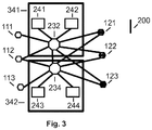
- Figure 3 shows the distribution of the hardware components of the Figure 2 to two separate modules 341 and 342.
- Each of the two modules has, for example, a processing capacity which is sufficient to carry out the safety-critical functions in accordance with the passive allocation plans PAP-1 and PAP-2 in Table 1.
- the distribution of the hardware configuration of the Figure 2 on two units, which are installed in separate locations, ensures that even after mechanical damage to one unit, for example in the event of an accident, the functional second unit can continue to perform the safety-related functions.
- one of the node computers for example the node computer 244 in, is required Figure 2 , supports a wireless connection to external computers. Accordingly, it can be determined that a security firewall is installed in this node computer.
- a security firewall is a SEZSWK of a distributed computer system that checks whether incoming and outgoing messages from a system meet specified security conditions (security assertions) .
- the security assertions can be formulated in the form of a special security markup language, eg SAML [Cam15].
- the present invention enables, among other things, a large distributed computer system to be expanded on-line, ie during operation. For this purpose, a new version of a global allocation plan (GAP) with expanded or new EZSWK must be created.
- GAP global allocation plan
- shadow TTVMs are a TTVM that is on an existing or new node computer for executing an EZSWK is running and is supplied with the input data of the current process, the output data of which, however, is not sent to the current process but to a test console.
- additional intelligent sensors can be set up to supply the EZSWK executing on the shade TTVM. As soon as the new EZSWK have been sufficiently tested, the test operation phase is completed.
- the phase of the switchover the existing GAP is replaced by the new version of the GAP at the next global restart point and the calculated output data of the new version of the GAP are passed on to the running process.
- shadow TTVM for the existing EZSWK are set up and tested on a new hardware generation .
- the new GAP is activated at the next global restart point, whereby the new GAP switches off the old hardware components and sends the results of the EZSWK running on the new hardware generation to the process.
Landscapes
- Engineering & Computer Science (AREA)
- Theoretical Computer Science (AREA)
- Physics & Mathematics (AREA)
- General Physics & Mathematics (AREA)
- Quality & Reliability (AREA)
- General Engineering & Computer Science (AREA)
- Automation & Control Theory (AREA)
- Computer Networks & Wireless Communication (AREA)
- Signal Processing (AREA)
- Health & Medical Sciences (AREA)
- Computing Systems (AREA)
- General Health & Medical Sciences (AREA)
- Medical Informatics (AREA)
- Hardware Redundancy (AREA)
- Debugging And Monitoring (AREA)
Claims (14)
- Système d'ordinateur exploité en temps réel réparti tolérant aux pannes d'une installation physique, notamment d'une machine ou d'un véhicule automobile, qui comprend les composants suivants :- un ordinateur de jonction (241, 242, 243, 244),- des unités de répartition (232, 234),- des capteurs intelligents (111, 112, 113), ainsi que des- actionneurs intelligents (121, 122, 123),
sachant que ces composants ont accès à un temps global de précision connue et, sachant que les ordinateurs de jonction, les capteurs intelligents et les actionneurs intelligents échangent des messages temporisés périodiques et des messages pilotés par événement par le biais des unités de répartition, sachant que des fonctions, notamment toutes les fonctions du logiciel d'utilisateur sont contenues dans des composants de logiciel en temps réel (CLTR) et le transfert de données temporisé périodique entre les CLTR est prédéfini, et
sachant que dans les plans d'allocation locaux actifs pour chaque CLTR- l'attribution du CLTR à une machine virtuelle à déclenchement temporisé (MVDT) d'un ordinateur de jonction- les paramètres suivants de la MVDT∘ moment de début et moment de fin d'un intervalle de service (IS),∘ zones de mémoire pour les calculs du CLTR,∘ code exécutable du CLTR∘ les programmes pour une communication temporisée de ce CLTRSont prédéfinis et sachant que dans les plans d'allocations locaux actifs pour chaque unité de répartition, les programmes pour la communication temporisée sont contenus dans cette unité de répartition et sachant qu'il existe un plan d'allocation global à partir de la somme des plans d'allocation locaux harmonisés l'un par rapport à l'autre de tous les CLTR et de toutes les unités de répartition du logiciel d'utilisateur,
et sachant qu'un composant d'écran de contrôle reçoit périodiquement une copie des messages des ordinateurs de jonction pour constater un état de fonctionnement actuel des ordinateurs de jonction,
caractérisé en ce qu'
après la défaillance permanente d'un ou de plusieurs CLTR, le composant de l'écran de contrôle active un plan d'allocation local passif, qui prédéfinit l'allocation du CLTR et l'alimentation en données de ceux-ci sur les MVDT nouvellement installées sur les ordinateurs de jonction continuant à fonctionner,
et sachant que les CLTR parviennent à exécution à un moment de redémarrage périodique prévu correspondant au plan d'allocation global passif sélectionné sur les MVDT nouvellement configurées et sachant qu'un moment de redémarrage d'un CLTR se situe dans un intervalle d'état de base revenant périodiquement, sachant que l'intervalle d'état de base est intervalle entre la fin d'un IS et le début d'un cadre suivant et sachant qu'à priori un moment de redémarrage global périodique dans un intervalle d'état de base global, intervalle de temps de base pendant lequel tous les CLTR et toutes les unités de répartition se maintiennent dans leur état de base. - Système d'ordinateur exploité en temps réel selon la revendication 1, caractérisé en ce que le paramètre IS d'un intervalle IS dans un plan d'allocation dépend de la productivité de chaque ordinateur de jonction, sur lequel une machine virtuelle à déclenchement temporisé (MVDT) pour un composant de logiciel en temps réel (CLTR) est installée et où ce paramètre IS est à priori prédéfini.
- Système d'ordinateur exploité en temps réel selon la revendication 1 ou 2, caractérisé en ce qu'un plan d'allocation local actif est à priori présent dans chaque ordinateur de jonction et chaque unité de répartition et au moins un plan d'allocation local passif peut être ou est mémorisé de préférence dans chaque ordinateur de jonction et chaque unité de répartition.
- Système d'ordinateur exploité en temps réel selon l'une quelconque des revendications 1 à 3, caractérisé en ce qu'un nouveau plan d'allocation passif et calculé pendant le fonctionnement et est chargé dans un ordinateur de jonction ou unité de répartition.
- Système d'ordinateur exploité en temps réel selon l'une quelconque des revendications 1 à 4, caractérisé en ce que le composant d'écran de contrôle reçoit du CLTR avant la fin de chaque cycle d'état de base, un message avec l'état de base d'un CLTR et sachant par exemple que le composant d'écran de contrôle (135) envoie, après la défaillance d'un CLTR, l'état de base dernièrement reçu de ce CLTR au CLTR redémarrant.
- Système d'ordinateur exploité en temps réel selon l'une quelconque des revendications 1 à 5, caractérisé en ce que le composant d'écran de contrôle sélectionne un plan d'allocation global passif après une défaillance permanente d'un ordinateur de jonction et alloue après l'allocation de composants de logiciel en temps réel critiques pour la sécurité aux nouvelles MVDT les composants de logiciel en temps réel (CLTR) défaillants non importants du point de vue sécurité, selon le principe du meilleur effort, aux MVDT, qui peuvent être agencées sur les ordinateurs de jonction fonctionnant restants.
- Système d'ordinateur exploité en temps réel selon l'une quelconque des revendications 1 à 6, caractérisé en ce que dans le cas où une hypothèse de panne prédéfinit la propriété de sécurité positive d'un ordinateur de jonction, une redondance active est réalisée avec le même CLTR grâce à l'activation simultanée de deux MVDT indépendantes, sachant que les récepteurs des messages continuent, dès qu'un des messages temporisés est reçu par ces deux MVDT.
- Système d'ordinateur exploité en temps réel selon l'une quelconque des revendications 1 à 6, caractérisé en ce que dans le cas où l'hypothèse de panne ne prédéfinit pas la propriété de sécurité positive d'un ordinateur de jonction, une redondance active est réalisée avec le même CLTR grâce à l'activation simultanée de trois MVDT indépendantes, sachant que les récepteurs des messages continuent, dès que deux des trois messages temporisés reçus contiennent des résultats égaux à un bit.
- Système d'ordinateur exploité en temps réel selon l'une quelconque des revendications 1 à 6, caractérisé en ce que dans le cas où l'hypothèse de panne ne prédéfinit pas la propriété de sécurité positive d'un ordinateur de jonction, la propriété des sécurité positive est réalisée avec le même CLTR important du point de vue sécurité, grâce à l'activation simultanée de deux MVDT indépendantes, sachant que les récepteurs des messages attendent jusqu'à ce que les deux messages temporisés soient arrivés et rejettent le résultat, au cas où les résultats ne sont pas égaux à un bit dans les deux messages temporisés arrivés.
- Système d'ordinateur exploité en temps réel selon l'une quelconque des revendications 1 à 9, caractérisé en ce que les capteurs intelligents, qui sont connectés aux deux unités de répartition, envoient respectivement deux copies d'un message temporisé simultanément par le biais de deux canaux de communication indépendants (200) aux unités de répartition pour poursuivre la répartition et sachant que le récepteur définitif de ce message rejette l'autre copie dès qu'il a reçu une copie correcte du point de vue syntaxique.
- Système d'ordinateur exploité en temps réel selon l'une quelconque des revendications 1 à 10, caractérisé en ce que dans un fonctionnement d'essai de nouveaux CLTR élargis sont installés parallèlement aux CLTR existants à l'ombre de la MVDT et sont alimentés avec les données d'entrée courantes du processus, sachant que les données de sortie du nouveau CLTR ne sont pas connectées dans le processus existant.
- Système d'ordinateur exploité en temps réel selon l'une quelconque des revendications 1 à 11, caractérisé en ce qu'au moins un ordinateur de jonction de réserve est présent pour prendre en charge les fonctions d'un ordinateur de jonction en panne.
- Système d'ordinateur exploité en temps réel selon l'une quelconque des revendications 1 à 12, caractérisé en ce que l'ordinateur de jonction et les unités de répartition sont répartis sur deux unités modulaires séparées, notamment séparées dans l'espace.
- Système d'ordinateur exploité en temps réel selon l'une quelconque des revendications 1 à 13, caractérisé en ce qu'un ordinateur de jonction, qui réalise une liaison sans fil avec des ordinateurs externes, contient un pare-feu de sécurité
Applications Claiming Priority (1)
| Application Number | Priority Date | Filing Date | Title |
|---|---|---|---|
| AT501422016 | 2016-02-26 |
Publications (2)
| Publication Number | Publication Date |
|---|---|
| EP3211533A1 EP3211533A1 (fr) | 2017-08-30 |
| EP3211533B1 true EP3211533B1 (fr) | 2020-01-08 |
Family
ID=58692268
Family Applications (1)
| Application Number | Title | Priority Date | Filing Date |
|---|---|---|---|
| EP17157802.4A Active EP3211533B1 (fr) | 2016-02-26 | 2017-02-24 | Architecture de système tolérant aux pannes destinée à commander une installation physique, en particulier une machine ou un véhicule automobile |
Country Status (2)
| Country | Link |
|---|---|
| US (1) | US10324797B2 (fr) |
| EP (1) | EP3211533B1 (fr) |
Cited By (1)
| Publication number | Priority date | Publication date | Assignee | Title |
|---|---|---|---|---|
| CN109542050A (zh) * | 2017-09-22 | 2019-03-29 | 横河电机株式会社 | 基于在开放式过程自动化系统中使用的分布式控制节点提高过程可靠性的方法 |
Families Citing this family (7)
| Publication number | Priority date | Publication date | Assignee | Title |
|---|---|---|---|---|
| EP3467598B1 (fr) * | 2017-10-04 | 2021-09-29 | TTTech Computertechnik AG | Procédé et appareil de détermination de la durée d'un créneau dans un système de commande à déclenchement temporel |
| EP3565186B1 (fr) * | 2018-05-02 | 2021-06-30 | TTTech Computertechnik AG | Dispositif et réseau pour communiquer de manière fiable dans un réseau |
| US10834434B2 (en) * | 2018-12-28 | 2020-11-10 | Intel Corporation | Methods and apparatus to reduce audio streaming latency between audio and Gigabit Ethernet subsystems |
| DE102020203420B4 (de) * | 2020-01-15 | 2021-11-04 | Volkswagen Aktiengesellschaft | Verfahren und Vorrichtung zum Rekonfigurieren eines automatisiert fahrenden Fahrzeugs in einem Fehlerfall |
| EP3902206B1 (fr) * | 2020-04-21 | 2022-02-16 | TTTech Computertechnik Aktiengesellschaft | Unité de distribution tolérante aux erreurs et procédé de fourniture d'un temps mondial tolérant aux erreurs |
| CN112231134B (zh) * | 2020-10-28 | 2023-08-08 | 地平线(上海)人工智能技术有限公司 | 神经网络处理器的故障处理方法及装置、设备、存储介质 |
| CN113985763A (zh) * | 2021-10-12 | 2022-01-28 | 江苏清盐智能科技有限公司 | 无人战车控制系统时间触发以太网络架构 |
Family Cites Families (7)
| Publication number | Priority date | Publication date | Assignee | Title |
|---|---|---|---|---|
| US6983393B2 (en) * | 2002-12-11 | 2006-01-03 | National Instruments Corporation | Deterministically handling asynchronous events in a time triggered system |
| WO2004059505A1 (fr) * | 2002-12-17 | 2004-07-15 | Systemauto | Systeme, logique et progiciel de partage de l'information dans une architecture distribuee |
| JP5362668B2 (ja) * | 2010-09-16 | 2013-12-11 | 日立オートモティブシステムズ株式会社 | 車内データ中継装置 |
| DE112012000946T5 (de) | 2011-02-22 | 2013-11-21 | Fts Computertechnik Gmbh | Versehsagbares Rechnen in virtualisierten verteilten Computersystemen basierend auf der Partitionierung von Rechenleistung und Kommunikationsleistung |
| AT512665B1 (de) * | 2012-03-20 | 2013-12-15 | Fts Computertechnik Gmbh | Verfahren und Apparat zur Bildung von Software Fault Containment Units in einem verteilten Echtzeitsystem |
| AT514444A2 (de) | 2013-06-24 | 2015-01-15 | Fts Computertechnik Gmbh | Verfahren und Vorrichtung zur zeitrichtigen Datenübergabe an die zyklischen Tasks in einem verteilten Echtzeitsystem |
| US10019292B2 (en) * | 2015-12-02 | 2018-07-10 | Fts Computertechnik Gmbh | Method for executing a comprehensive real-time computer application by exchanging time-triggered messages among real-time software components |
-
2017
- 2017-02-23 US US15/440,449 patent/US10324797B2/en active Active
- 2017-02-24 EP EP17157802.4A patent/EP3211533B1/fr active Active
Non-Patent Citations (1)
| Title |
|---|
| None * |
Cited By (2)
| Publication number | Priority date | Publication date | Assignee | Title |
|---|---|---|---|---|
| CN109542050A (zh) * | 2017-09-22 | 2019-03-29 | 横河电机株式会社 | 基于在开放式过程自动化系统中使用的分布式控制节点提高过程可靠性的方法 |
| CN109542050B (zh) * | 2017-09-22 | 2022-04-29 | 横河电机株式会社 | 用于管理工厂设施的系统和方法 |
Also Published As
| Publication number | Publication date |
|---|---|
| EP3211533A1 (fr) | 2017-08-30 |
| US20170249214A1 (en) | 2017-08-31 |
| US10324797B2 (en) | 2019-06-18 |
Similar Documents
| Publication | Publication Date | Title |
|---|---|---|
| EP3211533B1 (fr) | Architecture de système tolérant aux pannes destinée à commander une installation physique, en particulier une machine ou un véhicule automobile | |
| EP2972607B1 (fr) | Procédé de traitement d'erreurs dans une unité de commande centrale et unité de commande | |
| EP2235628B1 (fr) | Dispositif de commande d'un véhicule à moteur | |
| DE2908316C2 (de) | Modular aufgebaute Multiprozessor-Datenverarbeitungsanlage | |
| DE102017106087A1 (de) | Fehlertoleranz-muster und schaltprotokoll für mehrere hot- und cold-standby-redundanzen | |
| DE102017218395A1 (de) | Verfahren zur fehlerrobusten Regelung von hochautomatisierten Fahrzeugen | |
| EP4359933A1 (fr) | Dispositif de commande et système d'assistance pour un véhicule | |
| DE102012003242A1 (de) | Verfahren zum ausfallsicheren Betreiben eines Prozesssteuersystems mit redundanten Steuereinrichtungen | |
| WO2008040641A2 (fr) | Procédé et dispositif de gestion des pannes | |
| EP3176696A1 (fr) | Procédé de réalisation et d'exécution d'une application complexe en temps réel | |
| DE102019202527A1 (de) | Sicherheitssystem und Verfahren zum Betreiben eines Sicherheitssystems | |
| EP3444682A1 (fr) | Procédé d'accouplement assisté par ordinateur d'un module de traitement dans un système technique modulaire et système technique modulaire | |
| EP2732347A1 (fr) | Procédé et système de répartition dynamique de fonctions de programme dans des systèmes de commande répartis | |
| DE102015218898A1 (de) | Verfahren zur redundanten Verarbeitung von Daten | |
| EP4420002A1 (fr) | Réseau de traitement de données destiné à effectuer un traitement de données | |
| DE102012212680A1 (de) | Verfahren und System zur fehlertoleranten Steuerung von Stellgliedern für eine begrenzte Zeit auf der Grundlage von vorberechneten Werten | |
| DE102020107751A1 (de) | Verfahren zur Arbitrierung von Signalen von Steuergeräten in einem redundanten System für autonomes Fahren | |
| EP4390577A1 (fr) | Surveillance d'au moins une machine | |
| WO2015124320A1 (fr) | Commande à programme enregistré dynamique servant à émuler un appareil de commande | |
| EP3111600B1 (fr) | Procédé et réseau d'ordinateurs pour la transmission de messages | |
| EP4068014A1 (fr) | Solution d'automatisation en nuage hautement disponible à temps de transmission optimisés | |
| WO2022084176A1 (fr) | Réseau de traitement de données destiné à effectuer un traitement de données | |
| EP4211525B1 (fr) | Dispositif et procédé permettant de générer et transmettre des instructions de commande pour un véhicule automobile circulant en mode automatisé | |
| DE102021210077B4 (de) | Computerimplementiertes Verfahren und Steuervorrichtung zur Steuerung einer Einheit eines Automotivesystems | |
| EP4530758B1 (fr) | Surveillance d'au moins une machine |
Legal Events
| Date | Code | Title | Description |
|---|---|---|---|
| PUAI | Public reference made under article 153(3) epc to a published international application that has entered the european phase |
Free format text: ORIGINAL CODE: 0009012 |
|
| STAA | Information on the status of an ep patent application or granted ep patent |
Free format text: STATUS: THE APPLICATION HAS BEEN PUBLISHED |
|
| AK | Designated contracting states |
Kind code of ref document: A1 Designated state(s): AL AT BE BG CH CY CZ DE DK EE ES FI FR GB GR HR HU IE IS IT LI LT LU LV MC MK MT NL NO PL PT RO RS SE SI SK SM TR |
|
| AX | Request for extension of the european patent |
Extension state: BA ME |
|
| STAA | Information on the status of an ep patent application or granted ep patent |
Free format text: STATUS: REQUEST FOR EXAMINATION WAS MADE |
|
| 17P | Request for examination filed |
Effective date: 20180228 |
|
| RBV | Designated contracting states (corrected) |
Designated state(s): AL AT BE BG CH CY CZ DE DK EE ES FI FR GB GR HR HU IE IS IT LI LT LU LV MC MK MT NL NO PL PT RO RS SE SI SK SM TR |
|
| RAP1 | Party data changed (applicant data changed or rights of an application transferred) |
Owner name: TTTECH COMPUTERTECHNIK AG |
|
| STAA | Information on the status of an ep patent application or granted ep patent |
Free format text: STATUS: EXAMINATION IS IN PROGRESS |
|
| 17Q | First examination report despatched |
Effective date: 20190313 |
|
| RAP1 | Party data changed (applicant data changed or rights of an application transferred) |
Owner name: TTTECH AUTO AG |
|
| GRAP | Despatch of communication of intention to grant a patent |
Free format text: ORIGINAL CODE: EPIDOSNIGR1 |
|
| STAA | Information on the status of an ep patent application or granted ep patent |
Free format text: STATUS: GRANT OF PATENT IS INTENDED |
|
| RIC1 | Information provided on ipc code assigned before grant |
Ipc: G06F 11/16 20060101ALN20190718BHEP Ipc: G05B 19/042 20060101ALI20190718BHEP Ipc: G06F 11/20 20060101ALI20190718BHEP Ipc: G06F 11/18 20060101ALN20190718BHEP Ipc: G06F 11/14 20060101AFI20190718BHEP |
|
| INTG | Intention to grant announced |
Effective date: 20190820 |
|
| GRAS | Grant fee paid |
Free format text: ORIGINAL CODE: EPIDOSNIGR3 |
|
| GRAA | (expected) grant |
Free format text: ORIGINAL CODE: 0009210 |
|
| STAA | Information on the status of an ep patent application or granted ep patent |
Free format text: STATUS: THE PATENT HAS BEEN GRANTED |
|
| AK | Designated contracting states |
Kind code of ref document: B1 Designated state(s): AL AT BE BG CH CY CZ DE DK EE ES FI FR GB GR HR HU IE IS IT LI LT LU LV MC MK MT NL NO PL PT RO RS SE SI SK SM TR |
|
| REG | Reference to a national code |
Ref country code: GB Ref legal event code: FG4D Free format text: NOT ENGLISH |
|
| REG | Reference to a national code |
Ref country code: CH Ref legal event code: EP |
|
| REG | Reference to a national code |
Ref country code: DE Ref legal event code: R096 Ref document number: 502017003410 Country of ref document: DE |
|
| REG | Reference to a national code |
Ref country code: IE Ref legal event code: FG4D Free format text: LANGUAGE OF EP DOCUMENT: GERMAN |
|
| REG | Reference to a national code |
Ref country code: AT Ref legal event code: REF Ref document number: 1223542 Country of ref document: AT Kind code of ref document: T Effective date: 20200215 |
|
| REG | Reference to a national code |
Ref country code: NL Ref legal event code: MP Effective date: 20200108 |
|
| REG | Reference to a national code |
Ref country code: LT Ref legal event code: MG4D |
|
| PG25 | Lapsed in a contracting state [announced via postgrant information from national office to epo] |
Ref country code: PT Free format text: LAPSE BECAUSE OF FAILURE TO SUBMIT A TRANSLATION OF THE DESCRIPTION OR TO PAY THE FEE WITHIN THE PRESCRIBED TIME-LIMIT Effective date: 20200531 Ref country code: NL Free format text: LAPSE BECAUSE OF FAILURE TO SUBMIT A TRANSLATION OF THE DESCRIPTION OR TO PAY THE FEE WITHIN THE PRESCRIBED TIME-LIMIT Effective date: 20200108 Ref country code: LT Free format text: LAPSE BECAUSE OF FAILURE TO SUBMIT A TRANSLATION OF THE DESCRIPTION OR TO PAY THE FEE WITHIN THE PRESCRIBED TIME-LIMIT Effective date: 20200108 Ref country code: NO Free format text: LAPSE BECAUSE OF FAILURE TO SUBMIT A TRANSLATION OF THE DESCRIPTION OR TO PAY THE FEE WITHIN THE PRESCRIBED TIME-LIMIT Effective date: 20200408 Ref country code: FI Free format text: LAPSE BECAUSE OF FAILURE TO SUBMIT A TRANSLATION OF THE DESCRIPTION OR TO PAY THE FEE WITHIN THE PRESCRIBED TIME-LIMIT Effective date: 20200108 Ref country code: RS Free format text: LAPSE BECAUSE OF FAILURE TO SUBMIT A TRANSLATION OF THE DESCRIPTION OR TO PAY THE FEE WITHIN THE PRESCRIBED TIME-LIMIT Effective date: 20200108 |
|
| PG25 | Lapsed in a contracting state [announced via postgrant information from national office to epo] |
Ref country code: GR Free format text: LAPSE BECAUSE OF FAILURE TO SUBMIT A TRANSLATION OF THE DESCRIPTION OR TO PAY THE FEE WITHIN THE PRESCRIBED TIME-LIMIT Effective date: 20200409 Ref country code: HR Free format text: LAPSE BECAUSE OF FAILURE TO SUBMIT A TRANSLATION OF THE DESCRIPTION OR TO PAY THE FEE WITHIN THE PRESCRIBED TIME-LIMIT Effective date: 20200108 Ref country code: SE Free format text: LAPSE BECAUSE OF FAILURE TO SUBMIT A TRANSLATION OF THE DESCRIPTION OR TO PAY THE FEE WITHIN THE PRESCRIBED TIME-LIMIT Effective date: 20200108 Ref country code: LV Free format text: LAPSE BECAUSE OF FAILURE TO SUBMIT A TRANSLATION OF THE DESCRIPTION OR TO PAY THE FEE WITHIN THE PRESCRIBED TIME-LIMIT Effective date: 20200108 Ref country code: BG Free format text: LAPSE BECAUSE OF FAILURE TO SUBMIT A TRANSLATION OF THE DESCRIPTION OR TO PAY THE FEE WITHIN THE PRESCRIBED TIME-LIMIT Effective date: 20200408 Ref country code: IS Free format text: LAPSE BECAUSE OF FAILURE TO SUBMIT A TRANSLATION OF THE DESCRIPTION OR TO PAY THE FEE WITHIN THE PRESCRIBED TIME-LIMIT Effective date: 20200508 |
|
| REG | Reference to a national code |
Ref country code: CH Ref legal event code: PL |
|
| REG | Reference to a national code |
Ref country code: DE Ref legal event code: R097 Ref document number: 502017003410 Country of ref document: DE |
|
| REG | Reference to a national code |
Ref country code: BE Ref legal event code: MM Effective date: 20200229 |
|
| PG25 | Lapsed in a contracting state [announced via postgrant information from national office to epo] |
Ref country code: DK Free format text: LAPSE BECAUSE OF FAILURE TO SUBMIT A TRANSLATION OF THE DESCRIPTION OR TO PAY THE FEE WITHIN THE PRESCRIBED TIME-LIMIT Effective date: 20200108 Ref country code: SM Free format text: LAPSE BECAUSE OF FAILURE TO SUBMIT A TRANSLATION OF THE DESCRIPTION OR TO PAY THE FEE WITHIN THE PRESCRIBED TIME-LIMIT Effective date: 20200108 Ref country code: EE Free format text: LAPSE BECAUSE OF FAILURE TO SUBMIT A TRANSLATION OF THE DESCRIPTION OR TO PAY THE FEE WITHIN THE PRESCRIBED TIME-LIMIT Effective date: 20200108 Ref country code: LU Free format text: LAPSE BECAUSE OF NON-PAYMENT OF DUE FEES Effective date: 20200224 Ref country code: RO Free format text: LAPSE BECAUSE OF FAILURE TO SUBMIT A TRANSLATION OF THE DESCRIPTION OR TO PAY THE FEE WITHIN THE PRESCRIBED TIME-LIMIT Effective date: 20200108 Ref country code: CZ Free format text: LAPSE BECAUSE OF FAILURE TO SUBMIT A TRANSLATION OF THE DESCRIPTION OR TO PAY THE FEE WITHIN THE PRESCRIBED TIME-LIMIT Effective date: 20200108 Ref country code: SK Free format text: LAPSE BECAUSE OF FAILURE TO SUBMIT A TRANSLATION OF THE DESCRIPTION OR TO PAY THE FEE WITHIN THE PRESCRIBED TIME-LIMIT Effective date: 20200108 Ref country code: ES Free format text: LAPSE BECAUSE OF FAILURE TO SUBMIT A TRANSLATION OF THE DESCRIPTION OR TO PAY THE FEE WITHIN THE PRESCRIBED TIME-LIMIT Effective date: 20200108 Ref country code: MC Free format text: LAPSE BECAUSE OF FAILURE TO SUBMIT A TRANSLATION OF THE DESCRIPTION OR TO PAY THE FEE WITHIN THE PRESCRIBED TIME-LIMIT Effective date: 20200108 |
|
| PLBE | No opposition filed within time limit |
Free format text: ORIGINAL CODE: 0009261 |
|
| STAA | Information on the status of an ep patent application or granted ep patent |
Free format text: STATUS: NO OPPOSITION FILED WITHIN TIME LIMIT |
|
| PG25 | Lapsed in a contracting state [announced via postgrant information from national office to epo] |
Ref country code: LI Free format text: LAPSE BECAUSE OF NON-PAYMENT OF DUE FEES Effective date: 20200229 Ref country code: CH Free format text: LAPSE BECAUSE OF NON-PAYMENT OF DUE FEES Effective date: 20200229 |
|
| 26N | No opposition filed |
Effective date: 20201009 |
|
| PG25 | Lapsed in a contracting state [announced via postgrant information from national office to epo] |
Ref country code: IT Free format text: LAPSE BECAUSE OF FAILURE TO SUBMIT A TRANSLATION OF THE DESCRIPTION OR TO PAY THE FEE WITHIN THE PRESCRIBED TIME-LIMIT Effective date: 20200108 Ref country code: IE Free format text: LAPSE BECAUSE OF NON-PAYMENT OF DUE FEES Effective date: 20200224 |
|
| PG25 | Lapsed in a contracting state [announced via postgrant information from national office to epo] |
Ref country code: SI Free format text: LAPSE BECAUSE OF FAILURE TO SUBMIT A TRANSLATION OF THE DESCRIPTION OR TO PAY THE FEE WITHIN THE PRESCRIBED TIME-LIMIT Effective date: 20200108 Ref country code: PL Free format text: LAPSE BECAUSE OF FAILURE TO SUBMIT A TRANSLATION OF THE DESCRIPTION OR TO PAY THE FEE WITHIN THE PRESCRIBED TIME-LIMIT Effective date: 20200108 Ref country code: BE Free format text: LAPSE BECAUSE OF NON-PAYMENT OF DUE FEES Effective date: 20200229 |
|
| PG25 | Lapsed in a contracting state [announced via postgrant information from national office to epo] |
Ref country code: TR Free format text: LAPSE BECAUSE OF FAILURE TO SUBMIT A TRANSLATION OF THE DESCRIPTION OR TO PAY THE FEE WITHIN THE PRESCRIBED TIME-LIMIT Effective date: 20200108 Ref country code: MT Free format text: LAPSE BECAUSE OF FAILURE TO SUBMIT A TRANSLATION OF THE DESCRIPTION OR TO PAY THE FEE WITHIN THE PRESCRIBED TIME-LIMIT Effective date: 20200108 Ref country code: CY Free format text: LAPSE BECAUSE OF FAILURE TO SUBMIT A TRANSLATION OF THE DESCRIPTION OR TO PAY THE FEE WITHIN THE PRESCRIBED TIME-LIMIT Effective date: 20200108 |
|
| PG25 | Lapsed in a contracting state [announced via postgrant information from national office to epo] |
Ref country code: MK Free format text: LAPSE BECAUSE OF FAILURE TO SUBMIT A TRANSLATION OF THE DESCRIPTION OR TO PAY THE FEE WITHIN THE PRESCRIBED TIME-LIMIT Effective date: 20200108 Ref country code: AL Free format text: LAPSE BECAUSE OF FAILURE TO SUBMIT A TRANSLATION OF THE DESCRIPTION OR TO PAY THE FEE WITHIN THE PRESCRIBED TIME-LIMIT Effective date: 20200108 |
|
| REG | Reference to a national code |
Ref country code: AT Ref legal event code: MM01 Ref document number: 1223542 Country of ref document: AT Kind code of ref document: T Effective date: 20220224 |
|
| PG25 | Lapsed in a contracting state [announced via postgrant information from national office to epo] |
Ref country code: AT Free format text: LAPSE BECAUSE OF NON-PAYMENT OF DUE FEES Effective date: 20220224 |
|
| PGFP | Annual fee paid to national office [announced via postgrant information from national office to epo] |
Ref country code: GB Payment date: 20260121 Year of fee payment: 10 |
|
| PGFP | Annual fee paid to national office [announced via postgrant information from national office to epo] |
Ref country code: DE Payment date: 20260121 Year of fee payment: 10 |
|
| PGFP | Annual fee paid to national office [announced via postgrant information from national office to epo] |
Ref country code: FR Payment date: 20260121 Year of fee payment: 10 |