EP3211606A2 - Batterieüberwachungsmodul - Google Patents
Batterieüberwachungsmodul Download PDFInfo
- Publication number
- EP3211606A2 EP3211606A2 EP17158078.0A EP17158078A EP3211606A2 EP 3211606 A2 EP3211606 A2 EP 3211606A2 EP 17158078 A EP17158078 A EP 17158078A EP 3211606 A2 EP3211606 A2 EP 3211606A2
- Authority
- EP
- European Patent Office
- Prior art keywords
- monitoring module
- operating parameters
- radio communication
- ignition switch
- starter battery
- Prior art date
- Legal status (The legal status is an assumption and is not a legal conclusion. Google has not performed a legal analysis and makes no representation as to the accuracy of the status listed.)
- Granted
Links
Images


Classifications
-
- G—PHYSICS
- G07—CHECKING-DEVICES
- G07C—TIME OR ATTENDANCE REGISTERS; REGISTERING OR INDICATING THE WORKING OF MACHINES; GENERATING RANDOM NUMBERS; VOTING OR LOTTERY APPARATUS; ARRANGEMENTS, SYSTEMS OR APPARATUS FOR CHECKING NOT PROVIDED FOR ELSEWHERE
- G07C5/00—Registering or indicating the working of vehicles
- G07C5/008—Registering or indicating the working of vehicles communicating information to a remotely located station
-
- G—PHYSICS
- G01—MEASURING; TESTING
- G01R—MEASURING ELECTRIC VARIABLES; MEASURING MAGNETIC VARIABLES
- G01R31/00—Arrangements for testing electric properties; Arrangements for locating electric faults; Arrangements for electrical testing characterised by what is being tested not provided for elsewhere
- G01R31/36—Arrangements for testing, measuring or monitoring the electrical condition of accumulators or electric batteries, e.g. capacity or state of charge [SoC]
- G01R31/371—Arrangements for testing, measuring or monitoring the electrical condition of accumulators or electric batteries, e.g. capacity or state of charge [SoC] with remote indication, e.g. on external chargers
-
- G—PHYSICS
- G01—MEASURING; TESTING
- G01R—MEASURING ELECTRIC VARIABLES; MEASURING MAGNETIC VARIABLES
- G01R31/00—Arrangements for testing electric properties; Arrangements for locating electric faults; Arrangements for electrical testing characterised by what is being tested not provided for elsewhere
- G01R31/36—Arrangements for testing, measuring or monitoring the electrical condition of accumulators or electric batteries, e.g. capacity or state of charge [SoC]
- G01R31/382—Arrangements for monitoring battery or accumulator variables, e.g. SoC
- G01R31/3835—Arrangements for monitoring battery or accumulator variables, e.g. SoC involving only voltage measurements
-
- G—PHYSICS
- G01—MEASURING; TESTING
- G01R—MEASURING ELECTRIC VARIABLES; MEASURING MAGNETIC VARIABLES
- G01R31/00—Arrangements for testing electric properties; Arrangements for locating electric faults; Arrangements for electrical testing characterised by what is being tested not provided for elsewhere
- G01R31/005—Testing of electric installations on transport means
- G01R31/006—Testing of electric installations on transport means on road vehicles, e.g. automobiles or trucks
- G01R31/007—Testing of electric installations on transport means on road vehicles, e.g. automobiles or trucks using microprocessors or computers
-
- G—PHYSICS
- G07—CHECKING-DEVICES
- G07C—TIME OR ATTENDANCE REGISTERS; REGISTERING OR INDICATING THE WORKING OF MACHINES; GENERATING RANDOM NUMBERS; VOTING OR LOTTERY APPARATUS; ARRANGEMENTS, SYSTEMS OR APPARATUS FOR CHECKING NOT PROVIDED FOR ELSEWHERE
- G07C2205/00—Indexing scheme relating to group G07C5/00
- G07C2205/02—Indexing scheme relating to group G07C5/00 using a vehicle scan tool
Definitions
- the invention relates to a monitoring module for detecting operating parameters of a drive machine, in particular a construction machine, which has a starter battery and can be started via an ignition switch.
- BCUs Battery Control Units
- Such control modules are usually networked with a large number of sensors and switches with the traction battery and a vehicle control system.
- Such modules are thus a solid, integrated component of a complex control system, which would not be functional without a corresponding battery monitoring module.
- the object of the present invention is to provide a solution for the Simple monitoring of a voltage of a starter battery, which is sometimes not recharged for a long time.
- This problem arises, for example, in a fleet of construction machinery, which may be longer use breaks between several uses of construction equipment, for example, seasonal reasons.
- Task is to be able to minimize due to battery failure maintenance costs and costs, for example, by early detection of voltage drops. It is also the task that also and especially in use scenarios with many simultaneously to be monitored engines monitoring with little staff and time is possible.
- the invention relates to a monitoring module for detecting operating parameters of a prime mover, which can be started via an ignition switch, wherein the operating parameters include at least the voltage of a starter battery of the prime mover.
- the invention further relates to a smartphone application for configuring the monitoring module, an aggregation device for administration of a plurality of monitoring modules and a method for monitoring at least one operating parameter of a drive machine.
- a monitoring module for detecting operating parameters of a drive machine, in particular a construction machine, which has a starter battery and can be started via an ignition switch, wherein the operating parameters comprise at least the voltage of the starter battery of the prime mover, wherein the monitoring module for wireless transmission of the operating parameters, a radio communication device has, and wherein the monitoring module has a male or female element of a multi-pole electrical connector for connection to the prime mover, via which it is detachably connectable to the poles of the starter battery and the ignition switch.
- a connection with an ignition switch means a connection with the switchable contact of the ignition switch, so that it can be seen, for example, the voltage at the contact, whether the ignition switch is in an on state or an off state.
- the monitoring module thus offers the advantage of being connectable to the drive machine with very few, usually only three, connections whose starter battery is to be monitored.
- an embodiment of the connection as a detachable plug connection offers the advantage that the monitoring module, for example, only temporarily, i. can only be connected to the drive machine when needed.
- it has the advantage that it is very easy to remove or replace in the event of a defect. Even in a maintenance case, for example for a software update, the module can be temporarily released from the drive machine.
- a standard connector such as a standard industrial connector, a standard automotive plug-in connector or a standardized OBD connector (on-board diagnostic connector) offers the advantage of being uniform in larger quantities to be finished.
- the monitoring module as a plug element therefore has a plug contact according to a standard industrial plug, a standard automotive plug-in relay or a standard OBD connector.
- the module For the transmission of operating parameters, in particular the voltage of the starter battery, the module has a radio communication device, so that the transmission can be done wirelessly.
- This is advantageously done via WLAN according to the IEEE 802.11 standard.
- a wireless transmission of the operating parameters via a WLAN allows a transmission of data over distances, depending on the topology, up to several hundred meters.
- the range of the monitoring module is thus advantageously suitable for overcoming the distances to be bridged, for example, in a vehicle fleet of construction machines.
- the monitoring module can be operated in two operating modes, wherein the operating mode is dependent on the switching state of the ignition switch.
- the radio communication device is set up both for operation in a station mode for radio communication with an access point and for operation in an access point mode for radio communication with a station.
- a radio communication device If a radio communication device is operated in an access point mode, a radio cell is actively formed by this radio communication device. For this purpose, the radio communication device emits a "beacon" called carrier signal, through the range of which the size of the radio cell is described.
- the beacon contains information that can be used to identify the type of radio cell, the operator, etc. If the radio communication device is operated as an access point in accordance with the IEEE802.11 WLAN standard, it normally sends a so-called SSID, a service set identifier, at short, repetitive intervals via the beacon, by means of which the name of the radio network can be recognized.
- this radio communication device is a substantially passive receiving station in a radio cell, which merely establishes a (useful) data connection to a central access point if required. For this reason, the energy consumption of a radio communication device when operating in a station mode is significantly lower than in an operation in access point mode.
- the monitoring module is configured to operate in an off state of the ignition switch in the station mode and in an on state of the ignition switch in the access point mode, except for configuration parameters such as a network name.
- Such an embodiment offers the first advantage that the power consumption of the monitoring module is coupled to the switching state of the ignition switch, and thus usually of the operation of the prime mover.
- the power consumption of the monitoring module is coupled to the switching state of the ignition switch, and thus usually of the operation of the prime mover.
- the power consumption of the monitoring module is coupled to the switching state of the ignition switch, and thus usually of the operation of the prime mover.
- this embodiment provides the second advantage that manually switched on the operation of the ignition switch, a local radio network, or can be constructed by radio technology.
- This local radio network can be recognized by another, in station mode operating radio communication device, called station for short, and used to establish a connection.
- the further radio communication device may for example be a radio interface of a data acquisition terminal, with the aid of which the operating parameters are read from the monitoring device.
- the monitoring module advantageously has a control device which is set up after a change of state of the ignition switch to transmit configuration and / or operating parameters to a vorgebare radio communication device in access point mode, short access point, or a predetermined station.
- the monitoring module is set up such that the radio communication is performed according to the IEEE 802.11 (WLAN) standard and the monitoring module in the on state of the ignition switch can be connected to a WiFi-certified mobile terminal.
- WiFi IEEE 802.11
- a correspondingly certified, commercially available smartphone can be connected to the monitoring module.
- the monitoring module has a non-volatile memory for storing measured values (operating hours, no-load voltage) or a maintenance history.
- the maintenance history can contain maintenance notes, which can be transmitted to the monitoring module, for example, by a service employee using a smartphone.
- this has a control device which is configured to receive data related to the engine, in particular maintenance reports, to store and, for example, on request for the request-response principle, to send.
- the monitoring module has a measuring device for detecting the battery voltage.
- a measuring device for detecting the battery voltage This can be embodied, for example, in the form of an analog-digital converter, which digitizes the battery voltage, which in an advantageous embodiment corresponds to the supply voltage of the module.
- Values or entries stored in the memory are advantageously created in a time series, so that it is possible to trace back at which time point which values were measured or transmitted.
- the monitoring module advantageously has a timer. This is suitable for detecting the operating time, which can be determined approximately as the time duration in which the ignition switch has the on state.
- control device is advantageously configured to switch in the off state of the ignition switch in a power-down mode, the monitoring module at predetermined time intervals for the detection of operating parameters and radio communication in station mode for transmitting the operating parameters to a predetermined Radio communication device in access point mode interrupts.
- the operating parameters include the last detected operating state, in particular the last measured voltage, the previous number of operating hours and any new maintenance notes.
- control device of the monitoring module is set up to transmit configuration and / or operating parameters via an access point to a predeterminable server of a network in order to make the data accessible for further analysis.
- a smartphone application for configuring a monitoring module having the above-described features, wherein the smartphone application is designed to establish a radio communication connection with the smartphone in station mode and the monitoring module in access point mode via a smartphone and configuration and / or maintenance parameters from the smartphone to the monitoring module, or to transmit configuration and / or operating parameters from the monitoring module to the smartphone.
- a connection to the described monitoring module can be established with a commercially available smartphone.
- such an application can be used for initial configuration or commissioning of the monitoring module.
- an aggregation device for administration of a plurality of monitoring modules with the features described above, wherein the aggregation device has a memory, a network communication interface and a radio communication device, which is set up for transmission in access point mode, and has a control device that is set up receive a plurality of similar configuration and / or operating parameters from a monitoring module having the above-described features, store it in the memory and transmit it via the network communication interface.
- the aggregation device for retrieving the configuration and / or operating parameters of all monitoring modules located in range is executed at regular intervals.
- the aggregation device can be set up to store the configuration and / or operating parameters either locally, so that they are available in a retrieval by means of the smartphone application, or the aggregation device can be set up via the configuration and / or operating parameters to transmit the network communication interface to a network application.
- a network application for evaluating configuration and / or operating parameters of at least one monitoring module with prescribed features, wherein the network application is set up, configuration and / or operating parameters of a monitoring module with features described above or an aggregation device described above Receive characteristics, evaluate them time-based and signal a voltage drop.
- the network application allows all configuration and / or operating parameters, including stored maintenance reports, to be combined into one Network belonging monitoring modules to record chronologically. As a result, a time-based evaluation of the development of the configuration and / or operating parameters of a monitored engine is possible, which makes, among other things, early detection of a voltage drop.
- the application is mobile-optimized and can be used on common Internet-enabled devices (PC, laptop, tablet PC, smartphone).
- Fig. 1 shows a plurality of arrangements 1 ', 1 ", 1"', 1 "" from a prime mover and a monitoring module
- the drive machines are exemplified as construction machines.
- the prime movers on a starter battery and an ignition switch.
- the monitoring modules are detachably connected via a multi-pin electrical connector.
- the monitoring modules of the arrangements 1 ', 1 ", 1"', 1 "” have radio communication devices which are operated in a station mode STA and with which the arrangements 1 ', 1 ", 1"', 1 ", or their monitoring modules can establish a radio link for the transmission of operating parameters to another, here centrally arranged radio communication device 2.
- the further, centrally represented radio communication device 2 is operated in the access point mode AP.
- the radio communication device 2 may be part of an aggregation device or a commercially available, preferably WiFi-certified WLAN access points.
- the aggregation device or the commercially available WLAN access points have a network communication interface via which a connection 11 to the Internet 12 can be produced.
- the radio communication device 2 is part of a commercially available access point, the operating parameters of the arrangements 1 ', 1 ", 1"', 1 "" via the connection 11 to an evaluation unit (PC, laptop, Tablet PC, Smartphone) on the Internet 12 directly.
- an evaluation unit PC, laptop, Tablet PC, Smartphone
- the operating parameters collected in the aggregation device are from the devices 1 ', 1 ", 1"', 1 "" via the connection 11 collected from an evaluation unit (PC, laptop, tablet PC, smartphone), not shown here on the Internet 12 available.
- PC PC, laptop, tablet PC, smartphone
- a second arrangement 1' is represented by a drive machine and a monitoring module.
- the arrangement 1' or the radio communication device of the transmission module connected to the drive machine can alternatively be operated in the access point mode AP. This is preferably done in the case in which the ignition switch of the prime mover of the assembly 1 'is in the on state. In this state, the arrangement 1 'can be connected to a third, in station mode radio communication device 3, which may be, for example, an integral part of a smartphone.
- FIGS. 2a and 2b show the alternative operation of the arrangement 1 'in station mode, shown in FIG Fig. 2a , or in access point mode, shown in Fig. 2b ,
- Fig. 2a shows a radio communication device 2, which emits in access point mode in short, repetitive intervals a beacon, which contains an SSID, a service set identifier.
- the radio communication device 2 forms a local radio cell or a local radio network, wherein the name of the radio cell / of the radio network is recognizable on the basis of the SSID.
- the arrangement 1 ' is a subscriber of this radio network in station mode.
- the radio communication device 3 in the form of a smartphone is a subscriber to this radio network in station mode.
- Fig. 3 shows a block diagram of an embodiment of a monitoring module 1.
- the monitoring module 1 has a male or female element 5 of a multi-pole electrical connector for connection to the prime mover, so that it can be detachably connected to the poles + / - the starter battery and the ignition switch IG of the drive machine is.
- a / D analog-to-digital converter
- MEM non-volatile memory
- operating parameters such as the voltage of the starter battery can be stored.
- the stored operating parameters may also have been received via a radio communication device 4, for example in the form of maintenance notes relating to the drive machine.
- the radio communication device (RF) 4 is set up both for operation in a station mode for radio communication with an access point and for operation in an access point mode for radio communication with a station.
- the control of their respective operation is performed by a microprocessor-based controller (MCU) 10.
- MCU microprocessor-based controller
- FIGS. 4a / b show an embodiment of a monitoring module 1 in a first housing 13 with standardized automotive relay plug contacts.
- Fig. 4a shows the monitoring module 1 in a perspective view
- Fig. 4b shows a view of a corresponding socket with numbered PINs.
- the pin assignment of the socket is not uniformly standardized.
- a PIN assignment for example, be selected so that on PIN 2, the positive pole of the starter battery ("Dauerplus 30"), on PIN 4, the negative terminal of the starter battery (“mass 85”) and PIN 7 of the ignition switch ("ignition 15”) the information given in parenthesis represents the common names in motor vehicle technology.
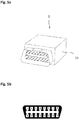
- FIGS. 5a / b show an embodiment of a monitoring module 1 in a second housing 14 with a standardized in the vehicle electrical OBD connector.
- Fig. 5a shows the monitoring module 1 in a perspective view
- Fig. 5b shows a view of a corresponding socket with numbered PINs.
- the pin assignment of the socket is only partially uniformly standardized.
- the battery voltage is usually PIN16 and the vehicle ground is PIN4.
- the condition of the ignition is with some manufacturers on PIN1.
Landscapes
- Physics & Mathematics (AREA)
- General Physics & Mathematics (AREA)
- Selective Calling Equipment (AREA)
- Secondary Cells (AREA)
- Operation Control Of Excavators (AREA)
Abstract
Description
- Die Erfindung betrifft ein Überwachungsmodul zur Erfassung von Betriebsparametern einer Antriebsmaschine, insbesondere einer Baumaschine, die eine Starterbatterie aufweist und über einen Zündschalter gestartet werden kann.
- Sie betrifft ferner eine Smartphone-Applikation zur Konfiguration des Überwachungsmoduls, eine Aggregationsvorrichtung zur Administration einer Mehrzahl von Überwachungsmodulen sowie ein Verfahren zur Überwachung zumindest eines Betriebsparameters einer Antriebsmaschine.
- Aus dem Bereich der Elektromobilität sind Batterieüberwachungsmodule als integrierte Bestandteile von Traktionsbatterien für Elektrofahrzeuge bekannt. In diesen kommen entsprechenden Steuerungsmodule, dort Battery-Control-Units, kurz BCUs genannt, zum Einsatz, welche umfangreiche Aufgaben zur optimalen Kapazitätsausnutzung, der zur Ladung der Batterie, dem Ladungsausgleich zwischen Zellen, etc. ausüben. Derartige Steuerungsmodule sind in der Regel über eine Vielzahl von Sensoren und Schaltern stark mit der Traktionsbatterie sowie einer Fahrzeugsteuerung vernetzt. Derartige Module sind somit ein fester, integrierter Bestandteil eines komplexen Steuerungssystems, welches ohne ein entsprechendes Batterieüberwachungsmodul nicht funktionsfähig wäre.
- Im Unterschied zur komplexen Überwachung und Steuerung einer Traktionsbatterie ist die Aufgabe der vorliegenden Erfindung die Angabe einer Lösung für die einfache Überwachung einer Spannung einer Starterbatterie, welche mitunter über längere Zeit nicht nachgeladen wird. Dieses Problem stellt sich beispielsweise bei einem Fuhrpark von Baumaschinen, wobei zwischen mehreren Einsätzen der Baumaschinen, beispielsweise jahreszeitlich bedingt, längere Benutzungspausen liegen können. Aufgabe ist es, durch Batterieausfall bedingte Wartungsaufwände und -kosten beispielsweise durch frühzeitige Erkennbarkeit von Spannungsabfällen minimieren zu können. Dabei ist es ferner Aufgabe, dass auch und gerade in Einsatzszenarien mit vielen gleichzeitig zu überwachenden Antriebsmaschinen die Überwachung mit geringem Personal- und Zeiteinsatz möglich ist.
- Die Lösung der Aufgabe erfolgt erfindungsgemäß durch die Merkmale der unabhängigen Ansprüche. Vorteilhafte Ausgestaltungen der Erfindung sind in den Unteransprüchen angegeben.
- Gegenstand der Erfindung ist ein Überwachungsmodul zur Erfassung von Betriebsparametern einer Antriebsmaschine, die über einen Zündschalter gestartet werden kann, wobei die Betriebsparameter zumindest die Spannung einer Starterbatterie der Antriebsmaschine umfassen. Gegenstand der Erfindung ist ferner eine Smartphone-Applikation zur Konfiguration des Überwachungsmoduls, eine Aggregationsvorrichtung zur Administration einer Mehrzahl von Überwachungsmodulen und eine Verfahren zur Überwachung zumindest eines Betriebsparameters einer Antriebsmaschine.
- Erfindungsgemäß vorgesehen ist ein Überwachungsmodul zur Erfassung von Betriebsparametern einer Antriebsmaschine, insbesondere einer Baumaschine, die eine Starterbatterie aufweist und über einen Zündschalter gestartet werden kann, wobei die Betriebsparameter zumindest die Spannung der Starterbatterie der Antriebsmaschine umfassen, wobei das Überwachungsmodul zur drahtlosen Übermittlung der Betriebsparameter eine Funkkommunikationseinrichtung aufweist, und wobei das Überwachungsmodul ein Stecker- oder Buchsen- Element einer mehrpoligen elektrischen Steckverbindung zur Verbindung mit der Antriebsmaschine aufweist, über die es lösbar mit den Polen der Starterbatterie und mit dem Zündschalter verbindbar ist.
- Dabei bedeutet eine Verbindung mit einem Zündschalter eine Verbindung mit dem schaltbaren Kontakt des Zündschalters, so dass anhand beispielsweise der Spannung an dem Kontakt erkennbar ist, ob sich der Zündschalter in einem Ein-Zustand oder einem Aus-Zustand befindet.
- Das Überwachungsmodul bietet somit den Vorteil, mit sehr wenigen, in der Regel nur drei Verbindungen mit der Antriebsmaschine verbindbar zu sein, deren Starterbatterie überwacht werden soll. Dabei bietet eine Ausführung der Verbindung als lösbare Steckverbindung den Vorteil, dass das Überwachungsmodul beispielsweise lediglich temporär, d.h. nur bei Bedarf mit der Antriebsmaschine verbunden werden kann. Des Weiteren bietet es den Vorteil, dass es im Defektfall sehr einfach zu entfernen bzw. auszutauschen ist. Auch in einem Wartungsfall, beispielsweise für ein Softwareupdate, kann das Modul temporär von der Antriebsmaschine gelöst werden. Darüber hinaus bietet eine Ausführung des Überwachungsmoduls mit einem einheitlichen Stecker, beispielsweise einem Standard-Industrie Stecker, einem Standard KFZ-Steckrelais-Stecker oder einem standardisierten OBD-Stecker (On-Board-Diagnose-Stecker) den Vorteil, dass es einheitlich in größerer Stückzahl zu fertigen ist. Darüber hinaus weisen viele Antriebsmaschinen bereits entsprechende Buchsen bzw. Kupplungen zum Anschluss eines derartigen Steckers auf, so dass in vielen Anwendungsfällen für die Verbindung des Überwachungsmoduls mit der Antriebsmaschine keine baulichen Maßnahmen erforderlich sind. Vorteilhaft weist das Überwachungsmodul als Stecker-Element daher einen Steckkontakt gemäß eines Standard-Industriesteckers, eines Standard-KFZ-Steckrelais oder eines Standard-OBD-Konnektors auf.
- Zur Übermittlung von Betriebsparametern, insbesondere der Spannung der Starterbatterie, weist das Modul eine Funkkommunikationseinrichtung auf, so dass die Übermittlung drahtlos erfolgen kann. Vorteilhaft erfolgt diese über WLAN nach dem IEEE 802.11 Standard. Eine drahtlose Übermittlung der Betriebsparameter über ein WLAN erlaubt eine Übertragung der Daten über Strecken, abhängig von der Topologie, bis zu einigen hundert Metern. Die Reichweite des Überwachungsmoduls ist damit vorteilhaft geeignet, die beispielsweise in einem Fuhrpark von Baumaschinen zu überbrückenden Distanzen zu überwinden. Vorteilhaft ist das Überwachungsmodul in zwei Betriebsmodi betreibbar, wobei der Betriebsmodus von dem Schaltzustand des Zündschalters abhängig ist. Weiterhin vorteilhaft ist die Funkkommunikationseinrichtung sowohl zum Betrieb in einem Station-Mode zur Funkkommunikation mit einem Access-Point als auch zum Betrieb in einem Access-Point-Mode zur Funkkommunikation mit einer Station eingerichtet.
- Wird eine Funkkommunikationseinrichtung in einem Access-Point Mode betrieben, so wird durch diese Funkkommunikationseinrichtung aktiv eine Funkzelle ausgebildet. Dazu sendet die Funkkommunikationseinrichtung ein "Beacon" genanntes Trägersignal aus, durch dessen Reichweite die Größe der Funkzelle beschrieben wird. Der Beacon enthält unter anderem Informationen, anhand derer die Art der Funkzelle, der Betreiber, etc. identifiziert werden können. Wird die Funkkommunikationseinrichtung als Access-Point nach dem IEEE802.11 WLAN-Standard betrieben, so versendet sie im Normalfall in kurzen, sich wiederholenden Abständen über den Beacon eine sogenannte SSID, einen Service Set Identifier, anhand dessen der Name des Funknetzes erkannt werden kann.
- Wird eine Funkkommunikationseinrichtung in einem Station Mode betrieben, so stellt diese Funkkommunikationseinrichtung eine im Wesentlichen passive Empfangs-Station in einer Funkzelle dar, die lediglich im Bedarfsfall eine (Nutz-) Datenverbindung zu einem zentralen Access-Point aufbaut. Aus diesem Grund ist der Energieverbrauch einer Funkkommunikationseinrichtung bei einem Betrieb in einem Station-Mode deutlich geringer als bei einem Betrieb im Access-Point-Mode.
- Das Überwachungsmodul ist - abgesehen von Konfigurationsparametern wie beispielsweise einem Netzwerknamen - dazu eingerichtet, in einem Aus-Zustand des Zündschalters in dem Station-Mode, und in einem Ein-Zustand des Zündschalters in dem Access-Point-Mode zu arbeiten. Eine derartige Ausführung bietet den ersten Vorteil, dass der Energieverbrauch des Überwachungsmoduls mit dem Schaltzustand des Zündschalters, und somit in der Regel von dem Betrieb der Antriebsmaschine gekoppelt ist. Bei ausgeschalteter Zündung ist der Energiebedarf der Funkkommunikationseinrichtung sehr gering, bei eingeschalteter ist er sehr viel höher. Bei eingeschalteter Zündung wird jedoch in der Regel durch den Betrieb der Antriebsmaschine zusätzliche elektrische Energie über eine Lichtmaschine erzeugt, so dass der höhere Energiebedarf der Funkkommunikationseinrichtung unerheblich ist. Zeiträume, in denen ein Zündschalter geschlossen ist, in denen die Antriebsmaschine jedoch nicht in Betrieb ist, sind in der Regel so kurz, dass sie hinsichtlich der Entladung der Starterbatterie unerheblich sind.
- Darüber hinaus bietet diese Ausgestaltung den zweiten Vorteil, dass über die Betätigung des Zündschalters manuell ein lokales Funknetz eingeschaltet, bzw. funktechnisch aufgebaut werden kann. Dieses lokale Funknetz kann von einer weiteren, im Station-Mode operierenden Funkkommunikationseinrichtung, kurz Station genannt, erkannt und zum Aufbau einer Verbindung genutzt werden. Dabei kann die weitere Funkkommunikationseinrichtung beispielsweise eine Funkschnittstelle eines Datenerfassungsterminals sein, mit Hilfe dessen die Betriebsparameter aus der Überwachungsvorrichtung ausgelesen werden. Dazu weist das Überwachungsmodul vorteilhaft eine Steuervorrichtung auf, die eingerichtet ist, nach einem Zustandswechsel des Zündschalters eine Übermittlung von Konfigurations- und/oder Betriebsparametern an eine vorgebare Funkkommunikationseinrichtung im Access-Point-Mode, kurz Access-Point, oder eine vorgebbare Station vorzunehmen.
- Vorteilhaft ist das Überwachungsmodul derart eingerichtet ist, dass die Funkkommunikation nach dem IEEE 802.11 (WLAN-) Standard erfolgt und das Überwachungsmodul im Ein-Zustand des Zündschalters mit einem WiFi-zertifizierten mobilen Endgerät verbindbar ist. In diesem Fall ist beispielsweise ein entsprechend zertifiziertes, handelsübliches Smartphone mit dem Überwachungsmodul verbindbar.
- In einer vorteilhaften Ausgestaltung weist das Überwachungsmodul einen nichtflüchtigen Speicher zur Ablage von Messwerten (Betriebsstunden, Leerlaufspannung) oder einer Wartungshistorie auf. Die Wartungshistorie kann Wartungsnotizen enthalten, welche beispielsweise von einem Servicemitarbeiter mit Hilfe eines Smartphones an das Überwachungsmodul übermittelt werden können.
- Zur Steuerung des Überwachungsmoduls weist dieses eine Steuervorrichtung auf, die eingerichtet ist, auf die Antriebsmaschine bezogene Daten, insbesondere Wartungsberichte zu empfangen, zu speichern und, zum Beispiel auf Anfrage nach dem Request-Response-Prinzip, zu versenden.
- Vorteilhaft weist das Überwachungsmodul eine Messvorrichtung zur Erfassung der Batteriespannung auf. Diese kann beispielsweise in Form eines Analogdigital-Wandlers ausgeführt sein, welcher die Batteriespannung, welche in einer vorteilhaften Ausgestaltungsform der Versorgungsspannung des Moduls entspricht, digitalisiert.
- In dem Speicher abgelegte Werte oder Einträge werden vorteilhaft in einer Zeitreihe angelegt, so dass zurück verfolgt werden kann, zu welchem Zeitpunkt welche Werte gemessen oder übermittelt wurden.
- Des Weiteren weist das Überwachungsmodul vorteilhaft einen Zeitgeber auf. Dieser ist zur Erfassung der Betriebszeit geeignet, welche näherungsweise als die Zeitdauer, in der der Zündschalter den Ein-Zustand aufweist, ermittelbar ist.
- Darüber hinaus ist die Steuervorrichtung vorteilhaft dazu eingerichtet, im Aus-Zustand des Zündschalters in einen Powerdown-Modus zu wechseln, den das Überwachungsmodul in vorgebbaren zeitlichen Abständen für die Erfassung von Betriebsparametern und für eine Funkkommunikation im Station-Mode zur Übertragung der Betriebsparameter zu einer vorgebbaren Funkkommunikationseinrichtung im Access-Point-Mode unterbricht. Dabei umfassen die Betriebsparameter den letzten erfassten Betriebszustand, insbesondere die letzte gemessene Spannung, die bisherige Anzahl Betriebsstunden sowie eventuelle neue Wartungsnotizen.
- Weiterhin vorteilhaft ist die Steuervorrichtung des Überwachungsmoduls eingerichtet, Konfigurations- und/oder Betriebsparameter über einen Access-Point an einen vorgebbaren Server eines Netzwerkes zu übertragen, um die Daten einer weiteren Analyse zugänglich zu machen.
- Erfindungsgemäß vorgesehen ist weiterhin eine Smartphone-Applikation zur Konfiguration eines Überwachungsmodul mit vorbeschrieben Merkmalen, wobei die Smartphone-Applikation ausgeführt ist, über ein Smartphone eine Funkkommunikationsverbindung mit dem Smartphone im Station-Mode und dem Überwachungsmodul im Access-Point-Mode herzustellen und Konfigurations-und/oder Wartungsparameter von dem Smartphone an das Überwachungsmodul, oder Konfigurations- und/oder Betriebsparameter von dem Überwachungsmodul an das Smartphone zu übertragen. Mit Hilfe einer derartigen Applikation kann mit handelsüblichen Smartphone eine Verbindung zu dem beschriebenen Überwachungsmodul aufgebaut werden. Zusätzlich zu den bereits beschrieben Funktionen zur Verwendbarkeit eines Smartphones als Datenerfassungsterminal ist eine derartige Applikation für eine Erstkonfiguration bzw. Inbetriebnahme des Überwachungsmoduls einsetzbar.
- Des Weiteren erfindungsgemäß vorgesehen ist eine Aggregationsvorrichtung zur Administration einer Mehrzahl von Überwachungsmodulen mit vorbeschrieben Merkmalen, wobei die Aggregationsvorrichtung einen Speicher, eine Netzwerkkommunikationsschnittstelle und eine Funkkommunikationseinrichtung aufweist, die zur Übertragung im Access-Point-Mode eingerichtet ist, sowie eine Steuervorrichtung aufweist, die eingerichtet ist, von einem Überwachungsmodul mit vorbeschrieben Merkmalen eine Mehrzahl gleichartiger Konfigurations- und/oder Betriebsparameter zu empfangen, in dem Speicher zu speichern und über die Netzwerkkommunikationsschnittstelle zu übertragen.
- Vorteilhaft ist die Aggregationsvorrichtung zum Abruf der Konfigurationsund/oder Betriebsparameter sämtlicher in Reichweite befindlichen Überwachungsmodule in regelmäßigen Intervallen ausgeführt. Je nach Konfiguration kann die Aggregationsvorrichtung eingerichtet sein, die Konfigurations- und/oder Betriebsparameter entweder lokal abzulegen, so dass diese mittels der Smartphone-Applikation gesammelt in einem Abruf verfügbar sind, oder die Aggregationsvorrichtung kann eingerichtet sein, die Konfigurations- und/oder Betriebsparameter über die Netzwerkkommunikationsschnittstelle an eine Netzwerk-Applikation zu übertragen.
- Erfindungsgemäß vorgesehen ist zudem ein Verfahren zur Überwachung zumindest eines Betriebsparameters einer Antriebsmaschine, wobei die Antriebsmaschine eine Starterbatterie aufweist und mit einem Überwachungsmodul vorbeschrieben Merkmalen verbunden ist, die Betriebsparameter zumindest die Spannung der Starterbatterie umfassen, und das Verfahren die Schritte aufweist
- 1. Erfassung und Speicherung zumindest eines Betriebsparameters in einem Speicher des Überwachungsmoduls;
- 2. Übertragung des zumindest einen Betriebsparameters an einen Access Point mit Router-Funktionalität oder an eine Aggregationsvorrichtung mit vorbeschrieben Merkmalen;
- 3. Übertragung des zumindest einen Betriebsparameters an eine Auswerteeinheit in einem Netzwerk; wobei die Auswerteeinheit ein Server, ein PC, ein Laptop, ein Tablet-PC oder ein Smartphone sein kann und die Übertragung über das Internet erfolgen kann.
- 4. Zeitbasierte Auswertung des zumindest einen Betriebsparameters, wobei im Fall von mehreren Betriebsparametern ein Betriebsparameter die Spannung einer Starterbatterie umfasst, im Hinblick auf einen Spannungsabfall, insbesondere durch eine Netzwerk-Applikation. Dabei beinhaltet die Netzwerk-Applikation eine Auswerte-Software, die auf der Auswerteeinheit ausgeführt wird.
- 5. Optional signalisiert die Netz-Applikation einem Abfall der Spannung der Starterbatterie unter einen vorgegebenen Grenzwert durch eine Mitteilung, wobei es sich bei der Mitteilung um eine E-Mail oder Kurzmitteilung handeln kann.
- Erfindungsgemäß vorgesehen ist dazu eine Netzwerk-Applikation zur Auswertung von Konfigurations- und/oder Betriebsparametern von wenigstens einem Überwachungsmodul mit vorbeschrieben Merkmalen, wobei die Netzwerk-Applikation eingerichtet ist, Konfigurations- und/oder Betriebsparametern von einem Überwachungsmodul mit vorbeschrieben Merkmalen oder einer Aggregationsvorrichtung mit vorbeschrieben Merkmalen zu empfangen, diese zeitbasiert auszuwerten und einen Spannungsabfall zu signalisieren.
- Die Netzwerk-Applikation ermöglicht es, sämtliche Konfigurations- und/oder Betriebsparametern einschließlich gespeicherter Wartungsberichte für alle zu einem Netz gehöriger Überwachungsmodule chronologisch zu erfassen. Hierdurch wird eine zeitbasierte Auswertung über die Entwicklung der Konfigurations- und/oder Betriebsparameter einer überwachten Antriebsmaschine möglich, die unter anderem einen Spannungsabfall frühzeitig erkennbar macht.
- Batterieausfall bedingte Wartungsaufwände und -kosten können damit reduziert werden. Die Anwendung ist mobiloptimierbar und kann auf gängigen internetfähigen Endgeräten (PC, Laptop, Tablet-PC, Smartphone) genutzt werden.
- Nachfolgend wird die Erfindung unter Bezugnahme auf die anliegenden, schematischen Zeichnungen anhand bevorzugter Ausführungsformen näher erläutert.
- Es zeigen
- Fig. 1
- eine Mehrzahl von Anordnungen aus einer Antriebsmaschine und einem Überwachungsmodul, sowie deren alternative Funkverbindung zu einem Access Point oder zu einer Station;
- Fig. 2a
- eine Anordnung aus einer Antriebsmaschine und einem Überwachungsmodul, wobei der der Zündschalter den Aus-Zustand aufweist;
- Fig. 2b
- eine Anordnung aus einer Antriebsmaschine und einem Überwachungsmodul, wobei der der Zündschalter den Ein-Zustand aufweist;
- Fig. 3
- ein Blockschaltbild einer Ausführung eines Überwachungsmoduls;
- Fig. 4a
- eine Ausführung eines Überwachungsmoduls in einem Gehäuse mit standardisierten KFZ-Relais-Steckkontakten;
- Fig. 4b
- die PIN-Belegung eines KFZ-Relais-Steckers;
- Fig. 5a
- eine Ausführung eines Überwachungsmoduls in einem Gehäuse mit standardisierten OBD-Stecker;
- Fig. 5b
- die PIN-Belegung eines OBD (II) -Steckers.
-
Fig. 1 zeigt eine Mehrzahl von Anordnungen 1', 1", 1"', 1"" aus einer Antriebsmaschine und einem Überwachungsmodul, wobei die Antriebsmaschinen beispielhaft als Baumaschinen dargestellt sind. Nicht dargestellt weisen die Antriebsmaschinen eine Starterbatterie und einen Zündschalter auf. Mit den Polen der Starterbatterie und mit dem geschalteten Kontakt des Zündschalters sind die Überwachungsmodule über eine mehrpolige elektrische Steckverbindung lösbar verbunden. - Aus
Fig.1 ist ersichtlich, dass die Überwachungsmodule der Anordnungen 1', 1", 1"', 1"" Funkkommunikationseinrichtungen aufweisen, welche in einem Station-Mode STA betrieben werden, und mit denen die Anordnungen 1', 1", 1"', 1"", beziehungsweise deren Überwachungsmodule eine Funkverbindung zur Übertragung von Betriebsparametern zu einer weiteren, hier zentral angeordneten Funkkommunikationseinrichtung 2 aufbauen können. Dabei wird die weitere, zentral dargestellte Funkkommunikationseinrichtung 2 im Access-Point-Mode AP betrieben. - Die Funkkommunikationseinrichtung 2 kann Bestandteil einer Aggregationsvorrichtung oder eines handelsüblichen, vorzugsweise WiFi-zertifizierten WLAN Access-Points sein. Die Aggregationsvorrichtung oder der handelsübliche WLAN Access-Points weisen eine Netzwerkkommunikationsschnittstelle auf, über welche eine Verbindung 11 mit dem Internet 12 herstellbar ist.
- In dem Fall, in dem die Funkkommunikationseinrichtung 2 Bestandteil eines handelsüblichen Access Points ist, sind die Betriebsparameter von den Anordnungen 1', 1", 1"', 1"" über die Verbindung 11 an eine hier nicht dargestellte Auswerteeinheit (PC, Laptop, Tablet-PC, Smartphone) im Internet 12 direkt übermittelbar.
- In dem Fall, in dem die Funkkommunikationseinrichtung 2 Bestandteil einer Aggregationsvorrichtung ist, sind die in der Aggregationsvorrichtung gesammelten Betriebsparameter von den Anordnungen 1', 1", 1"', 1"" über die Verbindung 11 gesammelt von einer hier nicht dargestellten Auswerteeinheit (PC, Laptop, Tablet-PC, Smartphone) im Internet 12 abrufbar.
- Separiert durch einen nahezu senkrechten Trennstrich ist neben einer ersten Anordnung 1' aus einer Antriebsmaschine und einem Überwachungsmodul eine zweite Anordnung 1' aus einer Antriebsmaschine und einem Überwachungsmodul dargestellt. Am Beispiel der zweiten Anordnung 1' gezeigt, ist die Anordnung 1', bzw. die Funkkommunikationseinrichtung des mit der Antriebsmaschine verbundenen Übertragungsmoduls alternativ im Access-Point-Mode AP betreibbar. Dies geschieht vorzugsweise in dem Fall, in dem sich der Zündschalter der Antriebsmaschine der Anordnung 1' im Ein-Zustand befindet. In diesem Zustand ist die Anordnung 1' mit einer dritten, im Station-Mode befindlichen Funkkommunikationseinrichtung 3 verbindbar, welche beispielsweise integrierter Bestandteil eines Smartphone sein kann.
- Die
Figuren 2a und 2b zeigen den alternativen Betrieb des Anordnung 1' im Station-Mode, dargestellt inFig. 2a , beziehungsweise im Access-Point-Mode, dargestellt inFig. 2b . -
Fig. 2a zeigt eine Funkkommunikationseinrichtung 2, welche im Access-Point-Mode in kurzen, sich wiederholenden Abständen einen Beacon aussendet, welcher eine SSID, einen Service Set Identifier, enthält. Damit bildet die Funkkommunikationseinrichtung 2 eine lokale Funkzelle bzw. ein lokales Funknetz aus, wobei der Name der Funkzelle/ des Funknetzes anhand der SSID erkennbar ist. Die Anordnung 1' ist eine Teilnehmerin dieses Funknetzes im Station-Mode. - In
Fig. 2b wird die Ausbildung der Funkzelle/ des Funknetzes von der Anordnung 1' übernommen, die Funkkommunikationseinrichtung 3 in Form eines Smartphone ist eine Teilnehmerin dieses Funknetzes im Station-Mode. -
Fig. 3 zeigt ein Blockschaltbild eines Ausführungsbeispiels einer Überwachungsmoduls 1. Das Überwachungsmoduls 1 weist ein Stecker- oder BuchsenElement 5 einer mehrpoligen elektrischen Steckverbindung zur Verbindung mit der Antriebsmaschine auf, so dass es lösbar mit den Polen +/ - der Starterbatterie und mit dem Zündschalter IG der Antriebsmaschine verbindbar ist. Zur Erfassung der Spannung einer Starterbatterie weist das Überwachungsmodul 1 einen Analog-digital-Wandler (A/D) 9 auf. In einem nicht-flüchtigen Speicher (MEM) 8 können Konfigurations- und/oder Betriebsparameter wie die Spannung der Starterbatterie abgespeichert werden. Dabei können die abgespeicherten Betriebsparameter auch über eine Funkkommunikationseinrichtung 4 empfangen worden sein, beispielsweise in Form von auf die Antriebsmaschine bezogenen Wartungsnotizen. - Die Funkkommunikationseinrichtung (RF) 4 ist sowohl zum Betrieb in einem Station-Mode zur Funkkommunikation mit einem Access-Point als auch zum Betrieb in einem Access-Point-Mode zur Funkkommunikation mit einer Station eingerichtet ist. Die Steuerung ihres jeweiligen Betriebs wird von einer mikroprozessorbasierten Steuereinrichtung (MCU) 10 vorgenommen.
-
Figuren 4a /b zeigen ein Ausführungsbeispiel eines Überwachungsmoduls 1 in einem ersten Gehäuse 13 mit standardisierten KFZ-Relais-Steckkontakten.Fig. 4a zeigt das Überwachungsmodul 1 in perspektivischer Darstellung,Fig. 4b zeigt eine Aufsicht auf einen entsprechenden Sockel mit nummerierten PINs. Die PIN-Belegung des Sockels ist nicht einheitlich standardisiert. Eine PIN-Belegung kann beispielsweise derart gewählt werden, dass auf PIN 2 der Pluspol der Starterbatterie ("Dauerplus 30"), auf PIN 4 der Minuspol der Starterbatterie ("Masse 85") und auf PIN 7 der Zündschalter ("Zündung 15") zu liegen kommt, wobei die in Klammern gesetzten Angaben die in der KFZ-Technik üblichen Bezeichnungen darstellen. -
Figuren 5a /b zeigen ein Ausführungsbeispiel eines Überwachungsmoduls 1 in einem zweiten Gehäuse 14 mit einem in der Fahrzeugelektrik standardisierten OBD-Stecker.Fig. 5a zeigt das Überwachungsmodul 1 in perspektivischer Darstellung,Fig. 5b zeigt eine Aufsicht auf einen entsprechenden Sockel mit nummerierten PINs. Die PIN-Belegung des Sockels ist nur teilweise einheitlich standardisiert. Üblicherweise liegt die Batteriespannung auf PIN16 und die Fahrzeugmasse auf PIN4. Der Zustand der Zündung liegt bei einigen Herstellern auf PIN1 an.
Claims (11)
- Überwachungsmodul (1) zur Erfassung von Betriebsparametern einer Antriebsmaschine, insbesondere einer Baumaschine, die eine Starterbatterie aufweist und über einen Zündschalter gestartet werden kann,
wobei die Betriebsparameter zumindest die Spannung der Starterbatterie der Antriebsmaschine umfassen,
und wobei das Überwachungsmodul (1) zur drahtlosen Übermittlung der Betriebsparameter eine Funkkommunikationseinrichtung (4) aufweist,
dadurch gekennzeichnet,
dass das Überwachungsmodul (1) ein Stecker- oder Buchsen- Element einer mehrpoligen elektrischen Steckverbindung zur Verbindung mit der Antriebsmaschine aufweist, über die es lösbar mit den Polen der Starterbatterie und mit dem Zündschalter verbindbar ist. - Überwachungsmodul (1) nach Anspruch 1, dadurch gekennzeichnet, dass die Funkkommunikationseinrichtung (4) zum Betrieb in einem Station-Mode zur Funkkommunikation mit einem Access-Point und zum Betrieb in einem Access-Point-Mode zur Funkkommunikation mit einer Station eingerichtet ist.
- Überwachungsmodul (1) nach einem der vorherigen Ansprüche, dadurch gekennzeichnet, dass das Überwachungsmodul (1) eingerichtet ist, in einem Aus-Zustand des Zündschalters in dem Station-Mode und in einem Ein-Zustand des Zündschalters in dem Access-Point-Mode zu arbeiten.
- Überwachungsmodul (1) nach einem der vorherigen Ansprüche, dadurch gekennzeichnet, dass das Überwachungsmodul (1) als Stecker-Element einen Steckkontakt gemäß einem Standard-KFZ-Steckrelais oder eines Standard-OBD-Konnektors aufweist.
- Überwachungsmodul (1) nach einem der vorherigen Ansprüche, dadurch gekennzeichnet, dass es derart eingerichtet ist, dass die Funkkommunikation nach dem IEEE 802.11 WLAN-Standard erfolgt und das Überwachungsmodul (1) im Ein-Zustand des Zündschalters mit einem WiFi-zertifizierten mobilen Endgerät verbindbar ist.
- Überwachungsmodul (1) nach einem der vorherigen Ansprüche, dadurch gekennzeichnet, dass das Überwachungsmodul (1) eine Steuervorrichtung (10) aufweist und die Steuervorrichtung (10) eingerichtet ist, auf die Antriebsmaschine bezogene Daten, insbesondere Wartungsberichte, zu empfangen, zu speichern und zu versenden.
- Überwachungsmodul (1) nach einem der vorherigen Ansprüche, dadurch gekennzeichnet, dass das Überwachungsmodul (1) eine Steuervorrichtung (10) aufweist und die Steuervorrichtung (10) eingerichtet ist, im Aus-Zustand des Zündschalters in einen Powerdown-Modus zu wechseln, den das Überwachungsmodul (1) in vorgebbaren zeitlichen Abständen für die Erfassung von Betriebsparametern und für eine Funkkommunikation im Station-Mode zur Übertragung der Betriebsparameter zu einer vorgebbaren Funkkommunikationseinrichtung (2) im Access-Point-Mode unterbricht.
- Überwachungsmodul (1) nach einem der vorherigen Ansprüche, dadurch gekennzeichnet, dass das Überwachungsmodul (1) eine Steuervorrichtung (10) aufweist und die Steuervorrichtung (10) eingerichtet ist, Konfigurations- und/oder Betriebsparameter an einen vorgebbaren Server eines Netzwerkes zu übertragen.
- Smartphone-Applikation zur Konfiguration eines Überwachungsmoduls (1) nach einem der vorherigen Ansprüche, dadurch gekennzeichnet, dass sie ausgeführt ist, über ein Smartphone eine Funkkommunikationsverbindung mit dem Smartphone im Station-Mode und dem Überwachungsmodul (1) im Access-Point-Mode herzustellen und Konfigurations-und/oder Wartungsparameter von dem Smartphone an das Überwachungsmodul (1), oder Konfigurations- und/oder Betriebsparameter von dem Überwachungsmodul (1) an das Smartphone zu übertragen.
- Aggregationsvorrichtung zur Administration einer Mehrzahl von Überwachungsmodulen (1) nach einem der Ansprüche 1 bis 8, dadurch gekennzeichnet, dass die Aggregationsvorrichtung einen Speicher, eine Netzwerkkommunikationsschnittstelle und eine Funkkommunikationseinrichtung (2) aufweist, die zur Übertragung im Access-Point-Mode eingerichtet ist, sowie eine Steuervorrichtung aufweist, die eingerichtet ist, von einem Überwachungsmodul (1) nach einem der Ansprüche 1 bis 8 eine Mehrzahl gleichartiger Konfigurations- und/oder Betriebsparameter zu empfangen, in dem Speicher zu speichern und über die Netzwerkkommunikationsschnittstelle zu übertragen.
- Verfahren zur Überwachung zumindest eines Betriebsparameters einer Antriebsmaschine, dadurch gekennzeichnet, dass die Antriebsmaschine eine Starterbatterie aufweist und mit einem Überwachungsmodul (1) nach einem der Ansprüche 1 bis 8 verbunden ist, die Betriebsparameter zumindest die Spannung der Starterbatterie umfassen, und das Verfahren die Schritte aufweisti) Erfassung und Speicherung zumindest eines Betriebsparameters in einem Speicher (8) des Überwachungsmoduls (1);ii) Übertragung des zumindest einen Betriebsparameters an einen Access Point mit Router-Funktionalität oder an eine Aggregationsvorrichtung nach Anspruch 9;iii) Übertragung des zumindest einen Betriebsparameters an eine Auswerteeinheit in einem Netzwerk undiv) zeitbasierte Auswertung des zumindest einen Betriebsparameters, wobei im Fall von mehreren Betriebsparametern ein Betriebsparameter die Spannung einer Starterbatterie umfasst, im Hinblick auf einen Spannungsabfall, insbesondere durch eine Netzwerk-Applikation.
Applications Claiming Priority (1)
| Application Number | Priority Date | Filing Date | Title |
|---|---|---|---|
| DE102016002311.2A DE102016002311B4 (de) | 2016-02-29 | 2016-02-29 | Batterieüberwachungsmodul |
Publications (3)
| Publication Number | Publication Date |
|---|---|
| EP3211606A2 true EP3211606A2 (de) | 2017-08-30 |
| EP3211606A3 EP3211606A3 (de) | 2017-12-20 |
| EP3211606B1 EP3211606B1 (de) | 2022-02-16 |
Family
ID=58185387
Family Applications (1)
| Application Number | Title | Priority Date | Filing Date |
|---|---|---|---|
| EP17158078.0A Active EP3211606B1 (de) | 2016-02-29 | 2017-02-27 | Batterieüberwachungsmodul |
Country Status (2)
| Country | Link |
|---|---|
| EP (1) | EP3211606B1 (de) |
| DE (1) | DE102016002311B4 (de) |
Cited By (1)
| Publication number | Priority date | Publication date | Assignee | Title |
|---|---|---|---|---|
| US12066492B2 (en) | 2022-03-17 | 2024-08-20 | Innova Electronics Corporation | Battery and alternator simulator |
Family Cites Families (16)
| Publication number | Priority date | Publication date | Assignee | Title |
|---|---|---|---|---|
| DE10200922A1 (de) * | 2002-01-12 | 2003-07-24 | Opel Adam Ag | Ferndiagnosesystem für ein Kraftfahrzeug |
| DE10227287A1 (de) * | 2002-06-19 | 2004-01-08 | Robert Bosch Gmbh | Vorrichtung zur Datenübertragung zwischen einem Fahrzeug und einem mobilen Endgerät |
| US20040249557A1 (en) * | 2003-05-28 | 2004-12-09 | Wherenet Corp | Vehicle tag used for transmitting vehicle telemetry data |
| US8311507B2 (en) * | 2008-11-13 | 2012-11-13 | Ezurio Limited | Telematics systems and related connection methods for establishing wireless communication links |
| DE102009038479A1 (de) * | 2009-08-21 | 2011-02-24 | Volkswagen Ag | Verfahren und Vorrichtung zur Übertragung von Daten an ein oder mehrere Steuergeräte eines Fahrzeugs |
| DE102012220343B4 (de) * | 2011-12-22 | 2025-06-12 | Trimble Inc. (n.d.Ges.d.Staates Delaware) | Telematische, mikrofluidische Analyse mit einem Handgerät |
| US9387813B1 (en) * | 2012-03-21 | 2016-07-12 | Road-Iq, Llc | Device, system and method for aggregating networks and serving data from those networks to computers |
| WO2014125222A2 (fr) * | 2013-02-13 | 2014-08-21 | Synox | Dispositif et procédé de recueil de données de comportement de conduite et de diagnostic d'utilisation d'un véhicule |
| US9184777B2 (en) * | 2013-02-14 | 2015-11-10 | Ford Global Technologies, Llc | Method and system for personalized dealership customer service |
| DE202013002618U1 (de) * | 2013-03-16 | 2013-06-04 | GM Global Technology Operations LLC (n. d. Gesetzen des Staates Delaware) | Batterieüberwachungsvorrichtung |
| DE102013109258B4 (de) * | 2013-08-27 | 2019-08-14 | Viebrockhaus Ag | Mobiler Baustromverteiler und Anwendungsverwaltungs-Einrichtung |
| US9761066B2 (en) * | 2013-12-04 | 2017-09-12 | Innova Electronics Corporation | System and method for monitoring the status of a vehicle battery system |
| US10060827B2 (en) * | 2014-01-17 | 2018-08-28 | Kohler Co. | Fleet management system |
| WO2015129046A1 (ja) * | 2014-02-28 | 2015-09-03 | 株式会社小松製作所 | 後処理装置の管理装置、作業車両、管理システムおよび後処理装置の管理方法 |
| JP2015220668A (ja) * | 2014-05-20 | 2015-12-07 | 本田技研工業株式会社 | 車載通信装置 |
| CN104185309B (zh) * | 2014-08-12 | 2018-04-13 | 深圳市元征科技股份有限公司 | 一种车载无线局域网设备 |
-
2016
- 2016-02-29 DE DE102016002311.2A patent/DE102016002311B4/de not_active Expired - Fee Related
-
2017
- 2017-02-27 EP EP17158078.0A patent/EP3211606B1/de active Active
Non-Patent Citations (1)
| Title |
|---|
| None |
Cited By (1)
| Publication number | Priority date | Publication date | Assignee | Title |
|---|---|---|---|---|
| US12066492B2 (en) | 2022-03-17 | 2024-08-20 | Innova Electronics Corporation | Battery and alternator simulator |
Also Published As
| Publication number | Publication date |
|---|---|
| DE102016002311A1 (de) | 2017-08-31 |
| DE102016002311B4 (de) | 2020-06-25 |
| EP3211606A3 (de) | 2017-12-20 |
| EP3211606B1 (de) | 2022-02-16 |
Similar Documents
| Publication | Publication Date | Title |
|---|---|---|
| DE102010040125B4 (de) | Batterieladungszustandsübertragungs-Vorrichtung und externes Ladesystem | |
| EP2419990B1 (de) | Erweiterte batteriediagnose bei traktionsbatterien | |
| DE102016214050B4 (de) | Anordnung aus einem Kraftfahrzeug und einem Verbindungsmittel, Kraftfahrzeug und Verbindungsmittel | |
| DE112013003194T5 (de) | Batteriesatz-Wartungsvorrichtung für Hybrid- und Elektrofahrzeuge | |
| EP4065994B1 (de) | Batteriediagnose für ein elektrisch betriebenes fahrzeug | |
| WO2011006775A2 (de) | Verfahren zur kommunikation zwischen einem elektrofahrzeug und einer ladestelle zum elektrischen laden zumindest eines energiespeichers des elektrofahrzeugs | |
| DE102013200763A1 (de) | System und verfahren für das fahrzeugenergiemanagement | |
| DE102013220684A1 (de) | Batteriemanagementsystem zum Überwachen und Regeln des Betriebs einer nachladbaren Batterie und Batteriesystem mit einem solchen Batteriemanagementsystem | |
| EP3209518A1 (de) | Verfahren zum betrieb einer energiespeichereinrichtung in einem kraftfahrzeug und kraftfahrzeug | |
| DE102014226190A1 (de) | Testvorrichtung zur Überprüfung eines Batterie-Steuergerätes oder einer Batterie und Verfahren zur Testung eines Batterie-Steuergerätes oder einer Batterie | |
| DE112017004731T5 (de) | Vorrichtung zur Bestimmung der Akkumulatorleistungsabnahme | |
| DE112017004747T5 (de) | Vorrichtung zur Bestimmung der Akkumulatorleistungsabnahme | |
| DE102022121484A1 (de) | System und verfahren zur batterieverwaltung | |
| DE102019115681A1 (de) | Erfassung und isolierung von hochwiderstandsfehlern in der fahrzeugelektronik | |
| DE102017123071A1 (de) | Versorgung von Niedervolt-Bordnetzen von Fahrzeugen mit elektrischem Antrieb | |
| DE102011088027A1 (de) | System und Verfahren zum Laden einer Fahrzeugbatterie | |
| DE102008019810A1 (de) | Datenaustausch zwischen einer Batterieeinheit und einer Steuereinheit | |
| DE102018004149A1 (de) | Hochvolt-Bordnetz und Verfahren zur Isolationswertbestimmung eines Hochvolt-Bordnetzes für ein elektrisch betriebenes Kraftfahrzeug | |
| DE102016002311B4 (de) | Batterieüberwachungsmodul | |
| DE10106240A1 (de) | Überwachungsvorrichtung und Überwachungsverfahren | |
| WO2015139810A1 (de) | Überwachungsgerät zur überwachung eines elektrischen energiespeichersystems | |
| WO2018137943A1 (de) | Batterieeinheit und verfahren zum betrieb einer batterieeinheit | |
| DE112019000492T5 (de) | Batterieausgleichsvorrichtung mit hoher kapaziät | |
| DE102019201962A1 (de) | Vorrichtung zur Steuerung eines Ladevorgangs für ein Elektrofahrzeug, Ladepark für Elektrofahrzeuge und Verfahren zur Vorbereitung eines Ladevorgangs | |
| DE102016214995A1 (de) | System zur Batterieüberwachung für ein Fahrzeug |
Legal Events
| Date | Code | Title | Description |
|---|---|---|---|
| PUAI | Public reference made under article 153(3) epc to a published international application that has entered the european phase |
Free format text: ORIGINAL CODE: 0009012 |
|
| STAA | Information on the status of an ep patent application or granted ep patent |
Free format text: STATUS: THE APPLICATION HAS BEEN PUBLISHED |
|
| AK | Designated contracting states |
Kind code of ref document: A2 Designated state(s): AL AT BE BG CH CY CZ DE DK EE ES FI FR GB GR HR HU IE IS IT LI LT LU LV MC MK MT NL NO PL PT RO RS SE SI SK SM TR |
|
| AX | Request for extension of the european patent |
Extension state: BA ME |
|
| PUAL | Search report despatched |
Free format text: ORIGINAL CODE: 0009013 |
|
| AK | Designated contracting states |
Kind code of ref document: A3 Designated state(s): AL AT BE BG CH CY CZ DE DK EE ES FI FR GB GR HR HU IE IS IT LI LT LU LV MC MK MT NL NO PL PT RO RS SE SI SK SM TR |
|
| AX | Request for extension of the european patent |
Extension state: BA ME |
|
| RIC1 | Information provided on ipc code assigned before grant |
Ipc: G07C 5/00 20060101AFI20171110BHEP Ipc: H04W 84/12 20090101ALI20171110BHEP Ipc: B60L 3/00 20060101ALI20171110BHEP Ipc: G01R 31/36 20060101ALI20171110BHEP |
|
| STAA | Information on the status of an ep patent application or granted ep patent |
Free format text: STATUS: REQUEST FOR EXAMINATION WAS MADE |
|
| 17P | Request for examination filed |
Effective date: 20180613 |
|
| RBV | Designated contracting states (corrected) |
Designated state(s): AL AT BE BG CH CY CZ DE DK EE ES FI FR GB GR HR HU IE IS IT LI LT LU LV MC MK MT NL NO PL PT RO RS SE SI SK SM TR |
|
| STAA | Information on the status of an ep patent application or granted ep patent |
Free format text: STATUS: EXAMINATION IS IN PROGRESS |
|
| 17Q | First examination report despatched |
Effective date: 20200504 |
|
| GRAP | Despatch of communication of intention to grant a patent |
Free format text: ORIGINAL CODE: EPIDOSNIGR1 |
|
| STAA | Information on the status of an ep patent application or granted ep patent |
Free format text: STATUS: GRANT OF PATENT IS INTENDED |
|
| RIC1 | Information provided on ipc code assigned before grant |
Ipc: G01R 31/3835 20190101ALI20210827BHEP Ipc: G01R 31/371 20190101ALI20210827BHEP Ipc: G01R 31/36 20200101ALI20210827BHEP Ipc: B60L 3/00 20190101ALI20210827BHEP Ipc: H04W 84/12 20090101ALI20210827BHEP Ipc: G07C 5/00 20060101AFI20210827BHEP |
|
| INTG | Intention to grant announced |
Effective date: 20210921 |
|
| GRAS | Grant fee paid |
Free format text: ORIGINAL CODE: EPIDOSNIGR3 |
|
| GRAA | (expected) grant |
Free format text: ORIGINAL CODE: 0009210 |
|
| STAA | Information on the status of an ep patent application or granted ep patent |
Free format text: STATUS: THE PATENT HAS BEEN GRANTED |
|
| AK | Designated contracting states |
Kind code of ref document: B1 Designated state(s): AL AT BE BG CH CY CZ DE DK EE ES FI FR GB GR HR HU IE IS IT LI LT LU LV MC MK MT NL NO PL PT RO RS SE SI SK SM TR |
|
| REG | Reference to a national code |
Ref country code: GB Ref legal event code: FG4D Free format text: NOT ENGLISH |
|
| REG | Reference to a national code |
Ref country code: CH Ref legal event code: EP |
|
| REG | Reference to a national code |
Ref country code: DE Ref legal event code: R096 Ref document number: 502017012587 Country of ref document: DE |
|
| REG | Reference to a national code |
Ref country code: AT Ref legal event code: REF Ref document number: 1469373 Country of ref document: AT Kind code of ref document: T Effective date: 20220315 |
|
| REG | Reference to a national code |
Ref country code: IE Ref legal event code: FG4D Free format text: LANGUAGE OF EP DOCUMENT: GERMAN |
|
| REG | Reference to a national code |
Ref country code: NL Ref legal event code: FP |
|
| REG | Reference to a national code |
Ref country code: SE Ref legal event code: TRGR |
|
| REG | Reference to a national code |
Ref country code: LT Ref legal event code: MG9D |
|
| PG25 | Lapsed in a contracting state [announced via postgrant information from national office to epo] |
Ref country code: RS Free format text: LAPSE BECAUSE OF FAILURE TO SUBMIT A TRANSLATION OF THE DESCRIPTION OR TO PAY THE FEE WITHIN THE PRESCRIBED TIME-LIMIT Effective date: 20220216 Ref country code: PT Free format text: LAPSE BECAUSE OF FAILURE TO SUBMIT A TRANSLATION OF THE DESCRIPTION OR TO PAY THE FEE WITHIN THE PRESCRIBED TIME-LIMIT Effective date: 20220616 Ref country code: NO Free format text: LAPSE BECAUSE OF FAILURE TO SUBMIT A TRANSLATION OF THE DESCRIPTION OR TO PAY THE FEE WITHIN THE PRESCRIBED TIME-LIMIT Effective date: 20220516 Ref country code: LT Free format text: LAPSE BECAUSE OF FAILURE TO SUBMIT A TRANSLATION OF THE DESCRIPTION OR TO PAY THE FEE WITHIN THE PRESCRIBED TIME-LIMIT Effective date: 20220216 Ref country code: HR Free format text: LAPSE BECAUSE OF FAILURE TO SUBMIT A TRANSLATION OF THE DESCRIPTION OR TO PAY THE FEE WITHIN THE PRESCRIBED TIME-LIMIT Effective date: 20220216 Ref country code: ES Free format text: LAPSE BECAUSE OF FAILURE TO SUBMIT A TRANSLATION OF THE DESCRIPTION OR TO PAY THE FEE WITHIN THE PRESCRIBED TIME-LIMIT Effective date: 20220216 Ref country code: BG Free format text: LAPSE BECAUSE OF FAILURE TO SUBMIT A TRANSLATION OF THE DESCRIPTION OR TO PAY THE FEE WITHIN THE PRESCRIBED TIME-LIMIT Effective date: 20220516 |
|
| PG25 | Lapsed in a contracting state [announced via postgrant information from national office to epo] |
Ref country code: PL Free format text: LAPSE BECAUSE OF FAILURE TO SUBMIT A TRANSLATION OF THE DESCRIPTION OR TO PAY THE FEE WITHIN THE PRESCRIBED TIME-LIMIT Effective date: 20220216 Ref country code: LV Free format text: LAPSE BECAUSE OF FAILURE TO SUBMIT A TRANSLATION OF THE DESCRIPTION OR TO PAY THE FEE WITHIN THE PRESCRIBED TIME-LIMIT Effective date: 20220216 Ref country code: GR Free format text: LAPSE BECAUSE OF FAILURE TO SUBMIT A TRANSLATION OF THE DESCRIPTION OR TO PAY THE FEE WITHIN THE PRESCRIBED TIME-LIMIT Effective date: 20220517 Ref country code: FI Free format text: LAPSE BECAUSE OF FAILURE TO SUBMIT A TRANSLATION OF THE DESCRIPTION OR TO PAY THE FEE WITHIN THE PRESCRIBED TIME-LIMIT Effective date: 20220216 |
|
| PG25 | Lapsed in a contracting state [announced via postgrant information from national office to epo] |
Ref country code: IS Free format text: LAPSE BECAUSE OF FAILURE TO SUBMIT A TRANSLATION OF THE DESCRIPTION OR TO PAY THE FEE WITHIN THE PRESCRIBED TIME-LIMIT Effective date: 20220617 |
|
| PG25 | Lapsed in a contracting state [announced via postgrant information from national office to epo] |
Ref country code: SM Free format text: LAPSE BECAUSE OF FAILURE TO SUBMIT A TRANSLATION OF THE DESCRIPTION OR TO PAY THE FEE WITHIN THE PRESCRIBED TIME-LIMIT Effective date: 20220216 Ref country code: SK Free format text: LAPSE BECAUSE OF FAILURE TO SUBMIT A TRANSLATION OF THE DESCRIPTION OR TO PAY THE FEE WITHIN THE PRESCRIBED TIME-LIMIT Effective date: 20220216 Ref country code: RO Free format text: LAPSE BECAUSE OF FAILURE TO SUBMIT A TRANSLATION OF THE DESCRIPTION OR TO PAY THE FEE WITHIN THE PRESCRIBED TIME-LIMIT Effective date: 20220216 Ref country code: EE Free format text: LAPSE BECAUSE OF FAILURE TO SUBMIT A TRANSLATION OF THE DESCRIPTION OR TO PAY THE FEE WITHIN THE PRESCRIBED TIME-LIMIT Effective date: 20220216 Ref country code: DK Free format text: LAPSE BECAUSE OF FAILURE TO SUBMIT A TRANSLATION OF THE DESCRIPTION OR TO PAY THE FEE WITHIN THE PRESCRIBED TIME-LIMIT Effective date: 20220216 Ref country code: CZ Free format text: LAPSE BECAUSE OF FAILURE TO SUBMIT A TRANSLATION OF THE DESCRIPTION OR TO PAY THE FEE WITHIN THE PRESCRIBED TIME-LIMIT Effective date: 20220216 |
|
| REG | Reference to a national code |
Ref country code: DE Ref legal event code: R097 Ref document number: 502017012587 Country of ref document: DE |
|
| PG25 | Lapsed in a contracting state [announced via postgrant information from national office to epo] |
Ref country code: AL Free format text: LAPSE BECAUSE OF FAILURE TO SUBMIT A TRANSLATION OF THE DESCRIPTION OR TO PAY THE FEE WITHIN THE PRESCRIBED TIME-LIMIT Effective date: 20220216 |
|
| PLBE | No opposition filed within time limit |
Free format text: ORIGINAL CODE: 0009261 |
|
| STAA | Information on the status of an ep patent application or granted ep patent |
Free format text: STATUS: NO OPPOSITION FILED WITHIN TIME LIMIT |
|
| 26N | No opposition filed |
Effective date: 20221117 |
|
| PG25 | Lapsed in a contracting state [announced via postgrant information from national office to epo] |
Ref country code: SI Free format text: LAPSE BECAUSE OF FAILURE TO SUBMIT A TRANSLATION OF THE DESCRIPTION OR TO PAY THE FEE WITHIN THE PRESCRIBED TIME-LIMIT Effective date: 20220216 |
|
| PGFP | Annual fee paid to national office [announced via postgrant information from national office to epo] |
Ref country code: MC Payment date: 20230228 Year of fee payment: 8 |
|
| P01 | Opt-out of the competence of the unified patent court (upc) registered |
Effective date: 20230516 |
|
| PG25 | Lapsed in a contracting state [announced via postgrant information from national office to epo] |
Ref country code: IT Free format text: LAPSE BECAUSE OF FAILURE TO SUBMIT A TRANSLATION OF THE DESCRIPTION OR TO PAY THE FEE WITHIN THE PRESCRIBED TIME-LIMIT Effective date: 20220216 |
|
| PGFP | Annual fee paid to national office [announced via postgrant information from national office to epo] |
Ref country code: LU Payment date: 20240220 Year of fee payment: 8 |
|
| PG25 | Lapsed in a contracting state [announced via postgrant information from national office to epo] |
Ref country code: HU Free format text: LAPSE BECAUSE OF FAILURE TO SUBMIT A TRANSLATION OF THE DESCRIPTION OR TO PAY THE FEE WITHIN THE PRESCRIBED TIME-LIMIT; INVALID AB INITIO Effective date: 20170227 |
|
| PGFP | Annual fee paid to national office [announced via postgrant information from national office to epo] |
Ref country code: IE Payment date: 20240216 Year of fee payment: 8 |
|
| PG25 | Lapsed in a contracting state [announced via postgrant information from national office to epo] |
Ref country code: MK Free format text: LAPSE BECAUSE OF FAILURE TO SUBMIT A TRANSLATION OF THE DESCRIPTION OR TO PAY THE FEE WITHIN THE PRESCRIBED TIME-LIMIT Effective date: 20220216 Ref country code: CY Free format text: LAPSE BECAUSE OF FAILURE TO SUBMIT A TRANSLATION OF THE DESCRIPTION OR TO PAY THE FEE WITHIN THE PRESCRIBED TIME-LIMIT Effective date: 20220216 |
|
| PGFP | Annual fee paid to national office [announced via postgrant information from national office to epo] |
Ref country code: BE Payment date: 20240219 Year of fee payment: 8 |
|
| PG25 | Lapsed in a contracting state [announced via postgrant information from national office to epo] |
Ref country code: MT Free format text: LAPSE BECAUSE OF FAILURE TO SUBMIT A TRANSLATION OF THE DESCRIPTION OR TO PAY THE FEE WITHIN THE PRESCRIBED TIME-LIMIT Effective date: 20220216 |
|
| PGFP | Annual fee paid to national office [announced via postgrant information from national office to epo] |
Ref country code: NL Payment date: 20250218 Year of fee payment: 9 |
|
| PGFP | Annual fee paid to national office [announced via postgrant information from national office to epo] |
Ref country code: SE Payment date: 20250218 Year of fee payment: 9 |
|
| PGFP | Annual fee paid to national office [announced via postgrant information from national office to epo] |
Ref country code: CH Payment date: 20250301 Year of fee payment: 9 Ref country code: AT Payment date: 20250219 Year of fee payment: 9 |
|
| PGFP | Annual fee paid to national office [announced via postgrant information from national office to epo] |
Ref country code: FR Payment date: 20250221 Year of fee payment: 9 |
|
| PGFP | Annual fee paid to national office [announced via postgrant information from national office to epo] |
Ref country code: GB Payment date: 20250220 Year of fee payment: 9 |
|
| PG25 | Lapsed in a contracting state [announced via postgrant information from national office to epo] |
Ref country code: MC Free format text: LAPSE BECAUSE OF NON-PAYMENT OF DUE FEES Effective date: 20250228 |
|
| PG25 | Lapsed in a contracting state [announced via postgrant information from national office to epo] |
Ref country code: LU Free format text: LAPSE BECAUSE OF NON-PAYMENT OF DUE FEES Effective date: 20250227 |
|
| REG | Reference to a national code |
Ref country code: BE Ref legal event code: MM Effective date: 20250228 |
|
| PG25 | Lapsed in a contracting state [announced via postgrant information from national office to epo] |
Ref country code: TR Free format text: LAPSE BECAUSE OF FAILURE TO SUBMIT A TRANSLATION OF THE DESCRIPTION OR TO PAY THE FEE WITHIN THE PRESCRIBED TIME-LIMIT Effective date: 20220216 |
|
| PG25 | Lapsed in a contracting state [announced via postgrant information from national office to epo] |
Ref country code: BE Free format text: LAPSE BECAUSE OF NON-PAYMENT OF DUE FEES Effective date: 20250228 |
|
| PG25 | Lapsed in a contracting state [announced via postgrant information from national office to epo] |
Ref country code: IE Free format text: LAPSE BECAUSE OF NON-PAYMENT OF DUE FEES Effective date: 20250227 |
|
| PGFP | Annual fee paid to national office [announced via postgrant information from national office to epo] |
Ref country code: DE Payment date: 20260218 Year of fee payment: 10 |