EP3211686B1 - Appareil de bloc batterie d'alimentation - Google Patents
Appareil de bloc batterie d'alimentation Download PDFInfo
- Publication number
- EP3211686B1 EP3211686B1 EP16202751.0A EP16202751A EP3211686B1 EP 3211686 B1 EP3211686 B1 EP 3211686B1 EP 16202751 A EP16202751 A EP 16202751A EP 3211686 B1 EP3211686 B1 EP 3211686B1
- Authority
- EP
- European Patent Office
- Prior art keywords
- cell
- component
- sliding
- battery pack
- power battery
- Prior art date
- Legal status (The legal status is an assumption and is not a legal conclusion. Google has not performed a legal analysis and makes no representation as to the accuracy of the status listed.)
- Active
Links
Images


Classifications
-
- H—ELECTRICITY
- H01—ELECTRIC ELEMENTS
- H01M—PROCESSES OR MEANS, e.g. BATTERIES, FOR THE DIRECT CONVERSION OF CHEMICAL ENERGY INTO ELECTRICAL ENERGY
- H01M50/00—Constructional details or processes of manufacture of the non-active parts of electrochemical cells other than fuel cells, e.g. hybrid cells
- H01M50/20—Mountings; Secondary casings or frames; Racks, modules or packs; Suspension devices; Shock absorbers; Transport or carrying devices; Holders
- H01M50/204—Racks, modules or packs for multiple batteries or multiple cells
- H01M50/207—Racks, modules or packs for multiple batteries or multiple cells characterised by their shape
- H01M50/209—Racks, modules or packs for multiple batteries or multiple cells characterised by their shape adapted for prismatic or rectangular cells
-
- H—ELECTRICITY
- H01—ELECTRIC ELEMENTS
- H01M—PROCESSES OR MEANS, e.g. BATTERIES, FOR THE DIRECT CONVERSION OF CHEMICAL ENERGY INTO ELECTRICAL ENERGY
- H01M10/00—Secondary cells; Manufacture thereof
- H01M10/04—Construction or manufacture in general
-
- H—ELECTRICITY
- H01—ELECTRIC ELEMENTS
- H01M—PROCESSES OR MEANS, e.g. BATTERIES, FOR THE DIRECT CONVERSION OF CHEMICAL ENERGY INTO ELECTRICAL ENERGY
- H01M50/00—Constructional details or processes of manufacture of the non-active parts of electrochemical cells other than fuel cells, e.g. hybrid cells
- H01M50/20—Mountings; Secondary casings or frames; Racks, modules or packs; Suspension devices; Shock absorbers; Transport or carrying devices; Holders
- H01M50/244—Secondary casings; Racks; Suspension devices; Carrying devices; Holders characterised by their mounting method
-
- H—ELECTRICITY
- H01—ELECTRIC ELEMENTS
- H01M—PROCESSES OR MEANS, e.g. BATTERIES, FOR THE DIRECT CONVERSION OF CHEMICAL ENERGY INTO ELECTRICAL ENERGY
- H01M50/00—Constructional details or processes of manufacture of the non-active parts of electrochemical cells other than fuel cells, e.g. hybrid cells
- H01M50/20—Mountings; Secondary casings or frames; Racks, modules or packs; Suspension devices; Shock absorbers; Transport or carrying devices; Holders
- H01M50/262—Mountings; Secondary casings or frames; Racks, modules or packs; Suspension devices; Shock absorbers; Transport or carrying devices; Holders with fastening means, e.g. locks
- H01M50/264—Mountings; Secondary casings or frames; Racks, modules or packs; Suspension devices; Shock absorbers; Transport or carrying devices; Holders with fastening means, e.g. locks for cells or batteries, e.g. straps, tie rods or peripheral frames
-
- H—ELECTRICITY
- H01—ELECTRIC ELEMENTS
- H01M—PROCESSES OR MEANS, e.g. BATTERIES, FOR THE DIRECT CONVERSION OF CHEMICAL ENERGY INTO ELECTRICAL ENERGY
- H01M50/00—Constructional details or processes of manufacture of the non-active parts of electrochemical cells other than fuel cells, e.g. hybrid cells
- H01M50/20—Mountings; Secondary casings or frames; Racks, modules or packs; Suspension devices; Shock absorbers; Transport or carrying devices; Holders
- H01M50/289—Mountings; Secondary casings or frames; Racks, modules or packs; Suspension devices; Shock absorbers; Transport or carrying devices; Holders characterised by spacing elements or positioning means within frames, racks or packs
-
- H—ELECTRICITY
- H01—ELECTRIC ELEMENTS
- H01M—PROCESSES OR MEANS, e.g. BATTERIES, FOR THE DIRECT CONVERSION OF CHEMICAL ENERGY INTO ELECTRICAL ENERGY
- H01M50/00—Constructional details or processes of manufacture of the non-active parts of electrochemical cells other than fuel cells, e.g. hybrid cells
- H01M50/50—Current conducting connections for cells or batteries
- H01M50/502—Interconnectors for connecting terminals of adjacent batteries; Interconnectors for connecting cells outside a battery casing
- H01M50/514—Methods for interconnecting adjacent batteries or cells
- H01M50/517—Methods for interconnecting adjacent batteries or cells by fixing means, e.g. screws, rivets or bolts
-
- H—ELECTRICITY
- H01—ELECTRIC ELEMENTS
- H01M—PROCESSES OR MEANS, e.g. BATTERIES, FOR THE DIRECT CONVERSION OF CHEMICAL ENERGY INTO ELECTRICAL ENERGY
- H01M10/00—Secondary cells; Manufacture thereof
- H01M10/60—Heating or cooling; Temperature control
- H01M10/65—Means for temperature control structurally associated with the cells
- H01M10/658—Means for temperature control structurally associated with the cells by thermal insulation or shielding
-
- H—ELECTRICITY
- H01—ELECTRIC ELEMENTS
- H01M—PROCESSES OR MEANS, e.g. BATTERIES, FOR THE DIRECT CONVERSION OF CHEMICAL ENERGY INTO ELECTRICAL ENERGY
- H01M2200/00—Safety devices for primary or secondary batteries
-
- Y—GENERAL TAGGING OF NEW TECHNOLOGICAL DEVELOPMENTS; GENERAL TAGGING OF CROSS-SECTIONAL TECHNOLOGIES SPANNING OVER SEVERAL SECTIONS OF THE IPC; TECHNICAL SUBJECTS COVERED BY FORMER USPC CROSS-REFERENCE ART COLLECTIONS [XRACs] AND DIGESTS
- Y02—TECHNOLOGIES OR APPLICATIONS FOR MITIGATION OR ADAPTATION AGAINST CLIMATE CHANGE
- Y02E—REDUCTION OF GREENHOUSE GAS [GHG] EMISSIONS, RELATED TO ENERGY GENERATION, TRANSMISSION OR DISTRIBUTION
- Y02E60/00—Enabling technologies; Technologies with a potential or indirect contribution to GHG emissions mitigation
- Y02E60/10—Energy storage using batteries
-
- Y—GENERAL TAGGING OF NEW TECHNOLOGICAL DEVELOPMENTS; GENERAL TAGGING OF CROSS-SECTIONAL TECHNOLOGIES SPANNING OVER SEVERAL SECTIONS OF THE IPC; TECHNICAL SUBJECTS COVERED BY FORMER USPC CROSS-REFERENCE ART COLLECTIONS [XRACs] AND DIGESTS
- Y02—TECHNOLOGIES OR APPLICATIONS FOR MITIGATION OR ADAPTATION AGAINST CLIMATE CHANGE
- Y02P—CLIMATE CHANGE MITIGATION TECHNOLOGIES IN THE PRODUCTION OR PROCESSING OF GOODS
- Y02P70/00—Climate change mitigation technologies in the production process for final industrial or consumer products
- Y02P70/50—Manufacturing or production processes characterised by the final manufactured product
Definitions
- the present invention relates to a power battery pack apparatus and, particularly, relates to a module design of a power battery system.
- document US2011/014512 discloses a battery module hosting a plurality of cells, which are stacked on one another. Each cell is provided with at least two connecting tabs protruding from a side portion of a cell and being fixed on a cell main body, wherein a set of connecting tabs is connected along a thickness direction of the cells by means of through bolts so that two adjacent cells or more are mechanically connected with each other.
- Document US2012/135288 discloses a battery cell module including a plurality of battery cells, each of which is firmly placed into a shell.
- Each shell frame comprises a plurality of protruding tabs having through-holes, in which bolts are inserted so to connect a plurality of shells along the thickness direction of a cell.
- Document KR20150012413 describes a battery cell module positioned on a base, wherein pressurizing elements being connected to slidable parts can move on said base and thus can compensate the swelling of the cell resulting from gas generation during operation.
- a fixture When structural adhesive is used to adhere the cells, if better adhesion of the adhesive is desired, a fixture must be used to clamp and fix the cells, and apply a pre-tightening force to the cell, so as to spread out the adhesive on the fitting surface of the cells.
- Such a structure exists the following defects:
- the cells need to be applied with a pre-tightening force, causing the cells be extruded, when the module is operating, the cells will expand, which increases the expanding force of the cells, and may greatly damage the structure of the module, resulting in a big risk of failure of the module.
- the technical problem to be solved by the present invention is to provide a power battery pack apparatus which is grouped quickly with high safety performance.
- Said power battery pack apparatus includes a plurality of cells and connecting components, the plurality of cells are successively stacked along a thickness direction of the cell to form a cell module, each of the cells includes a cell main body and at least two connecting tabs, all of the connecting tabs are protruded from a side portion of the cell main body, and are fixed with the cell main body, and two of the connecting tabs corresponding to any two adjacent cells are connected through a connecting component, so that the two adjacent cells are connected with each other.
- the power battery pack apparatus further includes a base carrying the cell module and a plurality of movable seats, the plurality of movable seats are respectively arranged at two symmetrical sides of the base, the cells located at both ends of the cell module are fixedly arranged with the movable seats of corresponding sides, and the movable seats are able to slide along the thickness direction of the cell.
- the connecting tabs of a cell for respectively connecting adjacent cells on both sides of the cell are spaced in a height direction of the cell, the height direction is a direction perpendicular to the base.
- a bolt hole is provided on the connecting tab
- the connecting component includes a bolt and a nut, each group of the connecting tabs are connected by the bolt extending through the bolt hole and the nut.
- the movable seat includes a sliding groove and a sliding component which is accommodated in the sliding groove and cooperates with the sliding groove, the sliding groove is provided on the base along the thickness direction of the cell, the sliding component is connected with the cell.
- the connecting tabs corresponding to the sliding component are arranged on the cells located at both ends of the cell module, the connecting tabs are connected with the sliding component through the connecting component, so that the cell is connected with the sliding component.
- the sliding groove includes a sliding rail cooperating with the sliding component and a limiting plate which limits a sliding distance of the sliding component
- the sliding component includes a limiting embossment cooperating with the limiting plate, a fixing component parallel to the limiting embossment and a carrying plate accommodated in the sliding rail which carries the limiting embossment and the fixing component, the fixing component is fixed with the cell.
- both the limiting embossment and the fixing component are provided with a supporting component cooperating with the sliding rail.
- a distance between the limiting embossment and the fixing component is larger than thickness of the connecting tab.
- adjacent cells are fitted to be a pack through the connecting tabs and the connecting component, so that it is unnecessary for the power battery pack apparatus of the present invention to adopt a fixture, thereby saving cost, and also achieving quick fixing and packing, and thus will not affect expansion of the cell, that is, the cell will not be subjected to outer resistance during the expanding process, thereby improving safety.
- the present invention discloses a power battery pack apparatus (not labeled), the power battery pack apparatus includes a plurality of cells 10, a connecting component 20, a base 30 and a movable seat 40.
- the drawing of the present embodiment shows eight cells 10. These cells 10 are successively stacked along thickness direction to form a cell module.
- Each cell 10 includes a cell main body 100 and at least two connecting tabs 101, the connecting tabs 101 are all protruded from the side portion of the cell main body 100, and need to be kept fixed with respect to the cell main body 100.
- At least a group of oppositely arranged connecting tabs 101 should be provided at the side portion of the cell main body 100 between any two adjacent cells 10, it is preferred that a group of connecting tabs 101 should be provided at both sides of the two adjacent cell main bodies 100 at the same time, so as to connect with each other.
- Each group of connecting tabs 101 is connected through a connecting component 20, so that the two adjacent cells 10 can be connected with each other.
- the adjacent cells 10 can be fitted tightly through the cooperation of the connecting tabs 101 and the connecting component 20, so as to fix all the cells 10 to form a cell module, therefore, it is unnecessary to use a fixture, which saves cost, and also achieves the effect of quick fixing and packing.
- the connecting manner is to implement the connection at the side portion of the cell, which will not extrude the cell, and thus will not affect expansion of the cell, that is, the cell will not be subjected to outer resistance during expanding process, thereby improving safety.
- the connecting tab 101 has two fixing manners. As shown in FIG. 2 , the first manner is to fix the connecting tab 101 on the cell main body 100. As shown in FIG. 3 , the second manner is to arrange the connecting tab 101 on a shell in advance, and then arrange the cell main body 100 in the shell. Specifically, as shown in FIG. 1 , the shell can be divided into two different structures: a first shell 102 and a second shell 103.
- a connecting tab 101 is protruded from both the upside and the downside of the first shell 102, and a connecting tab 101 is also protruded from both the upside and the downside of the second shell 103.
- the first shell 102 and the second shell 103 are alternatively arranged, the connecting tabs 101 located at the upsides of the first shell 102 and the second shell 103 form a group, and the connecting tabs 101 located at the downsides thereof also form a group.
- Each group of connecting tabs 101 can be connected through a connecting component 20, respectively.
- the number of the connecting tabs 102 on the first shell 102 and the second shell 103 is not limited to four, which can be added according to needs.
- the connecting tabs 101 for connecting with other cells 10 at both sides are arranged on the upside and downside of each cell 10, so that they can have enough space to assemble the connecting components. Only, if the cell 10 is thick enough, all the connecting tabs 101 can be arranged at the same height.
- the group of connecting tabs 101 located on the first shell 102 and the second shell 103 can be arranged close to each other.
- the connecting tabs 101 can be welded on the first shell 102 and the second shell 103 through a welding manner, and can also be integrated as a whole on the first shell 102 and the second shell 103.
- the connecting component 20 can adopt connecting structures such as clamping, riveting, screwing and the like.
- a bolt hole (not labeled) is provided on all the connecting tabs 101
- the connecting component 20 includes a bolt 200 and a nut 201, each group of connecting tabs 101 is connected through the bolt 200 extending through the bolt hole and the nut 201.
- the base 30 is adopted to fix the cell module
- the base 30 includes a base plate 300 and four side plates 301 which are protruded from the edge of the base plate 300 and are perpendicular to the base plate 300, the side plates 301 encloses to form a rectangle frame (not labeled).
- a plurality of movable seats 40 are provided, which are arranged respectively at the symmetrical sides of the base 30, in the present embodiment, a pair of movable seats 40 can be arranged on a pair of parallel side plates 301, respectively.
- the cells 10 located at both ends of the cell module are fixedly arranged with the movable seat 40 of corresponding sides.
- the movable seat 40 is configured to connect the cell module with the base 30, so as to fix the cell module on the base 30. At the same time, the movable seat 40 can also slide with respect to the base 30 for a certain extent, so that the cell will not be constrained when expanding, so as to improve safety.
- the rectangle frame and the base plate 300 form a big groove, so as to accommodate the cell module which has been fixed tightly.
- the height of the side plate 301 is less than the height of the connecting tab 101, so as to avoid the packed cells 10 from conflicting with the side plate 301 during the sliding process, thereby improving the safety and service life of the module.
- the base 30 is made of aluminum alloy material, such arrangement makes the base 30 lightweight and be able to conduct the heat dissipated by the battery effectively, which is convenient for heat dissipation.
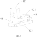
- the movable seat 40 includes a sliding groove 41 and a sliding component 42 which is accommodated in the sliding groove 41 and cooperates with the sliding groove 41, the sliding component 42 is fixedly connected with the first shell 102 and/or the second shell 103.
- the sliding groove 41 includes a sliding rail 411 cooperating with the sliding component 42 and a limiting plate 412 which limits the sliding distance of the sliding component 42.
- the sliding component 42 includes a limiting embossment 421 cooperating with the limiting plate 412, a fixing component 422 parallel to the limiting embossment 421 and a carrying plate 423 accommodated in the sliding rail 411 which carries the limiting embossment 421 and the fixing component 422, the fixing component 422 is fixed with the first shell 102 and/or the second shell 103 through bolt and nut.
- the limiting embossment 421 and the fixing component 422 are both provided with a supporting component 43 for cooperating with the sliding rail 411.
- the distance between the limiting embossment 421 and the fixing component 422 is much larger than the thickness of the connecting tab 101.
- the material of the movable seat 40 is nylon, so that both the sliding component 42 and the sliding groove 41 are relatively wear-resisting, which improves the service life of the power battery pack apparatus of the present invention.
- An insulating plate (not labeled) and a thermal conductive adhesive (not labeled) used for conducting heat of the battery are provided between the cell 10 and the base 40, the thermal conductive adhesive is provided under the insulating plate, the thermal conductive adhesive is configured to conduct the heat of the cell 10, so as to facilitate heat dissipation.
- the operating principle of the present invention is: the cell 10 is accommodated in the first shell 102 and the second shell 103, the first shell 102 and the second shell 103 are alternatively arranged, and are fixedly connected as a cell module by the connecting tab 101, the bolt 200, the bolt hole and the nut 201, the cell module is placed in the groove of the base 40, the outmost first shell 102 and second shell 103 are fixedly connected with the movable seat 40 through a connecting tab 101 respectively.
- the carrying plate 423 slides in from an end of the sliding groove 41, and is limited by the sliding rail 411 in vertical direction, adjusting the sliding component 42, so that the fixing component 422 is aligned with the connecting tab 101, and then fixing by using bolt and nut.
- the sliding component 42 slides to any of the two sides along the sliding rail 411, so that the cell 10 will not be blocked when expanding, moreover, the side plate 301 of the base 40 and the limiting embossment 421 of the movable seat 40 further limit the cell module, so as to prevent the cell module from sliding out of the groove.
- the supporting component 43 of the limiting embossment 421 and fixing component 422 on the movable seat 40 abut and press on the sliding rail 411, two supporting components 43 are provided at the front and back respectively, so as to balance the force subjected by the cell module.
- the movable seat 40 is adopted to prevent the cell module from being blocked by outer force when expanding, so that the cell 10 of the present invention can be fixed into a module quickly, and will not affect the battery expanding, that is, in the battery expanding process, it will not receive outer resistance, so as to improve safety of the battery and show better heat dissipation effect.
Landscapes
- Chemical & Material Sciences (AREA)
- Chemical Kinetics & Catalysis (AREA)
- Electrochemistry (AREA)
- General Chemical & Material Sciences (AREA)
- Engineering & Computer Science (AREA)
- Manufacturing & Machinery (AREA)
- Battery Mounting, Suspending (AREA)
Claims (8)
- Appareil bloc-batterie d'alimentation, caractérisé en ce que l'appareil bloc-batterie d'alimentation comprend une pluralité de cellules (10) et de composants de connexion (20),
la pluralité de cellules (10) sont successivement empilées le long d'une direction d'épaisseur de la cellule pour former un module de cellules, chacune des cellules (10) comprenant un corps principal de cellule (100) et au moins deux pattes de connexion (101),
toutes les pattes de connexion (101) font saillie depuis une partie latérale du corps principal de cellule et sont fixées au corps principal de cellule (100), et deux des pattes de connexion (101) correspondant à deux cellules adjacentes quelconques (10) sont connectées par un composant de connexion (20), de sorte que les deux cellules adjacentes quelconques (10) sont connectées l'une à l'autre,
l'appareil bloc-batterie d'alimentation comprend en outre une base (30) portant le module de cellules et une pluralité de sièges mobiles (40),
la pluralité de sièges mobiles (40) sont agencés respectivement sur deux côtés symétriques de la base (30), les cellules (10) situées aux deux extrémités du module de cellules sont agencées de manière fixe avec les sièges mobiles (40) de côtés correspondants, et les sièges mobiles (40) peuvent coulisser dans la direction d'épaisseur de la cellule. - Appareil bloc-batterie d'alimentation selon la revendication 1, caractérisé en ce que les pattes de connexion (101) d'une cellule pour connecter respectivement des cellules adjacentes (10) des deux côtés de la cellule (10) sont espacées dans une direction de hauteur de la cellule, dans lequel la direction de hauteur est une direction perpendiculaire à la base (30).
- Appareil bloc-batterie d'alimentation selon la revendication 1, caractérisé en ce qu'un trou de boulon est prévu sur la patte de connexion (101), le composant de connexion (20) comprend un boulon (200) et un écrou (201), chaque groupe des pattes de connexion (101) sont connectées par le boulon (200) s'étendant à travers le trou de boulon et l'écrou (201).
- Appareil bloc-batterie d'alimentation selon la revendication 1, caractérisé en ce que le siège mobile (40) comprend une rainure de coulissement (41) et un composant coulissant (42) qui est reçu dans la rainure de coulissement (41) et coopère avec la rainure de coulissement (41), la rainure de coulissement (41) est prévue sur la base (30) dans la direction d'épaisseur de la cellule, le composant coulissant (42) est relié à la cellule.
- Appareil bloc-batterie d'alimentation selon la revendication 4, caractérisé en ce que les pattes de connexion (101) correspondant au composant coulissant (42) sont agencées sur les cellules (10) situées aux deux extrémités du module de cellules, les pattes de connexion (101) sont connectées au composant coulissant (42) par le biais du composant de connexion (20), de sorte que la cellule est connectée au composant coulissant (42).
- Appareil bloc-batterie d'alimentation selon la revendication 5, caractérisé en ce que la rainure de coulissement (41) comprend un rail de coulissement (411) coopérant avec l'élément coulissant (42) et une plaque de limitation (412) qui limite une distance de coulissement du composant coulissant (42), le composant coulissant (42) comprend un relief de limitation (421) coopérant avec la plaque de limitation (412), un composant de fixation (422) parallèle au relief de limitation (421) et une plaque de support reçue dans le rail de coulissement (411) qui supporte le relief de limitation (421) et le composant de fixation (422), le composant de fixation (422) est fixé à la cellule.
- Appareil bloc-batterie d'alimentation selon la revendication 6, caractérisé en ce que le relief de limitation (421) et l'élément de fixation (422) sont pourvus d'un composant de support (43) coopérant avec le rail de coulissement (411).
- Appareil bloc-batterie d'alimentation selon la revendication 7, caractérisé en ce qu'une distance entre le relief de limitation (421) et le composant de fixation (422) est supérieure à une épaisseur de la patte de connexion (101).
Applications Claiming Priority (1)
| Application Number | Priority Date | Filing Date | Title |
|---|---|---|---|
| CN201610109698.XA CN105591060B (zh) | 2016-02-25 | 2016-02-25 | 动力电池组装置 |
Publications (2)
| Publication Number | Publication Date |
|---|---|
| EP3211686A1 EP3211686A1 (fr) | 2017-08-30 |
| EP3211686B1 true EP3211686B1 (fr) | 2019-03-13 |
Family
ID=55930469
Family Applications (1)
| Application Number | Title | Priority Date | Filing Date |
|---|---|---|---|
| EP16202751.0A Active EP3211686B1 (fr) | 2016-02-25 | 2016-12-07 | Appareil de bloc batterie d'alimentation |
Country Status (3)
| Country | Link |
|---|---|
| US (1) | US20170250386A1 (fr) |
| EP (1) | EP3211686B1 (fr) |
| CN (1) | CN105591060B (fr) |
Families Citing this family (12)
| Publication number | Priority date | Publication date | Assignee | Title |
|---|---|---|---|---|
| CN207818678U (zh) | 2017-12-28 | 2018-09-04 | 宁德时代新能源科技股份有限公司 | 壳体、电池模组及电池包 |
| CN109103385B (zh) * | 2018-09-25 | 2024-09-20 | 华霆(合肥)动力技术有限公司 | 软包电池箱体及电池模组 |
| WO2020077333A1 (fr) | 2018-10-12 | 2020-04-16 | Ppg Industries Ohio, Inc. | Compositions contenant des charges thermoconductrices |
| CN109687190B (zh) * | 2018-11-22 | 2022-05-27 | 福建省汽车工业集团云度新能源汽车股份有限公司 | 一种电池包内部对插模组及模组单元 |
| CN110379969B (zh) * | 2019-07-26 | 2022-03-22 | 贵州大学 | 一种新能源电动汽车电池的组装外壳 |
| CN111883712B (zh) * | 2020-08-14 | 2024-10-25 | 傲普(上海)新能源有限公司 | 储能电池柜 |
| CN113206338B (zh) * | 2021-03-24 | 2024-08-16 | 合众新能源汽车股份有限公司 | 一种延迟电动汽车动力电池热失控时间的结构 |
| JP7349029B2 (ja) * | 2021-05-20 | 2023-09-21 | 寧徳時代新能源科技股▲分▼有限公司 | リチウムイオン二次電池、電池モジュール、電池パックおよび電気装置 |
| CN113839138B (zh) * | 2021-09-22 | 2024-02-23 | 蜂巢能源科技有限公司 | 安装支架、电池模组及电池包 |
| CN115117533A (zh) * | 2022-06-02 | 2022-09-27 | 远景动力技术(江苏)有限公司 | 一种电池模组及电子装置 |
| CN116691564A (zh) * | 2023-06-13 | 2023-09-05 | 北京嘉诚兴业工贸股份有限公司 | 一种乘用车蓄电池托盘结构 |
| CN116960560B (zh) * | 2023-09-19 | 2024-01-05 | 中宏科创新能源科技(浙江)有限公司 | 电池夹紧装置及其安装方法、拆卸方法和调节方法 |
Family Cites Families (12)
| Publication number | Priority date | Publication date | Assignee | Title |
|---|---|---|---|---|
| KR100903185B1 (ko) * | 2005-05-02 | 2009-06-17 | 주식회사 엘지화학 | 향상된 안전성의 개선된 중대형 전지팩 |
| JP4775436B2 (ja) * | 2008-02-29 | 2011-09-21 | 日産自動車株式会社 | 電池モジュールおよび電池モジュールの製造方法 |
| DE102009010794A1 (de) * | 2009-02-27 | 2010-09-02 | Li-Tec Battery Gmbh | Galvanische Zelle mit Rahmen und Verfahren zu ihrer Herstellung |
| US9252894B2 (en) * | 2011-05-17 | 2016-02-02 | Telefonaktiebolaget L M Ericsson (Publ) | Method and arrangement for supporting calibration of correlated antennas |
| JP5968211B2 (ja) * | 2012-02-14 | 2016-08-10 | 住友重機械工業株式会社 | 蓄電モジュール、その製造方法、及び作業機械 |
| WO2013145917A1 (fr) * | 2012-03-27 | 2013-10-03 | ソニー株式会社 | Unité galvanique, module galvanique, système de stockage d'énergie, équipement électronique, système à énergie électrique et véhicule électrique |
| JP2014175078A (ja) * | 2013-03-06 | 2014-09-22 | Captex Co Ltd | 電池パック |
| KR101699867B1 (ko) * | 2013-07-25 | 2017-01-25 | 주식회사 엘지화학 | 이동형 가압부재를 포함하는 전지모듈 |
| JP6281398B2 (ja) * | 2014-04-21 | 2018-02-21 | 株式会社豊田自動織機 | 電池モジュール |
| EP3161899A4 (fr) * | 2014-06-30 | 2017-12-27 | Black & Decker Inc. | Bloc-batterie pour des outils électriques sans fil |
| CN204315650U (zh) * | 2015-01-05 | 2015-05-06 | 天津市捷威动力工业有限公司 | 一种折叠式电芯组装架 |
| CN205355134U (zh) * | 2016-02-25 | 2016-06-29 | 宁德时代新能源科技股份有限公司 | 动力电池组装置 |
-
2016
- 2016-02-25 CN CN201610109698.XA patent/CN105591060B/zh active Active
- 2016-12-07 EP EP16202751.0A patent/EP3211686B1/fr active Active
-
2017
- 2017-02-17 US US15/436,687 patent/US20170250386A1/en not_active Abandoned
Non-Patent Citations (1)
| Title |
|---|
| None * |
Also Published As
| Publication number | Publication date |
|---|---|
| CN105591060A (zh) | 2016-05-18 |
| EP3211686A1 (fr) | 2017-08-30 |
| CN105591060B (zh) | 2019-09-03 |
| US20170250386A1 (en) | 2017-08-31 |
Similar Documents
| Publication | Publication Date | Title |
|---|---|---|
| EP3211686B1 (fr) | Appareil de bloc batterie d'alimentation | |
| US9716297B2 (en) | Energy storage module and system | |
| US11482716B2 (en) | Assembly system that assembles insulating plate and mounting bar, and assembly method | |
| US20170237113A1 (en) | Receptacle for a battery module, and battery module having a receptacle of this kind | |
| US20140038021A1 (en) | Energy Storage Module Comprising a Plurality of Prismatic Storage Cells | |
| KR102697495B1 (ko) | 연료 전지 스택 압축의 시스템 및 방법 | |
| CN206717300U (zh) | 电芯焊接工装 | |
| JP6606896B2 (ja) | 電池モジュール | |
| WO2020135154A1 (fr) | Bloc-batterie et cadre pour bloc-batterie | |
| JP2018534742A (ja) | バッテリー用冷却モジュール、乗り物用バッテリー、及び冷却モジュールを製造するための方法 | |
| WO2021093084A1 (fr) | Pince de regroupement de modules de batterie et procédé d'utilisation | |
| US10461382B2 (en) | Receptacle for a battery module and battery module having such a receptacle | |
| JP2020077577A (ja) | 燃料電池スタック及びその組立方法 | |
| CN102944470A (zh) | 弯曲实验夹具组件、弯曲实验夹具和压缩实验夹具 | |
| JP5445041B2 (ja) | 電力変換装置 | |
| US20150180097A1 (en) | Energy Storage Module and Method for Production of Energy Storage Module | |
| US11942590B2 (en) | Battery module including nodal cell compression and heat rejection | |
| JP5288402B2 (ja) | 治具 | |
| CN205355134U (zh) | 动力电池组装置 | |
| JP2009199910A (ja) | 燃料電池スタックの締結構造 | |
| CN105082234A (zh) | 一种通用夹钳 | |
| GB2508925A (en) | Annular busbar clamp with cam-urged springs | |
| CN210360035U (zh) | 焊接工装 | |
| JP2004335777A (ja) | 平型半導体素子用スタック | |
| KR20190032500A (ko) | 에너지 저장 유닛을 냉각시키기 위한 장치, 및 관련 조립체 |
Legal Events
| Date | Code | Title | Description |
|---|---|---|---|
| PUAI | Public reference made under article 153(3) epc to a published international application that has entered the european phase |
Free format text: ORIGINAL CODE: 0009012 |
|
| STAA | Information on the status of an ep patent application or granted ep patent |
Free format text: STATUS: REQUEST FOR EXAMINATION WAS MADE |
|
| 17P | Request for examination filed |
Effective date: 20161207 |
|
| AK | Designated contracting states |
Kind code of ref document: A1 Designated state(s): AL AT BE BG CH CY CZ DE DK EE ES FI FR GB GR HR HU IE IS IT LI LT LU LV MC MK MT NL NO PL PT RO RS SE SI SK SM TR |
|
| AX | Request for extension of the european patent |
Extension state: BA ME |
|
| STAA | Information on the status of an ep patent application or granted ep patent |
Free format text: STATUS: EXAMINATION IS IN PROGRESS |
|
| 17Q | First examination report despatched |
Effective date: 20180611 |
|
| GRAP | Despatch of communication of intention to grant a patent |
Free format text: ORIGINAL CODE: EPIDOSNIGR1 |
|
| STAA | Information on the status of an ep patent application or granted ep patent |
Free format text: STATUS: GRANT OF PATENT IS INTENDED |
|
| INTG | Intention to grant announced |
Effective date: 20181019 |
|
| GRAS | Grant fee paid |
Free format text: ORIGINAL CODE: EPIDOSNIGR3 |
|
| GRAA | (expected) grant |
Free format text: ORIGINAL CODE: 0009210 |
|
| STAA | Information on the status of an ep patent application or granted ep patent |
Free format text: STATUS: THE PATENT HAS BEEN GRANTED |
|
| AK | Designated contracting states |
Kind code of ref document: B1 Designated state(s): AL AT BE BG CH CY CZ DE DK EE ES FI FR GB GR HR HU IE IS IT LI LT LU LV MC MK MT NL NO PL PT RO RS SE SI SK SM TR |
|
| REG | Reference to a national code |
Ref country code: GB Ref legal event code: FG4D |
|
| REG | Reference to a national code |
Ref country code: CH Ref legal event code: EP Ref country code: AT Ref legal event code: REF Ref document number: 1108915 Country of ref document: AT Kind code of ref document: T Effective date: 20190315 |
|
| REG | Reference to a national code |
Ref country code: DE Ref legal event code: R096 Ref document number: 602016010986 Country of ref document: DE |
|
| REG | Reference to a national code |
Ref country code: IE Ref legal event code: FG4D |
|
| REG | Reference to a national code |
Ref country code: NL Ref legal event code: MP Effective date: 20190313 |
|
| REG | Reference to a national code |
Ref country code: LT Ref legal event code: MG4D |
|
| PG25 | Lapsed in a contracting state [announced via postgrant information from national office to epo] |
Ref country code: SE Free format text: LAPSE BECAUSE OF FAILURE TO SUBMIT A TRANSLATION OF THE DESCRIPTION OR TO PAY THE FEE WITHIN THE PRESCRIBED TIME-LIMIT Effective date: 20190313 Ref country code: FI Free format text: LAPSE BECAUSE OF FAILURE TO SUBMIT A TRANSLATION OF THE DESCRIPTION OR TO PAY THE FEE WITHIN THE PRESCRIBED TIME-LIMIT Effective date: 20190313 Ref country code: NO Free format text: LAPSE BECAUSE OF FAILURE TO SUBMIT A TRANSLATION OF THE DESCRIPTION OR TO PAY THE FEE WITHIN THE PRESCRIBED TIME-LIMIT Effective date: 20190613 Ref country code: LT Free format text: LAPSE BECAUSE OF FAILURE TO SUBMIT A TRANSLATION OF THE DESCRIPTION OR TO PAY THE FEE WITHIN THE PRESCRIBED TIME-LIMIT Effective date: 20190313 |
|
| PG25 | Lapsed in a contracting state [announced via postgrant information from national office to epo] |
Ref country code: BG Free format text: LAPSE BECAUSE OF FAILURE TO SUBMIT A TRANSLATION OF THE DESCRIPTION OR TO PAY THE FEE WITHIN THE PRESCRIBED TIME-LIMIT Effective date: 20190613 Ref country code: GR Free format text: LAPSE BECAUSE OF FAILURE TO SUBMIT A TRANSLATION OF THE DESCRIPTION OR TO PAY THE FEE WITHIN THE PRESCRIBED TIME-LIMIT Effective date: 20190614 Ref country code: HR Free format text: LAPSE BECAUSE OF FAILURE TO SUBMIT A TRANSLATION OF THE DESCRIPTION OR TO PAY THE FEE WITHIN THE PRESCRIBED TIME-LIMIT Effective date: 20190313 Ref country code: LV Free format text: LAPSE BECAUSE OF FAILURE TO SUBMIT A TRANSLATION OF THE DESCRIPTION OR TO PAY THE FEE WITHIN THE PRESCRIBED TIME-LIMIT Effective date: 20190313 Ref country code: NL Free format text: LAPSE BECAUSE OF FAILURE TO SUBMIT A TRANSLATION OF THE DESCRIPTION OR TO PAY THE FEE WITHIN THE PRESCRIBED TIME-LIMIT Effective date: 20190313 Ref country code: RS Free format text: LAPSE BECAUSE OF FAILURE TO SUBMIT A TRANSLATION OF THE DESCRIPTION OR TO PAY THE FEE WITHIN THE PRESCRIBED TIME-LIMIT Effective date: 20190313 |
|
| REG | Reference to a national code |
Ref country code: AT Ref legal event code: MK05 Ref document number: 1108915 Country of ref document: AT Kind code of ref document: T Effective date: 20190313 |
|
| PG25 | Lapsed in a contracting state [announced via postgrant information from national office to epo] |
Ref country code: CZ Free format text: LAPSE BECAUSE OF FAILURE TO SUBMIT A TRANSLATION OF THE DESCRIPTION OR TO PAY THE FEE WITHIN THE PRESCRIBED TIME-LIMIT Effective date: 20190313 Ref country code: IT Free format text: LAPSE BECAUSE OF FAILURE TO SUBMIT A TRANSLATION OF THE DESCRIPTION OR TO PAY THE FEE WITHIN THE PRESCRIBED TIME-LIMIT Effective date: 20190313 Ref country code: ES Free format text: LAPSE BECAUSE OF FAILURE TO SUBMIT A TRANSLATION OF THE DESCRIPTION OR TO PAY THE FEE WITHIN THE PRESCRIBED TIME-LIMIT Effective date: 20190313 Ref country code: RO Free format text: LAPSE BECAUSE OF FAILURE TO SUBMIT A TRANSLATION OF THE DESCRIPTION OR TO PAY THE FEE WITHIN THE PRESCRIBED TIME-LIMIT Effective date: 20190313 Ref country code: EE Free format text: LAPSE BECAUSE OF FAILURE TO SUBMIT A TRANSLATION OF THE DESCRIPTION OR TO PAY THE FEE WITHIN THE PRESCRIBED TIME-LIMIT Effective date: 20190313 Ref country code: PT Free format text: LAPSE BECAUSE OF FAILURE TO SUBMIT A TRANSLATION OF THE DESCRIPTION OR TO PAY THE FEE WITHIN THE PRESCRIBED TIME-LIMIT Effective date: 20190713 Ref country code: SK Free format text: LAPSE BECAUSE OF FAILURE TO SUBMIT A TRANSLATION OF THE DESCRIPTION OR TO PAY THE FEE WITHIN THE PRESCRIBED TIME-LIMIT Effective date: 20190313 Ref country code: AL Free format text: LAPSE BECAUSE OF FAILURE TO SUBMIT A TRANSLATION OF THE DESCRIPTION OR TO PAY THE FEE WITHIN THE PRESCRIBED TIME-LIMIT Effective date: 20190313 |
|
| PG25 | Lapsed in a contracting state [announced via postgrant information from national office to epo] |
Ref country code: PL Free format text: LAPSE BECAUSE OF FAILURE TO SUBMIT A TRANSLATION OF THE DESCRIPTION OR TO PAY THE FEE WITHIN THE PRESCRIBED TIME-LIMIT Effective date: 20190313 Ref country code: SM Free format text: LAPSE BECAUSE OF FAILURE TO SUBMIT A TRANSLATION OF THE DESCRIPTION OR TO PAY THE FEE WITHIN THE PRESCRIBED TIME-LIMIT Effective date: 20190313 |
|
| REG | Reference to a national code |
Ref country code: DE Ref legal event code: R097 Ref document number: 602016010986 Country of ref document: DE |
|
| PG25 | Lapsed in a contracting state [announced via postgrant information from national office to epo] |
Ref country code: AT Free format text: LAPSE BECAUSE OF FAILURE TO SUBMIT A TRANSLATION OF THE DESCRIPTION OR TO PAY THE FEE WITHIN THE PRESCRIBED TIME-LIMIT Effective date: 20190313 Ref country code: IS Free format text: LAPSE BECAUSE OF FAILURE TO SUBMIT A TRANSLATION OF THE DESCRIPTION OR TO PAY THE FEE WITHIN THE PRESCRIBED TIME-LIMIT Effective date: 20190713 |
|
| PLBE | No opposition filed within time limit |
Free format text: ORIGINAL CODE: 0009261 |
|
| STAA | Information on the status of an ep patent application or granted ep patent |
Free format text: STATUS: NO OPPOSITION FILED WITHIN TIME LIMIT |
|
| PG25 | Lapsed in a contracting state [announced via postgrant information from national office to epo] |
Ref country code: DK Free format text: LAPSE BECAUSE OF FAILURE TO SUBMIT A TRANSLATION OF THE DESCRIPTION OR TO PAY THE FEE WITHIN THE PRESCRIBED TIME-LIMIT Effective date: 20190313 |
|
| 26N | No opposition filed |
Effective date: 20191216 |
|
| PG25 | Lapsed in a contracting state [announced via postgrant information from national office to epo] |
Ref country code: SI Free format text: LAPSE BECAUSE OF FAILURE TO SUBMIT A TRANSLATION OF THE DESCRIPTION OR TO PAY THE FEE WITHIN THE PRESCRIBED TIME-LIMIT Effective date: 20190313 |
|
| PG25 | Lapsed in a contracting state [announced via postgrant information from national office to epo] |
Ref country code: TR Free format text: LAPSE BECAUSE OF FAILURE TO SUBMIT A TRANSLATION OF THE DESCRIPTION OR TO PAY THE FEE WITHIN THE PRESCRIBED TIME-LIMIT Effective date: 20190313 |
|
| REG | Reference to a national code |
Ref country code: CH Ref legal event code: PL |
|
| REG | Reference to a national code |
Ref country code: BE Ref legal event code: MM Effective date: 20191231 |
|
| PG25 | Lapsed in a contracting state [announced via postgrant information from national office to epo] |
Ref country code: MC Free format text: LAPSE BECAUSE OF FAILURE TO SUBMIT A TRANSLATION OF THE DESCRIPTION OR TO PAY THE FEE WITHIN THE PRESCRIBED TIME-LIMIT Effective date: 20190313 |
|
| PG25 | Lapsed in a contracting state [announced via postgrant information from national office to epo] |
Ref country code: IE Free format text: LAPSE BECAUSE OF NON-PAYMENT OF DUE FEES Effective date: 20191207 Ref country code: LU Free format text: LAPSE BECAUSE OF NON-PAYMENT OF DUE FEES Effective date: 20191207 |
|
| REG | Reference to a national code |
Ref country code: DE Ref legal event code: R079 Ref document number: 602016010986 Country of ref document: DE Free format text: PREVIOUS MAIN CLASS: H01M0002020000 Ipc: H01M0050100000 |
|
| PG25 | Lapsed in a contracting state [announced via postgrant information from national office to epo] |
Ref country code: CH Free format text: LAPSE BECAUSE OF NON-PAYMENT OF DUE FEES Effective date: 20191231 Ref country code: BE Free format text: LAPSE BECAUSE OF NON-PAYMENT OF DUE FEES Effective date: 20191231 Ref country code: LI Free format text: LAPSE BECAUSE OF NON-PAYMENT OF DUE FEES Effective date: 20191231 |
|
| PG25 | Lapsed in a contracting state [announced via postgrant information from national office to epo] |
Ref country code: CY Free format text: LAPSE BECAUSE OF FAILURE TO SUBMIT A TRANSLATION OF THE DESCRIPTION OR TO PAY THE FEE WITHIN THE PRESCRIBED TIME-LIMIT Effective date: 20190313 |
|
| PG25 | Lapsed in a contracting state [announced via postgrant information from national office to epo] |
Ref country code: HU Free format text: LAPSE BECAUSE OF FAILURE TO SUBMIT A TRANSLATION OF THE DESCRIPTION OR TO PAY THE FEE WITHIN THE PRESCRIBED TIME-LIMIT; INVALID AB INITIO Effective date: 20161207 Ref country code: MT Free format text: LAPSE BECAUSE OF FAILURE TO SUBMIT A TRANSLATION OF THE DESCRIPTION OR TO PAY THE FEE WITHIN THE PRESCRIBED TIME-LIMIT Effective date: 20190313 |
|
| PG25 | Lapsed in a contracting state [announced via postgrant information from national office to epo] |
Ref country code: MK Free format text: LAPSE BECAUSE OF FAILURE TO SUBMIT A TRANSLATION OF THE DESCRIPTION OR TO PAY THE FEE WITHIN THE PRESCRIBED TIME-LIMIT Effective date: 20190313 |
|
| P01 | Opt-out of the competence of the unified patent court (upc) registered |
Effective date: 20230516 |
|
| REG | Reference to a national code |
Ref country code: DE Ref legal event code: R082 Ref document number: 602016010986 Country of ref document: DE Ref country code: DE Ref legal event code: R081 Ref document number: 602016010986 Country of ref document: DE Owner name: CONTEMPORARY AMPEREX TECHNOLOGY (HONG KONG) LI, HK Free format text: FORMER OWNER: CONTEMPORARY AMPEREX TECHNOLOGY CO., LTD., NINGDE CITY, FUJIAN, CN |
|
| REG | Reference to a national code |
Ref country code: GB Ref legal event code: 732E Free format text: REGISTERED BETWEEN 20240815 AND 20240821 |
|
| PGFP | Annual fee paid to national office [announced via postgrant information from national office to epo] |
Ref country code: FR Payment date: 20250930 Year of fee payment: 10 |
|
| PGFP | Annual fee paid to national office [announced via postgrant information from national office to epo] |
Ref country code: DE Payment date: 20250930 Year of fee payment: 10 |
|
| PGFP | Annual fee paid to national office [announced via postgrant information from national office to epo] |
Ref country code: GB Payment date: 20251001 Year of fee payment: 10 |