EP3211806B1 - Kanalstatusinformationsrückkopplung und erfassungsverfahren und -vorrichtung - Google Patents
Kanalstatusinformationsrückkopplung und erfassungsverfahren und -vorrichtung Download PDFInfo
- Publication number
- EP3211806B1 EP3211806B1 EP15853245.7A EP15853245A EP3211806B1 EP 3211806 B1 EP3211806 B1 EP 3211806B1 EP 15853245 A EP15853245 A EP 15853245A EP 3211806 B1 EP3211806 B1 EP 3211806B1
- Authority
- EP
- European Patent Office
- Prior art keywords
- dimension
- csi
- information
- pilot
- resource
- Prior art date
- Legal status (The legal status is an assumption and is not a legal conclusion. Google has not performed a legal analysis and makes no representation as to the accuracy of the status listed.)
- Active
Links
Images




Classifications
-
- H—ELECTRICITY
- H04—ELECTRIC COMMUNICATION TECHNIQUE
- H04B—TRANSMISSION
- H04B7/00—Radio transmission systems, i.e. using radiation field
- H04B7/02—Diversity systems; Multi-antenna system, i.e. transmission or reception using multiple antennas
- H04B7/04—Diversity systems; Multi-antenna system, i.e. transmission or reception using multiple antennas using two or more spaced independent antennas
- H04B7/06—Diversity systems; Multi-antenna system, i.e. transmission or reception using multiple antennas using two or more spaced independent antennas at the transmitting station
- H04B7/0613—Diversity systems; Multi-antenna system, i.e. transmission or reception using multiple antennas using two or more spaced independent antennas at the transmitting station using simultaneous transmission
- H04B7/0615—Diversity systems; Multi-antenna system, i.e. transmission or reception using multiple antennas using two or more spaced independent antennas at the transmitting station using simultaneous transmission of weighted versions of same signal
- H04B7/0617—Diversity systems; Multi-antenna system, i.e. transmission or reception using multiple antennas using two or more spaced independent antennas at the transmitting station using simultaneous transmission of weighted versions of same signal for beam forming
-
- H—ELECTRICITY
- H04—ELECTRIC COMMUNICATION TECHNIQUE
- H04B—TRANSMISSION
- H04B7/00—Radio transmission systems, i.e. using radiation field
- H04B7/02—Diversity systems; Multi-antenna system, i.e. transmission or reception using multiple antennas
- H04B7/04—Diversity systems; Multi-antenna system, i.e. transmission or reception using multiple antennas using two or more spaced independent antennas
- H04B7/06—Diversity systems; Multi-antenna system, i.e. transmission or reception using multiple antennas using two or more spaced independent antennas at the transmitting station
- H04B7/0613—Diversity systems; Multi-antenna system, i.e. transmission or reception using multiple antennas using two or more spaced independent antennas at the transmitting station using simultaneous transmission
- H04B7/0615—Diversity systems; Multi-antenna system, i.e. transmission or reception using multiple antennas using two or more spaced independent antennas at the transmitting station using simultaneous transmission of weighted versions of same signal
- H04B7/0619—Diversity systems; Multi-antenna system, i.e. transmission or reception using multiple antennas using two or more spaced independent antennas at the transmitting station using simultaneous transmission of weighted versions of same signal using feedback from receiving side
- H04B7/0621—Feedback content
- H04B7/0626—Channel coefficients, e.g. channel state information [CSI]
-
- H—ELECTRICITY
- H04—ELECTRIC COMMUNICATION TECHNIQUE
- H04B—TRANSMISSION
- H04B7/00—Radio transmission systems, i.e. using radiation field
- H04B7/02—Diversity systems; Multi-antenna system, i.e. transmission or reception using multiple antennas
- H04B7/04—Diversity systems; Multi-antenna system, i.e. transmission or reception using multiple antennas using two or more spaced independent antennas
- H04B7/0413—MIMO systems
- H04B7/0456—Selection of precoding matrices or codebooks, e.g. using matrices antenna weighting
- H04B7/0478—Special codebook structures directed to feedback optimisation
- H04B7/0479—Special codebook structures directed to feedback optimisation for multi-dimensional arrays, e.g. horizontal or vertical pre-distortion matrix index [PMI]
-
- H—ELECTRICITY
- H04—ELECTRIC COMMUNICATION TECHNIQUE
- H04B—TRANSMISSION
- H04B7/00—Radio transmission systems, i.e. using radiation field
- H04B7/02—Diversity systems; Multi-antenna system, i.e. transmission or reception using multiple antennas
- H04B7/04—Diversity systems; Multi-antenna system, i.e. transmission or reception using multiple antennas using two or more spaced independent antennas
- H04B7/06—Diversity systems; Multi-antenna system, i.e. transmission or reception using multiple antennas using two or more spaced independent antennas at the transmitting station
- H04B7/0613—Diversity systems; Multi-antenna system, i.e. transmission or reception using multiple antennas using two or more spaced independent antennas at the transmitting station using simultaneous transmission
- H04B7/0615—Diversity systems; Multi-antenna system, i.e. transmission or reception using multiple antennas using two or more spaced independent antennas at the transmitting station using simultaneous transmission of weighted versions of same signal
- H04B7/0619—Diversity systems; Multi-antenna system, i.e. transmission or reception using multiple antennas using two or more spaced independent antennas at the transmitting station using simultaneous transmission of weighted versions of same signal using feedback from receiving side
- H04B7/0621—Feedback content
- H04B7/063—Parameters other than those covered in groups H04B7/0623 - H04B7/0634, e.g. channel matrix rank or transmit mode selection
-
- H—ELECTRICITY
- H04—ELECTRIC COMMUNICATION TECHNIQUE
- H04B—TRANSMISSION
- H04B7/00—Radio transmission systems, i.e. using radiation field
- H04B7/02—Diversity systems; Multi-antenna system, i.e. transmission or reception using multiple antennas
- H04B7/04—Diversity systems; Multi-antenna system, i.e. transmission or reception using multiple antennas using two or more spaced independent antennas
- H04B7/06—Diversity systems; Multi-antenna system, i.e. transmission or reception using multiple antennas using two or more spaced independent antennas at the transmitting station
- H04B7/0613—Diversity systems; Multi-antenna system, i.e. transmission or reception using multiple antennas using two or more spaced independent antennas at the transmitting station using simultaneous transmission
- H04B7/0615—Diversity systems; Multi-antenna system, i.e. transmission or reception using multiple antennas using two or more spaced independent antennas at the transmitting station using simultaneous transmission of weighted versions of same signal
- H04B7/0619—Diversity systems; Multi-antenna system, i.e. transmission or reception using multiple antennas using two or more spaced independent antennas at the transmitting station using simultaneous transmission of weighted versions of same signal using feedback from receiving side
- H04B7/0636—Feedback format
- H04B7/0639—Using selective indices, e.g. of a codebook, e.g. pre-distortion matrix index [PMI] or for beam selection
-
- H—ELECTRICITY
- H04—ELECTRIC COMMUNICATION TECHNIQUE
- H04L—TRANSMISSION OF DIGITAL INFORMATION, e.g. TELEGRAPHIC COMMUNICATION
- H04L5/00—Arrangements affording multiple use of the transmission path
- H04L5/003—Arrangements for allocating sub-channels of the transmission path
- H04L5/0048—Allocation of pilot signals, i.e. of signals known to the receiver
-
- H—ELECTRICITY
- H04—ELECTRIC COMMUNICATION TECHNIQUE
- H04L—TRANSMISSION OF DIGITAL INFORMATION, e.g. TELEGRAPHIC COMMUNICATION
- H04L5/00—Arrangements affording multiple use of the transmission path
- H04L5/003—Arrangements for allocating sub-channels of the transmission path
- H04L5/0053—Allocation of signalling, i.e. of overhead other than pilot signals
- H04L5/0057—Physical resource allocation for CQI
-
- H—ELECTRICITY
- H04—ELECTRIC COMMUNICATION TECHNIQUE
- H04W—WIRELESS COMMUNICATION NETWORKS
- H04W88/00—Devices specially adapted for wireless communication networks, e.g. terminals, base stations or access point devices
- H04W88/02—Terminal devices
Definitions
- the present disclosure relates to the field of communication technology, in particular to a channel state information (CSI) feedback method, a CSI acquisition method, a CSI feedback device and a CSI acquisition device.
- CSI channel state information
- antennae of a base station are usually arranged horizontally in an array form. Beams from a transmitter of the base station may merely be adjusted in a horizontal direction, and the each beam is provided with a fixed down-tilt angle in a vertical direction.
- various beamforming/precoding technologies may be performed on the basis of channel information in the horizontal direction.
- a radio signal is transmitted in a space in a three-dimensional (3D) manner, so it is impossible to provide an optimal system performance through the fixed down-tilt angle.
- MIMO Multiple Input Multiple Output
- the antennae arranged horizontally in a 2D manner may be replaced with the antennae arranged horizontally and vertically in a 3D manner.
- the 3D beamforming/precoding operation needs to be performed on the basis of CSI reported by a User Equipment (UE).
- UE User Equipment
- the CSI may be reported on the basis of a codebook, as that adopted by a Long Term Evolution (LTE) Release 8 system.
- LTE Long Term Evolution
- CSI-RS Channel State Information Reference Signal
- eNB evolved Node B
- pilot resources may be provided with different vertical beam-forming matrices at an eNB end.
- the UE may measure each pilot resource in the horizontal dimension and report the CSI.
- the CSI feedback mode of a beamforming vector in the vertical dimension is combined with the CSI feedback mode in the horizontal dimension.
- the UE In order to enable eNB to acquire beam information in the vertical dimension, the UE needs to feed back signals measured on the one or more pilot resources, which results in a relatively large uplink feedback overhead.
- the UE needs to be provided with a strong ability of processing the plurality of pilot resources in the vertical dimension (i.e., a plurality of CSI progresses), so the power consumption may increase and the UE design may be very complex, which is thus adverse to the spread of the 3D MIMO technique.
- the method includes: receiving from a base station a first channel status information-reference signal based on CSI-RS configuration information for a first domain antenna group of a two-dimensional antenna structure, which is provided from the base station; reporting to the base station first CSI for the first domain antenna group, which is generated by using the first CSI-RS; receiving from the base station a second CSI-RS based on CSI-RS configuration information for a second domain antenna group of the two-dimensional antenna structure, which is provided from the base station; and reporting to the base station second CSI for the second domain antenna group, which is generated by using the second CSI-RS, wherein the CSI-RS configuration information for the second domain antenna group may be determined based on the first CSI.
- a UE receives first reference signals (RS) from a base station that has a multi-dimensional array of transmit antennas.
- the RSs are transmitted from the BS using a plurality of elevation beams and the UE can select a preferred elevation beam and provide an indication of the preferred elevation beam to the base station.
- the UE subsequently receives RSs from the BS that uses the preferred elevation beam and a plurality of azimuthal ports.
- the UE then provides channel feedback to the BS based on the RSs that were sent using the preferred elevation beam.
- Reference document " WO2014107012A1" discussed a wireless communication system.
- the multi-node system is used with or replaces the conventional centralized antenna system to become a new foundation of cellular communication in order to reduce base station cost and backhaul network maintenance cost while extending service coverage and improving channel capacity and SINR in next-generation mobile communication systems.
- Reference document US2013329664A1 discussed a method and an apparatus for transmitting/receiving channel state information in a multi-antenna system.
- An object of the present disclosure is to provide a CSI acquisition method and a CSI acquisition device, so as to reduce pilot resource overhead configured for the UE and reduce the difficulty in processing the CSI feedback progresses at the UE side, thereby to facilitate the CSI feedback and acquisition and save the resources.
- the present disclosure provides a CSI acquisition method implemented a network side device, including steps of: determining beamforming array information in a first dimension; beamforming a pilot signal in a second dimension in accordance with the beamforming array information in the first dimension, and transmitting the beamformed pilot signal in the second dimension to a UE through a pilot resource in the second dimension; and receiving, from the UE, CSI in the second dimension obtained by the UE by measuring the beamformed pilot signal in the second dimension.
- the pilot signal in the second dimension which needs to be transmitted through the pilot resource in the second dimension pre-configured for the UE, may be beamformed in accordance with the beamforming array information in the first dimension, and then the beamformed pilot signal in the second dimension may be transmitted to the UE through the pilot resource in the second dimension, so that the UE may measure the pilot signal in the second dimension beamformed in accordance with the beamforming array information in the first dimension and the obtained CSI is just overall CSI for a final 3D MIMO antenna array.
- the network side device may directly schedule a link in accordance with the CSI in one dimension reported by the UE, rather than the CSI in two dimensions, so it is able to facilitate the CSI feedback and acquisition, and save the resources.
- the step of determining the beamforming array information in the first dimension includes: pre-configuring a pilot resource in the first dimension for the UE and notifying the UE of the pilot resource in the first dimension; transmitting a pilot signal in the first dimension to the UE through the pilot resource in the first dimension; and receiving, from the UE, CSI in the first dimension obtained by the UE by measuring the pilot signal in the first dimension through the pilot resource in the first dimension, and taking the CSI in the first dimension as the beamforming array information in the first dimension.
- the CSI in the first dimension includes Precoding Matrix Indicator (PMI) information.
- PMI Precoding Matrix Indicator
- the CSI in the first dimension further includes Rank Indicator (RI) information corresponding to the PMI information.
- RI Rank Indicator
- the CSI in the first dimension further includes Channel Quality Indicator (CQI) information obtained by the UE in accordance with the PMI information.
- CQI Channel Quality Indicator
- the step of beamforming the pilot signal in the second dimension in accordance with the beamforming array information in the first dimension includes: beamforming the pilot signal in the second dimension through the CSI in the first dimension which is measured by the UE through the pilot resource in the first dimension and transmitted from the UE; or processing the CSI in the first dimension and beamforming the pilot signal in the second dimension in accordance with the processed CSI in the first dimension.
- the step of determining the beamforming array information in the first dimension includes measuring an uplink channel and measuring the beamforming array information in the first dimension.
- the first dimension is perpendicular to the second dimension.
- the first dimension is a vertical dimension
- the second dimension is a horizontal dimension
- the pilot resource is a CSI-RS resource or a Common Reference Signal (CRS) resource.
- CRS Common Reference Signal
- the present disclosure provides a CSI feedback method implemented by a UE, including steps of: determining a pilot resource in a second dimension pre-configured by a network side device for the UE; measuring a beamformed pilot signal in the second dimension transmitted by the network side device through the pilot resource in the second dimension, to acquire CSI in the second dimension, where the beamformed pilot signal in the second dimension is acquired by beamforming, by the network side device, a pilot signal in the second dimension to be transmitted through the pilot resource in the second dimension in accordance with beamforming array information in a first dimension; and transmitting the CSI in the second dimension to the network side device.
- the network side device may beamform the pilot signal in the second dimension, which needs to be transmitted through the pilot resource in the second dimension pre-configured for the UE, in accordance with the beamforming array information in the first dimension, and then transmit the beamformed pilot signal in the second dimension to the UE through the pilot resource in the second dimension, so that the UE may measure the pilot signal in the second dimension beamformed in accordance with the beamforming array information in the first dimension and the obtained CSI is just overall CSI for a final 3D MIMO antenna array.
- it is unnecessary for the UE to perform measurement and reporting operations with respect to excessive pilot resources thereby it is able to reduce the difficulty in processing the CSI progresses at a UE side, facilitate the CSI feedback and acquisition, and save the resources.
- the CSI feedback method further includes: determining, by the UE, a pilot resource in the first dimension pre-configured by the network side device for the UE: measuring a pilot signal in the first dimension transmitted through the pilot resource in the first dimension, to acquire CSI in the first dimension; and transmitting, by the UE, the CSI in the first dimension to the network side device.
- the CSI in the first dimension includes PMI information.
- the CSI in the first dimension further includes RI information corresponding to the PMI information.
- the CSI in the first dimension further includes CQI information obtained by the UE in accordance with the PMI information.
- the present disclosure provides a CSI acquisition device, including: a first unit configured to determine beamforming array information in a first dimension; a second unit configured to beamform a pilot signal in a second dimension in accordance with the beamforming array information in the first dimension, and transmit the beamformed pilot signal in the second dimension to a UE through a pilot resource in the second dimension; and a third unit configured to receive from the UE CSI in the second dimension obtained by the UE by measuring the beamformed pilot signal in the second dimension.
- the CSI acquisition device further includes a fourth unit configured to pre-configure a pilot resource in the first dimension for the UE and notify the UE of the pilot resource in the first dimension, and transmit a pilot signal in the first dimension to the UE through the pilot resource in the first dimension.
- the first unit is further configured to receive, from the UE, CSI in the first dimension obtained by the UE by measuring the pilot signal in the first dimension on the pilot resource in the first dimension, and take the CSI in the first dimension as the beamforming array information in the first dimension.
- the CSI in the first dimension includes PMI information.
- the CSI in the first dimension further includes RI information corresponding to the PMI information.
- the CSI in the first dimension further includes CQI information obtained by the UE in accordance with the PMI information.
- the second unit is further configured to beamform the pilot signal in the second dimension through the CSI in the first dimension which is measured by the UE through the pilot resource in the first dimension and transmitted from the UE; or process the CSI in the first dimension and beamform the pilot signal in the second dimension in accordance with the processed CSI in the first dimension.
- the first unit is further configured to measure an uplink channel and determine the beamforming array information in the first dimension.
- the present disclosure provides a CSI feedback device, including: a pilot resource determination unit configured to determine a pilot resource in a second dimension pre-configured by a network side device for a UE; a measurement unit configured to measure a beamformed pilot signal in the second dimension transmitted by the network side device through the pilot resource in the second dimension, to acquire CSI in the second dimension, where the beamformed pilot signal in the second dimension is acquired by beamforming, by the network side device, a pilot signal in the second dimension to be transmitted through the pilot resource in the second dimension in accordance with beamforming array information in a first dimension; and a transmission unit configured to transmit the CSI in the second dimension to the network side device.
- a pilot resource determination unit configured to determine a pilot resource in a second dimension pre-configured by a network side device for a UE
- a measurement unit configured to measure a beamformed pilot signal in the second dimension transmitted by the network side device through the pilot resource in the second dimension, to acquire CSI in the second dimension, where the beamformed pilot signal in the second dimension is acquired
- the pilot resource determination unit is further configured to determine a pilot resource in the first dimension pre-configured by the network side device for the UE.
- the measurement unit is further configured to measure a pilot signal in the first dimension transmitted through the pilot resource in the first dimension, to acquire CSI in the first dimension.
- the transmission unit is further configured to transmit the CSI in the first dimension to the network side device.
- the present disclosure provides a network side device, including: a processor; a memory connected to the processor via a bus interface and configured to store therein programs and data for the operation of the processor; and a transceiver configured to communicate with any other devices over a transmission medium.
- the network side device is configured to: determine beamforming array information in a first dimension; beamform a pilot signal in a second dimension in accordance with the beamforming array information in the first dimension, and transmit the beamformed pilot signal in the second dimension to a UE through a pilot resource in the second dimension; and receive from the UE CSI in the second dimension obtained by the UE by measuring the beamformed pilot signal in the second dimension.
- the present disclosure provides a UE, including: a processor; a memory connected to the processor via a bus interface and configured to store therein programs and data for the operation of the processor; and a transceiver configured to communicate with any other devices over a transmission medium.
- the UE is configured to: determine a pilot resource in a second dimension pre-configured by a network side device for the UE; measure a beamformed pilot signal in the second dimension transmitted by the network side device through the pilot resource in the second dimension, to acquire CSI in the second dimension, where the beamformed pilot signal in the second dimension is acquired by beamforming, by the network side device, a pilot signal in the second dimension to be transmitted through the pilot resource in the second dimension in accordance with beamforming array information in a first dimension; and transmit the CSI in the second dimension to the network side device.
- the CSI acquisition method, the CSI feedback device and the CSI acquisition device in the present disclosure it is able to reduce the pilot resources configured for the UE and reduce the difficulty in processing the CSI progresses at the UE side, thereby to facilitate the CSI feedback and acquisition and save the resources.
- any technical or scientific term used herein shall have the common meaning understood by a person of ordinary skills.
- Such words as “first” and “second” used in the specification and claims are merely used to differentiate different components rather than to represent any order, number or importance.
- such words as “one” or “one of' are merely used to represent the existence of at least one member, rather than to limit the number thereof.
- Such words as “connect” or “connected to” may include electrical connection, direct or indirect, rather than to be limited to physical or mechanical connection.
- Such words as “on”, “under”, “left” and “right” are merely used to represent relative position relationship, and when an absolute position of the object is changed, the relative position relationship will be changed too.
- An object of the present disclosure is to provide a CSI acquisition method and a CSI acquisition device, so as to reduce pilot resource overhead configured for a UE and reduce the difficulty in processing CSI feedback progresses at a UE side, thereby to facilitate the CSI feedback and acquisition and save the resources.
- a radio signal is transmitted in a space in a 3D manner, and it is impossible to provide an optimal system performance through a fixed down-tilt angle, so beam adjustment in a vertical direction plays a very important role in reducing inter-cell interference and improving the system performance.
- a first dimension is perpendicular to a second dimension
- a pilot resource may be, but not limited to, a CSI-RS resource or a CRS resource.
- the first dimension is a vertical dimension
- the second dimension is a horizontal dimension
- the pilot resource is a CSI-RS resource
- an eNB may configure CSI-RS resources in the vertical dimension for the UE, so as to perform measurement in the vertical dimension.
- a pilot signal may be used for measuring channel information or Radio Resource Management (RRM), e.g., it may be used to measure Reference Signal Received Power (RSRP) and Reference Signal Received Quality (RSRQ). This measurement may be performed by measuring the CRS or CSI-RS, or any other pilot signals, which will not be particularly defined herein.
- RRM Radio Resource Management
- RSRP Reference Signal Received Power
- RSRQ Reference Signal Received Quality
- the present disclosure provides in some embodiments a CSI transmission method, which includes the following steps.
- Step S101 configuring, by the eNB, a CSI-RS resource in a vertical dimension and a CSI-RS resource in a horizontal dimension for a UE, and notifying the UE of resource configuration information about the CSI-RS resource in the vertical dimension and resource configuration information about the CSI-RS resource in the horizontal dimension.
- the CSI-RS resource refers to time-domain and frequency-domain resources for transmitting a CSI-RS, and the resource configuration information about the CSI-RS resource in the vertical dimension and the resource configuration information about the CSI-RS resource in the horizontal dimension may be notified to the UE through high-layer information.
- the high-layer information includes a transmission period, an offset value, power and an index of the CSI-RS.
- a plurality of available CSI-RS resources may be configured within one subframc.
- 20 available CSI-RS resources may be configured within one subframe.
- the CSI-RS index may be used to notify the UE of the CSI-RS resource configured for the UE.
- Each CSI-RS resource is provided with its own subframe period and offset.
- the offset value is used to indicate the subframe of each frame where the CSI-RS is to be transmitted.
- An offset value of the CSI-RS may be 0, 1, 2, 3 or 4. In the case that the offset value is 0, the CSI-RS may be transmitted at subframe #0 of each frame, and in the case that the offset value is 1, the CSI-RS may be transmitted at subframe #1.
- Step S102 transmitting, by the eNB, a CSI-RS in the vertical dimension to the UE through the CSI-RS resource in the vertical dimension.
- Step S103 measuring, by the UE, the CSI-RS in the vertical dimension transmitted by the eNB through the CSI-RS resource in the vertical dimension to acquire CSI in the vertical dimension, and transmit the acquired CSI in the vertical dimension to the eNB.
- a channel may be a 2 ⁇ 1 matrix.
- the UE may measure the channel with respect to each CSI-RS port, so as to acquire the CSI in the vertical dimension.
- the CSI in the vertical dimension may be provided in various forms.
- the RI information may be appointed by the network side and the UE side in advance, and at this time, it is unnecessary for the UE to report the RI information.
- the RI information may also be provided through a codebook subset restriction.
- the UE may report any one of the 16 precoders (in accordance with a measurement result).
- the UE needs to select a precoder to be reported from a subset of the codebook subset restriction (e.g., the 8 precoders).
- the UE may merely transmit the PMI information about an antenna array 1 (rank-1), so as to notify the eNB to perform a rank-1 beamforming operation in the vertical dimension.
- rank-1 an antenna array 1
- the UE may further transmit Channel Quality Indicator (CQI) information in the vertical dimension acquired on the basis of the PMI information in the vertical dimension to the network side device.
- CQI Channel Quality Indicator
- Final 3D MIMO CQI information may be acquired in accordance with the CQI information in the vertical dimension and CQI information in the horizontal dimension.
- the eNB needs to further process the CQI information in the vertical dimension and the CQI Information in the horizontal dimension.
- the CQI information in the vertical dimension is CQI 1 and the CQI information in the horizontal dimension is CQI 2
- the eNB may assume that the CQI acquired after the 3D MIMO beamforming operation is CQI 1 ⁇ CQI 2.
- the UE may merely transmit the PMI information to the network side device.
- an uplink channel is equivalent to a downlink channel.
- the eNB may measure the uplink channel so as to acquire the downlink beamforming array information in the vertical dimension.
- the UE may transmit a channel measurement signal (e.g., Synchronous Reference Signal (SRS)) to the eNB, and then the eNB may measure the uplink channel.
- SRS Synchronous Reference Signal
- the uplink channel is identical to the downlink channel. At this time, it is unnecessary for the eNB to acquire the beamforming array information in the vertical dimension from the UE, i.e., it is unnecessary for the eNB to configure the CSI-RS resource in the vertical dimension for the UE.
- Step S104 receiving, by the eNB, the CSI in the vertical dimension, including the beamforming array information in the vertical dimension (e.g., w).
- Step S105 beamforming, by the eNB, a CSI-RS in the horizontal dimension in accordance with the received CSI in the vertical dimension (e.g., W), and transmitting the beamformed CSI-RS in the horizontal dimension to the UE.
- the vertical dimension e.g., W
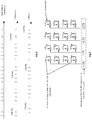
- the eNB may beamform the CSI-RS in the horizontal dimension in accordance with the received CSI in the vertical dimension, as shown in Fig.3 .
- the antennae in each group are configured to transmit a pilot signal for one port of the CSI-RS in the horizontal dimension.
- W(0), W(1), W(2) and W(3) are each a scalar, and each of them represents a weighting coefficient.
- W(0), W(1), W(2) and W(3) there are four antennae in each column, and the weighting coefficients for the four antennae are represented by W(0), W(1), W(2) and W(3) respectively.
- W(0), W(1), W(2) and W(3) may be of different values.
- the weighting coefficients of the antennae in different columns may be identical to each other, i.e., the weight vector W corresponding to the antennae in different columns may be [W(0), W(1), W(2), W(3)].
- W is a 4 ⁇ 1 vector, i.e., the weight vector W for the antennae in each column is a 4 ⁇ 1 vector [W(0), W(1), W(2), W(3)].
- the antennae in each column may correspond to this vector, so the vectors corresponding to the antennae in each column may be identical.
- the PMI information may be acquired from a corresponding codebook (a four-antenna codebook).
- the PMI information corresponds to the four antennae in the vertical dimension.
- the eNB may determine the beamforming matrix w in the vertical dimension from the corresponding codebook in accordance with the PMI information.
- the CSI-RSs in the horizontal dimension transmitted by the eNB to the UE in Step S105 may be S(0), S(1), S(2) and S(3), as shown in Fig.3 .
- Step S106 measuring, by the UE, the CSI-RS in the horizontal dimension transmitted by the eNB through the CSI-RS resource in the horizontal dimension, and transmitting, by the UE, the measured CSI in the horizontal dimension to the eNB.
- Step S107 receiving, by the eNB, the CSI in the horizontal dimension from the UE.
- the CSI in the horizontal dimension may be transmitted to the eNB using the method adopted in a conventional one-dimensional antenna system (e.g., an LTE Rel.12 system), without any modification.
- the UE may measure the CSI-RS in the horizontal dimension which has been bcamformcd in the vertical dimension, so the obtained CSI is just the final, overall 3D MIMO CSI.
- the eNB may directly use the final, overall CSI to perform link adaption.
- the UE may transmit the PMI information and the CQI information in the horizontal dimension to the eNB.
- the CQI information refers to the channel quality acquired after the CSI-RS in the horizontal dimension has been beamformed with the PMI information in the horizontal dimension.
- the CSI-RS in the horizontal dimension has been beamformed by the eNB with the PMI information in the vertical dimension, so the CQI information in the horizontal dimension from the UE has just been beamformed with the PMI information in both the horizontal dimension and the vertical dimension.
- Step S201 of determining beamforming array information in a first dimension including: Step S201 of determining beamforming array information in a first dimension; Step S202 of beamforming, in accordance with the beamforming array information in the first dimension, a pilot signal in a second dimension to be transmitted through a pilot resource in the second dimension pre-configured for a UE, and transmitting the beamformed pilot signal in the second dimension to the UE through the pilot resource in the second dimension; and Step S203 of receiving, from the UE, CSI in the second dimension obtained by the UE by measuring the beamformed pilot signal in the second dimension through the pilot resource in the second dimension pre-configured for the UE.
- the pilot signal in the second dimension which needs to be transmitted through the pilot resource in the second dimension pre-configured for the UE, may be beamformed in accordance with the beamforming array information in the first dimension, and then the beamformed pilot signal in the second dimension may be transmitted to the UE through the pilot resource in the second dimension, so that the UE may measure the pilot signal in the second dimension beamformed in accordance with the beamforming array information in the first dimension and the obtained CSI is just overall CSI for a final 3D MIMO antenna array.
- the network side device may directly schedule a link in accordance with the CSI in one dimension reported by the UE, rather than the CSI in two dimensions, so it is able to facilitate the CSI feedback and acquisition, and save the resources.
- the step of determining the beamforming array information in the first dimension includes: pre-configuring a pilot resource in the first dimension for the UE and notifying the UE of the pilot resource in the first dimension; transmitting a pilot signal in the first dimension to the UE through the pilot resource in the first dimension; and receiving, from the UE, CSI in the first dimension obtained by the UE by measuring the pilot signal in the first dimension through the pilot resource in the first dimension, and taking the CSI in the first dimension as the beamforming array information in the first dimension.
- the CSI in the first dimension includes Precoding Matrix Indicator (PMI) information.
- PMI Precoding Matrix Indicator
- the CSI in the first dimension further includes Rank Indicator (RI) information corresponding to the PMI information.
- RI Rank Indicator
- the CSI in the first dimension further includes CQI information obtained by the UE in accordance with the PMI information.
- the step of beamforming the pilot signal in the second dimension in accordance with the beamforming array information in the first dimension includes: beamforming the pilot signal in the second dimension through the CSI in the first dimension which is measured by the UE through the pilot resource in the first dimension and transmitted from the UE; or processing the CSI in the first dimension and beamforming the pilot signal in the second dimension in accordance with the processed CSI in the first dimension.
- the step of determining the beamforming array information in the first dimension includes measuring an uplink channel to determine the beamforming array information in the first dimension.
- the first dimension is perpendicular to the second dimension.
- the first dimension is a vertical dimension
- the second dimension is a horizontal dimension
- the pilot resource is a CSI-RS resource or a CRS resource.
- the present disclosure further provides in some embodiments a CSI feedback method at a UE side, including: Step S301 of determining a pilot resource in a second dimension pre-configured by a network side device for a UE; Step S302 of measuring a beamformed pilot signal in the second dimension transmitted by the network side device through the pilot resource in the second dimension, to acquire CSI in the second dimension, where the beamformed pilot signal in the second dimension is acquired by beamforming, by the network side device, a pilot signal in the second dimension to be transmitted through the pilot resource in the second dimension in accordance with beamforming array information in a first dimension; and Step S303 of transmitting the CSI in the second dimension to the network side device.
- the network side device may beamform the pilot signal in the second dimension, which needs to be transmitted through the pilot resource in the second dimension pre-configured for the UE, in accordance with the beamforming array information in the first dimension, and then transmit the beamformed pilot signal in the second dimension to the UE through the pilot resource in the second dimension, so that the UE may measure the pilot signal in the second dimension beamformed in accordance with the beamforming array information in the first dimension and the obtained CSI is just overall CSI for a final 3D MIMO antenna array.
- it is unnecessary for the UE to measure and report the excessive pilot resources thereby it is able to reduce the difficulty in processing the CSI progresses at a UE side, facilitate the CSI feedback and acquisition, and save the resources.
- the CSI feedback method further includes: determining, by the UE, a pilot resource in the first dimension pre-configured by the network side device for the UE: measuring a pilot signal in the first dimension transmitted through the pilot resource in the first dimension, so as to acquire CSI in the first dimension; and transmitting, by the UE, the CSI in the first dimension to the network side device.
- the CSI in the first dimension includes PMI information.
- the CSI in the first dimension further includes RI information corresponding to PMI information.
- the CSI in the first dimension further includes CQI information obtained by the UE in accordance with the PMI information.
- a CSI acquisition device at a network side, including: a first unit 11 configured to determine beamforming array information in a first dimension; a second unit 12 configured to beamform, in accordance with the beamforming array information in the first dimension, a pilot signal in a second dimension to be transmitted through a pilot resource in the second dimension pre-configured for a UE, and transmit the beamformed pilot signal in the second dimension to a UE through a pilot resource in the second dimension; and a third unit 13 configured to receive from the UE CSI in the second dimension obtained by the UE by measuring the beamformed pilot signal in the second dimension on the pilot resource in the second dimension pre-configured for the UE.
- the CSI feedback device further includes a fourth unit configured to pre-configure a pilot resource in the first dimension for the UE and notify the UE of the pilot resource in the first dimension, and transmit a pilot signal in the first dimension to the UE through the pilot resource in the first dimension.
- the first unit is further configured to receive, from the UE, CSI in the first dimension obtained by the UE by measuring the pilot signal in the first dimension through the pilot resource in the first dimension, and take the CSI in the first dimension as the beamforming array information in the first dimension.
- the CSI in the first dimension includes PMI information.
- the CSI in the first dimension further includes RI information corresponding to the PMI information.
- the CSI in the first dimension further includes CQI information obtained by the UE in accordance with the PMI information.
- the second unit is further configured to beamform the pilot signal in the second dimension directly through the CSI in the first dimension which is measured by the UE through the pilot resource in the first dimension and transmitted from the UE; or process the CSI in the first dimension and beamform the pilot signal in the second dimension in accordance with the processed CSI in the first dimension.
- the first unit is further configured to measure an uplink channel to determine the beamforming array information in the first dimension.
- a CSI feedback device at a UE side, including: a pilot resource determination unit 21 configured to determine a pilot resource in a second dimension pre-configured by a network side device for a UE; a measurement unit 22 configured to measure a beamformed pilot signal in the second dimension transmitted by the network side device through the pilot resource in the second dimension, to acquire CSI in the second dimension, where the beamformed pilot signal in the second dimension being a pilot signal acquired by beamforming, by the network side device, a pilot signal in the second dimension to be transmitted through the pilot resource in the second dimension in accordance with beamforming array information in a first dimension; and a transmission unit 23 configured to transmit the CSI in the second dimension to the network side device.
- a pilot resource determination unit 21 configured to determine a pilot resource in a second dimension pre-configured by a network side device for a UE
- a measurement unit 22 configured to measure a beamformed pilot signal in the second dimension transmitted by the network side device through the pilot resource in the second dimension, to acquire CSI in the second dimension, where
- the pilot resource determination unit 21 is further configured to determine a pilot resource in the first dimension prc-configurcd by the network side device for the UE.
- the measurement unit 22 is further configured to measure a pilot signal in the first dimension transmitted through the pilot resource in the first dimension, so as to acquire CSI in the first dimension.
- the transmission unit 23 is further configured to transmit the CSI in the first dimension to the network side device.
- the present disclosure further provides in some embodiments a base station for acquiring CSI, including a processor 500, a transceiver 510 and a memory 520.
- the processor 500 is configured to read programs stored in the memory 520, so as to: determine beamforming array information in a first dimension; beamform, in accordance with the beamforming array information in the first dimension, a pilot signal in a second dimension to be transmitted through a pilot resource in the second dimension pre-configured for a UE, , and transmit, through the transceiver 510, the beamformed pilot signal in the second dimension to the UE through the pilot resource in the second dimension; and receive, through the transceiver 510, from the UE CSI in the second dimension obtained by the UE by measuring the pilot signal in the second dimension through the pilot resource in the second dimension pre-configured for the UE.
- the transceiver 510 is configured to receive and transmit data under the control of the processor 500.
- the processor 500 is further configured to pre-configure a pilot resource in the first dimension for the UE and notify, through the transceiver 510, the UE of the pilot resource in the first dimension, and transmit, through the transceiver 510, a pilot signal in the first dimension to the UE through the pilot resource in the first dimension.
- the processor 500 is further configured to receive, through the transceiver 510, from the UE, CSI in the first dimension obtained by measuring the pilot signal in the first dimension through the pilot resource in the first dimension, and take the CSI in the first dimension as the beamforming array information in the first dimension.
- the processor 500 is further configured to: beamform the pilot signal in the second dimension directly through the CSI in the first dimension which is measured by the UE through the pilot resource in the first dimension and transmitted from the UE; or process the CSI in the first dimension and beamform the pilot signal in the second dimension in accordance with the processed CSI in the first dimension.
- the processor 500 is further configured to measure an uplink channel to determine the beamform array information in the first dimension.
- a bus architecture may include a number of buses and bridges connected to each other, so as to connect various circuits for one or more processors 500 and one or more memories 520.
- the bus architecture may be used to connect any other circuits, such as a circuit for a peripheral device, a circuit for a voltage stabilizer and a power management circuit.
- Bus interfaces are provided, and the transceiver 510 may consist of a plurality of elements, i.e., a transmitter and a receiver for communication with any other devices over a transmission medium.
- the processor 500 may take charge of managing the bus architecture as well general processings.
- the memory 520 may store data desired for the operation of the processor 500.
- the present disclosure further provides in some embodiments a UE for the CSI feedback at a UE side, including a processor 600, a transceiver 610 and a memory 620.
- the processor 600 is configured to read programs stored in the memory 620, so as to: determine a pilot resource in a second dimension pre-configured by a network side device for the UE; measure a beamformed pilot signal in the second dimension transmitted by the network side device through the pilot resource in the second dimension, to acquire CSI in the second dimension, where the beamformed pilot signal in the second dimension is acquired by beamforming, by the network side device, a pilot signal in the second dimension to be transmitted through the pilot resource in the second dimension in accordance with beamforming array information in a first dimension; and transmit, through the transceiver 610, the CSI in the second dimension to the network side device.
- the transceiver 610 is configured to receive and transmit data under the control of the processor 600.
- the processor 600 is further configured to: determine, a pilot resource in the first dimension pre-configured by the network side device for the UE: measure a pilot signal in the first dimension transmitted through the pilot resource in the first dimension, so as to acquire CSI in the first dimension; and transmit, through the transceiver 610, the CSI in the first dimension to the network side device.
- a bus architecture may include a number of buses and bridges connected to each other, so as to connect various circuits for one or more processors 600 and one or more memories 620.
- the bus architecture may be used to connect any other circuits, such as a circuit for a peripheral device, a circuit for a voltage stabilizer and a power management circuit.
- Bus interfaces are provided, and the transceiver 610 may consist of a plurality of elements, i.e., a transmitter and a receiver for communication with any other devices over a transmission medium.
- a user interface 630 may also be provided for devices which are to be arranged inside or outside the UE, and these devices may include but not limited to a keypad, a display, a speaker, a microphone and a joystick.
- the processor 600 may take charge of managing the bus architecture as well as general processings.
- the memory 620 may store data desired for the operation of the processor 600.
- the UE may measure the CSI-RS in the horizontal dimension and transmit the CSI in the horizontal dimension to the network side device.
- the CSI is the overall CSI acquired after the 3D MIMO beamforming operation, and it may be directly used for scheduling the link, i.e., it is unnecessary for the eNB to further process the CSI. Hence, it is able to reduce the CSI-RS overhead as well as the CSI feedback and measurement overhead.
- the eNB due to the very low requirement on the processing, it is able for the eNB to directly use the CSI in the horizontal dimension to perform the link adaption without further processing the CSI in the vertical dimension and the CSI in the horizontal dimension, so it is able to reduce the complexity of the eNB.
- the present disclosure may be provided as a method, a system or a computer program product, so the present disclosure may be in the form of full hardware embodiments, full software embodiments, or combinations thereof.
- the present disclosure may be in the form of a computer program product implemented on one or more computer-readable storage mediums (including but not limited to disk memory and optical memory) including computer-readable program codes.
- These computer program instructions may also be stored in a computer readable storage that may guide the computer or the other programmable data process devices to function in a certain way, so that the instructions stored in the computer readable storage may create a product including an instruction unit which achieves the functions assigned in one or more flows in the flow chart and/or one or more blocks in the block diagram.
- These computer program instructions may also be loaded in the computer or the other programmable data process devices, so that a series of operation steps are executed on the computer or the other programmable devices to create processes achieved by the computer. Therefore, the instructions executed in the computer or the other programmable devices provide the steps for achieving the function assigned in one or more flows in the flow chart and/or one or more blocks in the block diagram.
Landscapes
- Engineering & Computer Science (AREA)
- Signal Processing (AREA)
- Computer Networks & Wireless Communication (AREA)
- Physics & Mathematics (AREA)
- Mathematical Physics (AREA)
- Mobile Radio Communication Systems (AREA)
Claims (4)
- Verfahren zur Erfassung von Kanalzustandsinformationen, CSI, mit folgenden Schritten:Bestimmen von Strahlformungs-Array-Informationen in einer ersten Dimension (Schritt 201);Strahlformen eines Pilotsignals, das für Messungen in einer zweiten Dimension verwendet wird, entsprechend den Strahlformungs-Array-Informationen in der ersten Dimension und Senden des strahlgeformten Pilotsignals, das für die Messungen in der zweiten Dimension verwendet wird, an ein Benutzerendgerät, UE, durch eine Pilotressource in der zweiten Dimension (Schritt 202); undEmpfangen, von dem UE, von CSI in der zweiten Dimension, die von dem UE durch Messen des strahlgeformten Pilotsignals erhalten werden, welches für die Messungen in der zweiten Dimension verwendet wird (Schritt 203);wobei das Bestimmen der Strahlformungs-Array-Informationen in der ersten Dimension (Schritt 201) umfasst:Vorkonfigurieren einer Pilotressource in der ersten Dimension für das UE und Benachrichtigen des UE über die Pilotressource in der ersten Dimension;Senden eines Pilotsignals in der ersten Dimension an das UE durch die Pilotressource in der ersten Dimension; undEmpfangen, von dem UE, von CSI in der ersten Dimension, die von dem UE durch Messen des Pilotsignals in der ersten Dimension durch die Pilotressource in der ersten Dimension erhalten werden, und Verwenden der CSI in der ersten Dimension als die Strahlformungs-Array-Informationen in der ersten Dimension;wobei das Strahlformen des Pilotsignals, das für die Messungen in der zweiten Dimension verwendet wird, entsprechend den Strahlformungs-Array-Informationen in der ersten Dimension ferner umfasst:Verarbeiten der CSI in der ersten Dimension und Strahlformen des Pilotsignals, das für die Messungen in der zweiten Dimension verwendet wird, entsprechend den verarbeiteten CSI in der ersten Dimension;wobei die CSI in der ersten Dimension Vorcodierungsmatrixindikator-, PMI, Informationen umfasst sowie Kanalqualitätsindikator-, CQI, -Informationen, die von dem UE entsprechend den PMI-Informationen erhalten werden,dadurch gekennzeichnet, dass die CSI in der ersten Dimension ferner Rangindikator-, RI, Informationen umfassen, die den PMI-Informationen entsprechen.
- CSI-Erfassungsverfahren nach Anspruch 1, wobei die erste Dimension senkrecht zur zweiten Dimension ist.
- CSI-Erfassungsverfahren nach einem der Ansprüche 1 bis 2, wobei die Pilotressource eine Kanalzustandsinformations-Referenzsignal-, CSI-RS, Ressource oder eine gemeinsame Referenzsignal-, CRS, Ressource ist.
- Vorrichtung zur Erfassung von Kanalzustandsinformationen, CSI, die Folgendes aufweist:eine erste Einheit (11), die zum Bestimmen von Strahlformungs-Array-Informationen in einer ersten Dimension ausgebildet ist;eine zweite Einheit (12), die zum Strahlformen eines Pilotsignals, das für Messungen in einer zweiten Dimension verwendet wird, entsprechend den Strahlformungs-Array-Informationen in der ersten Dimension ausgebildet ist sowie zum Senden des strahlgeformten Pilotsignals, das für die Messungen in der zweiten Dimension verwendet wird, an ein Benutzerendgerät, UE, durch eine Pilotressource in der zweiten Dimension; undeine dritte Einheit (13), die zum Empfangen, von dem UE, von CSI in der zweiten Dimension ausgebildet ist, die von dem UE durch Messen des strahlgeformten Pilotsignals erhalten werden, welches für die Messungen in der zweiten Dimension verwendet wird,wobei die Vorrichtung ferner aufweist:eine vierte Einheit, die ausgebildet ist zum Vorkonfigurieren einer Pilotressource in der ersten Dimension für das UE und zum Benachrichtigen des UE über die Pilotressource in der ersten Dimension sowie zum Senden eines Pilotsignals in der ersten Dimension an das UE durch die Pilotressource in der ersten Dimension;wobei die erste Einheit (11) ferner ausgebildet ist zum Empfangen, von dem UE, von CSI in der ersten Dimension, die von dem UE durch Messen des Pilotsignals in der ersten Dimension durch die Pilotressource in der ersten Dimension erhalten werden, und zum Verwenden der CSI in der ersten Dimension als die Strahlformungs-Array-Informationen in der ersten Dimension;wobei die zweite Einheit (12) ferner ausgebildet ist zum Verarbeiten der CSI in der ersten Dimension und zum Strahlformen des Pilotsignals, das für die Messungen in der zweiten Dimension verwendet wird, entsprechend den verarbeiteten CSI in der ersten Dimension;wobei die CSI in der ersten Dimension Vorcodierungsmatrixindikator-, PMI, Informationen umfassen sowie Kanalqualitätsindikator-, CQI, -Informationen, die von dem UE entsprechend den PMI-Informationen erhalten werden, dadurch gekennzeichnet, dass die CSI in der ersten Dimension ferner Rangindikator-, RI, Informationen umfassen, die den PMI-Informationen entsprechen.
Applications Claiming Priority (2)
| Application Number | Priority Date | Filing Date | Title |
|---|---|---|---|
| CN201410575759.2A CN105530037B (zh) | 2014-10-24 | 2014-10-24 | 一种信道状态信息的反馈、获取方法及装置 |
| PCT/CN2015/090096 WO2016062178A1 (zh) | 2014-10-24 | 2015-09-21 | 一种信道状态信息的反馈、获取方法及装置 |
Publications (3)
| Publication Number | Publication Date |
|---|---|
| EP3211806A1 EP3211806A1 (de) | 2017-08-30 |
| EP3211806A4 EP3211806A4 (de) | 2017-11-01 |
| EP3211806B1 true EP3211806B1 (de) | 2020-11-11 |
Family
ID=55760272
Family Applications (1)
| Application Number | Title | Priority Date | Filing Date |
|---|---|---|---|
| EP15853245.7A Active EP3211806B1 (de) | 2014-10-24 | 2015-09-21 | Kanalstatusinformationsrückkopplung und erfassungsverfahren und -vorrichtung |
Country Status (5)
| Country | Link |
|---|---|
| US (1) | US10554275B2 (de) |
| EP (1) | EP3211806B1 (de) |
| CN (1) | CN105530037B (de) |
| TW (1) | TWI581655B (de) |
| WO (1) | WO2016062178A1 (de) |
Families Citing this family (9)
| Publication number | Priority date | Publication date | Assignee | Title |
|---|---|---|---|---|
| EP3637632B1 (de) | 2015-01-14 | 2021-09-08 | Telefonaktiebolaget LM Ericsson (publ) | Codebuch-subset-einschränkungssignalisierung |
| WO2017193278A1 (zh) * | 2016-05-10 | 2017-11-16 | 富士通株式会社 | Csi-rs的配置方法、csi的反馈方法、装置以及通信系统 |
| JP6731497B2 (ja) * | 2016-05-13 | 2020-07-29 | 華為技術有限公司Huawei Technologies Co.,Ltd. | チャネル状態情報報告方法、チャネル状態情報読み出し方法、及び関連装置 |
| US20200028599A1 (en) * | 2016-09-22 | 2020-01-23 | Huawei Technologies Co., Ltd. | Measurement Configuration Method and Apparatus |
| WO2018058621A1 (zh) * | 2016-09-30 | 2018-04-05 | 华为技术有限公司 | 一种波束赋形传输的方法及装置 |
| US10057145B2 (en) * | 2016-10-11 | 2018-08-21 | Bank Of America Corporation | Establishing an operative connection between a computing network and a third-party computing system for transmitting indications of process relationships |
| EP4016863A1 (de) | 2017-08-11 | 2022-06-22 | Telefonaktiebolaget LM Ericsson (publ) | Erweiterte strahlbasierte codebuch-untermengeneinschränkungssignalisierung |
| CN109842435A (zh) * | 2017-11-24 | 2019-06-04 | 上海诺基亚贝尔股份有限公司 | 一种用于执行预编码的方法和装置 |
| US11888562B2 (en) | 2020-01-03 | 2024-01-30 | Samsung Electronics Co., Ltd. | Method and apparatus for reciprocity based CSI-RS transmission and reception |
Citations (1)
| Publication number | Priority date | Publication date | Assignee | Title |
|---|---|---|---|---|
| US20130329664A1 (en) * | 2012-06-11 | 2013-12-12 | Samsung Electronics Co., Ltd. | Channel state information transmission/reception method and apparatus for use in wireless communication system |
Family Cites Families (17)
| Publication number | Priority date | Publication date | Assignee | Title |
|---|---|---|---|---|
| KR101715397B1 (ko) | 2009-04-22 | 2017-03-13 | 엘지전자 주식회사 | 무선 통신 시스템에서 참조신호 전송 장치 및 방법 |
| CN101877865B (zh) | 2009-04-30 | 2014-06-11 | 中兴通讯股份有限公司 | 发送测量参考信号的方法、系统以及基站和中继站 |
| KR101754970B1 (ko) | 2010-01-12 | 2017-07-06 | 삼성전자주식회사 | 무선 통신 시스템의 채널 상태 측정 기준신호 처리 장치 및 방법 |
| WO2011115421A2 (en) | 2010-03-17 | 2011-09-22 | Lg Electronics Inc. | Method and apparatus for providing channel state information-reference signal (csi-rs) configuration information in a wireless communication system supporting multiple antennas |
| US8675762B2 (en) | 2011-05-02 | 2014-03-18 | Alcatel Lucent | Method of transforming pre-coded signals for multiple-in-multiple-out wireless communication |
| CN102938688B (zh) | 2011-08-15 | 2015-05-27 | 上海贝尔股份有限公司 | 用于多维天线阵列的信道测量和反馈的方法和设备 |
| US8913682B2 (en) * | 2012-05-18 | 2014-12-16 | Samsung Electronics Co., Ltd. | Apparatus and method for channel state information codeword construction for a cellular wireless communication system |
| US9794817B2 (en) | 2012-06-24 | 2017-10-17 | Lg Electronics Inc. | Method and apparatus for reporting channel state information in wireless communication system |
| GB2507782B (en) * | 2012-11-09 | 2015-01-21 | Broadcom Corp | Methods and apparatus for wireless transmission |
| CN103840868A (zh) * | 2012-11-20 | 2014-06-04 | 电信科学技术研究院 | 一种指示和反馈信道质量信息的方法、设备及系统 |
| CN103840907B (zh) * | 2012-11-20 | 2018-06-05 | 电信科学技术研究院 | 一种传输导频信号和信号测量的方法、系统及设备 |
| US8976884B2 (en) * | 2012-12-20 | 2015-03-10 | Google Technology Holdings LLC | Method and apparatus for antenna array channel feedback |
| KR20150103046A (ko) * | 2013-01-02 | 2015-09-09 | 엘지전자 주식회사 | 하향링크 무선 신호를 수신하기 위한 방법 및 이를 위한 장치 |
| WO2014117352A1 (en) * | 2013-01-31 | 2014-08-07 | Qualcomm Incorporated | 3d mimo csi feedback based on virtual elevation ports |
| US10193665B2 (en) | 2013-03-21 | 2019-01-29 | Texas Instruments Incorporated | Reference signal for 3D MIMO in wireless communication systems |
| US10164693B2 (en) * | 2013-05-09 | 2018-12-25 | Intel IP Corporation | Reduction of buffer overflow |
| KR102064939B1 (ko) * | 2013-08-07 | 2020-01-13 | 삼성전자 주식회사 | 다수의 이차원 배열 안테나를 사용하는 이동통신 시스템에서의 피드백 송수신 방법 및 장치 |
-
2014
- 2014-10-24 CN CN201410575759.2A patent/CN105530037B/zh active Active
-
2015
- 2015-09-21 WO PCT/CN2015/090096 patent/WO2016062178A1/zh not_active Ceased
- 2015-09-21 EP EP15853245.7A patent/EP3211806B1/de active Active
- 2015-09-21 US US15/521,607 patent/US10554275B2/en active Active
- 2015-10-05 TW TW104132664A patent/TWI581655B/zh active
Patent Citations (1)
| Publication number | Priority date | Publication date | Assignee | Title |
|---|---|---|---|---|
| US20130329664A1 (en) * | 2012-06-11 | 2013-12-12 | Samsung Electronics Co., Ltd. | Channel state information transmission/reception method and apparatus for use in wireless communication system |
Also Published As
| Publication number | Publication date |
|---|---|
| WO2016062178A1 (zh) | 2016-04-28 |
| US10554275B2 (en) | 2020-02-04 |
| EP3211806A4 (de) | 2017-11-01 |
| CN105530037B (zh) | 2019-04-19 |
| TW201616903A (zh) | 2016-05-01 |
| CN105530037A (zh) | 2016-04-27 |
| TWI581655B (zh) | 2017-05-01 |
| US20170244459A1 (en) | 2017-08-24 |
| EP3211806A1 (de) | 2017-08-30 |
Similar Documents
| Publication | Publication Date | Title |
|---|---|---|
| EP3211806B1 (de) | Kanalstatusinformationsrückkopplung und erfassungsverfahren und -vorrichtung | |
| EP3270524B1 (de) | Hybrides strahlformendes übertragungsverfahren und netzwerkvorrichtung | |
| EP3267593B1 (de) | Kanalstatusinformationserfassungsverfahren und kanalstatusinformationsfeedbackverfahren und -vorrichtung | |
| EP3228021B1 (de) | Verfahren und vorrichtung zur abwärtsstreckensignalisierung für teilweise vorkodierte csi-rs- und csi-rückkopplung | |
| JP6594443B2 (ja) | 基地局及びプリコーディングマトリックス決定方法 | |
| JP6441243B2 (ja) | 無線通信システムにおいてチャネル状態情報報告方法及び装置 | |
| EP3331181B1 (de) | Kanalstatusinformationsrückkopplung und empfangsverfahren sowie vorrichtung | |
| CN107079308B (zh) | 基站和用户装置 | |
| EP3280070B1 (de) | Methode und vorrichtung zur erfassung und rückkopplung von kanalzustandsinformation | |
| US10291308B2 (en) | Channel state information feedback method, device and system | |
| US20190081669A1 (en) | Two-stage precoding method and apparatus | |
| US10840991B2 (en) | User equipment and method for selection of CSI reference signal and CSI reporting in a beam forming system with multiple beams | |
| KR20150003231A (ko) | 사용자당 앙각 mimo를 위한 피드백 방법론 | |
| US20180124624A1 (en) | Channel state information acquisition method and device | |
| CN106033990B (zh) | 一种信道状态信息反馈方法、获取方法及装置 | |
| WO2016207929A1 (ja) | 無線通信制御方法、無線通信システム、受信装置および送信装置 |
Legal Events
| Date | Code | Title | Description |
|---|---|---|---|
| STAA | Information on the status of an ep patent application or granted ep patent |
Free format text: STATUS: THE INTERNATIONAL PUBLICATION HAS BEEN MADE |
|
| PUAI | Public reference made under article 153(3) epc to a published international application that has entered the european phase |
Free format text: ORIGINAL CODE: 0009012 |
|
| STAA | Information on the status of an ep patent application or granted ep patent |
Free format text: STATUS: REQUEST FOR EXAMINATION WAS MADE |
|
| 17P | Request for examination filed |
Effective date: 20170502 |
|
| AK | Designated contracting states |
Kind code of ref document: A1 Designated state(s): AL AT BE BG CH CY CZ DE DK EE ES FI FR GB GR HR HU IE IS IT LI LT LU LV MC MK MT NL NO PL PT RO RS SE SI SK SM TR |
|
| AX | Request for extension of the european patent |
Extension state: BA ME |
|
| A4 | Supplementary search report drawn up and despatched |
Effective date: 20171004 |
|
| RIC1 | Information provided on ipc code assigned before grant |
Ipc: H04B 7/06 20060101AFI20170927BHEP Ipc: H04L 5/00 20060101ALI20170927BHEP |
|
| DAV | Request for validation of the european patent (deleted) | ||
| DAX | Request for extension of the european patent (deleted) | ||
| STAA | Information on the status of an ep patent application or granted ep patent |
Free format text: STATUS: EXAMINATION IS IN PROGRESS |
|
| 17Q | First examination report despatched |
Effective date: 20190111 |
|
| GRAP | Despatch of communication of intention to grant a patent |
Free format text: ORIGINAL CODE: EPIDOSNIGR1 |
|
| STAA | Information on the status of an ep patent application or granted ep patent |
Free format text: STATUS: GRANT OF PATENT IS INTENDED |
|
| INTG | Intention to grant announced |
Effective date: 20200610 |
|
| GRAS | Grant fee paid |
Free format text: ORIGINAL CODE: EPIDOSNIGR3 |
|
| GRAA | (expected) grant |
Free format text: ORIGINAL CODE: 0009210 |
|
| STAA | Information on the status of an ep patent application or granted ep patent |
Free format text: STATUS: THE PATENT HAS BEEN GRANTED |
|
| AK | Designated contracting states |
Kind code of ref document: B1 Designated state(s): AL AT BE BG CH CY CZ DE DK EE ES FI FR GB GR HR HU IE IS IT LI LT LU LV MC MK MT NL NO PL PT RO RS SE SI SK SM TR |
|
| REG | Reference to a national code |
Ref country code: GB Ref legal event code: FG4D |
|
| REG | Reference to a national code |
Ref country code: CH Ref legal event code: EP |
|
| REG | Reference to a national code |
Ref country code: AT Ref legal event code: REF Ref document number: 1334446 Country of ref document: AT Kind code of ref document: T Effective date: 20201115 |
|
| REG | Reference to a national code |
Ref country code: DE Ref legal event code: R096 Ref document number: 602015061983 Country of ref document: DE |
|
| REG | Reference to a national code |
Ref country code: IE Ref legal event code: FG4D |
|
| REG | Reference to a national code |
Ref country code: NL Ref legal event code: MP Effective date: 20201111 |
|
| REG | Reference to a national code |
Ref country code: AT Ref legal event code: MK05 Ref document number: 1334446 Country of ref document: AT Kind code of ref document: T Effective date: 20201111 |
|
| PG25 | Lapsed in a contracting state [announced via postgrant information from national office to epo] |
Ref country code: NO Free format text: LAPSE BECAUSE OF FAILURE TO SUBMIT A TRANSLATION OF THE DESCRIPTION OR TO PAY THE FEE WITHIN THE PRESCRIBED TIME-LIMIT Effective date: 20210211 Ref country code: FI Free format text: LAPSE BECAUSE OF FAILURE TO SUBMIT A TRANSLATION OF THE DESCRIPTION OR TO PAY THE FEE WITHIN THE PRESCRIBED TIME-LIMIT Effective date: 20201111 Ref country code: PT Free format text: LAPSE BECAUSE OF FAILURE TO SUBMIT A TRANSLATION OF THE DESCRIPTION OR TO PAY THE FEE WITHIN THE PRESCRIBED TIME-LIMIT Effective date: 20210311 Ref country code: RS Free format text: LAPSE BECAUSE OF FAILURE TO SUBMIT A TRANSLATION OF THE DESCRIPTION OR TO PAY THE FEE WITHIN THE PRESCRIBED TIME-LIMIT Effective date: 20201111 Ref country code: GR Free format text: LAPSE BECAUSE OF FAILURE TO SUBMIT A TRANSLATION OF THE DESCRIPTION OR TO PAY THE FEE WITHIN THE PRESCRIBED TIME-LIMIT Effective date: 20210212 |
|
| PG25 | Lapsed in a contracting state [announced via postgrant information from national office to epo] |
Ref country code: BG Free format text: LAPSE BECAUSE OF FAILURE TO SUBMIT A TRANSLATION OF THE DESCRIPTION OR TO PAY THE FEE WITHIN THE PRESCRIBED TIME-LIMIT Effective date: 20210211 Ref country code: SE Free format text: LAPSE BECAUSE OF FAILURE TO SUBMIT A TRANSLATION OF THE DESCRIPTION OR TO PAY THE FEE WITHIN THE PRESCRIBED TIME-LIMIT Effective date: 20201111 Ref country code: PL Free format text: LAPSE BECAUSE OF FAILURE TO SUBMIT A TRANSLATION OF THE DESCRIPTION OR TO PAY THE FEE WITHIN THE PRESCRIBED TIME-LIMIT Effective date: 20201111 Ref country code: LV Free format text: LAPSE BECAUSE OF FAILURE TO SUBMIT A TRANSLATION OF THE DESCRIPTION OR TO PAY THE FEE WITHIN THE PRESCRIBED TIME-LIMIT Effective date: 20201111 Ref country code: IS Free format text: LAPSE BECAUSE OF FAILURE TO SUBMIT A TRANSLATION OF THE DESCRIPTION OR TO PAY THE FEE WITHIN THE PRESCRIBED TIME-LIMIT Effective date: 20210311 Ref country code: AT Free format text: LAPSE BECAUSE OF FAILURE TO SUBMIT A TRANSLATION OF THE DESCRIPTION OR TO PAY THE FEE WITHIN THE PRESCRIBED TIME-LIMIT Effective date: 20201111 |
|
| REG | Reference to a national code |
Ref country code: LT Ref legal event code: MG9D |
|
| PG25 | Lapsed in a contracting state [announced via postgrant information from national office to epo] |
Ref country code: HR Free format text: LAPSE BECAUSE OF FAILURE TO SUBMIT A TRANSLATION OF THE DESCRIPTION OR TO PAY THE FEE WITHIN THE PRESCRIBED TIME-LIMIT Effective date: 20201111 |
|
| PG25 | Lapsed in a contracting state [announced via postgrant information from national office to epo] |
Ref country code: SK Free format text: LAPSE BECAUSE OF FAILURE TO SUBMIT A TRANSLATION OF THE DESCRIPTION OR TO PAY THE FEE WITHIN THE PRESCRIBED TIME-LIMIT Effective date: 20201111 Ref country code: RO Free format text: LAPSE BECAUSE OF FAILURE TO SUBMIT A TRANSLATION OF THE DESCRIPTION OR TO PAY THE FEE WITHIN THE PRESCRIBED TIME-LIMIT Effective date: 20201111 Ref country code: SM Free format text: LAPSE BECAUSE OF FAILURE TO SUBMIT A TRANSLATION OF THE DESCRIPTION OR TO PAY THE FEE WITHIN THE PRESCRIBED TIME-LIMIT Effective date: 20201111 Ref country code: LT Free format text: LAPSE BECAUSE OF FAILURE TO SUBMIT A TRANSLATION OF THE DESCRIPTION OR TO PAY THE FEE WITHIN THE PRESCRIBED TIME-LIMIT Effective date: 20201111 Ref country code: CZ Free format text: LAPSE BECAUSE OF FAILURE TO SUBMIT A TRANSLATION OF THE DESCRIPTION OR TO PAY THE FEE WITHIN THE PRESCRIBED TIME-LIMIT Effective date: 20201111 Ref country code: EE Free format text: LAPSE BECAUSE OF FAILURE TO SUBMIT A TRANSLATION OF THE DESCRIPTION OR TO PAY THE FEE WITHIN THE PRESCRIBED TIME-LIMIT Effective date: 20201111 |
|
| REG | Reference to a national code |
Ref country code: DE Ref legal event code: R081 Ref document number: 602015061983 Country of ref document: DE Owner name: DATANG MOBILE COMMUNICATIONS EQUIPMENT CO., LT, CN Free format text: FORMER OWNER: CHINA ACADEMY OF TELECOMMUNICATIONS TECHNOLOGY, BEIJING, CN |
|
| REG | Reference to a national code |
Ref country code: DE Ref legal event code: R097 Ref document number: 602015061983 Country of ref document: DE |
|
| REG | Reference to a national code |
Ref country code: GB Ref legal event code: 732E Free format text: REGISTERED BETWEEN 20210729 AND 20210804 |
|
| PG25 | Lapsed in a contracting state [announced via postgrant information from national office to epo] |
Ref country code: DK Free format text: LAPSE BECAUSE OF FAILURE TO SUBMIT A TRANSLATION OF THE DESCRIPTION OR TO PAY THE FEE WITHIN THE PRESCRIBED TIME-LIMIT Effective date: 20201111 |
|
| PLBE | No opposition filed within time limit |
Free format text: ORIGINAL CODE: 0009261 |
|
| STAA | Information on the status of an ep patent application or granted ep patent |
Free format text: STATUS: NO OPPOSITION FILED WITHIN TIME LIMIT |
|
| 26N | No opposition filed |
Effective date: 20210812 |
|
| PG25 | Lapsed in a contracting state [announced via postgrant information from national office to epo] |
Ref country code: NL Free format text: LAPSE BECAUSE OF FAILURE TO SUBMIT A TRANSLATION OF THE DESCRIPTION OR TO PAY THE FEE WITHIN THE PRESCRIBED TIME-LIMIT Effective date: 20201111 Ref country code: AL Free format text: LAPSE BECAUSE OF FAILURE TO SUBMIT A TRANSLATION OF THE DESCRIPTION OR TO PAY THE FEE WITHIN THE PRESCRIBED TIME-LIMIT Effective date: 20201111 Ref country code: IT Free format text: LAPSE BECAUSE OF FAILURE TO SUBMIT A TRANSLATION OF THE DESCRIPTION OR TO PAY THE FEE WITHIN THE PRESCRIBED TIME-LIMIT Effective date: 20201111 |
|
| PG25 | Lapsed in a contracting state [announced via postgrant information from national office to epo] |
Ref country code: SI Free format text: LAPSE BECAUSE OF FAILURE TO SUBMIT A TRANSLATION OF THE DESCRIPTION OR TO PAY THE FEE WITHIN THE PRESCRIBED TIME-LIMIT Effective date: 20201111 |
|
| PG25 | Lapsed in a contracting state [announced via postgrant information from national office to epo] |
Ref country code: ES Free format text: LAPSE BECAUSE OF FAILURE TO SUBMIT A TRANSLATION OF THE DESCRIPTION OR TO PAY THE FEE WITHIN THE PRESCRIBED TIME-LIMIT Effective date: 20201111 |
|
| REG | Reference to a national code |
Ref country code: CH Ref legal event code: PL |
|
| REG | Reference to a national code |
Ref country code: BE Ref legal event code: MM Effective date: 20210930 |
|
| PG25 | Lapsed in a contracting state [announced via postgrant information from national office to epo] |
Ref country code: IS Free format text: LAPSE BECAUSE OF FAILURE TO SUBMIT A TRANSLATION OF THE DESCRIPTION OR TO PAY THE FEE WITHIN THE PRESCRIBED TIME-LIMIT Effective date: 20210311 Ref country code: MC Free format text: LAPSE BECAUSE OF FAILURE TO SUBMIT A TRANSLATION OF THE DESCRIPTION OR TO PAY THE FEE WITHIN THE PRESCRIBED TIME-LIMIT Effective date: 20201111 |
|
| PG25 | Lapsed in a contracting state [announced via postgrant information from national office to epo] |
Ref country code: LU Free format text: LAPSE BECAUSE OF NON-PAYMENT OF DUE FEES Effective date: 20210921 Ref country code: IE Free format text: LAPSE BECAUSE OF NON-PAYMENT OF DUE FEES Effective date: 20210921 Ref country code: BE Free format text: LAPSE BECAUSE OF NON-PAYMENT OF DUE FEES Effective date: 20210930 |
|
| PG25 | Lapsed in a contracting state [announced via postgrant information from national office to epo] |
Ref country code: LI Free format text: LAPSE BECAUSE OF NON-PAYMENT OF DUE FEES Effective date: 20210930 Ref country code: CH Free format text: LAPSE BECAUSE OF NON-PAYMENT OF DUE FEES Effective date: 20210930 |
|
| PG25 | Lapsed in a contracting state [announced via postgrant information from national office to epo] |
Ref country code: HU Free format text: LAPSE BECAUSE OF FAILURE TO SUBMIT A TRANSLATION OF THE DESCRIPTION OR TO PAY THE FEE WITHIN THE PRESCRIBED TIME-LIMIT; INVALID AB INITIO Effective date: 20150921 |
|
| P01 | Opt-out of the competence of the unified patent court (upc) registered |
Effective date: 20230512 |
|
| PG25 | Lapsed in a contracting state [announced via postgrant information from national office to epo] |
Ref country code: CY Free format text: LAPSE BECAUSE OF FAILURE TO SUBMIT A TRANSLATION OF THE DESCRIPTION OR TO PAY THE FEE WITHIN THE PRESCRIBED TIME-LIMIT Effective date: 20201111 |
|
| PG25 | Lapsed in a contracting state [announced via postgrant information from national office to epo] |
Ref country code: MK Free format text: LAPSE BECAUSE OF FAILURE TO SUBMIT A TRANSLATION OF THE DESCRIPTION OR TO PAY THE FEE WITHIN THE PRESCRIBED TIME-LIMIT Effective date: 20201111 |
|
| PG25 | Lapsed in a contracting state [announced via postgrant information from national office to epo] |
Ref country code: MT Free format text: LAPSE BECAUSE OF FAILURE TO SUBMIT A TRANSLATION OF THE DESCRIPTION OR TO PAY THE FEE WITHIN THE PRESCRIBED TIME-LIMIT Effective date: 20201111 |
|
| PGFP | Annual fee paid to national office [announced via postgrant information from national office to epo] |
Ref country code: DE Payment date: 20250919 Year of fee payment: 11 |
|
| PGFP | Annual fee paid to national office [announced via postgrant information from national office to epo] |
Ref country code: GB Payment date: 20250919 Year of fee payment: 11 |
|
| PGFP | Annual fee paid to national office [announced via postgrant information from national office to epo] |
Ref country code: FR Payment date: 20250922 Year of fee payment: 11 |
|
| PG25 | Lapsed in a contracting state [announced via postgrant information from national office to epo] |
Ref country code: TR Free format text: LAPSE BECAUSE OF FAILURE TO SUBMIT A TRANSLATION OF THE DESCRIPTION OR TO PAY THE FEE WITHIN THE PRESCRIBED TIME-LIMIT Effective date: 20201111 |