EP3211864A1 - Interface de communication de champ avec une meilleure autoconfiguration - Google Patents
Interface de communication de champ avec une meilleure autoconfiguration Download PDFInfo
- Publication number
- EP3211864A1 EP3211864A1 EP16156980.1A EP16156980A EP3211864A1 EP 3211864 A1 EP3211864 A1 EP 3211864A1 EP 16156980 A EP16156980 A EP 16156980A EP 3211864 A1 EP3211864 A1 EP 3211864A1
- Authority
- EP
- European Patent Office
- Prior art keywords
- fci
- location
- network
- location identifier
- determining unit
- Prior art date
- Legal status (The legal status is an assumption and is not a legal conclusion. Google has not performed a legal analysis and makes no representation as to the accuracy of the status listed.)
- Withdrawn
Links
Images
Classifications
-
- H—ELECTRICITY
- H04—ELECTRIC COMMUNICATION TECHNIQUE
- H04L—TRANSMISSION OF DIGITAL INFORMATION, e.g. TELEGRAPHIC COMMUNICATION
- H04L41/00—Arrangements for maintenance, administration or management of data switching networks, e.g. of packet switching networks
- H04L41/12—Discovery or management of network topologies
-
- G—PHYSICS
- G05—CONTROLLING; REGULATING
- G05B—CONTROL OR REGULATING SYSTEMS IN GENERAL; FUNCTIONAL ELEMENTS OF SUCH SYSTEMS; MONITORING OR TESTING ARRANGEMENTS FOR SUCH SYSTEMS OR ELEMENTS
- G05B19/00—Program-control systems
- G05B19/02—Program-control systems electric
- G05B19/04—Program control other than numerical control, i.e. in sequence controllers or logic controllers
- G05B19/042—Program control other than numerical control, i.e. in sequence controllers or logic controllers using digital processors
- G05B19/0426—Programming the control sequence
-
- G—PHYSICS
- G05—CONTROLLING; REGULATING
- G05B—CONTROL OR REGULATING SYSTEMS IN GENERAL; FUNCTIONAL ELEMENTS OF SUCH SYSTEMS; MONITORING OR TESTING ARRANGEMENTS FOR SUCH SYSTEMS OR ELEMENTS
- G05B19/00—Program-control systems
- G05B19/02—Program-control systems electric
- G05B19/04—Program control other than numerical control, i.e. in sequence controllers or logic controllers
- G05B19/048—Monitoring; Safety
-
- H—ELECTRICITY
- H04—ELECTRIC COMMUNICATION TECHNIQUE
- H04L—TRANSMISSION OF DIGITAL INFORMATION, e.g. TELEGRAPHIC COMMUNICATION
- H04L61/00—Network arrangements, protocols or services for addressing or naming
- H04L61/50—Address allocation
- H04L61/5053—Lease time; Renewal aspects
-
- H—ELECTRICITY
- H04—ELECTRIC COMMUNICATION TECHNIQUE
- H04L—TRANSMISSION OF DIGITAL INFORMATION, e.g. TELEGRAPHIC COMMUNICATION
- H04L61/00—Network arrangements, protocols or services for addressing or naming
- H04L61/50—Address allocation
- H04L61/5092—Address allocation by self-assignment, e.g. picking addresses at random and testing if they are already in use
-
- H—ELECTRICITY
- H04—ELECTRIC COMMUNICATION TECHNIQUE
- H04L—TRANSMISSION OF DIGITAL INFORMATION, e.g. TELEGRAPHIC COMMUNICATION
- H04L67/00—Network arrangements or protocols for supporting network services or applications
- H04L67/50—Network services
- H04L67/52—Network services specially adapted for the location of the user terminal
-
- G—PHYSICS
- G05—CONTROLLING; REGULATING
- G05B—CONTROL OR REGULATING SYSTEMS IN GENERAL; FUNCTIONAL ELEMENTS OF SUCH SYSTEMS; MONITORING OR TESTING ARRANGEMENTS FOR SUCH SYSTEMS OR ELEMENTS
- G05B2219/00—Program-control systems
- G05B2219/20—Pc systems
- G05B2219/25—Pc structure of the system
- G05B2219/25062—Detect physical location of field device
-
- H—ELECTRICITY
- H04—ELECTRIC COMMUNICATION TECHNIQUE
- H04L—TRANSMISSION OF DIGITAL INFORMATION, e.g. TELEGRAPHIC COMMUNICATION
- H04L2101/00—Indexing scheme associated with group H04L61/00
- H04L2101/60—Types of network addresses
- H04L2101/69—Types of network addresses using geographic information, e.g. room number
-
- H—ELECTRICITY
- H04—ELECTRIC COMMUNICATION TECHNIQUE
- H04L—TRANSMISSION OF DIGITAL INFORMATION, e.g. TELEGRAPHIC COMMUNICATION
- H04L41/00—Arrangements for maintenance, administration or management of data switching networks, e.g. of packet switching networks
- H04L41/08—Configuration management of networks or network elements
- H04L41/085—Retrieval of network configuration; Tracking network configuration history
- H04L41/0853—Retrieval of network configuration; Tracking network configuration history by actively collecting configuration information or by backing up configuration information
- H04L41/0856—Retrieval of network configuration; Tracking network configuration history by actively collecting configuration information or by backing up configuration information by backing up or archiving configuration information
-
- H—ELECTRICITY
- H04—ELECTRIC COMMUNICATION TECHNIQUE
- H04L—TRANSMISSION OF DIGITAL INFORMATION, e.g. TELEGRAPHIC COMMUNICATION
- H04L67/00—Network arrangements or protocols for supporting network services or applications
- H04L67/01—Protocols
- H04L67/12—Protocols specially adapted for proprietary or special-purpose networking environments, e.g. medical networks, sensor networks, networks in vehicles or remote metering networks
-
- H—ELECTRICITY
- H04—ELECTRIC COMMUNICATION TECHNIQUE
- H04L—TRANSMISSION OF DIGITAL INFORMATION, e.g. TELEGRAPHIC COMMUNICATION
- H04L67/00—Network arrangements or protocols for supporting network services or applications
- H04L67/34—Network arrangements or protocols for supporting network services or applications involving the movement of software or configuration parameters
Definitions
- the invention relates to a field communication interface for an industrial control system with improved network autoconfiguration and to a corresponding management unit for such interfaces.
- field equipment In an industrial control system, field equipment is configured and controlled remotely through the network of the control system.
- the field equipment has only few, if any, manual controls (e.g. push buttons).
- a field communication interface, FCI enables the field equipment to participate in the network, so that the field equipment can perform its job under the control of the control system.
- the FCI In order to participate in the network, the FCI needs a valid network address. When a new FCI is installed, it has no way of knowing its initial network address.
- the FCI could provide a web-based configuration interface that could be accessed by connecting a service computer locally to the FCI via a wired or wireless service tool connection.
- An initial network address can also be automatically assigned by a centralized network unit using well-known network services such as DHCP.
- the FCI is then identified by the unique MAC address of its network interface.
- the control system then has no way of knowing which piece of field equipment is served by the FCI, so a fair amount of the configuration of the new FCI will still have to be done manually. Since MAC addresses are globally unique, when a defective FCI is replaced, the new FCI will have a different MAC address, and the manual configuration work will have to be redone.
- an improved FCI and a corresponding FCI management unit, are provided.
- the present invention provides a field communication interface, FCI, for interfacing field equipment with a network of an industrial control system.
- the field equipment may be any type of equipment that is used to interact with, or to monitor, the industrial process. It may, for example, be any suitable type of sensor that measures some physical quantity, such as a voltage, a current, a temperature, a force or a pressure. It may, for example, also be any suitable type of actor, such as a valve, a relay, a switch or a motor.
- the FCI comprises a network interface, which may be a wired or wireless interface.
- the network may be of any suitable type.
- the network is an Ethernet network, and most preferably, it is an industrial Ethernet network according to a Profinet standard.
- the network may employ any suitable protocol for communication between the entities of the industrial control system.
- the network employs the IP protocol, so that communication can be effected, for example, by means of TCP connections and UDP datagrams.
- An IP network may use IPv4 and/or IPv6 addresses, and these addresses may, for example, be private addresses valid only within the network of the industrial control system, addresses valid in a virtual private network that interconnects multiple sites, or globally routable addresses that are reachable from the Internet.
- the FCI further comprises a location determining unit.
- This location determining unit is configured to determine a location identifier that uniquely identifies the physical location of the FCI within the industrial control system and/or within the network.
- the FCI further comprises an address determining unit that is configured to determine a network address that is valid in the network of the industrial control system from the location identifier.
- FCIs are consumables that will have to be replaced multiple times during the life of the industrial plant.
- the network interface of the FCI contains a transceiver which has to provide a certain transmit power for transmission on a wired or wireless link. Where there is a high power, there is heat, and heat will inevitably cause a degradation of semiconductor components over time. Therefore, FCIs have a limited service life.
- the service life of the actual field equipment may be a lot longer: For example, power dissipation, and thus heat production, in a sensor may be a lot lower than in the transceiver of the FCI.
- Actors in the field equipment may use considerably higher power than the transceiver of the FCI, but those actors are usually powered with a far lesser duty cycle than the transceiver of the FCI.
- a valve actor may be active only a few times a day for a few seconds each.
- the components in actors may be less prone to progressive degradation by heat than the transceiver of the FCI.
- the FCIs will typically only be installed in a number of discrete places that are fixed during the design of the plant and will not change.
- the location determining unit of the new FCI when a defective FCI is replaced with a new one in the same physical location, the location determining unit of the new FCI will determine the same location identifier that the location determining unit of the old FCI had previously determined. Therefore, the address determining unit of the new FCI will assign the same network address to the new FCI that the address determining unit of the old FCI had assigned to the old FCI. Thus, the new FCI will automatically report to the network with the same initial network address as the old FCI had done. The replacement of the FCI does not entail a manual configuration of the initial network address anymore.
- the physical location of the FCI can be determined by any suitable means. The determination needs to be only exact enough so that all places in the industrial control system that are configured to receive a FCI can be distinguished from one another. Apart from that, the determination needs to be only reproducible enough so that when an old FCI is replaced with a new FCI, the new FCI will reliably be recognized to be in the same physical location.
- the location determining unit may comprise a geolocating unit that is configured to evaluate the physical location of the FCI from radio signals emitted by a plurality of terrestrial and/or orbiting transmitters.
- the radio signals of GPS, Galileo, Glonass or some other satellite based geolocation system may be evaluated.
- terrestrial transmitters may be used. For example, such transmitters may be installed indoors in a factory building to provide a short-range geolocation of FCIs within this building.
- the location determining unit is additionally configured to discretize the physical location obtained from the evaluation to an accuracy finer than half of the shortest distance between any two locations in the industrial control system that are adapted to receive a FCI.
- the location determining unit may comprise a mapping unit that maps a physical location to a location identifier based on whether the physical location is within a specific area assigned to the location identifier. Areas assigned to different location identifiers should then not overlap. For example, if there are several locations in the plant that may receive a FCI and no two of these locations are closer than 3 meters together, all physical locations within a circle with a diameter of 2.5 meters around a location that may receive a FCI may be assigned to the location identifier that corresponds to this one location.
- the location determining unit comprises an interrogating unit configured to interrogate a unique feature of the field equipment and/or a permanently installed mounting and termination unit, MTU, that receives and/or houses the field equipment.
- a plant typically comprises a plurality of discrete locations that may receive field equipment, and these locations are typically determined when the plant is designed and built. Even if the actual field equipment may need to be upgraded or replaced, once the MTU that receives and/or houses the field equipment is installed in one of the discrete locations, this may stay there permanently.
- the term "permanently installed” does not imply that the MTU is mounted in its place in a manner that cannot be released non-destructively. Rather, this term is to be construed to mean that it is unlikely that there will be a need to remove the MTU again during the life of the plant.
- the location determining unit is able to derive the desired location identifier from the unique feature.
- the unique feature may be used as the location identifier.
- a unique feature of the field equipment may be interrogated by the interrogating unit.
- the interrogating unit there may be a field equipment that has no MTU.
- the unique feature may be exploited in an analogous way.
- the only relevant difference between a unique feature of the MTU and a unique feature of the field equipment is that during the life of the plant, the field equipment is more likely to be replaced by a new one because it may comprise moving parts and other components that have a limited service life. However, as detailed before, the field equipment will have to be replaced far less often than the FCI.
- the unique feature may be a feature that has been applied to the MTU or to the field equipment on purpose. Such a feature may, for example, be a unique serial number or other code. However, the unique feature may also, for example, be a randomly varying feature that is created during manufacture of the MTU or of the field equipment. For example, there may be a random corrugation that creates a unique speckle pattern when irradiated with a laser beam from the interrogating unit.
- the interrogating unit comprises means to read the unique feature, and/or the location identifier, from a machine-readable data carrier affixed to the MTU and/or to the field equipment.
- the data carrier may take any suitable form.
- the unique feature, and/or the location identifier may, for example, be stored in a memory, such as a ROM or PROM, that can be read out using a wired connection. It may also, for example, be stored in a transponder that can be interrogated by means of radio waves, such as a RFID or NFC transponder.
- An optically readable representation of the unique feature and/or of the location identifier may also be used as a machine-readable data carrier.
- the FCI is further configured to receive configuration parameters for the FCI, and/or for the field equipment, from the industrial control system. Since there is a one-to-one correlation between the exact location of the FCI and the exact purpose that the FCI and the corresponding field equipment shall serve, there is also a one-to-one correlation between said exact location and the configuration parameters that the FCI, and/or the field equipment, need in order to start normal operations. Since the configuration parameters are set via the industrial control system, rather than by directly punching them into a keypad on the equipment itself, the configuration parameters that a FCI had are stored not only in the FCI itself, but also somewhere else in the industrial control system. Therefore, these parameters will still be available if the FCI is dead.
- the industrial control system may recognize that this FCI takes the place of the dead one and supply it with the correct configuration parameters. In this manner, when a FCI needs to be replaced, no local user interaction with the new FCI is required at all besides the physical replacement of the dead FCI.
- This automatic configuration may, for example, be implemented by means of an embodiment of the invention where the FCI further comprises a nonvolatile memory for storing the location identifier.
- the FCI is configured to, upon power-up of the FCI, compare the location identifier obtained by the location determining unit with the location identifier stored in the nonvolatile memory. What happens then is dependent on the outcome of this comparison.
- the nonvolatile memory contains no location identifier, this means that the FCI is a new FCI.
- the location identifier obtained by the location determining unit is then stored in the nonvolatile memory. Since the FCI is new and has not been previously configured, it is in need of a configuration.
- the location identifier obtained by the location determining unit differs from the location identifier stored in the nonvolatile memory, this means that the FCI had been previously used and configured in a different location. Since a different configuration will be required at the new location of this FCI, the old configuration is no longer usable.
- the FCI stores the newly obtained location identifier in the nonvolatile memory and disregards its previous configuration. It is in need for a new configuration.
- the FCI subsequently retrieves configuration parameters from the industrial control system. Except when a location is equipped with a FCI for the very first time, the FCI will take the place of a previous one, so a set of configuration parameters that correspond to the location of the FCI will be available in the system.
- additional checks may be implemented to verify that the configuration parameters are compatible with and sufficient for the new FCI. For example, an upgraded version of the FCI may have additional functionality that needs configuring, so a previous set of configuration parameters that is silent about this new functionality may not suffice for the new FCI to start normal operations. Therefore, when linking up with the network, the FCI may transmit additional information that allows to identify the FCI, such as device type, version information, or vendor.
- the FCI shall wait to be configured before starting normal operations.
- a communication or application engineer may enter the required information into the industrial control system, which will forward it to the FCI via the network.
- the FCI is reachable in the network under its network address that has been autoconfigured on the basis of its physical location.
- the comparison returns a match between the location identifier stored in the nonvolatile memory and the location identifier obtained by the location determining unit, then it is confirmed that the FCI is installed in the proper location and its present configuration is appropriate for this location. The FCI then starts normal operations. In this manner, an FCI will automatically resume normal operations after it has been power-cycled while remaining installed in the same place.
- an FCI that is in need for configuration may transmit its location identifier to an entity in the industrial control system that manages the configurations of FCIs and/or of field equipment. This is the most suitable key to look up whether a set of configuration parameters is available for a specific location.
- the address determining unit is additionally configured to biuniquely map the location identifier onto a network address. This means that a specific location identifier will result in one and only one network address being assigned, and that, in reverse, the location identifier will be uniquely derivable from the network address by other entities on the network. In this manner, there is no need to separately communicate the location identifier.
- Such a biunique mapping may, for example, be effected by appending the location identifier to an address prefix that is specific for the network, thereby forming a complete network address that is valid in the network.
- the company where the industrial control system is installed will at least have been assigned a /64 network, where the first 64 of the 128 bits that make up an IPv6 address identify the company network.
- the company may sub-divide this address space further into subnetworks. For example, the next 16 bits of the IPv6 address may identify one of 65.536 possible subnetworks within the company. One of these subnetworks may be the network of the industrial control system.
- the first 80 (64+16) bits are fixed because they identify this subnetwork.
- the remaining 48 bits can be filled with the location identifier, which allows for more than 1014 possible locations.
- the configuration of the FCI may include its final network address and other final communication relations according to the protocol used and the application needed in the industrial control system.
- the network address autoconfigured by the FCI may also be used as a permanent network address, depending on the layout of the network.
- the FCI may be made to communicate its location identifier by sending an "identification" command from the industrial control system, or issuing such a command directly on the FCI, for example, by means of a push button.
- the invention also provides a FCI management unit for an industrial control system where field equipment is installable in a plurality of discrete locations. At least one field equipment is interfaced with the network of the industrial control system by means of a FCI according to the invention.
- the FCI management unit comprises a database that is configured to hold a set of configuration parameters for every one of the discrete locations. This database is searchable by the location identifier that the location determining unit in the FCI is configured to determine.
- configuration information in a central management system was usually tied to a unique hardware address of equipment, such as the MAC address of an Ethernet network interface. Since the network interface, of all things, is the component that will have to be replaced fairly often during the life of the plant, the organization of configuration information by hardware address resulted in a lot of redundant manual configuration work having to be redone. The new organization by location identifier therefore greatly facilitates the replacement an FCI by a new one.
- the database may additionally hold any other suitable information. For example, it may store an indication whether the FCI management unit has already been contacted by a FCI at each location. For example, if the FCI management unit encounters a location identifier for the first time, it may determine that the FCI at the corresponding location is in need for configuration, and propagate the FCI into a device life list for further engineering work. Once the FCI has been properly engineered and configured, the information associated with the location in the database may be enriched with additional information, such as a tag name or label that describes the FCI.
- the invention provides at least the following business benefits:
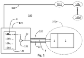
- Figure 1 shows an embodiment of the industrial control system 100.
- the system 100 comprises four discrete locations 101a-101d in which field equipment 2 is installable.
- the locations 101a-101d are all connected to the central FCI management unit 110 via a network 120.
- a field equipment 2 is installed and interfaced to the network 120 via its FCI 1 .
- the FCI 1 reports its location identifier 1a to the FCI management unit 110 via the network 120.
- the FCI management unit 110 comprises a database 130.
- the database 130 holds a set of configuration parameters 8.
- the database is searchable 135 by means of the location identifier 1 a.
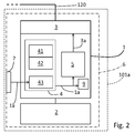
- FIG. 2 explains in detail how the FCI 1 is enabled, by the present invention, to obtain its location identifier 1a and a network address 3a, so that it can participate in the network 120 in the first place and communicate with the FCI management unit 110 without prior user intervention.
- the FCI 1 comprises a location determining unit 4 that has two ways of determining the location identifier 1a.
- the location determining unit 4 comprises a geolocating unit 41 that determines the exact coordinates of the location where the FCI 1 is installed by using GPS.
- the coordinates are passed on to a mapping unit 42, which maps the coordinates to a location identifier 1a.
- the mapping unit 42 determines that the coordinates are within the area assigned to the location 101 a, so the mapping unit 42 outputs the location identifier 1 a that corresponds to the location 101a.
- the location determining unit 4 comprises an interrogating unit 43 that can read out the location identifier 1a from a machine readable data carrier 7.
- the data carrier 7 is affixed to the mounting and termination unit, MTU, 6 that houses both the FCI and the attached field equipment 2. Since the MTU 6 contains no mechanical or electronic components that are subject to wear and tear, it can be permanently installed at the location 101 a.
- the location identifier 1a is passed on to the address determining unit 5.
- the address determining unit 5 appends the location identifier 1a to an address prefix that is specific for the network 120 to form a network address 3a that is valid in the network 120.
- the network address 3a is passed on to the network interface 3 that connects the FCI 1 to the network 120.
- the location identifier 1a is compared to a value that is stored in a nonvolatile memory 9 when the FCI 1 is powered up. If the location identifier 1a that has been freshly determined by the location determining unit matches the value that is stored in the nonvolatile memory 9, it is deemed that the FCI 1 is still installed in the same location where it was when it was last powered off. The FCI 1 can start normal operations with its present configuration. If the freshly determined location identifier 1a differs from the value stored in the nonvolatile memory 9, it is deemed that the location of the FCI 1 has changed. Consequently, the present configuration of the FCI 1 is deemed to be invalid, and new configuration parameters 8 are obtained from the FCI management unit 110.
Landscapes
- Engineering & Computer Science (AREA)
- Computer Networks & Wireless Communication (AREA)
- Signal Processing (AREA)
- Physics & Mathematics (AREA)
- General Physics & Mathematics (AREA)
- Automation & Control Theory (AREA)
- Small-Scale Networks (AREA)
Priority Applications (3)
| Application Number | Priority Date | Filing Date | Title |
|---|---|---|---|
| EP16156980.1A EP3211864A1 (fr) | 2016-02-23 | 2016-02-23 | Interface de communication de champ avec une meilleure autoconfiguration |
| CN201710097171.4A CN107105068B (zh) | 2016-02-23 | 2017-02-22 | 现场通信接口装置和现场通信接口管理设备 |
| US15/438,782 US20170242418A1 (en) | 2016-02-23 | 2017-02-22 | Field communication interface with improved autoconfiguration |
Applications Claiming Priority (1)
| Application Number | Priority Date | Filing Date | Title |
|---|---|---|---|
| EP16156980.1A EP3211864A1 (fr) | 2016-02-23 | 2016-02-23 | Interface de communication de champ avec une meilleure autoconfiguration |
Publications (1)
| Publication Number | Publication Date |
|---|---|
| EP3211864A1 true EP3211864A1 (fr) | 2017-08-30 |
Family
ID=55442669
Family Applications (1)
| Application Number | Title | Priority Date | Filing Date |
|---|---|---|---|
| EP16156980.1A Withdrawn EP3211864A1 (fr) | 2016-02-23 | 2016-02-23 | Interface de communication de champ avec une meilleure autoconfiguration |
Country Status (3)
| Country | Link |
|---|---|
| US (1) | US20170242418A1 (fr) |
| EP (1) | EP3211864A1 (fr) |
| CN (1) | CN107105068B (fr) |
Cited By (2)
| Publication number | Priority date | Publication date | Assignee | Title |
|---|---|---|---|---|
| WO2019108948A1 (fr) | 2017-12-01 | 2019-06-06 | Honeywell International Inc. | Établissement dynamique d'une communication entre un équipement mobile et un contrôleur de processus |
| EP4246912A1 (fr) * | 2022-03-15 | 2023-09-20 | Sony Group Corporation | Procédé, système et dispositif d'intégration de dispositif de remplacement |
Families Citing this family (2)
| Publication number | Priority date | Publication date | Assignee | Title |
|---|---|---|---|---|
| EP4155845B1 (fr) * | 2021-09-24 | 2023-11-01 | Sick Ag | Procédé de configuration d'un appareil d'une machine industrielle |
| EP4550743A1 (fr) * | 2023-11-02 | 2025-05-07 | Abb Schweiz Ag | Configuration de réseau dans des systèmes d'automatisation industrielle |
Citations (5)
| Publication number | Priority date | Publication date | Assignee | Title |
|---|---|---|---|---|
| WO2002096041A1 (fr) * | 2001-05-22 | 2002-11-28 | Kai Mustonen | Utilisation des informations sur l'emplacement geographique dans l'adressage ip |
| US6782436B1 (en) * | 2000-04-21 | 2004-08-24 | Richard A. Baker | Method and apparatus for locating devices within a network system |
| WO2006008522A1 (fr) * | 2004-07-21 | 2006-01-26 | Norgren Limited | Adressage ip |
| US20080008179A1 (en) * | 2006-07-07 | 2008-01-10 | Liren Chen | Geolocation-based addressing method for IPv6 addresses |
| US20150264010A1 (en) * | 2014-03-11 | 2015-09-17 | Electronics And Telecommunications Research Institute | Internet protocol version 6 address configuration method |
Family Cites Families (3)
| Publication number | Priority date | Publication date | Assignee | Title |
|---|---|---|---|---|
| US7653037B2 (en) * | 2005-09-28 | 2010-01-26 | Qualcomm Incorporated | System and method for distributing wireless network access parameters |
| GB2512999B (en) * | 2013-03-15 | 2020-09-23 | Fisher Rosemount Systems Inc | Method and apparatus for seamless state transfer between user interface devices in a mobile control room |
| CN104168341B (zh) * | 2014-08-15 | 2018-01-19 | 北京百度网讯科技有限公司 | Ip地址的定位方法和cdn调度方法以及装置 |
-
2016
- 2016-02-23 EP EP16156980.1A patent/EP3211864A1/fr not_active Withdrawn
-
2017
- 2017-02-22 US US15/438,782 patent/US20170242418A1/en not_active Abandoned
- 2017-02-22 CN CN201710097171.4A patent/CN107105068B/zh active Active
Patent Citations (5)
| Publication number | Priority date | Publication date | Assignee | Title |
|---|---|---|---|---|
| US6782436B1 (en) * | 2000-04-21 | 2004-08-24 | Richard A. Baker | Method and apparatus for locating devices within a network system |
| WO2002096041A1 (fr) * | 2001-05-22 | 2002-11-28 | Kai Mustonen | Utilisation des informations sur l'emplacement geographique dans l'adressage ip |
| WO2006008522A1 (fr) * | 2004-07-21 | 2006-01-26 | Norgren Limited | Adressage ip |
| US20080008179A1 (en) * | 2006-07-07 | 2008-01-10 | Liren Chen | Geolocation-based addressing method for IPv6 addresses |
| US20150264010A1 (en) * | 2014-03-11 | 2015-09-17 | Electronics And Telecommunications Research Institute | Internet protocol version 6 address configuration method |
Non-Patent Citations (1)
| Title |
|---|
| MARKUS RENTSCHLER: "Faulty device replacement for industrial networks", INDUSTRIAL INFORMATICS (INDIN), 2012 10TH IEEE INTERNATIONAL CONFERENCE ON, IEEE, 25 July 2012 (2012-07-25), pages 57 - 62, XP032235272, ISBN: 978-1-4673-0312-5, DOI: 10.1109/INDIN.2012.6301147 * |
Cited By (4)
| Publication number | Priority date | Publication date | Assignee | Title |
|---|---|---|---|---|
| WO2019108948A1 (fr) | 2017-12-01 | 2019-06-06 | Honeywell International Inc. | Établissement dynamique d'une communication entre un équipement mobile et un contrôleur de processus |
| EP3718291A4 (fr) * | 2017-12-01 | 2021-08-18 | Honeywell International Inc. | Établissement dynamique d'une communication entre un équipement mobile et un contrôleur de processus |
| EP4246912A1 (fr) * | 2022-03-15 | 2023-09-20 | Sony Group Corporation | Procédé, système et dispositif d'intégration de dispositif de remplacement |
| US12474933B2 (en) | 2022-03-15 | 2025-11-18 | Sony Group Corporation | Method, system, and device for integrating replacement device |
Also Published As
| Publication number | Publication date |
|---|---|
| US20170242418A1 (en) | 2017-08-24 |
| CN107105068A (zh) | 2017-08-29 |
| CN107105068B (zh) | 2020-12-25 |
Similar Documents
| Publication | Publication Date | Title |
|---|---|---|
| US20170242418A1 (en) | Field communication interface with improved autoconfiguration | |
| EP2430503B1 (fr) | Méthode d'évaluation d'un emplacement potentiel pour ajouter un appareil de terrain sans fil dans un réseau existant | |
| CN107006106B (zh) | 用于建立和操作照明设备网络的方法 | |
| US20200387136A1 (en) | Method and cloud gateway for monitoring an automated facility | |
| US20150066979A1 (en) | Device address management in an automation control system | |
| US20080234837A1 (en) | Configuration Of Wireless Field Devices For Process Control Plants | |
| EP1862037A1 (fr) | Mise en service de dispositifs reseau sans fil conformement a un plan d'installation | |
| WO2001082032A2 (fr) | Adressage de reseau fonde sur l'emplacement physique des sites d'un dispositif de reseau | |
| EP2279591A2 (fr) | Procédé de mise en service d'un agencement de dispositif | |
| CN112738658B (zh) | 对讲系统的配置方法、装置、对讲终端和配置服务器 | |
| CN110267411A (zh) | 用于控制灯、特别是路灯的控制模块以及灯网络 | |
| CN106936895A (zh) | 一种云服务器、扫地机和扫地机控制系统 | |
| EP3018497B1 (fr) | Procédé de détection de tremblements de terre et de localisation d'épicentres au moyen d'un réseau de lumières | |
| JP6873118B2 (ja) | 位置特定システムを備える飲料調製マシン | |
| JP2019534462A (ja) | ビルオートメーションシステム | |
| US20180132339A1 (en) | Method for the operation and expansion of a network of lights | |
| CN102594639B (zh) | 现场设备在配线系统中的集成方法 | |
| US20150092226A1 (en) | Systems and Methods for Location-Aware Imaging Devices | |
| JP6008411B2 (ja) | 機器管理装置、機器管理システム、機器管理方法及びプログラム | |
| US20160205721A1 (en) | Positioning system leveraged for installation and commissioning | |
| CN113300887A (zh) | 采集数据获取方法、装置、系统及存储介质 | |
| JP2006048459A (ja) | 無線データ通信システム | |
| US9642111B2 (en) | Method and system for communicating between a first item of equipment and one or more other items of equipment | |
| EP3516461B1 (fr) | Système d'automatisation de construction avec balise de mise en service | |
| US9098602B2 (en) | Storage of a desired address in a device of a control system |
Legal Events
| Date | Code | Title | Description |
|---|---|---|---|
| PUAI | Public reference made under article 153(3) epc to a published international application that has entered the european phase |
Free format text: ORIGINAL CODE: 0009012 |
|
| AK | Designated contracting states |
Kind code of ref document: A1 Designated state(s): AL AT BE BG CH CY CZ DE DK EE ES FI FR GB GR HR HU IE IS IT LI LT LU LV MC MK MT NL NO PL PT RO RS SE SI SK SM TR |
|
| AX | Request for extension of the european patent |
Extension state: BA ME |
|
| 17P | Request for examination filed |
Effective date: 20180220 |
|
| RBV | Designated contracting states (corrected) |
Designated state(s): AL AT BE BG CH CY CZ DE DK EE ES FI FR GB GR HR HU IE IS IT LI LT LU LV MC MK MT NL NO PL PT RO RS SE SI SK SM TR |
|
| 17Q | First examination report despatched |
Effective date: 20180312 |
|
| STAA | Information on the status of an ep patent application or granted ep patent |
Free format text: STATUS: THE APPLICATION HAS BEEN WITHDRAWN |
|
| 18W | Application withdrawn |
Effective date: 20190502 |