EP3212344B1 - Drahtziehanlage zum drahtziehen eines metalldrahtes, eines walzdrahts oder eines streifens - Google Patents
Drahtziehanlage zum drahtziehen eines metalldrahtes, eines walzdrahts oder eines streifens Download PDFInfo
- Publication number
- EP3212344B1 EP3212344B1 EP15805265.4A EP15805265A EP3212344B1 EP 3212344 B1 EP3212344 B1 EP 3212344B1 EP 15805265 A EP15805265 A EP 15805265A EP 3212344 B1 EP3212344 B1 EP 3212344B1
- Authority
- EP
- European Patent Office
- Prior art keywords
- wiredrawing
- drives
- line
- machine
- motors
- Prior art date
- Legal status (The legal status is an assumption and is not a legal conclusion. Google has not performed a legal analysis and makes no representation as to the accuracy of the status listed.)
- Not-in-force
Links
Images
Classifications
-
- B—PERFORMING OPERATIONS; TRANSPORTING
- B21—MECHANICAL METAL-WORKING WITHOUT ESSENTIALLY REMOVING MATERIAL; PUNCHING METAL
- B21C—MANUFACTURE OF METAL SHEETS, WIRE, RODS, TUBES, PROFILES OR LIKE SEMI-MANUFACTURED PRODUCTS OTHERWISE THAN BY ROLLING; AUXILIARY OPERATIONS USED IN CONNECTION WITH METAL-WORKING WITHOUT ESSENTIALLY REMOVING MATERIAL
- B21C1/00—Manufacture of metal sheets, wire, rods, tubes or like semi-manufactured products by drawing
-
- B—PERFORMING OPERATIONS; TRANSPORTING
- B21—MECHANICAL METAL-WORKING WITHOUT ESSENTIALLY REMOVING MATERIAL; PUNCHING METAL
- B21C—MANUFACTURE OF METAL SHEETS, WIRE, RODS, TUBES, PROFILES OR LIKE SEMI-MANUFACTURED PRODUCTS OTHERWISE THAN BY ROLLING; AUXILIARY OPERATIONS USED IN CONNECTION WITH METAL-WORKING WITHOUT ESSENTIALLY REMOVING MATERIAL
- B21C1/00—Manufacture of metal sheets, wire, rods, tubes or like semi-manufactured products by drawing
- B21C1/02—Drawing metal wire or like flexible metallic material by drawing machines or apparatus in which the drawing action is effected by drums
- B21C1/04—Drawing metal wire or like flexible metallic material by drawing machines or apparatus in which the drawing action is effected by drums with two or more dies operating in series
-
- B—PERFORMING OPERATIONS; TRANSPORTING
- B21—MECHANICAL METAL-WORKING WITHOUT ESSENTIALLY REMOVING MATERIAL; PUNCHING METAL
- B21C—MANUFACTURE OF METAL SHEETS, WIRE, RODS, TUBES, PROFILES OR LIKE SEMI-MANUFACTURED PRODUCTS OTHERWISE THAN BY ROLLING; AUXILIARY OPERATIONS USED IN CONNECTION WITH METAL-WORKING WITHOUT ESSENTIALLY REMOVING MATERIAL
- B21C1/00—Manufacture of metal sheets, wire, rods, tubes or like semi-manufactured products by drawing
- B21C1/16—Metal drawing by machines or apparatus in which the drawing action is effected by means other than drums, e.g. by a longitudinally-moved carriage pulling or pushing the work or stock for making metal sheets, rods or tubes
- B21C1/20—Metal drawing by machines or apparatus in which the drawing action is effected by means other than drums, e.g. by a longitudinally-moved carriage pulling or pushing the work or stock for making metal sheets, rods or tubes from stock of essentially unlimited length
Definitions
- the present invention relates to a wiredrawing line for wiredrawing a metal wire, wire rod or strip.
- a wiredrawing line typically comprises, in the following order, a wiredrawing machine, which is designed to carry out a constant-volume deformation on a metal wire by drawing it through a sequence of dies in order to obtain a wire with a smaller cross-section, an annealing furnace, which carries out a thermal treatment on the hard-drawn wire delivered by the wiredrawing machine in order to recover at least part of the resistance and ductility features of the metal making up the wire, and a spooler to wind the annealed wire around a spool.
- the annealing furnace is absent or not used, so as to obtain, at the end of the process, spools with a simple hard-drawn wire.
- the wiredrawing line is a multi-wire line, then it comprises different spoolers provided with respective spools or it comprises a collection creel comprising different spools.
- the wiredrawing machine comprises a plurality of drawing rings and the annealing furnace comprises a plurality of idler rollers and at least one drawing ring.
- the drawing rings, the spools of the spooler and, if provided, the idler rollers are moved, by means of suitable transmission systems, by induction motors. Each one of these motors is controlled by a respective drive. If the wiredrawing line is used to draw wires with a large diameter, the motors coupled with the drawing rings have a great power, for example up to 80 KW and, as a consequence, the relative drives are large and dissipate a lot of heat.
- all drives are housed in one single box arranged on the outside of the wiredrawing line, namely resting on the ground close to the wiredrawing line.
- the drives comprise respective DC/AC inverters, which are supplied with power by a power supply means housed in the external box.
- Each drive is connected to the respective motor by means of a respective shielded power cable.
- the presence of the external box has clear drawbacks.
- the external box has a large imprint on the ground, which complicates the logistics of the site where the wire drawing line is installed.
- the power cables are very long (namely, different metres long), so as to cause power losses and, in the special case of use of AC motors, remarkable electromagnetic troubles.
- the existence of the external box which must be installed separately from the other parts of the wiredrawing line, increases building and installation costs of the entire line, as suitable channels or conduits must be built and installed in order to allow the cables to go from the external box to the wiredrawing line.
- the object of the present invention is to provide a wiredrawing line having an electric architecture that is not affected by the aforementioned drawbacks and, at the same time, can be obtained in a simple and low-cost manner.
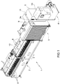
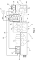
- number 1 generically indicates, as a whole, a multi-wire wiredrawing line according to the present invention.
- the wiredrawing line 1 comprises, arranged in the following order according to a wiredrawing direction T, a multi-wire wiredrawing machine 2, which receives a plurality of metal wires and carries out a wiredrawing thereof so as to reduce their cross-section, an annealing furnace 3, which receives hard-drawn wires from the wiredrawing machine 2 and carries out a direct current resistance annealing of the wires, and a spooler 4, which is designed to wind the annealed wires in respective spools.
- the annealing furnace 3 comprises a control board 5, which houses known electric apparatuses used to generate the so-called annealing voltage.
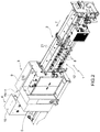
- the wiredrawing line 1 is shown not in use, namely it is shown without raw wires at the input of the wiredrawing machine 2 and without the annealed wires at the output 3a ( figure 1 ) of the annealing furnace 3, namely at the inlet 4a ( figure 2 ) of the spooler 4.
- the wiredrawing machine 2 comprises a plurality of drawing rings 6 ( figure 1 ), which rotate in a synchronized manner so as to draw the wires through a plurality of dies 7.
- the drawing rings 6 are caused to rotate by one or more induction motors 8 (in the example of figure 1 there are three of them) by means of a gear transmission system, which is known per se and, therefore, it is not shown in the figures.
- Part of each one of the motors 8 projects from a rear side 12 of the wiredrawing machine 2, namely from a side that is substantially parallel to the wiredrawing direction T, so as not to change the imprint of the wiredrawing machine 2 on the ground.
- the annealing furnace 3 and the spooler 4 comprise respective protection casings 9 and 10.
- the control board 5 is mounted on a lateral wall 11 of the protection casing 9, namely on a wall that is transverse to the wiredrawing direction T, so as not to change the imprint of the wiredrawing line 1 on the ground transversely to the wiredrawing direction T.
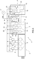
- the annealing furnace 3 comprises, housed on the inside of its protection casing, two idler rollers 13, a drawing ring 14 and three induction motors 15, which are designed to cause the rotation of a respective one of said idler rollers 13 and drawing ring 14.
- the control board 5 houses a power supply stage 16, which is of a known type and is designed to turn a three-phase voltage Uac provided by a three-phase source 17 into a direct current intermediate-volt voltage Udc, and subsequent voltage transformation stages, which are known per se and are indicated, as a whole, with number 18, to turn the intermediate voltage Udc into a direct current low-volt voltage Uann to be applied to the wire for its annealing.
- the intermediate voltage Udc has an amplitude ranging from 500 to 1000 V.
- the annealing voltage Uann has an amplitude that can be modulated in a known manner in an interval ranging from 0 to 110 V.
- the maximum level of the annealing voltage Uann depends on the type of metal of the wires to be annealed, on the geometry of the annealing furnace 3 and on the maximum feeding speed of the wires in the wiredrawing line 1.
- the spooler 4 comprises, housed on the inside of its protection casing 10, a plurality of spools 19, only two of them being shown in the figure for the sake of simplicity, and a plurality of induction motors 20, each designed to cause the rotation of a respective spool 19.
- the motors 8, 15 and 20 are controlled by respective drives 21, 22 and 23, each one of them being of the type comprising at least one DC/AC inverter.
- the drives 21, 22 and 23 are mounted on board the wiredrawing line 1 - in particular on board the respective motors 8, 15 and 20 - and are supplied with power by a single direct current voltage bus, or simply DC bus 24 ( figure 3 ), which is connected to the output of the power supply stage 16 and is mounted along - and on board - the wiredrawing line 1 so as to be able to reach all the drives 21-23.
- Figure 2 only shows the motors 8 and the drives 21 of the wiredrawing machine 2.
- the DC bus 24 comprises a first part mounted along the wiredrawing machine 2, a second part mounted along the annealing furnace 3 and a third part mounted along the spooler 4.
- the power cables (not shown) connecting the drives 21, 22 and 23 to the respective motors 8, 15 and 20 are very short and do not need a special shielding.
- the drives 21-23 are controlled, by means of a communication bus 25 mounted along - and on board - the wiredrawing line 1, by a control unit 26, which is mounted inside the control board 5 of the annealing furnace 3.
- the overall imprint of the wiredrawing line 1 on the ground, in a direction that is transverse to the wiredrawing direction T, is basically defined by the depth of the annealing furnace 3 ( figure 2 ).
- the drives 21-23 are, for example, of the type sold by Siemens under the name SINAMICS G120D.
- control unit 26 is mounted inside the so-called control pulpit of the wiredrawing line 1, namely the human-machine interface device that allows an operator to interact with the wiredrawing line 1 (for example to give start and stop orders) and is typically installed on a pedestal resting on the ground or an a hanging arm that is fixed to the frame of the wiredrawing machine 2 or of the annealing furnace 3.
- each motor 8, 15, 20 is liquid-cooled and the respective drive 21, 22, 23 has an outer casing that is integrated with the one of the motor 8, 15, 20 so as to use the same cooling circuit.
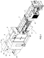
- the drives 21 are housed in a small box 27 mounted on the rear side of the wiredrawing machine 2, next to the motors 8 ( figure 4 ), the drives 22 are housed in the control board 5 and the drives 23 are housed in a further small box 28 mounted on a rear wall 29 of the protection casing 10 at a given height from the ground ( figure 4 ).
- the DC bus 24 partially extends inside the control board 5 and the boxes 27 and 28.
- the position in which the boxes 27 and 28 are installed requires them to have a degree of protection at least of level IP54.
- the power cables (not shown) connecting the drives 21, 22 and 23 to the respective motors 8, 15 and 20 are longer than the ones of the embodiment of figures 1-3 .
- the box 27 is shaped so as not to project from the rear side 12 more than the motors 8 do.
- the base 30 of the spooler 4 normally is deeper, transversely to the wiredrawing direction T, than the upper part of the protection casing 10 where the rear wall 29 is located; the box 28 is shaped so as to remain within the depth of the base 30. Therefore, the imprint of the wiredrawing line 1 on the ground is not influenced by the presence of the boxes 27 and 28.
- the main advantage of the wiredrawing line 1 described above is that of having a definitely smaller imprint on the ground compared to the existing lines with the same production capacity, since the drives of the motors are mounted on board the wiredrawing line and, therefore, there is no need for external boxes resting on the ground and used to hold the drives themselves.
- the wiredrawing line comprises an annealing furnace with the relative control board
- the direct current intermediate-volt voltage generated inside the control board can be used to supply power to the inverters of the drives, by means of a direct current bus running along the wiredrawing line 1.
- the presence of the drives on board the wiredrawing line allows a significant reduction in the length of the cables connecting the drives and the motors, especially in case the drives are directly mounted on the respective motors.
Landscapes
- Engineering & Computer Science (AREA)
- Mechanical Engineering (AREA)
- Spinning Or Twisting Of Yarns (AREA)
- Metal Extraction Processes (AREA)
Claims (10)
- Drahtziehlinie zum Drahtziehen von mindestens einem Metalldraht, Walzdraht oder Band, wobei die Drahtziehlinie (1) umfasst:- eine Vielzahl von Rotationsorganen (6, 13, 14, 19), die während des Arbeitsprozesses der Drahtziehlinie (1) auf den Metalldraht, die Drahtstange oder das Metallband einwirken;- eine Vielzahl von Induktionsmotoren (8, 15, 20), von denen jeder ausgelegt ist, die Rotation eines oder mehrerer der besagten Rotationsorgane (6, 13, 14, 19) zu bewirken;- eine Vielzahl von Antrieben (21-23), von denen jeder ausgelegt ist, jeweils einen der besagten Motoren (8, 15, 20) zu steuern, und mindestens einen Gleichstrom-Wechselrichter umfasst; und- Stromversorgungsmittel (16), die ausgelegt sind, eine Gleichstrom-Zwischenvolt-Spannung (Udc) zu erzeugen, um die besagten Antriebe (21-23) mit Strom zu versorgen;
wobei die Drahtziehlinie (1) dadurch gekennzeichnet ist, dass die besagten Antriebe (21-23) an Bord des jeweiligen Motors (8, 15, 20) montiert sind und dass sie einen einzigen Gleichspannungsbus (24) umfasst, welcher mit dem Ausgang der besagten Stromversorgungsmittel (16) verbunden ist und entlang der Drahtziehlinie (1) montiert ist, um alle Antriebe (21-23) mit der besagten Zwischenspannung zu versorgen. - Drahtziehlinie nach Anspruch 1 und umfassend eine Drahtziehmaschine (2) und einen Glühofen (3), der an den Ausgang der Drahtziehmaschine (2) angeschlossen ist; wobei die besagten Stromversorgungsmittel (16) an Bord des Glühofens (3) montiert sind.
- Drahtziehlinie nach Anspruch 2, wobei der besagte Glühofen (3) ein erstes Schutzgehäuse (9) und eine Steuerplatine (5) aufweist, welche an einer ersten Wand (11) des ersten Schutzgehäuses (9) montiert ist und die besagten Stromversorgungsmittel (16) und, mit deren Ausgang verbunden, Spannungstransformationsmittel (18) umfasst, um eine Gleichstrom-Niedervolt-Spannung (Uann) zu liefern, welche für das Glühen verwendet wird.
- Drahtziehlinie nach Anspruch 3, wobei die besagte Vielzahl von Rotationsorganen (6, 13, 14, 19) mindestens ein zweites Rotationsorgan (14) umfasst, das Teil des besagten Glühofens (3) ist, wobei die besagte Vielzahl von Motoren (8, 15, 20) mindestens einen zweiten Motor (15) umfasst, der mit dem zweiten Rotationsorgan (13, 14) verbunden ist, und die besagten Antriebe (21-23) mindestens einen zweiten Antrieb (22) umfassen, der mit dem zweiten Motor (15) verbunden und in der Steuerplatine (5) untergebracht ist.
- Drahtziehlinie nach einem der Ansprüche 1 bis 4 und umfassend einen Kommunikationsbus (25), welcher entlang der Drahtziehlinie (1) montiert ist, eine Steuerkanzel und Steuermittel (26), welche in der Steuerkanzel untergebracht sind und dazu ausgelegt sind, die besagte Vielzahl von Antrieben (21-23) mittels des besagten Kommunikationsbusses (25) zu steuern.
- Drahtziehlinie nach Anspruch 3 oder 4 und umfassend einen Kommunikationsbus (25), welcher entlang der Drahtziehlinie (1) montiert ist, und Steuermittel (26), welche in der Steuerplatine (5) untergebracht sind und dazu ausgelegt sind, die besagte Vielzahl von Antrieben (21-23) mittels des besagten Kommunikationsbusses (25) zu steuern.
- Drahtziehlinie nach einem der Ansprüche 1 bis 6 und umfassend eine Drahtziehmaschine (2); wobei die besagte Vielzahl von Rotationsorganen (6, 13, 14, 19) erste Ziehorgane (6) umfasst, die Teil der Drahtziehmaschine (2) sind, wobei die besagte Vielzahl von Motoren (8, 15, 20) erste Motoren (8) umfasst, die mit den ersten Rotationsorganen (6) verbunden sind, wobei die besagten Antriebe (21-23) erste Antriebe (21) umfassen, die mit den ersten Motoren (8) verbunden sind; wobei ein Teil jedes der besagten ersten Motoren (8) von einer Rückseite (12) der besagten Drahtziehmaschine (2), die im Wesentlichen parallel zu einer Drahtziehrichtung (T) ist, in einem Ausmaß vorsteht, das so beschaffen ist, dass es den Abdruck der Drahtziehmaschine (2) auf dem Boden nicht verändert.
- Drahtziehlinie nach Anspruch 3 oder 4, wobei der besagte Glühofen (3) mit der besagten Drahtziehmaschine (2) entlang einer Drahtziehrichtung (T) ausgerichtet ist und die besagte erste Wand (11) quer zur Drahtziehrichtung (T) verläuft, so dass die Installation der besagten Steuerplatine (5) den Abdruck der Drahtziehlinie (1) auf dem Boden quer zur Drahtziehrichtung (T) nicht verändert.
- Drahtziehlinie nach Anspruch 1 und umfassend eine Vielzahl von Maschinen (2-4), wobei jedes der besagten Rotationsorgane (6, 13, 14, 19) Teil einer entsprechenden Maschine (2-4) ist und jeder Antrieb (21-23) an Bord einer entsprechenden Maschine (2-4) montiert ist, welche das Rotationsorgan (6, 13, 14, 19) umfasst, das über den entsprechenden Motor (8, 15, 20) mit dem Antrieb (21-23) selbst verbunden ist.
- Drahtziehlinie nach Anspruch 9, wobei die besagte Vielzahl von Maschinen (2-4) eine Drahtziehmaschine (2), einen Glühofen (3), der mit dem Ausgang der Drahtziehmaschine (2) verbunden ist, und einen Spuler (4), der mit dem Ausgang des Glühofens (3) verbunden ist, umfasst.
Applications Claiming Priority (2)
| Application Number | Priority Date | Filing Date | Title |
|---|---|---|---|
| ITBO20140598 | 2014-10-27 | ||
| PCT/IB2015/058281 WO2016067201A1 (en) | 2014-10-27 | 2015-10-27 | Wiredrawing line for wiredrawing a metal wire, wire rod or strap |
Publications (2)
| Publication Number | Publication Date |
|---|---|
| EP3212344A1 EP3212344A1 (de) | 2017-09-06 |
| EP3212344B1 true EP3212344B1 (de) | 2020-12-02 |
Family
ID=51951860
Family Applications (1)
| Application Number | Title | Priority Date | Filing Date |
|---|---|---|---|
| EP15805265.4A Not-in-force EP3212344B1 (de) | 2014-10-27 | 2015-10-27 | Drahtziehanlage zum drahtziehen eines metalldrahtes, eines walzdrahts oder eines streifens |
Country Status (3)
| Country | Link |
|---|---|
| EP (1) | EP3212344B1 (de) |
| CN (1) | CN107206445B (de) |
| WO (1) | WO2016067201A1 (de) |
Families Citing this family (4)
| Publication number | Priority date | Publication date | Assignee | Title |
|---|---|---|---|---|
| CN109967541A (zh) * | 2019-05-05 | 2019-07-05 | 郭永祥 | 一种适用于电缆内部铜丝拉丝的加工装置 |
| CN114632830B (zh) * | 2022-03-04 | 2023-07-25 | 盐城市星凯环保科技股份有限公司 | 一种电热合金材料用自动拉丝纺丝设备 |
| CN116511269B (zh) * | 2023-04-18 | 2023-12-12 | 浙江明铖金属科技股份有限公司 | 一种紧固件拉丝工序用拉丝机及其拉丝工艺 |
| CN120772260B (zh) * | 2025-07-22 | 2026-01-30 | 山西宏达钢铁有限公司 | 一种拉丝钢高效制备自动化设备及制备方法 |
Family Cites Families (9)
| Publication number | Priority date | Publication date | Assignee | Title |
|---|---|---|---|---|
| DE29900994U1 (de) * | 1999-01-21 | 1999-05-06 | Henrich Gmbh, 35745 Herborn | Anlage zur kontinuierlichen Herstellung von mehrdrähtigem Stranggut |
| CN2621846Y (zh) * | 2003-04-09 | 2004-06-30 | 上海金东线缆设备有限公司 | 一种8头为单元的连续退火拉丝机 |
| DE102006017671B4 (de) * | 2006-04-12 | 2015-05-28 | Ernst Koch Gmbh & Co Kg | Drahtziehvorrichtung |
| CN201030483Y (zh) * | 2007-04-12 | 2008-03-05 | 郑州恒杰实业有限公司 | 拉丝、退火、收丝智能联合设备机组 |
| CN102059263A (zh) * | 2010-12-03 | 2011-05-18 | 赵义敏 | 一种拉丝机控制系统 |
| JP5363598B2 (ja) * | 2011-04-07 | 2013-12-11 | ファナック株式会社 | 直流交流変換装置を接続可能なモータ駆動制御装置 |
| CN102489533B (zh) * | 2011-12-04 | 2013-08-14 | 西北有色金属研究院 | 一种MgB2线材的电塑性拉拔装置及拉拔方法 |
| AT512676B1 (de) * | 2012-03-23 | 2021-03-15 | Steinklauber Ind & Vermoegensverwaltung Gmbh | Drahtziehvorrichtung |
| CN203470504U (zh) * | 2013-09-04 | 2014-03-12 | 江阴华电新材料有限公司 | 一种铜线拉丝退火一体机 |
-
2015
- 2015-10-27 EP EP15805265.4A patent/EP3212344B1/de not_active Not-in-force
- 2015-10-27 WO PCT/IB2015/058281 patent/WO2016067201A1/en not_active Ceased
- 2015-10-27 CN CN201580057198.XA patent/CN107206445B/zh not_active Expired - Fee Related
Non-Patent Citations (1)
| Title |
|---|
| None * |
Also Published As
| Publication number | Publication date |
|---|---|
| CN107206445A (zh) | 2017-09-26 |
| EP3212344A1 (de) | 2017-09-06 |
| WO2016067201A1 (en) | 2016-05-06 |
| CN107206445B (zh) | 2019-03-08 |
Similar Documents
| Publication | Publication Date | Title |
|---|---|---|
| EP3212344A1 (de) | Drahtziehanlage zum drahtziehen eines metalldrahtes, eines walzdrahts oder eines streifens | |
| DE102012100248A1 (de) | Elektrische Permanentmagnetmaschine mit integriertem Magnetflussgeber | |
| CN118675819A (zh) | 一种电缆剥皮装置 | |
| EP4708667A1 (de) | Cloud-motor und steuerungsverfahren für cloud-motor | |
| CN104944215A (zh) | 一种自动绕线机 | |
| KR20210151978A (ko) | 스테이터 어셈블리, 모터, 압축기 및 냉방기기 | |
| US20110031840A1 (en) | Electrical Drive Machine | |
| CN202153389U (zh) | 光伏组件用焊带浸锡产线上的收线满盘报警装置 | |
| CN204102640U (zh) | 多功能电缆绞制装置 | |
| CN211569744U (zh) | 一种钢帘线收线机恒张力控制装置 | |
| ITBO20140098U1 (it) | Linea di trafilatura per la trafilatura di un filo, vergella o piattina di metallo | |
| CN103051129A (zh) | 一种单相异步电动机 | |
| CN206164251U (zh) | 电机绝缘支架、定子及电机 | |
| EP3007325A1 (de) | Hybrider leiter für generatorstatorwicklung | |
| CN112072889B (zh) | 永磁直线电机、其永磁体磁性能在线检测装置及方法 | |
| CN104269233B (zh) | 带驱鸟器的绝缘子 | |
| CN204167835U (zh) | 节能型共箱母线装置 | |
| CN221282737U (zh) | 新型电线电缆剥皮机 | |
| CN210778029U (zh) | 一种电缆用铜线张弛度调节设备 | |
| CN220334366U (zh) | 一种电缆收线装置 | |
| CN203582202U (zh) | 一种自动绕线机 | |
| CN220702850U (zh) | 一种自动导线机 | |
| CN216564317U (zh) | 一种新型多功能的电缆剥皮机 | |
| CN215299753U (zh) | 一种线束生产一体化装置 | |
| CN213691601U (zh) | 一种高压电缆生产用高精度编织机 |
Legal Events
| Date | Code | Title | Description |
|---|---|---|---|
| STAA | Information on the status of an ep patent application or granted ep patent |
Free format text: STATUS: THE INTERNATIONAL PUBLICATION HAS BEEN MADE |
|
| PUAI | Public reference made under article 153(3) epc to a published international application that has entered the european phase |
Free format text: ORIGINAL CODE: 0009012 |
|
| STAA | Information on the status of an ep patent application or granted ep patent |
Free format text: STATUS: REQUEST FOR EXAMINATION WAS MADE |
|
| 17P | Request for examination filed |
Effective date: 20170424 |
|
| AK | Designated contracting states |
Kind code of ref document: A1 Designated state(s): AL AT BE BG CH CY CZ DE DK EE ES FI FR GB GR HR HU IE IS IT LI LT LU LV MC MK MT NL NO PL PT RO RS SE SI SK SM TR |
|
| AX | Request for extension of the european patent |
Extension state: BA ME |
|
| DAV | Request for validation of the european patent (deleted) | ||
| DAX | Request for extension of the european patent (deleted) | ||
| STAA | Information on the status of an ep patent application or granted ep patent |
Free format text: STATUS: EXAMINATION IS IN PROGRESS |
|
| 17Q | First examination report despatched |
Effective date: 20190524 |
|
| GRAP | Despatch of communication of intention to grant a patent |
Free format text: ORIGINAL CODE: EPIDOSNIGR1 |
|
| STAA | Information on the status of an ep patent application or granted ep patent |
Free format text: STATUS: GRANT OF PATENT IS INTENDED |
|
| INTG | Intention to grant announced |
Effective date: 20200526 |
|
| GRAS | Grant fee paid |
Free format text: ORIGINAL CODE: EPIDOSNIGR3 |
|
| GRAJ | Information related to disapproval of communication of intention to grant by the applicant or resumption of examination proceedings by the epo deleted |
Free format text: ORIGINAL CODE: EPIDOSDIGR1 |
|
| GRAL | Information related to payment of fee for publishing/printing deleted |
Free format text: ORIGINAL CODE: EPIDOSDIGR3 |
|
| STAA | Information on the status of an ep patent application or granted ep patent |
Free format text: STATUS: EXAMINATION IS IN PROGRESS |
|
| GRAR | Information related to intention to grant a patent recorded |
Free format text: ORIGINAL CODE: EPIDOSNIGR71 |
|
| STAA | Information on the status of an ep patent application or granted ep patent |
Free format text: STATUS: GRANT OF PATENT IS INTENDED |
|
| INTC | Intention to grant announced (deleted) | ||
| GRAA | (expected) grant |
Free format text: ORIGINAL CODE: 0009210 |
|
| STAA | Information on the status of an ep patent application or granted ep patent |
Free format text: STATUS: THE PATENT HAS BEEN GRANTED |
|
| INTG | Intention to grant announced |
Effective date: 20201013 |
|
| AK | Designated contracting states |
Kind code of ref document: B1 Designated state(s): AL AT BE BG CH CY CZ DE DK EE ES FI FR GB GR HR HU IE IS IT LI LT LU LV MC MK MT NL NO PL PT RO RS SE SI SK SM TR |
|
| REG | Reference to a national code |
Ref country code: GB Ref legal event code: FG4D |
|
| REG | Reference to a national code |
Ref country code: AT Ref legal event code: REF Ref document number: 1340334 Country of ref document: AT Kind code of ref document: T Effective date: 20201215 Ref country code: CH Ref legal event code: EP |
|
| REG | Reference to a national code |
Ref country code: DE Ref legal event code: R096 Ref document number: 602015062984 Country of ref document: DE |
|
| REG | Reference to a national code |
Ref country code: IE Ref legal event code: FG4D |
|
| PG25 | Lapsed in a contracting state [announced via postgrant information from national office to epo] |
Ref country code: NO Free format text: LAPSE BECAUSE OF FAILURE TO SUBMIT A TRANSLATION OF THE DESCRIPTION OR TO PAY THE FEE WITHIN THE PRESCRIBED TIME-LIMIT Effective date: 20210302 Ref country code: FI Free format text: LAPSE BECAUSE OF FAILURE TO SUBMIT A TRANSLATION OF THE DESCRIPTION OR TO PAY THE FEE WITHIN THE PRESCRIBED TIME-LIMIT Effective date: 20201202 Ref country code: RS Free format text: LAPSE BECAUSE OF FAILURE TO SUBMIT A TRANSLATION OF THE DESCRIPTION OR TO PAY THE FEE WITHIN THE PRESCRIBED TIME-LIMIT Effective date: 20201202 Ref country code: GR Free format text: LAPSE BECAUSE OF FAILURE TO SUBMIT A TRANSLATION OF THE DESCRIPTION OR TO PAY THE FEE WITHIN THE PRESCRIBED TIME-LIMIT Effective date: 20210303 |
|
| REG | Reference to a national code |
Ref country code: NL Ref legal event code: MP Effective date: 20201202 |
|
| REG | Reference to a national code |
Ref country code: AT Ref legal event code: MK05 Ref document number: 1340334 Country of ref document: AT Kind code of ref document: T Effective date: 20201202 |
|
| PG25 | Lapsed in a contracting state [announced via postgrant information from national office to epo] |
Ref country code: SE Free format text: LAPSE BECAUSE OF FAILURE TO SUBMIT A TRANSLATION OF THE DESCRIPTION OR TO PAY THE FEE WITHIN THE PRESCRIBED TIME-LIMIT Effective date: 20201202 Ref country code: LV Free format text: LAPSE BECAUSE OF FAILURE TO SUBMIT A TRANSLATION OF THE DESCRIPTION OR TO PAY THE FEE WITHIN THE PRESCRIBED TIME-LIMIT Effective date: 20201202 Ref country code: PL Free format text: LAPSE BECAUSE OF FAILURE TO SUBMIT A TRANSLATION OF THE DESCRIPTION OR TO PAY THE FEE WITHIN THE PRESCRIBED TIME-LIMIT Effective date: 20201202 Ref country code: BG Free format text: LAPSE BECAUSE OF FAILURE TO SUBMIT A TRANSLATION OF THE DESCRIPTION OR TO PAY THE FEE WITHIN THE PRESCRIBED TIME-LIMIT Effective date: 20210302 |
|
| PG25 | Lapsed in a contracting state [announced via postgrant information from national office to epo] |
Ref country code: NL Free format text: LAPSE BECAUSE OF FAILURE TO SUBMIT A TRANSLATION OF THE DESCRIPTION OR TO PAY THE FEE WITHIN THE PRESCRIBED TIME-LIMIT Effective date: 20201202 Ref country code: HR Free format text: LAPSE BECAUSE OF FAILURE TO SUBMIT A TRANSLATION OF THE DESCRIPTION OR TO PAY THE FEE WITHIN THE PRESCRIBED TIME-LIMIT Effective date: 20201202 |
|
| REG | Reference to a national code |
Ref country code: LT Ref legal event code: MG9D |
|
| PG25 | Lapsed in a contracting state [announced via postgrant information from national office to epo] |
Ref country code: PT Free format text: LAPSE BECAUSE OF FAILURE TO SUBMIT A TRANSLATION OF THE DESCRIPTION OR TO PAY THE FEE WITHIN THE PRESCRIBED TIME-LIMIT Effective date: 20210405 Ref country code: SK Free format text: LAPSE BECAUSE OF FAILURE TO SUBMIT A TRANSLATION OF THE DESCRIPTION OR TO PAY THE FEE WITHIN THE PRESCRIBED TIME-LIMIT Effective date: 20201202 Ref country code: RO Free format text: LAPSE BECAUSE OF FAILURE TO SUBMIT A TRANSLATION OF THE DESCRIPTION OR TO PAY THE FEE WITHIN THE PRESCRIBED TIME-LIMIT Effective date: 20201202 Ref country code: LT Free format text: LAPSE BECAUSE OF FAILURE TO SUBMIT A TRANSLATION OF THE DESCRIPTION OR TO PAY THE FEE WITHIN THE PRESCRIBED TIME-LIMIT Effective date: 20201202 Ref country code: SM Free format text: LAPSE BECAUSE OF FAILURE TO SUBMIT A TRANSLATION OF THE DESCRIPTION OR TO PAY THE FEE WITHIN THE PRESCRIBED TIME-LIMIT Effective date: 20201202 Ref country code: CZ Free format text: LAPSE BECAUSE OF FAILURE TO SUBMIT A TRANSLATION OF THE DESCRIPTION OR TO PAY THE FEE WITHIN THE PRESCRIBED TIME-LIMIT Effective date: 20201202 Ref country code: EE Free format text: LAPSE BECAUSE OF FAILURE TO SUBMIT A TRANSLATION OF THE DESCRIPTION OR TO PAY THE FEE WITHIN THE PRESCRIBED TIME-LIMIT Effective date: 20201202 |
|
| PG25 | Lapsed in a contracting state [announced via postgrant information from national office to epo] |
Ref country code: AT Free format text: LAPSE BECAUSE OF FAILURE TO SUBMIT A TRANSLATION OF THE DESCRIPTION OR TO PAY THE FEE WITHIN THE PRESCRIBED TIME-LIMIT Effective date: 20201202 |
|
| REG | Reference to a national code |
Ref country code: DE Ref legal event code: R097 Ref document number: 602015062984 Country of ref document: DE |
|
| PG25 | Lapsed in a contracting state [announced via postgrant information from national office to epo] |
Ref country code: IS Free format text: LAPSE BECAUSE OF FAILURE TO SUBMIT A TRANSLATION OF THE DESCRIPTION OR TO PAY THE FEE WITHIN THE PRESCRIBED TIME-LIMIT Effective date: 20210402 |
|
| PLBE | No opposition filed within time limit |
Free format text: ORIGINAL CODE: 0009261 |
|
| STAA | Information on the status of an ep patent application or granted ep patent |
Free format text: STATUS: NO OPPOSITION FILED WITHIN TIME LIMIT |
|
| PG25 | Lapsed in a contracting state [announced via postgrant information from national office to epo] |
Ref country code: AL Free format text: LAPSE BECAUSE OF FAILURE TO SUBMIT A TRANSLATION OF THE DESCRIPTION OR TO PAY THE FEE WITHIN THE PRESCRIBED TIME-LIMIT Effective date: 20201202 |
|
| 26N | No opposition filed |
Effective date: 20210903 |
|
| PG25 | Lapsed in a contracting state [announced via postgrant information from national office to epo] |
Ref country code: DK Free format text: LAPSE BECAUSE OF FAILURE TO SUBMIT A TRANSLATION OF THE DESCRIPTION OR TO PAY THE FEE WITHIN THE PRESCRIBED TIME-LIMIT Effective date: 20201202 Ref country code: SI Free format text: LAPSE BECAUSE OF FAILURE TO SUBMIT A TRANSLATION OF THE DESCRIPTION OR TO PAY THE FEE WITHIN THE PRESCRIBED TIME-LIMIT Effective date: 20201202 |
|
| PG25 | Lapsed in a contracting state [announced via postgrant information from national office to epo] |
Ref country code: ES Free format text: LAPSE BECAUSE OF FAILURE TO SUBMIT A TRANSLATION OF THE DESCRIPTION OR TO PAY THE FEE WITHIN THE PRESCRIBED TIME-LIMIT Effective date: 20201202 |
|
| PGFP | Annual fee paid to national office [announced via postgrant information from national office to epo] |
Ref country code: DE Payment date: 20211101 Year of fee payment: 7 |
|
| REG | Reference to a national code |
Ref country code: CH Ref legal event code: PL |
|
| PG25 | Lapsed in a contracting state [announced via postgrant information from national office to epo] |
Ref country code: IS Free format text: LAPSE BECAUSE OF FAILURE TO SUBMIT A TRANSLATION OF THE DESCRIPTION OR TO PAY THE FEE WITHIN THE PRESCRIBED TIME-LIMIT Effective date: 20210402 |
|
| REG | Reference to a national code |
Ref country code: BE Ref legal event code: MM Effective date: 20211031 |
|
| GBPC | Gb: european patent ceased through non-payment of renewal fee |
Effective date: 20211027 |
|
| PG25 | Lapsed in a contracting state [announced via postgrant information from national office to epo] |
Ref country code: MC Free format text: LAPSE BECAUSE OF FAILURE TO SUBMIT A TRANSLATION OF THE DESCRIPTION OR TO PAY THE FEE WITHIN THE PRESCRIBED TIME-LIMIT Effective date: 20201202 |
|
| PG25 | Lapsed in a contracting state [announced via postgrant information from national office to epo] |
Ref country code: LU Free format text: LAPSE BECAUSE OF NON-PAYMENT OF DUE FEES Effective date: 20211027 Ref country code: GB Free format text: LAPSE BECAUSE OF NON-PAYMENT OF DUE FEES Effective date: 20211027 Ref country code: BE Free format text: LAPSE BECAUSE OF NON-PAYMENT OF DUE FEES Effective date: 20211031 |
|
| PG25 | Lapsed in a contracting state [announced via postgrant information from national office to epo] |
Ref country code: LI Free format text: LAPSE BECAUSE OF NON-PAYMENT OF DUE FEES Effective date: 20211031 Ref country code: CH Free format text: LAPSE BECAUSE OF NON-PAYMENT OF DUE FEES Effective date: 20211031 |
|
| PG25 | Lapsed in a contracting state [announced via postgrant information from national office to epo] |
Ref country code: FR Free format text: LAPSE BECAUSE OF NON-PAYMENT OF DUE FEES Effective date: 20211031 |
|
| PG25 | Lapsed in a contracting state [announced via postgrant information from national office to epo] |
Ref country code: IE Free format text: LAPSE BECAUSE OF NON-PAYMENT OF DUE FEES Effective date: 20211027 |
|
| REG | Reference to a national code |
Ref country code: DE Ref legal event code: R119 Ref document number: 602015062984 Country of ref document: DE |
|
| PG25 | Lapsed in a contracting state [announced via postgrant information from national office to epo] |
Ref country code: HU Free format text: LAPSE BECAUSE OF FAILURE TO SUBMIT A TRANSLATION OF THE DESCRIPTION OR TO PAY THE FEE WITHIN THE PRESCRIBED TIME-LIMIT; INVALID AB INITIO Effective date: 20151027 |
|
| PG25 | Lapsed in a contracting state [announced via postgrant information from national office to epo] |
Ref country code: IT Free format text: LAPSE BECAUSE OF NON-PAYMENT OF DUE FEES Effective date: 20211031 Ref country code: CY Free format text: LAPSE BECAUSE OF FAILURE TO SUBMIT A TRANSLATION OF THE DESCRIPTION OR TO PAY THE FEE WITHIN THE PRESCRIBED TIME-LIMIT Effective date: 20201202 |
|
| PG25 | Lapsed in a contracting state [announced via postgrant information from national office to epo] |
Ref country code: DE Free format text: LAPSE BECAUSE OF NON-PAYMENT OF DUE FEES Effective date: 20230503 |
|
| PG25 | Lapsed in a contracting state [announced via postgrant information from national office to epo] |
Ref country code: MK Free format text: LAPSE BECAUSE OF FAILURE TO SUBMIT A TRANSLATION OF THE DESCRIPTION OR TO PAY THE FEE WITHIN THE PRESCRIBED TIME-LIMIT Effective date: 20201202 |
|
| PG25 | Lapsed in a contracting state [announced via postgrant information from national office to epo] |
Ref country code: TR Free format text: LAPSE BECAUSE OF FAILURE TO SUBMIT A TRANSLATION OF THE DESCRIPTION OR TO PAY THE FEE WITHIN THE PRESCRIBED TIME-LIMIT Effective date: 20201202 |
|
| PG25 | Lapsed in a contracting state [announced via postgrant information from national office to epo] |
Ref country code: MT Free format text: LAPSE BECAUSE OF FAILURE TO SUBMIT A TRANSLATION OF THE DESCRIPTION OR TO PAY THE FEE WITHIN THE PRESCRIBED TIME-LIMIT Effective date: 20201202 |