EP3212831B1 - Rundstrickmaschine für maschenwaren und dergleichen mit platinenbetätigungsvorrichtung - Google Patents
Rundstrickmaschine für maschenwaren und dergleichen mit platinenbetätigungsvorrichtung Download PDFInfo
- Publication number
- EP3212831B1 EP3212831B1 EP15794095.8A EP15794095A EP3212831B1 EP 3212831 B1 EP3212831 B1 EP 3212831B1 EP 15794095 A EP15794095 A EP 15794095A EP 3212831 B1 EP3212831 B1 EP 3212831B1
- Authority
- EP
- European Patent Office
- Prior art keywords
- needle cylinder
- axis
- cam
- pusher
- respect
- Prior art date
- Legal status (The legal status is an assumption and is not a legal conclusion. Google has not performed a legal analysis and makes no representation as to the accuracy of the status listed.)
- Active
Links
Images




Classifications
-
- D—TEXTILES; PAPER
- D04—BRAIDING; LACE-MAKING; KNITTING; TRIMMINGS; NON-WOVEN FABRICS
- D04B—KNITTING
- D04B15/00—Details of, or auxiliary devices incorporated in, weft knitting machines, restricted to machines of this kind
- D04B15/32—Cam systems or assemblies for operating knitting instruments
- D04B15/34—Cam systems or assemblies for operating knitting instruments for dials
-
- D—TEXTILES; PAPER
- D04—BRAIDING; LACE-MAKING; KNITTING; TRIMMINGS; NON-WOVEN FABRICS
- D04B—KNITTING
- D04B9/00—Circular knitting machines with independently-movable needles
- D04B9/20—Circular knitting machines with independently-movable needles with provision for narrowing or widening; with reciprocatory action, e.g. for knitting of flat portions
-
- D—TEXTILES; PAPER
- D04—BRAIDING; LACE-MAKING; KNITTING; TRIMMINGS; NON-WOVEN FABRICS
- D04B—KNITTING
- D04B15/00—Details of, or auxiliary devices incorporated in, weft knitting machines, restricted to machines of this kind
- D04B15/06—Sinkers
-
- D—TEXTILES; PAPER
- D04—BRAIDING; LACE-MAKING; KNITTING; TRIMMINGS; NON-WOVEN FABRICS
- D04B—KNITTING
- D04B15/00—Details of, or auxiliary devices incorporated in, weft knitting machines, restricted to machines of this kind
- D04B15/32—Cam systems or assemblies for operating knitting instruments
-
- D—TEXTILES; PAPER
- D04—BRAIDING; LACE-MAKING; KNITTING; TRIMMINGS; NON-WOVEN FABRICS
- D04B—KNITTING
- D04B15/00—Details of, or auxiliary devices incorporated in, weft knitting machines, restricted to machines of this kind
- D04B15/94—Driving-gear not otherwise provided for
Definitions
- the present invention relates to a circular machine for knitting, hosiery or the like, with sinker actuation device.
- circular machines for knitting or hosiery comprise a needle cylinder with a vertical axis, on the lateral surface of which there is a plurality of axial grooves, each of which accommodates, so that it can slide parallel to the axis of the needle cylinder, a corresponding needle.
- the needles can be actuated with a reciprocating motion along the corresponding axial groove so as to pick up at least one yarn dispensed at a feed or drop of the machine and form loops of knitting.
- the yarns to be used to manufacture the knitting are dispensed by adapted yarn fingers arranged at the so-called feeds or drops of the machine. Such yarn fingers are usually movable on command in order to place their yarn dispensing end in a position that is suitable to allow the needles to pick up the yarn or to a position that prevents the needles from picking up the yarn.
- the needles are provided with heels that protrude from the lateral surface of the needle cylinder and engage paths defined by needle actuation cams that face the lateral surface of the needle cylinder.
- Such paths have rising portions and descending portions so that the heels of the needles, following the paths as a consequence of the rotation of the needle cylinder about its own axis with respect to the needle actuation cams, are pushed so as to protrude with their head or tip upwardly from the needle cylinder in order to pick up at least one yarn that is dispensed at a feed or drop and then descend to form new loops of knitting with the yarn that they have picked up.
- Such machines are usually provided with sinkers that are arranged within radial grooves of an adapted support, known as "sinker ring", which is associated integrally with the needle cylinder at its upper end.
- the sinkers are offset with respect to the needles so that each sinker lies between two contiguous needles and are actuated, during the rotation of the needle cylinder about its own axis, with a reciprocating motion along a radial direction with respect to the needle cylinder.
- the sinkers are moved away from the axis of the needle cylinder when the needles, after picking up the yarn at a feed or drop, begin their descent in order to form new loops of knitting, so that the region of the yarn or yarns comprised between two contiguous loops of knitting rests on the upper portion or "nose" of the sinkers, which is usually flat and is known as "knockover plane", while the previously formed loops are knocked over, i.e., abandoned by the corresponding needle or retained within the head or tip of the needle together with the new formed loops of knitting, depending on the type of knitting to be provided.
- the sinkers are moved toward the axis of the needle cylinder so as to engage the old loops of knitting by means of a hook that lies above the knockover plane, so as to obtain a tensioning of the loops of knitting against the shank of the needles.
- This tensioning against the shank of the needles also obtains the effect of causing assuredly the opening of the latch of the needles.
- the movement of the sinkers along a radial direction with respect to the needle cylinder is obtained by means of corresponding actuation cams that are supported by a sinker cap, which has an annular shape and is arranged above and coaxially with respect to the sinker ring.
- the sinker actuation cams define at least one path that is extended around the axis of the needle cylinder, with portions that progressively approach the axis of the needle cylinder and portions that are spaced progressively further away from the axis of the needle cylinder. Heels of the sinkers that protrude upwardly from the sinker ring engage in these paths.
- the sinkers when the needle cylinder is actuated with a rotary motion about its own axis with respect to the sinker cap, the sinkers, by following the paths defined by the corresponding actuation cams supported by the sinker cap, are moved alternatively toward and away from the axis of the needle cylinder in a manner that is coordinated with the reciprocating motion of the needles along the axial grooves of the needle cylinder so as to cooperate with them in forming the knitting, as described above.
- the needle cylinder is actuated with an alternating rotary motion about its own axis and only some of the needles arranged in the needle cylinder are moved to knit at a feed or drop of the machine.
- two pusher cams respectively a first pusher cam and a second pusher cam
- the function of the pusher cams is to move the sinkers, located between the needles that picked up the yarn or yarns at the feed being considered and formed new loops of knitting, toward the axis of the needle cylinder, during the rotary motion in one direction of the needle cylinder, when the needles begin a new upward motion in preparation for pickup of the yarn at the feed being considered, which will be performed during the rotary motion of the needle cylinder in the opposite direction.
- Such machines are known, for example, from US999853A and GB13092A .
- the pusher cams are fixed and apply equally a pushing action both on the sinkers located between the needles that are knitting and on the sinkers located between the needles that are excluded from knitting, i.e., are not moved to knit at the feed being considered.
- the needles that are excluded from knitting are kept with their head or tip between the sinkers below the knockover plane, tensioning the loops of knitting formed previously and retained within their head.
- the pushing action on the sinkers has the effect of increasing further the tension of the loops of knitting formed previously, which rest on the knockover plane of the sinkers.
- pusher cams which can move individually in a radial direction with respect to the axis of the needle cylinder by means of pneumatic actuators mounted on the sinker cap.
- Such actuators in addition to increasing the complexity of the provision and installation of the sinker cap, suffer the drawback of low reliability, since the operation of the actuators is conditioned heavily by the temperature and by other external factors.
- the aim of the present invention is to solve the problem described above, by providing a circular machine for knitting, hosiery or the like with a sinker actuation device that allows to limit the degree of tension applied by the sinkers to the loops of knitting formed previously and arranged on the needles that are excluded from knitting at the feed being used and is highly reliable in operation.
- an object of the invention is to solve the problem described above, without increasing excessively the complexity of the sinker cap and of the elements intended for its actuation.
- Another object of the invention is to provide a machine with a sinker actuation device that ensures high precision and repetitiveness of operation.
- a further object of the invention is to provide a machine with a sinker actuation device that can be manufactured at competitive costs.
- the machine comprises, in per se known manner, a needle cylinder 2, which is arranged so that its axis 2a is substantially vertical and can be actuated with a rotary motion about the axis 2a in both directions of rotation.
- a needle cylinder 2 On the lateral surface of the needle cylinder 2 there are multiple axial grooves 3, each of which accommodates a corresponding needle 4, which is provided with at least one heel 4a that protrudes from the lateral surface of the needle cylinder 2 and can engage paths that are defined by needle actuation cams 41, which are of a known type and are shown only partially in Figures 1 to 4 , arranged around the needle cylinder 2 and facing the lateral surface the needle cylinder 2, which can be actuated with a rotary motion about its own axis 2a with respect to the cams, so that the needles 4, by following these paths with their heel 4a, are actuated with an alternating motion along the corresponding axial groove 3 in order to pick up the yarn or yarns dispensed at at least one feed or
- a sinker ring 6 which is arranged coaxially to the needle cylinder 2 and is integral therewith in rotation about its own axis 2a.
- the sinker ring 6 is composed of an external part 6a, arranged around the needle cylinder 2 at its upper end, and an internal part 6b, which is fixed to the internal side of the upper end of the needle cylinder 2.
- the sinker ring 6 there are multiple grooves 7 that are oriented radially with respect to the needle cylinder 2 and are offset with respect to the axial grooves 3 of the needle cylinder 2, so that each radial groove 7 of the sinker ring 6 lies between two contiguous axial grooves 3 of the needle cylinder 2.
- Each one of the radial grooves 7 accommodates a corresponding sinker 8, which can move along the corresponding radial groove 7 toward and away with respect to the axis 2a of the needle cylinder 2.
- sinker cap 9 which has an annular shape and is arranged coaxially to the sinker ring 6 and therefore coaxially to the needle cylinder 2 and supports sinker actuation cams 10.
- the sinker actuation cams 10 define at least one path that is extended around the axis 2a of the needle cylinder 2 and can be engaged by a heel 8a of the sinkers 8 that protrudes upwardly from the sinker ring 6.
- the path defined by the sinker actuation cams 10 is shaped so as to produce, as a consequence of the rotation of the sinker ring 6 integrally with the needle cylinder 2 with respect to the sinker cap 9, to the sinker actuation cams 10 and to the feed or drop 5, the alternating movement of the sinkers 8 toward and away from the axis 2a of the needle cylinder 2 in order to cooperate with the needles 4 in forming the knitting.
- each sinker 8 there is a sub-sinker 11, which rests on the bottom of the corresponding radial groove 7.
- the sub-sinker 11, of a known type is used to perform, together with other elements that are of a known type and are not shown for the sake of simplicity, a selection of the sinkers 8. It should be noted that the sub-sinker 11 can also be absent. In this case the sinkers 8 rest directly on the bottom of the corresponding radial groove 7.
- the sinker actuation cams 10 comprise two pusher cams, respectively a first pusher cam 12 and a second pusher cam 13, which are arranged on mutually opposite sides with respect to an imaginary plane that passes through the axis 2a of the needle cylinder 2 and through a feed or drop 5 of the machine.
- the pusher cams 12, 13 can engage the heel 8a of the sinkers 8 in order to produce the movement of the sinkers 8 toward the axis 2a of the needle cylinder 2.
- the feed or drop 5 is identified by a thicker line.
- the feed 5 there are one or more yarn fingers 14, which can be actuated in a per se known manner in order to supply the needles 4 moved to knit at the feed 5 one or more yarns to form knitting.
- the first pusher cam 12 and the second pusher cam 13 can move with respect to the sinker cap 9 toward or away from the axis 2a of the needle cylinder 2.
- the machine according to the invention comprises actuation means 15, which act on the first pusher cam 12 and on the second pusher cam 13 in order to move alternatively the first pusher cam 12 or the second pusher cam 13 toward the axis 2a of the needle cylinder 2 or away from the axis 2a of the needle cylinder 2.
- the first pusher cam 12 and the second pusher cam 13 can move on command with respect to the sinker cap 9 from an inactive position, in which they are arranged at a preset distance from the axis 2a of the needle cylinder, to a pusher position, in which they are arranged at a shorter distance from the axis 2a of the needle cylinder 2 with respect to the inactive position.
- the sinker cap 9 comprises an annular cam supporting plate 16 that supports the first pusher cam 12 and the second pusher cam 13 slidingly along a direction that has a radial component with respect to the axis 2a of the needle cylinder 2.
- the actuation means 15 comprise an actuation element 17, which acts alternatively on the first pusher cam 12 and on the second pusher cam 13 in order to produce their movement from the inactive position to the pusher position or vice versa.
- the pusher cams 12, 13 are arranged below the annular cam supporting plate 16 and are fixed to pins 20 that pass through radial slots 18 defined in the annular cam supporting plate 16.
- the radial slots 18 are elongated along directions that have a radial component with respect to the axis 2a of the needle cylinder 2 so as to allow the movement of the corresponding pusher cam 12 or 13 along a radial direction with respect to the needle cylinder 2.
- the actuation element 17 is arranged above the annular cam supporting plate 16 and is extended around the axis 2a of the needle center 2.
- the actuation element 17 has contoured slots 19, which are provided with at least one first portion 19a that is extended substantially concentrically to the axis 2a of the needle cylinder 2 and with at least one second portion 19b that is extended progressively toward the axis 2a of the needle cylinder 2 starting from the first portion 19a.
- the contoured slots 19 are each engaged by one of the pins 20 that are integral with the pusher cams 12, 13 and the actuation element 17 can rotate on command with respect to the annular cam supporting plate 16 about the axis 2a of the needle cylinder 2 from a first position, in which the pins 20 of the first pusher cam 12 are arranged along the first portion 19a of the contoured slots 19 while the pins 20 of the second pusher cam 13 are arranged along the second portion 19b of the contoured slots 19, to a second position, in which the pins 20 of the first pusher cam 12 are arranged along the second portion 19b of the contoured slots 19, while the pins 20 of the second pusher cam 13 are arranged along the first portion 19a of the contoured slots 19.
- the actuation element 17 can be arranged in an intermediate position, between the first position and the second position, in which the pins 20 of the pusher cams 12, 13 are arranged in the passage region between the first portion 19a and the second portion 19b of the contoured slots 19. In this manner, with the actuation element 17 in this intermediate position, it is possible to have both pusher cams 12, 13 in the inactive position.
- each pusher cam 12, 13 is fixed to two pins 20, each of which engages a corresponding contoured slot 19. There are therefore two contoured slots 19 for each pusher cam 12, 13, but the number of contoured slots 19 for each pusher cam 12, 13 can vary according to the requirements.
- the actuation element 17, which is substantially plate-like, has a contoured annular shape that is extended around the axis 2a of the needle cylinder 2.
- the actuation element 17 is supported, so that it can rotate about the axis 2a of the needle cylinder 2, by the annular cam supporting plate 16.
- the actuation means 15 comprise a first electric motor 22, preferably a step motor, which is connected kinematically with its output shaft to a toothed arch 23, which is concentric to the axis 2a of the needle cylinder 2 and is defined in a peripheral region of the actuation element 17.
- the first electric motor 22 can be actuated to produce the rotation of the actuation element 17 about the axis 2a of the needle cylinder 2 with respect to the annular cam supporting plate 16 from the first cited position to the second cited position or to the intermediate position and vice versa, as will become better apparent hereinafter.
- the first electric motor 22 is fixed by means of its body to the annular cam supporting plate 16.
- a toothed pulley 24 is keyed on its output shaft and is connected, by means of a toothed belt 25, to another toothed pulley 26, which is keyed on a transmission shaft 27.
- a gear 28 is keyed on the transmission shaft 27 and meshes with an intermediate gear 29, which in turn mates with the toothed arch 23 of the actuation element 17.
- the output shaft of the first electric motor 22 and the transmission shaft 27, as well as the intermediate gear 29, are arranged so that their axes are parallel to the axis 2a of the needle cylinder 2.
- the intermediate gear 29 is supported, so that it can rotate about its own axis, by a centering wheel 30, which is fixed, by means of screws 31, to the upper face of the annular cam supporting plate 16.
- the extent of the rotation of the actuation element 17 about the axis 2a of the needle cylinder with respect to the annular cam supporting plate 16 can be visualized by providing a graduated sector 32 on the actuation element 17 and a locator 33 on a portion of the annular cam supporting plate 16 or on an element that is integral therewith.
- the annular cam supporting plate 16 instead of being fixed to the supporting structure of the machine, might be supported, so that it can rotate about the axis 2a of the needle cylinder 2, by a supporting element 34, which is integral with the supporting structure of the machine.
- the annular cam supporting plate 16 can be rotated on command about the axis 2a of the needle cylinder 2 with respect to the supporting element 34, by means of the actuation of a second electric motor 35, for example a step motor, through angles of preset breadth in order to anticipate or delay the intervention of the sinker actuation cams 10 on the heels 8a of the sinkers 8.
- the second electric motor 35 can be associated by means of its body with the annular cam supporting plate 16 and can be connected kinematically, by way of its output shaft, to a toothed arch 36, which is concentric to the axis 2a of the needle cylinder 2, defined in a peripheral region of the supporting element 34.
- a gear 37 is keyed on the output shaft of the second electric motor 35 and mates with the toothed arch 36. In this manner, the actuation of the second electric motor 35 produces the rotation of the annular cam supporting plate 16 and of the second electric motor 35 about the axis 2a of the needle cylinder 2 with respect to the supporting element 34.
- centering wheel 30 is covered partially by a protective cover 38 and the contoured slots 19 also are covered by protective plates 39 that are arranged above the actuation element 17 and are retained by the pins 20, provided as screws.
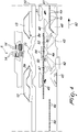
- Figures 1 to 4 show schematically the flat extension of the needle actuation cams 41 and of the sinker actuation cams 10 proximate to a feed or drop 5 of the machine that is used to form knitting when the needle cylinder 2 is actuated with an alternating rotary motion about its own axis 2a.
- a knitting forming cam or knockover cam 42 for the rotary motion of the needle cylinder 2 in the direction of rotation indicated by the arrow 61 in Figures 1 and 2
- a knitting forming cam or knockover cam 43 for the rotary motion of the needle cylinder 2 in the direction of rotation indicated by the arrow 62 in Figures 3 and 4 .
- a central cam 44 is arranged between the knitting forming cams 42, 43.
- Two needle lifting cams 45, 46 are also shown, respectively a first cam for lifting the needles to the tuck or dropped position 45 for the rotary motion of the needle cylinder 2 in the direction of rotation indicated by the arrow 61 in Figures 1 and 2 and a second cam for lifting the needles to the tuck or dropped position 46 for the rotary motion of the needle cylinder 2 in the direction of rotation indicated by the arrow 62 in Figures 3 and 4 .
- the first cam for lifting the needles to the tuck or dropped position 45 and the second cam for lifting the needles to the tuck or dropped position 46 are located on mutually opposite sides with respect to an imaginary plane that passes through the axis 2a of the needle cylinder 2 and through the at least one feed or drop 5 of the machine.
- tie position is understood to reference a position in which the needle 4 is raised to such a level that the loop of knitting formed previously opens the latch of the needle 4 without passing, below it, onto the shank of the needle 4. Should the needle 4 pick up a yarn in this position and form a new loop of knitting, the new loop of knitting would be located in the head of the needle 4 together with the previously formed loop of knitting, providing a stitch known as "tuck stitch”.
- the expression "dropped position” is understood to reference a position in which the needle 4 is raised to such a level that the previously formed loop of knitting opens the latch of the needle 4, passing below it onto the shank of the needle 4. Should the needle 4 pick up a yarn in this position and form a new loop of knitting, the new loop of knitting would be knitted in with the previous loop of knitting, which would be dropped by the needle 4.
- Each one of the cams for lifting the needles to the tuck or dropped position 45, 46 has, at its top, a cam portion 45a, 46a that can move on command, in a per se known manner, along a radial direction with respect to the needle cylinder 2 in order to pass from an active position, in which it is close to the needle cylinder 2 in order to interfere with the heel 4a of the needles 4, to an inactive position, in which it is spaced from the needle cylinder 2 so as to not interfere with the heel 4a of the needles 4.
- cam portion 45a or 46a is in the active position, shown in Figures 1 to 4 , the needles 4 that engage with their heel 4a the lifting cams 45, 46 are raised into the dropped position, while if the cam portion 45a or 46a is in the inactive position, the needles 4 that engage with their heel 4a the lifting cams 45, 46 are raised to the tuck position.
- the first pusher cam 12 is arranged substantially at the first cam for lifting the needles to the tuck or dropped position 45, while the second pusher cam 13 is arranged substantially at the second cam for lifting the needles to the tuck or dropped position 46.
- the term "at”, with reference to the first pusher cam 12 and to the first cam for lifting the needles to the tuck or dropped position 45, is understood to mean that these cams, though being arranged respectively in the sinker cap 9 and around the needle cylinder 2, are arranged substantially in the same angular position around the axis 2a of the needle cylinder 2 so that when a needle 4 engages by means of its heel 4a the first cam for lifting the needles to the tuck or dropped position 45, the sinkers 8 that are contiguous to the needle 4 engage the first pusher cam 12 by means of their heel 8a.
- the cams 47, 48 are cams for leveling the needles 4 that are inactive, i.e., are not moved to knit at the feed 5 being considered, respectively for the rotary motion of the needle cylinder 2 in the direction of rotation indicated by the arrow 61 in Figures 1 and 2 and for the rotary motion of the needle cylinder 2 in the direction of rotation indicated by the arrow 62 in Figures 3 and 4 .
- FIGS 1 to 4 show only the heels 8a of two sinkers 8 that engage respectively the first pusher cam 12 and the second pusher cam 13.
- the needle cylinder 2 is actuated with a rotary motion about its own axis 2a with respect to the needle actuation cams 41 and with respect to the sinker actuation cams 10 along the direction of rotation 61.
- the actuation element 17, by means of the actuation of the first electric motor 22, is moved to the second position so that the pins 20 of the first pusher cam 12 engage the second portion 19b of the contoured slots 19 and therefore the first pusher cam 12 is moved radially toward the axis 2a of the needle cylinder 2, passing from the inactive position to the pusher position, while the pins 20 of the second pusher cam 13 remain in the first portion 19a of the contoured slots 19, keeping the second pusher cam 13 in the inactive position ( Figures 5 and 6 ).
- the actuation element 17, by means of a new actuation of the first electric motor 22, is moved to the first position so that the pins 20 of the first pusher cam 12 remain in the first portion 19a of the contoured slots 19 and therefore the first pusher cam 12 is kept in the inactive position, while the pins 20 of the second pusher cam 13 engage the second portion 19b of the contoured slots 19 and therefore the second pusher cam 13 is pushed radially toward the axis 2a of the needle cylinder 2, passing from the inactive position to the pusher position ( Figures 3 , 9 and 10 ).
- the heels 8a of the sinkers 8 that are contiguous to the needles 4 that have been moved to knit at the feed 5 engage the second pusher cam 13, which, being in the pusher position, pushes the sinkers 8 to act on the freshly formed loops of knitting, tensioning them against the needles 4, while the sinkers 8 that are contiguous to the needles 4 excluded from knitting at the feed 5 apply to the loops of knitting retained on said needles 4 a lower tension or no tension, since they engage the second pusher cam 13 when it is still in the inactive position.
- the machine according to the invention achieves fully the intended aim, since thanks to the alternating movement of the pusher cams it allows to reduce or eliminate the tensioning of the knitting at the needles that are not moved to knit at a feed or drop of the machine and to increase the tension of the knitting at the needles that are moved to knit at the feed being considered. This avoids an excessive tension of the knitting at the needles excluded from knitting at a feed or drop of the machine and therefore knitting errors are avoided, to the full advantage of production quality.
- the alternating movement of the pusher cams allows to use a single electric motor, with a minimal increase in complexity of the production and assembly of the sinker cap and achieving high precision and reliability in operation in any operating condition.
- the needles excluded from knitting during the alternating motion of the needle cylinder about its own axis may be raised with their tip above the sinkers or lowered with their tip below the knockover plane of the sinkers.
- the materials used, as well as the dimensions, may be any according to the requirements and the state of the art.
Landscapes
- Engineering & Computer Science (AREA)
- Textile Engineering (AREA)
- Knitting Machines (AREA)
Claims (9)
- Eine Rundstrickmaschine für Maschenwaren oder dergleichen mit Platinenbetätigungsvorrichtung; Folgendes umfassend:- einen Nadelzylinder (2), so angeordnet, dass seine Achse (2a) im Wesentlichen vertikal ist, der mit einer Drehbewegung in beide Drehrichtungen um die Achse (2a) bewegt werden kann; wobei der Nadelzylinder (2) an seiner Seitenfläche eine Vielzahl axialer Nuten (3) hat, von denen jede eine Nadel (4) aufnimmt, welche sich auf Befehl entlang der entsprechenden axialen Nut (3) bewegen kann, um mindestens einen Faden aufzunehmen, der an mindestens einer Absenkungsvorrichtung (5) abgegeben wird, und eine Maschenware zu bilden;- Nadelbetätigungsnocken (10), die der Seitenfläche des Nadelzylinders (2) zugewandt sind und Pfade bestimmen, welche sich um die Achse (2a) des Nadelzylinders (2) herum erstrecken und in welche mindestens ein Endstück (4a) der Nadeln (4) eingreifen kann, das aus der Seitenfläche des Nadelzylinders (2) herausragt, um die Bewegung der Nadeln (4) entlang der entsprechenden axialen Nut (3) im Verhältnis zum Nadelzylinder (2) infolge der Drehung des Nadelzylinders (2) um seine eigene Achse (2a) im Verhältnis zu den Nadelbetätigungsnocken (10) und der mindestens einen Absenkungsvorrichtung (5) anzutreiben;- einen Platinenring (6), der in der Drehung um seine eigene Achse (2a) integral mit dem Nadelzylinder (2) und koaxial mit dem Nadelzylinder (2) an seinem oberen Ende angeordnet ist, wobei der Platinenring (6) eine Vielzahl von Platinen (8) trägt, die sich radial zu dem Nadelzylinder (2) und zu dem Platinenring (6) bewegen können;- eine Platinenkappe (9), die oberhalb des und koaxial mit dem Platinenring (6) angeordnet ist und Platinenbetätigungsnocken (10) trägt, die mindestens einen Pfad bestimmen, der sich um die Achse (2a) des Nadelzylinders (2) erstreckt und in den ein Endstück (8a) der Platinen (8) eingreifen kann, das von dem Platinenring (6) nach oben ragt, um die Bewegung der Platinen (8) in einer radialen Richtung zu dem Nadelzylinder (2) und zu dem Platinenring (6) infolge der Drehung des Nadelzylinders (2) um seine eigene Achse (2a) im Verhältnis zu der Platinenkappe (9), der mindestens einen Absenkungsvorrichtung (5) und den Platinenbetätigungsnocken (10) anzutreiben;
wobei die Nadelbetätigungsnocken (41) zwei Nadelhebenocken (45, 46) umfassen, einen ersten Nocken (45) zum Anheben der Nadeln in die "gefangene" oder abgesenkte Position und einen zweiten Nocken (46) zum Anheben der Nadeln in die "gefangene" oder abgesenkte Position, die sich auf einander gegenüberliegenden Seiten mit Bezug auf eine imaginäre Ebene befinden, die durch die Achse (2a) des Nadelzylinders (2) und durch die mindestens eine Absenkungsvorrichtung (5) der Maschine verläuft;
wobei die Platinenbetätigungsnocken (10) zwei Ausstoßnocken (12, 13), einen ersten Ausstoßnocken (12) und einen zweiten Ausstoßnocken (13), umfassen, die auf einander gegenüberliegenden Seiten mit Bezug auf eine imaginäre Ebene angeordnet sind, die durch die Achse (2a) des Nadelzylinders (2) und durch die mindestens eine Absenkungsvorrichtung (5) der Maschine verläuft; wobei die Ausstoßnocken (12, 13) in der Lage sind, das Endstück (8a) der Platinen (8) zu greifen, um die Bewegung der Platinen (8) zur Achse (2a) des Nadelzylinders (2) hin zu veranlassen;
wobei der erste Ausstoßnocken (12) und der zweite Ausstoßnocken (13) an dem ersten Nocken (45) zum Anheben der Nadeln in die "gefangene" oder abgesenkte Position beziehungsweise an dem zweiten Nocken (46) zum Anheben der Nadeln in die "gefangene" oder abgesenkte Position angeordnet sind und sich mit Bezug auf die Platinenkappe (9) zur Achse (2a) des Nadelzylinders (2) hin oder von ihr fort bewegen können; wobei Betätigungsmittel (15) bereitgestellt sind, die auf den ersten Ausstoßnocken (12) und auf den zweiten Ausstoßnocken (13) einwirken, um alternativ den ersten Ausstoßnocken (12) oder den zweiten Ausstoßnocken (13) zur Achse (2a) des Nadelzylinders (2) hin oder von der Achse (2a) des Nadelzylinders (2) fort zu bewegen; dadurch gekennzeichnet, dass der erste Ausstoßnocken (12) und der zweite Ausstoßnocken (13) sich auf Befehl mit Bezug auf die Platinenkappe (9) aus einer inaktiven Position, in welcher sie sich in einem vordefinierten Abstand von der Achse (2a) des Nadelzylinders (2) entfernt befinden, in eine Ausstoßposition bewegen können, in welcher sie einen geringeren Abstand von der Achse (2a) des Nadelzylinders (2) haben als in der inaktiven Position, und umgekehrt. - Die Maschine gemäß Anspruch 1, dadurch gekennzeichnet, dass die Platinenkappe (9) eine ringförmige Nockenstützplatte (16) umfasst, die verschiebbar in eine Richtung mit einer radialer Komponente im Verhältnis zur Achse (2a) des Nadelzylinders (2) den ersten Ausstoßnocken (12) und den zweiten Ausstoßnocken (13) trägt; wobei die Betätigungsmittel (15) ein Betätigungselement (17) umfassen, das abwechselnd auf den ersten Ausstoßnocken (12) und auf den zweiten Ausstoßnocken (13) einwirkt, zum Zwecke ihrer Bewegung aus der inaktiven Position in die Ausstoßposition oder umgekehrt.
- Die Maschine gemäß Anspruch 2, dadurch gekennzeichnet, dass die Ausstoßnocken (12, 13) unterhalb der ringförmigen Nockenstützplatte (16) angeordnet und mit Stiften (20) ausgestattet sind, die durch radiale Schlitze (18) verlaufen, welche in der ringförmigen Nockenstützplatte (16) bestimmt und in Richtungen mit radialen Komponenten im Verhältnis zur Achse (2a) des Nadelzylinders (2) verlängert sind; wobei das Betätigungselement (17) oberhalb der ringförmigen Nockenstützplatte (16) angeordnet ist und sich um die Achse (2a) des Nadelzylinders (2) herum erstreckt; wobei das Betätigungselement (17) konturierte Schlitze (19) hat, die mit mindestens einem ersten Abschnitt (19a) versehen sind, der sich im Wesentlichen konzentrisch mit der Achse (2a) des Nadelzylinders (2) erstreckt, und mit mindestens einem zweiten Abschnitt (19b), der sich zur Achse (2a) des Nadelzylinders (2) hin zunehmend, ausgehend von dem ersten Abschnitt (19a), erstreckt; wobei die konturierten Schlitze (19) jeweils mit einem der Stifte (20) in Eingriff stehen, die integral mit den Ausstoßnocken (12, 13) sind; wobei das Betätigungselement (17) auf Befehl im Verhältnis zu der ersten ringförmigen Nockenstützplatte (16) um die Achse (2a) des Nadelzylinders (2) drehbar ist aus einer ersten Position, in welcher die Stifte (20) des ersten Ausstoßnockens (12) entlang dem ersten Abschnitt (19a) der konturierten Schlitze (19) angeordnet sind, während die Stifte (20) des zweiten Ausstoßnockens (13) entlang dem zweiten Abschnitt (19b) der konturierten Schlitze (19) angeordnet sind, in eine zweite Position, in welcher die Stifte (20) des ersten Ausstoßnockens (12) entlang dem zweiten Abschnitt (19b) der konturierten Schlitze (19) angeordnet sind, während die Stifte (20) des zweiten Ausstoßnockens (13) entlang dem ersten Abschnitt (19a) der konturierten Schlitze (19) angeordnet sind, und umgekehrt.
- Die Maschine gemäß Anspruch 3, dadurch gekennzeichnet, dass das Betätigungselement (17) in einer intermediären Position zwischen der ersten Position und der zweiten Position angeordnet sein kann, in der die Stifte (20) der Ausstoßnocken (12, 13) sich in dem Durchgangsbereich zwischen dem ersten Abschnitt (19a) und dem zweiten Abschnitt (19b) der konturierten Schlitze (19) befinden.
- Die Maschine gemäß einem oder mehreren der obigen Ansprüche, dadurch gekennzeichnet, dass die Betätigungsmittel (15) einen ersten Elektromotor (22) umfassen, der kinematisch, mit seiner Abtriebswelle, mit einer gezahnten Wölbung (23) verbunden ist, die konzentrisch mit der Achse (2a) des Nadelzylinders (2) und in einem peripheren Bereich des Betätigungselements (17) bestimmt ist; wobei der erste Elektromotor (22) angetrieben werden kann zur Drehung des Betätigungselements (17) um die Achse (2a) des Nadelzylinders (2), mit Bezug auf die ringförmige Nockenstützplatte (16), aus der ersten Position in die zweite Position oder in die intermediäre Position und umgekehrt.
- Die Maschine gemäß Anspruch 5, dadurch gekennzeichnet, dass der erste Elektromotor (22) über seinen Körper mit der ringförmigen Nockenstützplatte (16) verbunden ist.
- Die Maschine gemäß Anspruch 5, dadurch gekennzeichnet, dass der erste Elektromotor (22) aus einem Schrittmotor besteht.
- Die Maschine gemäß einem oder mehreren der obigen Ansprüche, dadurch gekennzeichnet, dass die ringförmige Nockenstützplatte (16) drehbar um die Achse (2a) des Nadelzylinders (2) von einem tragenden Element (34) getragen ist, das integral mit der tragenden Struktur der Maschine ist; wobei die ringförmige Nockenstützplatte (16) in der Lage ist, sich auf Befehl um die Achse (2a) des Nadelzylinders (2) mit Bezug auf das tragende Element (34) in Winkeln mit vordefinierter Größe zu drehen, um den Eingriff der Platinenbetätigungsnocken (10) mit den Endstücken (8a) der Platinen (8) vorwegzunehmen oder zu verzögern.
- Die Maschine gemäß einem oder mehreren der obigen Ansprüche, dadurch gekennzeichnet, dass sie einen zweiten Elektromotor (35) umfasst, der über seinen Körper mit der ringförmigen Nockenstützplatte (16) verbunden ist, wobei der zweite Elektromotor (35) kinematisch über seine Abtriebswelle mit einer gezahnten Wölbung (36) verbunden ist, die konzentrisch mit der Achse (2a) des Nadelzylinders (2) und in einem peripheren Bereich des tragenden Elements (34) bestimmt ist; wobei der zweite Elektromotor (35) angetrieben werden kann zur Drehung der ringförmigen Nockenstützplatte (16) in Winkeln vordefinierter Größe um die Achse (2a) des Nadelzylinders (2) mit Bezug auf das tragende Element (34).
Priority Applications (2)
| Application Number | Priority Date | Filing Date | Title |
|---|---|---|---|
| HRP20201559TT HRP20201559T1 (hr) | 2014-10-29 | 2015-10-26 | Kružni stroj za pletenje čarapa ili sličnih artikala, s uređajem za aktivaciju platina |
| PL15794095T PL3212831T3 (pl) | 2014-10-29 | 2015-10-26 | Maszyna okrągła do wytwarzania wyrobów dzianych, pończoszniczych lub tym podobnych, z urządzeniem do uruchamiania ciężarków |
Applications Claiming Priority (2)
| Application Number | Priority Date | Filing Date | Title |
|---|---|---|---|
| ITMI20141852 | 2014-10-29 | ||
| PCT/EP2015/074717 WO2016066573A1 (en) | 2014-10-29 | 2015-10-26 | Circular machine for knitting, hosiery or the like, with sinker actuation device |
Publications (2)
| Publication Number | Publication Date |
|---|---|
| EP3212831A1 EP3212831A1 (de) | 2017-09-06 |
| EP3212831B1 true EP3212831B1 (de) | 2020-07-01 |
Family
ID=52293017
Family Applications (1)
| Application Number | Title | Priority Date | Filing Date |
|---|---|---|---|
| EP15794095.8A Active EP3212831B1 (de) | 2014-10-29 | 2015-10-26 | Rundstrickmaschine für maschenwaren und dergleichen mit platinenbetätigungsvorrichtung |
Country Status (15)
| Country | Link |
|---|---|
| US (1) | US10392732B2 (de) |
| EP (1) | EP3212831B1 (de) |
| JP (1) | JP6704393B2 (de) |
| KR (1) | KR102477441B1 (de) |
| CN (1) | CN107002324B (de) |
| BR (1) | BR112017007869B1 (de) |
| CO (1) | CO2017005224A2 (de) |
| EA (1) | EA034361B1 (de) |
| ES (1) | ES2821483T3 (de) |
| HR (1) | HRP20201559T1 (de) |
| MX (1) | MX2017005696A (de) |
| PL (1) | PL3212831T3 (de) |
| SV (1) | SV2017005428A (de) |
| UA (1) | UA121040C2 (de) |
| WO (1) | WO2016066573A1 (de) |
Families Citing this family (7)
| Publication number | Priority date | Publication date | Assignee | Title |
|---|---|---|---|---|
| CN107794639B (zh) * | 2017-11-24 | 2023-06-23 | 浙江专博纺织机械有限公司 | 一种具有生克罩调节功能的隐形袜织袜机提花装置 |
| CN107841822B (zh) * | 2017-11-24 | 2023-06-23 | 浙江专博纺织机械有限公司 | 一种有织针复位功能的一体式织袜机生克罩调节装置 |
| IT201800002290A1 (it) * | 2018-02-01 | 2019-08-01 | Lonati Spa | Procedimento per la realizzazione di tratti di manufatto a maglia mediante una macchina circolare per maglieria con cilindro degli aghi azionabile con moto rotatorio alternato attorno al suo asse. |
| IT201800007798A1 (it) * | 2018-08-03 | 2020-02-03 | Lonati Spa | Procedimento per la realizzazione di manufatti semilavorati per la produzione di manufatti del tipo scarpina, calza salva-piede, calza no-show, calzature o simili a doppio spessore con una macchina circolare per calzetteria e manufatto semilavorato ottenuto con il procedimento. |
| IT201900005900A1 (it) * | 2019-04-16 | 2020-10-16 | Santoni & C Spa | Metodo per la realizzazione di tessuto a maglia traforato su una macchina circolare per maglieria |
| USD954113S1 (en) * | 2019-06-12 | 2022-06-07 | Santoni S.P.A. | Textile machine |
| CN110552109A (zh) * | 2019-09-20 | 2019-12-10 | 桐乡市巨星针织机械制造有限公司 | 一种带自锁结构的压线装置 |
Family Cites Families (16)
| Publication number | Priority date | Publication date | Assignee | Title |
|---|---|---|---|---|
| GB190413092A (en) * | 1904-06-09 | 1905-04-20 | E Jenckes Manufacturing Co | Improvements in Circular Knitting Machines |
| US999853A (en) | 1910-03-21 | 1911-08-08 | Lawrence Mfg Company | Circular-knitting machine. |
| GB191513092A (en) | 1915-09-13 | 1916-02-24 | Henrik Wiking | Game Apparatus. |
| GB462662A (en) * | 1935-08-12 | 1937-03-12 | Leslie Herbert Leedham | Improvements in or relating to knitting machines |
| GB504473A (en) | 1937-11-06 | 1939-04-26 | Charnwood Engineering Company | Improvements in or relating to knitting machines |
| GB1362028A (en) * | 1970-07-20 | 1974-07-30 | Billi Spa | Method for the manufacture of a tubular knitted article |
| US3783345A (en) | 1971-09-08 | 1974-01-01 | Graham White Mfg Co | Heat-dissipating encapsulated semi-conductor assembly |
| IT1104303B (it) * | 1978-12-21 | 1985-10-21 | Conti Gianni | Macchina da maglieria con aghisenza paletta cooperanti con elementi ad uncino esterni |
| IT8121817U1 (it) * | 1981-05-19 | 1982-11-19 | Santoni & C Spa | Macchina circolare per calze, particolarmente per calze da donna, con calma pressa platine |
| DE8213931U1 (de) * | 1981-05-19 | 1982-09-30 | Santoni & C. S.p.A., Brescia | Strumpfrundstrickmaschine, insbesondere zur herstellung von damenstruempfen, mit platinendrueckernocken |
| IT1240008B (it) * | 1990-04-27 | 1993-11-27 | Lonati Srl | Macchina circolare per maglieria, calzetteria, o simile, con dispositivo di comando delle platine di abbattitura |
| IT1246361B (it) * | 1990-07-13 | 1994-11-17 | Lonati Srl | Macchina circolare per maglieria, calzetteria o simile, in particolareper l'esecuzione di lavorazioni con punti spugna. |
| US5931025A (en) * | 1998-05-20 | 1999-08-03 | Santoni S.P.A. | Lowering sinker actuation cam set for circular knitting machines for forming standard-terry knitting and sandwich-terry knitting |
| ITMI20012650A1 (it) * | 2001-12-14 | 2003-06-16 | Santoni & C Spa | Dispositivo per variare la densita' della maglia per macchine per maglieria, calzetteria o simili, particolarmente per macchine circolari |
| ITMI20021116A1 (it) | 2002-05-23 | 2003-11-24 | Santoni & C Spa | Macchina circolare per maglieria calzetteria o simile con dispositivodi comando delle platine di abbattitura |
| ITMI20111683A1 (it) * | 2011-09-19 | 2013-03-20 | Lonati Spa | Procedimento per la preparazione di un manufatto tubolare del tipo calza o simile al prelievo automatizzato al termine della sua formazione su una macchina circolare a doppio cilindro con almeno una alimentazione o caduta e macchina circolare a doppi |
-
2015
- 2015-10-26 US US15/522,629 patent/US10392732B2/en active Active
- 2015-10-26 HR HRP20201559TT patent/HRP20201559T1/hr unknown
- 2015-10-26 MX MX2017005696A patent/MX2017005696A/es active IP Right Grant
- 2015-10-26 JP JP2017523452A patent/JP6704393B2/ja active Active
- 2015-10-26 EP EP15794095.8A patent/EP3212831B1/de active Active
- 2015-10-26 BR BR112017007869-4A patent/BR112017007869B1/pt active IP Right Grant
- 2015-10-26 EA EA201790933A patent/EA034361B1/ru not_active IP Right Cessation
- 2015-10-26 ES ES15794095T patent/ES2821483T3/es active Active
- 2015-10-26 PL PL15794095T patent/PL3212831T3/pl unknown
- 2015-10-26 UA UAA201704575A patent/UA121040C2/uk unknown
- 2015-10-26 CN CN201580059536.3A patent/CN107002324B/zh active Active
- 2015-10-26 KR KR1020177014395A patent/KR102477441B1/ko active Active
- 2015-10-26 WO PCT/EP2015/074717 patent/WO2016066573A1/en not_active Ceased
-
2017
- 2017-04-28 SV SV2017005428A patent/SV2017005428A/es unknown
- 2017-05-26 CO CONC2017/0005224A patent/CO2017005224A2/es unknown
Non-Patent Citations (1)
| Title |
|---|
| None * |
Also Published As
| Publication number | Publication date |
|---|---|
| JP2017537238A (ja) | 2017-12-14 |
| PL3212831T3 (pl) | 2021-02-08 |
| BR112017007869A2 (pt) | 2018-01-23 |
| CN107002324B (zh) | 2020-03-06 |
| US10392732B2 (en) | 2019-08-27 |
| JP6704393B2 (ja) | 2020-06-03 |
| KR102477441B1 (ko) | 2022-12-13 |
| US20170335496A1 (en) | 2017-11-23 |
| HRP20201559T1 (hr) | 2020-12-11 |
| ES2821483T3 (es) | 2021-04-26 |
| CO2017005224A2 (es) | 2017-10-31 |
| WO2016066573A1 (en) | 2016-05-06 |
| SV2017005428A (es) | 2017-09-11 |
| CN107002324A (zh) | 2017-08-01 |
| MX2017005696A (es) | 2017-07-14 |
| UA121040C2 (uk) | 2020-03-25 |
| EP3212831A1 (de) | 2017-09-06 |
| EA201790933A1 (ru) | 2018-01-31 |
| EA034361B1 (ru) | 2020-01-30 |
| KR20170085054A (ko) | 2017-07-21 |
| BR112017007869B1 (pt) | 2022-02-08 |
Similar Documents
| Publication | Publication Date | Title |
|---|---|---|
| EP3212831B1 (de) | Rundstrickmaschine für maschenwaren und dergleichen mit platinenbetätigungsvorrichtung | |
| US9365962B2 (en) | Method for preparing a tubular manufacture such as a hosiery item or the like for automated pick-up at the end of its formation on a double-cylinder circular machine with at least one feed or drop and double-cylinder circular machine for performing the method | |
| EP2681354B1 (de) | Rundstrickmaschine zur herstellung von nahtlosen strumpfwaren mit hoher stichpräzision | |
| CN103189558A (zh) | 织针在针盘上的类型的用于男袜的圆形针织机 | |
| US4539825A (en) | Device selecting the needles on the dial plate of either single or multiple feed, single cylinder circular knitting machines for the manufacture of ribbed fabric | |
| US7055346B2 (en) | Circular knitting machine for hosiery or the like, with device for actuating the knockover sinkers | |
| US5931025A (en) | Lowering sinker actuation cam set for circular knitting machines for forming standard-terry knitting and sandwich-terry knitting | |
| WO2012117348A2 (en) | Circular hosiery knitting machine with high stitch forming precision and high operating versatility | |
| EP0547526B1 (de) | Rundstrickmaschine zur Herstellung von Socken, Strümpfen und dergleichen mit Vorrichtung zur Herstellung von Mustern mit Frottiermaschen | |
| US5170649A (en) | Circular knitting machine for socks, stockings or the like, in particular for producing knitting with towelling stitches | |
| US7281396B2 (en) | Medium- or large-diameter single-cylinder circular knitting machine with radially compact sinker ring | |
| WO2016162372A1 (en) | Single-cylinder circular weft knitting machine with device for keeping the needle tabs open at a feed or drop of the machine | |
| US1150183A (en) | Circular-fashioning knitting-machine. | |
| EP0957193B1 (de) | Senkerplatine-Schlosssystem für Rundstrickmaschinen zum Formen von Standard-Schlingengestrick und Sandwich-Schlingengestrick | |
| US589174A (en) | Fashioning mechanism for knitting-machines | |
| US1131583A (en) | Circular-knitting machine. | |
| US4297857A (en) | Apparatus for knitting terry loops on a circular hosiery machine | |
| US302928A (en) | Looping attachment foe knitting machines | |
| CN111826795B (zh) | 一种制作毛圈线圈的圆型针织机及在圆型针织机中制作毛圈线圈的方法 | |
| US20230002940A1 (en) | Circular hosiery knitting machine for manufacturing tubular items | |
| US3162027A (en) | Device for effecting the narrowing in knitting machines and suchlike | |
| US656216A (en) | Knitting-machine. | |
| US1941092A (en) | Knitting mechanism | |
| ITMI20010552A1 (it) | Dispositivo per l'azionamento delle platine in macchine circolari permaglieria o calzetteria |
Legal Events
| Date | Code | Title | Description |
|---|---|---|---|
| STAA | Information on the status of an ep patent application or granted ep patent |
Free format text: STATUS: THE INTERNATIONAL PUBLICATION HAS BEEN MADE |
|
| PUAI | Public reference made under article 153(3) epc to a published international application that has entered the european phase |
Free format text: ORIGINAL CODE: 0009012 |
|
| STAA | Information on the status of an ep patent application or granted ep patent |
Free format text: STATUS: REQUEST FOR EXAMINATION WAS MADE |
|
| 17P | Request for examination filed |
Effective date: 20170525 |
|
| AK | Designated contracting states |
Kind code of ref document: A1 Designated state(s): AL AT BE BG CH CY CZ DE DK EE ES FI FR GB GR HR HU IE IS IT LI LT LU LV MC MK MT NL NO PL PT RO RS SE SI SK SM TR |
|
| AX | Request for extension of the european patent |
Extension state: BA ME |
|
| STAA | Information on the status of an ep patent application or granted ep patent |
Free format text: STATUS: EXAMINATION IS IN PROGRESS |
|
| 17Q | First examination report despatched |
Effective date: 20191113 |
|
| GRAP | Despatch of communication of intention to grant a patent |
Free format text: ORIGINAL CODE: EPIDOSNIGR1 |
|
| STAA | Information on the status of an ep patent application or granted ep patent |
Free format text: STATUS: GRANT OF PATENT IS INTENDED |
|
| INTG | Intention to grant announced |
Effective date: 20200116 |
|
| GRAS | Grant fee paid |
Free format text: ORIGINAL CODE: EPIDOSNIGR3 |
|
| GRAA | (expected) grant |
Free format text: ORIGINAL CODE: 0009210 |
|
| STAA | Information on the status of an ep patent application or granted ep patent |
Free format text: STATUS: THE PATENT HAS BEEN GRANTED |
|
| AK | Designated contracting states |
Kind code of ref document: B1 Designated state(s): AL AT BE BG CH CY CZ DE DK EE ES FI FR GB GR HR HU IE IS IT LI LT LU LV MC MK MT NL NO PL PT RO RS SE SI SK SM TR |
|
| AX | Request for extension of the european patent |
Extension state: BA ME |
|
| REG | Reference to a national code |
Ref country code: CH Ref legal event code: EP Ref country code: AT Ref legal event code: REF Ref document number: 1286273 Country of ref document: AT Kind code of ref document: T Effective date: 20200715 |
|
| REG | Reference to a national code |
Ref country code: IE Ref legal event code: FG4D |
|
| REG | Reference to a national code |
Ref country code: DE Ref legal event code: R096 Ref document number: 602015055150 Country of ref document: DE |
|
| REG | Reference to a national code |
Ref country code: HR Ref legal event code: TUEP Ref document number: P20201559 Country of ref document: HR |
|
| REG | Reference to a national code |
Ref country code: LT Ref legal event code: MG4D |
|
| REG | Reference to a national code |
Ref country code: HR Ref legal event code: ODRP Ref document number: P20201559 Country of ref document: HR Payment date: 20201005 Year of fee payment: 6 |
|
| PG25 | Lapsed in a contracting state [announced via postgrant information from national office to epo] |
Ref country code: BG Free format text: LAPSE BECAUSE OF FAILURE TO SUBMIT A TRANSLATION OF THE DESCRIPTION OR TO PAY THE FEE WITHIN THE PRESCRIBED TIME-LIMIT Effective date: 20201001 |
|
| REG | Reference to a national code |
Ref country code: NL Ref legal event code: MP Effective date: 20200701 |
|
| REG | Reference to a national code |
Ref country code: HR Ref legal event code: T1PR Ref document number: P20201559 Country of ref document: HR |
|
| REG | Reference to a national code |
Ref country code: AT Ref legal event code: MK05 Ref document number: 1286273 Country of ref document: AT Kind code of ref document: T Effective date: 20200701 |
|
| PG25 | Lapsed in a contracting state [announced via postgrant information from national office to epo] |
Ref country code: CZ Free format text: LAPSE BECAUSE OF FAILURE TO SUBMIT A TRANSLATION OF THE DESCRIPTION OR TO PAY THE FEE WITHIN THE PRESCRIBED TIME-LIMIT Effective date: 20200701 Ref country code: GR Free format text: LAPSE BECAUSE OF FAILURE TO SUBMIT A TRANSLATION OF THE DESCRIPTION OR TO PAY THE FEE WITHIN THE PRESCRIBED TIME-LIMIT Effective date: 20201002 Ref country code: FI Free format text: LAPSE BECAUSE OF FAILURE TO SUBMIT A TRANSLATION OF THE DESCRIPTION OR TO PAY THE FEE WITHIN THE PRESCRIBED TIME-LIMIT Effective date: 20200701 Ref country code: SE Free format text: LAPSE BECAUSE OF FAILURE TO SUBMIT A TRANSLATION OF THE DESCRIPTION OR TO PAY THE FEE WITHIN THE PRESCRIBED TIME-LIMIT Effective date: 20200701 Ref country code: LT Free format text: LAPSE BECAUSE OF FAILURE TO SUBMIT A TRANSLATION OF THE DESCRIPTION OR TO PAY THE FEE WITHIN THE PRESCRIBED TIME-LIMIT Effective date: 20200701 Ref country code: PT Free format text: LAPSE BECAUSE OF FAILURE TO SUBMIT A TRANSLATION OF THE DESCRIPTION OR TO PAY THE FEE WITHIN THE PRESCRIBED TIME-LIMIT Effective date: 20201102 Ref country code: AT Free format text: LAPSE BECAUSE OF FAILURE TO SUBMIT A TRANSLATION OF THE DESCRIPTION OR TO PAY THE FEE WITHIN THE PRESCRIBED TIME-LIMIT Effective date: 20200701 Ref country code: NO Free format text: LAPSE BECAUSE OF FAILURE TO SUBMIT A TRANSLATION OF THE DESCRIPTION OR TO PAY THE FEE WITHIN THE PRESCRIBED TIME-LIMIT Effective date: 20201001 |
|
| PG25 | Lapsed in a contracting state [announced via postgrant information from national office to epo] |
Ref country code: RS Free format text: LAPSE BECAUSE OF FAILURE TO SUBMIT A TRANSLATION OF THE DESCRIPTION OR TO PAY THE FEE WITHIN THE PRESCRIBED TIME-LIMIT Effective date: 20200701 Ref country code: LV Free format text: LAPSE BECAUSE OF FAILURE TO SUBMIT A TRANSLATION OF THE DESCRIPTION OR TO PAY THE FEE WITHIN THE PRESCRIBED TIME-LIMIT Effective date: 20200701 Ref country code: IS Free format text: LAPSE BECAUSE OF FAILURE TO SUBMIT A TRANSLATION OF THE DESCRIPTION OR TO PAY THE FEE WITHIN THE PRESCRIBED TIME-LIMIT Effective date: 20201101 |
|
| PG25 | Lapsed in a contracting state [announced via postgrant information from national office to epo] |
Ref country code: NL Free format text: LAPSE BECAUSE OF FAILURE TO SUBMIT A TRANSLATION OF THE DESCRIPTION OR TO PAY THE FEE WITHIN THE PRESCRIBED TIME-LIMIT Effective date: 20200701 |
|
| REG | Reference to a national code |
Ref country code: DE Ref legal event code: R097 Ref document number: 602015055150 Country of ref document: DE |
|
| REG | Reference to a national code |
Ref country code: ES Ref legal event code: FG2A Ref document number: 2821483 Country of ref document: ES Kind code of ref document: T3 Effective date: 20210426 |
|
| PG25 | Lapsed in a contracting state [announced via postgrant information from national office to epo] |
Ref country code: DK Free format text: LAPSE BECAUSE OF FAILURE TO SUBMIT A TRANSLATION OF THE DESCRIPTION OR TO PAY THE FEE WITHIN THE PRESCRIBED TIME-LIMIT Effective date: 20200701 Ref country code: SM Free format text: LAPSE BECAUSE OF FAILURE TO SUBMIT A TRANSLATION OF THE DESCRIPTION OR TO PAY THE FEE WITHIN THE PRESCRIBED TIME-LIMIT Effective date: 20200701 Ref country code: RO Free format text: LAPSE BECAUSE OF FAILURE TO SUBMIT A TRANSLATION OF THE DESCRIPTION OR TO PAY THE FEE WITHIN THE PRESCRIBED TIME-LIMIT Effective date: 20200701 Ref country code: EE Free format text: LAPSE BECAUSE OF FAILURE TO SUBMIT A TRANSLATION OF THE DESCRIPTION OR TO PAY THE FEE WITHIN THE PRESCRIBED TIME-LIMIT Effective date: 20200701 |
|
| REG | Reference to a national code |
Ref country code: DE Ref legal event code: R119 Ref document number: 602015055150 Country of ref document: DE |
|
| PLBE | No opposition filed within time limit |
Free format text: ORIGINAL CODE: 0009261 |
|
| STAA | Information on the status of an ep patent application or granted ep patent |
Free format text: STATUS: NO OPPOSITION FILED WITHIN TIME LIMIT |
|
| PG25 | Lapsed in a contracting state [announced via postgrant information from national office to epo] |
Ref country code: AL Free format text: LAPSE BECAUSE OF FAILURE TO SUBMIT A TRANSLATION OF THE DESCRIPTION OR TO PAY THE FEE WITHIN THE PRESCRIBED TIME-LIMIT Effective date: 20200701 |
|
| REG | Reference to a national code |
Ref country code: CH Ref legal event code: PL |
|
| VS25 | Lapsed in a validation state [announced via postgrant information from nat. office to epo] |
Ref country code: MA Free format text: LAPSE BECAUSE OF FAILURE TO SUBMIT A TRANSLATION OF THE DESCRIPTION OR TO PAY THE FEE WITHIN THE PRESCRIBED TIME-LIMIT Effective date: 20200701 |
|
| 26N | No opposition filed |
Effective date: 20210406 |
|
| GBPC | Gb: european patent ceased through non-payment of renewal fee |
Effective date: 20201026 |
|
| PG25 | Lapsed in a contracting state [announced via postgrant information from national office to epo] |
Ref country code: SK Free format text: LAPSE BECAUSE OF FAILURE TO SUBMIT A TRANSLATION OF THE DESCRIPTION OR TO PAY THE FEE WITHIN THE PRESCRIBED TIME-LIMIT Effective date: 20200701 Ref country code: LU Free format text: LAPSE BECAUSE OF NON-PAYMENT OF DUE FEES Effective date: 20201026 Ref country code: MC Free format text: LAPSE BECAUSE OF FAILURE TO SUBMIT A TRANSLATION OF THE DESCRIPTION OR TO PAY THE FEE WITHIN THE PRESCRIBED TIME-LIMIT Effective date: 20200701 |
|
| REG | Reference to a national code |
Ref country code: BE Ref legal event code: MM Effective date: 20201031 |
|
| PG25 | Lapsed in a contracting state [announced via postgrant information from national office to epo] |
Ref country code: DE Free format text: LAPSE BECAUSE OF NON-PAYMENT OF DUE FEES Effective date: 20210501 Ref country code: FR Free format text: LAPSE BECAUSE OF NON-PAYMENT OF DUE FEES Effective date: 20201031 |
|
| PG25 | Lapsed in a contracting state [announced via postgrant information from national office to epo] |
Ref country code: GB Free format text: LAPSE BECAUSE OF NON-PAYMENT OF DUE FEES Effective date: 20201026 Ref country code: LI Free format text: LAPSE BECAUSE OF NON-PAYMENT OF DUE FEES Effective date: 20201031 Ref country code: SI Free format text: LAPSE BECAUSE OF FAILURE TO SUBMIT A TRANSLATION OF THE DESCRIPTION OR TO PAY THE FEE WITHIN THE PRESCRIBED TIME-LIMIT Effective date: 20200701 Ref country code: CH Free format text: LAPSE BECAUSE OF NON-PAYMENT OF DUE FEES Effective date: 20201031 Ref country code: BE Free format text: LAPSE BECAUSE OF NON-PAYMENT OF DUE FEES Effective date: 20201031 |
|
| PG25 | Lapsed in a contracting state [announced via postgrant information from national office to epo] |
Ref country code: IE Free format text: LAPSE BECAUSE OF NON-PAYMENT OF DUE FEES Effective date: 20201026 |
|
| REG | Reference to a national code |
Ref country code: HR Ref legal event code: ODRP Ref document number: P20201559 Country of ref document: HR Payment date: 20211015 Year of fee payment: 7 |
|
| PG25 | Lapsed in a contracting state [announced via postgrant information from national office to epo] |
Ref country code: MT Free format text: LAPSE BECAUSE OF FAILURE TO SUBMIT A TRANSLATION OF THE DESCRIPTION OR TO PAY THE FEE WITHIN THE PRESCRIBED TIME-LIMIT Effective date: 20200701 Ref country code: CY Free format text: LAPSE BECAUSE OF FAILURE TO SUBMIT A TRANSLATION OF THE DESCRIPTION OR TO PAY THE FEE WITHIN THE PRESCRIBED TIME-LIMIT Effective date: 20200701 |
|
| PG25 | Lapsed in a contracting state [announced via postgrant information from national office to epo] |
Ref country code: MK Free format text: LAPSE BECAUSE OF FAILURE TO SUBMIT A TRANSLATION OF THE DESCRIPTION OR TO PAY THE FEE WITHIN THE PRESCRIBED TIME-LIMIT Effective date: 20200701 |
|
| REG | Reference to a national code |
Ref country code: HR Ref legal event code: ODRP Ref document number: P20201559 Country of ref document: HR Payment date: 20221018 Year of fee payment: 8 |
|
| P01 | Opt-out of the competence of the unified patent court (upc) registered |
Effective date: 20230526 |
|
| REG | Reference to a national code |
Ref country code: HR Ref legal event code: ODRP Ref document number: P20201559 Country of ref document: HR Payment date: 20231019 Year of fee payment: 9 |
|
| REG | Reference to a national code |
Ref country code: HR Ref legal event code: ODRP Ref document number: P20201559 Country of ref document: HR Payment date: 20241017 Year of fee payment: 10 |
|
| PGFP | Annual fee paid to national office [announced via postgrant information from national office to epo] |
Ref country code: IT Payment date: 20250922 Year of fee payment: 11 |
|
| REG | Reference to a national code |
Ref country code: HR Ref legal event code: ODRP Ref document number: P20201559 Country of ref document: HR Payment date: 20251013 Year of fee payment: 11 |
|
| PGFP | Annual fee paid to national office [announced via postgrant information from national office to epo] |
Ref country code: HR Payment date: 20251013 Year of fee payment: 11 |
|
| PGFP | Annual fee paid to national office [announced via postgrant information from national office to epo] |
Ref country code: TR Payment date: 20251022 Year of fee payment: 11 |
|
| PGFP | Annual fee paid to national office [announced via postgrant information from national office to epo] |
Ref country code: PL Payment date: 20251014 Year of fee payment: 11 |
|
| PGFP | Annual fee paid to national office [announced via postgrant information from national office to epo] |
Ref country code: ES Payment date: 20251118 Year of fee payment: 11 |