EP3213009B1 - Dispositif de concentration du rayonnement solaire avec coussin gonflable de concentration - Google Patents
Dispositif de concentration du rayonnement solaire avec coussin gonflable de concentration Download PDFInfo
- Publication number
- EP3213009B1 EP3213009B1 EP15788012.1A EP15788012A EP3213009B1 EP 3213009 B1 EP3213009 B1 EP 3213009B1 EP 15788012 A EP15788012 A EP 15788012A EP 3213009 B1 EP3213009 B1 EP 3213009B1
- Authority
- EP
- European Patent Office
- Prior art keywords
- longitudinal
- longitudinal member
- concentrator cushion
- pivoting
- concentrator
- Prior art date
- Legal status (The legal status is an assumption and is not a legal conclusion. Google has not performed a legal analysis and makes no representation as to the accuracy of the status listed.)
- Active
Links
Images




Classifications
-
- F—MECHANICAL ENGINEERING; LIGHTING; HEATING; WEAPONS; BLASTING
- F24—HEATING; RANGES; VENTILATING
- F24S—SOLAR HEAT COLLECTORS; SOLAR HEAT SYSTEMS
- F24S23/00—Arrangements for concentrating solar-rays for solar heat collectors
- F24S23/70—Arrangements for concentrating solar-rays for solar heat collectors with reflectors
- F24S23/74—Arrangements for concentrating solar-rays for solar heat collectors with reflectors with trough-shaped or cylindro-parabolic reflective surfaces
- F24S23/745—Arrangements for concentrating solar-rays for solar heat collectors with reflectors with trough-shaped or cylindro-parabolic reflective surfaces flexible
-
- H—ELECTRICITY
- H02—GENERATION; CONVERSION OR DISTRIBUTION OF ELECTRIC POWER
- H02S—GENERATION OF ELECTRIC POWER BY CONVERSION OF INFRARED RADIATION, VISIBLE LIGHT OR ULTRAVIOLET LIGHT, e.g. USING PHOTOVOLTAIC [PV] MODULES
- H02S20/00—Supporting structures for PV modules
- H02S20/30—Supporting structures being movable or adjustable, e.g. for angle adjustment
- H02S20/32—Supporting structures being movable or adjustable, e.g. for angle adjustment specially adapted for solar tracking
-
- F—MECHANICAL ENGINEERING; LIGHTING; HEATING; WEAPONS; BLASTING
- F24—HEATING; RANGES; VENTILATING
- F24S—SOLAR HEAT COLLECTORS; SOLAR HEAT SYSTEMS
- F24S20/00—Solar heat collectors specially adapted for particular uses or environments
- F24S20/80—Airborne solar heat collector modules, e.g. inflatable structures
-
- F—MECHANICAL ENGINEERING; LIGHTING; HEATING; WEAPONS; BLASTING
- F24—HEATING; RANGES; VENTILATING
- F24S—SOLAR HEAT COLLECTORS; SOLAR HEAT SYSTEMS
- F24S25/00—Arrangement of stationary mountings or supports for solar heat collector modules
- F24S25/10—Arrangement of stationary mountings or supports for solar heat collector modules extending in directions away from a supporting surface
- F24S25/13—Profile arrangements, e.g. trusses
-
- F—MECHANICAL ENGINEERING; LIGHTING; HEATING; WEAPONS; BLASTING
- F24—HEATING; RANGES; VENTILATING
- F24S—SOLAR HEAT COLLECTORS; SOLAR HEAT SYSTEMS
- F24S30/00—Arrangements for moving or orienting solar heat collector modules
- F24S30/40—Arrangements for moving or orienting solar heat collector modules for rotary movement
- F24S30/42—Arrangements for moving or orienting solar heat collector modules for rotary movement with only one rotation axis
- F24S30/425—Horizontal axis
-
- F—MECHANICAL ENGINEERING; LIGHTING; HEATING; WEAPONS; BLASTING
- F24—HEATING; RANGES; VENTILATING
- F24S—SOLAR HEAT COLLECTORS; SOLAR HEAT SYSTEMS
- F24S30/00—Arrangements for moving or orienting solar heat collector modules
- F24S2030/10—Special components
- F24S2030/14—Movement guiding means
-
- Y—GENERAL TAGGING OF NEW TECHNOLOGICAL DEVELOPMENTS; GENERAL TAGGING OF CROSS-SECTIONAL TECHNOLOGIES SPANNING OVER SEVERAL SECTIONS OF THE IPC; TECHNICAL SUBJECTS COVERED BY FORMER USPC CROSS-REFERENCE ART COLLECTIONS [XRACs] AND DIGESTS
- Y02—TECHNOLOGIES OR APPLICATIONS FOR MITIGATION OR ADAPTATION AGAINST CLIMATE CHANGE
- Y02E—REDUCTION OF GREENHOUSE GAS [GHG] EMISSIONS, RELATED TO ENERGY GENERATION, TRANSMISSION OR DISTRIBUTION
- Y02E10/00—Energy generation through renewable energy sources
- Y02E10/40—Solar thermal energy, e.g. solar towers
- Y02E10/47—Mountings or tracking
-
- Y—GENERAL TAGGING OF NEW TECHNOLOGICAL DEVELOPMENTS; GENERAL TAGGING OF CROSS-SECTIONAL TECHNOLOGIES SPANNING OVER SEVERAL SECTIONS OF THE IPC; TECHNICAL SUBJECTS COVERED BY FORMER USPC CROSS-REFERENCE ART COLLECTIONS [XRACs] AND DIGESTS
- Y02—TECHNOLOGIES OR APPLICATIONS FOR MITIGATION OR ADAPTATION AGAINST CLIMATE CHANGE
- Y02E—REDUCTION OF GREENHOUSE GAS [GHG] EMISSIONS, RELATED TO ENERGY GENERATION, TRANSMISSION OR DISTRIBUTION
- Y02E10/00—Energy generation through renewable energy sources
- Y02E10/50—Photovoltaic [PV] energy
Definitions
- the invention relates to a device for concentrating solar radiation in an absorber, with an inflatable concentrator cushion, which has a cover film element with a translucent entry window for coupling in solar radiation and a reflector film dividing the concentrator cushion into at least two cavities for concentrating the solar radiation in an absorber has, with a pivoting device with which the concentrator cushion can be pivoted in particular about its longitudinal axis, and with a holding device mounted on the pivoting device for holding the concentrator cushion, which holding device has an upper longitudinal beam extending in the longitudinal direction of the concentrator cushion for suspending the absorber has, wherein the upper longitudinal member is arranged at a substantially hermetically sealed upper passage opening of the concentrator cushion.
- the device has an inflatable concentrator, which is formed by an elongate, essentially cylindrical, tubular envelope made of several foil elements.
- the cushion has a transparent entry window on the top for the passage of solar radiation.
- a reflector foil is also provided, with which the cushion is divided into at least two separate pressure chambers.
- the reflector foil has a mirror surface with which the coupled-in solar radiation is bundled in the direction of an absorber.
- An anchoring scaffold is provided for anchoring the concentrator.
- the anchoring frame has a tracking system to track the cushion-shaped concentrator to the course of the sun.
- the tracking system has a plurality of tracking rings enclosing the concentrator cushion, which are rotatably mounted by means of roller devices.
- the tracking rings are supported on base elements at the bottom.
- the tracking rings are attached via local, essentially square support plates attached to the long sides of the concentrator cushion.
- the CH704394 describes a pressure cell which is divided into an upper and a lower region by a concentrator. In order to maintain a pressure gradient, these two areas are connected to one another by an overflow line. As a result, the concentrator assumes a spherical curvature, which reflects incident sun rays into a focal line area.
- the pressure cell is formed by an upper and a lower membrane, which are held laterally with a frame. This is accompanied by the disadvantages explained above.
- a solar collector which has an inflatable concentrator.
- the concentrator has a transparent film and a reflector film.
- the incident sunbeams are reflected in a one- or two-dimensional focal area.
- the inflatable concentrator is attached to side rails. This version would therefore also be susceptible to wind loads.
- the object of the present invention is to eliminate or alleviate the disadvantages of the prior art.
- the invention therefore aims in particular to create a structurally simple, stable and inexpensive to manufacture device of the type mentioned above, with which the absorption of external loads, especially wind loads, is improved in order to further increase the efficiency of the concentrator.
- the holding device has a longitudinal of the concentrator cushion, which is arranged at an essentially airtight closed upper passage opening of the concentrator cushion, and a lower longitudinal bar which extends in the longitudinal direction of the concentrator cushion and which is arranged at a substantially airtight closed lower passage opening of the concentrator cushion is on.
- the elongate, preferably substantially cylindrical in cross-section, concentrator pad is attached to the upper side rail at the top and to the lower side rail at the bottom.
- the upper longitudinal beam is arranged at an upper passage opening of the concentrator cushion.
- the upper longitudinal beam preferably passes through the upper passage opening from the outside (ie from the side of the pivoting device) inwards into the upper cavity of the concentrator cushion.
- the upper longitudinal member can be attached to the pivoting device via the upper passage opening.
- the lower longitudinal beam is arranged at a lower through-opening of the concentrator cushion, with the lower longitudinal beam preferably passing through the lower through-opening of the concentrator cushion from the outside inwards.
- the lower longitudinal member can be fastened to the pivoting device via the lower passage opening.
- the concentrator cushion is preferably attached to exactly two longitudinal beams.
- the two bearing points for the concentrator cushion ie the upper and the lower longitudinal support
- the concentrator cushion is therefore fixed on its upper side and on its underside.
- the longitudinal sides of the concentrator cushion in particular in the area of the longitudinal edges of the reflector foil, are arranged so as to be expandable in the radial direction.
- the concentrator cushion can be released, particularly in the area of the reflector film, so that the concave geometry of the reflector film for bundling the solar radiation in the absorber is maintained precisely.
- the shape of the concentrator bag can be reliably maintained even under strong external loads and regardless of the pivoting angle of the concentrator bag.
- the local retaining plates between the pivoting device and the concentrator provided in the prior art can in particular be dispensed with.
- the configuration according to the invention is distinguished on the one hand by the fact that wind loads can be efficiently dissipated via the longitudinal beams.
- the pivoting of the concentrator cushion by the mounting on the longitudinal supports does not significantly affect the curvature of the reflector film between the upper and lower cavity of the concentrator cushion.
- the upper longitudinal member and the lower longitudinal member are preferably of identical design. It is not absolutely necessary for the two carriers to be of the same design for operation, but this is necessary for economic reasons.
- the pivoting device has at least one pivoting element, in particular a pivoting ring, surrounding the concentrator cushion in its circumferential direction whose inner side (facing the concentrator cushion) the upper longitudinal beam and the lower longitudinal beam of the holding device are fastened.
- pivoting element in particular a pivoting ring
- Such swivel rings are in the prior art, cf WO 2012/145774 , known in itself.
- the pivoting movement of the pivoting element in the present embodiment is transmitted to the concentrator cushion on the one hand via the upper longitudinal beam on the upper side of the concentrator cushion and on the other hand via the lower longitudinal beam on the underside of the concentrator cushion.
- the geometry of the reflector foil can be reliably ensured independently of the pivoting angle of the concentrator cushion.
- no further connections are provided between the pivoting device and the concentrator cushion.
- the longitudinally extending connections between the upper and lower stringers, respectively, and the concentrator pad are preferably the only connections between the pivot means and the concentrator pad support means.
- pivoting elements in particular pivoting rings, spaced apart in the longitudinal direction of the concentrator cushion are provided, on the inside of which the upper longitudinal member and the lower longitudinal member of the holding device are fastened.
- the side rails are attached to the pivot members at fixed intervals, with the concentrator pad passing through each pivot member.
- the upper longitudinal member and/or the lower longitudinal member extends at least over more than half the length of the concentrator cushion is extended, wherein the upper longitudinal beam and / or the lower longitudinal beam preferably extends between a front end piece and a rear end piece on the end faces of the concentrator cushion. It is therefore particularly favorable if the upper longitudinal member and the lower longitudinal member extend over essentially the entire length of the concentrator cushion.
- the stringers terminate adjacent the end pieces of the concentrator pad which substantially airtightly seal the top and bottom cavities of the concentrator pad.
- the passage openings of the concentrator cushion are extended in the longitudinal direction of the concentrator cushion, corresponding to the longitudinal beams.
- the upper longitudinal beam is connected to the longitudinal edges of the cover film element delimiting the upper passage opening and the lower longitudinal beam is connected to the longitudinal edges of a bottom film element of the concentrator cushion delimiting the lower passage opening.
- the foil elements of the concentrator pillow ie in particular the cover foil element and the bottom foil element are preferably made of flexible, thin-walled plastic materials.
- the upper longitudinal member and/or the lower longitudinal member has longitudinal chords connected to one another via filler rods, with a sealing film strip bridging the upper passage opening or the lower passage opening of the concentrator cushion being provided between the longitudinal chords.
- the holding device passes through an upper passage opening sealed on all sides on the upper side of the concentrator cushion, with the absorber being suspended in the upper cavity of the concentrator cushion on the upper longitudinal beam of the holding device.
- the upper longitudinal member of this embodiment has at least two elongated longitudinal straps which are arranged at a distance from one another in relation to the circumferential direction of the concentrator cushion.
- a sealing film strip bridging the upper passage opening of the concentrator cushion is provided between the longitudinal chords.
- the lower longitudinal member is preferably designed identically to the upper longitudinal member. The following explanations can therefore relate both to the upper longitudinal member at the upper passage opening and to the lower longitudinal member at the lower passage opening.
- the longitudinal straps of the upper longitudinal member are connected in an essentially airtight manner to the longitudinal edges of the cover film element adjoining the passage opening.
- the longitudinal chords are essentially airtightly connected to the lateral edge regions of the sealing film strip, which preferably extends between the longitudinal chords essentially over the entire width of the passage opening.
- rod elements are preferably provided which, in particular, have a substantially circular cross section. Due to the arrangement of the sealing film strips, the passage opening between the longitudinal chords of the longitudinal member is essentially hermetically sealed, so that the Connection between the longitudinal straps of the longitudinal beam itself does not have to be airtight.
- the design has a number of advantages over the prior art.
- the design of the longitudinal beam is set up with two longitudinal straps for two connections between the longitudinal beam and the concentrator cushion.
- the forces acting on the concentrator cushion during operation for example wind forces, can be absorbed particularly efficiently.
- the cushion-shaped or tube-shaped concentrator can be kept largely free of deformations during operation.
- the concave curvature of the reflector foil between the upper and lower cavity of the concentrator can be maintained precisely, so that the solar radiation is focused on the absorber with high efficiency.
- the longitudinal chords represent the outer longitudinal edges of the longitudinal member, so that the width of the longitudinal member essentially corresponds to the width of the passage opening.
- the sealing film strip between the opposite longitudinal edges of the cover film element also has the advantage that the through-opening can be reliably sealed in an essentially airtight manner, with the design as a film element, ie as a flexible element in particular made of a plastic material, saving weight. It is also particularly advantageous that the sealing film element is optimally suited for the entry of solar radiation into the concentrator, with the sealing film element preferably being in an outwardly curved, tensioned state due to the pressure in the upper cavity.
- the sealing film strip consists of a transparent plastic material, in particular ethylene tetrafluoroethylene (ETFE). Accordingly, the upper sealing film strip continues the transparent entry window of the cover film element, which is preferably essentially without interruption extends both sides of the upper passage opening of the concentrator cushion. In this way, solar radiation can pass through the sealing foil strip to the absorber, which is suspended on the longitudinal beam in the upper cavity of the concentrator cushion.
- the cover film element with the entry window and the sealing film strip are preferably formed from the same material. As a result, the efficiency for the conversion of solar energy can be increased.
- a profile element is arranged on the longitudinal straps of the upper longitudinal member, which is connected on one side with a connecting element for the essentially airtight connection to one of the longitudinal edges of the cover film element and on the other side is connected to a further connecting element for substantially airtight connection with one of the longitudinal edges of the sealing film strip.
- the profile elements are preferably provided on the upper sides of the longitudinal chords, with the connecting elements extending in the longitudinal direction of the longitudinal chords.
- Corresponding profile elements are preferably provided on the longitudinal chords of the lower longitudinal member, which are connected on one side to the floor film element and on the other side to the lower sealing film element.
- the profile elements are formed in one piece with the longitudinal chords of the upper or lower longitudinal member. In this version, therefore, the profile elements are integrated into the side members. According to a less preferred embodiment, the profile elements are present as separate components which are fastened to the longitudinal chords.
- various sealing means can be provided. These can be of the same design for the lower longitudinal member and the upper longitudinal member, for the sake of simplicity only the upper longitudinal member is referred to below.
- a piping rail is provided as the connecting element, in which a piping element is arranged on one of the longitudinal edges of the cover film element.
- a keder device is provided as a sealing means between the concentrator cushion and the upper longitudinal member, which is formed by the keder elements and the corresponding keder rails.
- the piping elements extend over the length of the longitudinal edges of the cover film element.
- Corresponding piping rails are provided on the longitudinal chords of the upper longitudinal member and extend in the longitudinal direction of the upper longitudinal member and thus parallel to the longitudinal edges of the cover film element.
- the welt element has a larger cross section than the cover film element, the welt element preferably being designed with a round, in particular circular, cross section. Due to the pressure in the upper cavity of the concentrator cushion, the cover foil element is in a tensioned state, so that the piping elements on the longitudinal edges of the cover foil element are pressed against the inner walls of the piping rails. This achieves a substantially airtight connection of the concentrator cushion to the upper side member, which has proven to be particularly reliable.
- a further piping rail is provided as a further connecting element, in which a further piping element is arranged on one of the longitudinal edges of the sealing foil strip.
- piping rails are provided on the opposite longitudinal edges of each profile element, which are preferably of essentially identical design. Accordingly, each profile element is connected to one of the longitudinal edges of the cover film element on the outside and to one of the longitudinal edges of the sealing film strip on the inside.
- the sealing means between the concentrator cushion and the upper side member is as a connecting element a clamping part for clamping one of the longitudinal edges of the cover film element and/or a further clamping part for clamping one of the longitudinal edges of the sealing film strip as a further connecting element.
- the longitudinal edges of the cover film element are clamped adjacent to the upper passage opening for the upper longitudinal member between seating surfaces of the clamping part or profile element.
- the cover film element is connected to the upper longitudinal member in an essentially airtight manner.
- the sealing film strip can be clamped in an essentially airtight manner between the longitudinal chords of the upper longitudinal member by means of further clamping parts on the longitudinal chords of the upper longitudinal member.
- the clamping part can be pivoted between a position releasing the longitudinal edge of the cover film element and a position clamping the longitudinal edge of the cover film element and/or that the further clamping part can be pivoted between the longitudinal edge of the sealing film strip releasing position and the longitudinal edge of the sealing film strip clamped position is pivotable.
- the clamps are pivotally mounted so that the concentrator pad can be removed from the upper rail by pivoting the clamps to the release position.
- the clamping parts for airtight connection with the upper sill are pivoted into the clamping position in which the longitudinal edges of the cover foil element are firmly clamped against the seating surfaces on the profile elements on the longitudinal chords of the upper sill. The connection between the other clamping parts and the sealing foil strip can be made and released accordingly.
- a zipper element for connection to a corresponding zipper element on one of the longitudinal edges of the cover film element is provided as a connecting element and/or a further zipper element for connection to a corresponding further zipper element of the sealing film strip is provided as a further connecting element.
- the profile elements are on the longitudinal flanges provided with zipper elements, which are attached in particular to narrow foil strips. These zipper elements can be connected in an essentially airtight manner to corresponding zipper elements which are arranged on the longitudinal edges of the cover film element or the sealing film strip.
- the profile element preferably has holding openings which extend in the longitudinal direction of the concentrator cushion and in which the corresponding holding elements for connecting the pivoting device are accommodated.
- the retaining openings on the profile elements preferably extend in the longitudinal direction of the upper longitudinal member.
- the upper longitudinal member and/or the lower longitudinal member has at least two further longitudinal straps, which extend parallel to the longitudinal straps in the longitudinal direction of the concentrator cushion.
- the longitudinal beams preferably have an essentially rectangular, in particular essentially square, cross section, the upper corners being formed by the longitudinal chords and the lower corners being formed by the further longitudinal chords.
- the terms “up” and “down” always refer to the operative position of the device.
- the further longitudinal straps of the upper longitudinal member are arranged within the upper cavity and/or the further longitudinal straps of the lower longitudinal member are arranged within the lower cavity of the concentrator cushion.
- the longitudinal straps of the upper longitudinal beam extend essentially in the plane of the cover sheet element, whereas the further longitudinal straps are arranged in the upper cavity of the concentrator cushion.
- the longitudinal straps of the lower longitudinal member extend essentially in the plane of the floor film element, with the further longitudinal straps of the lower longitudinal member being arranged in the lower cavity of the concentrator cushion.
- the installation volume available within the pivoting device can thus be used optimally.
- the longitudinal chords and/or the further longitudinal chords of the upper longitudinal member are connected to one another via cross bars, further cross bars preferably being provided between the longitudinal chords and the further longitudinal chords.
- the longitudinal members are designed as trusses.
- the design of the longitudinal beams as lattice beams which is known per se from the construction industry, has particular advantages for the application according to the invention in the concentrator cushion. Firstly, the longitudinal edges of the cover sheet element can be connected in a simple and reliable manner in a substantially airtight manner to the longitudinal chords of the truss-like upper sill. Second, sunlight can enter the concentrator pad between the longitudinal chords and the fill bars, increasing the amount of light available for focusing in the absorber.
- such lattice girders are available in a wide variety of dimensions at low cost, which means that the manufacturing costs for the concentrator can be reduced.
- the design of the upper longitudinal beam as a truss allows optimal stiffening of the concentrator cushion in its longitudinal direction, whereby the effects of external influences on the geometry of the concentrator cushion, in particular on the concave curvature of the reflector foil, can be kept low.
- an adjusting device is provided between the upper longitudinal member of the holding device and the pivoting device, with which the distance between the upper longitudinal member and the pivoting device can be adjusted.
- a further adjusting device is provided between the lower longitudinal beam of the holding device and the pivoting device, with which the distance between the lower longitudinal beam and the pivoting device can be adjusted.
- the plastic material of the cover film element which is preferably made from ethylene tetrafluoroethylene (ETFE). Creep of the plastic material affects the force transmission between the cover sheet member of the concentrator pad and the upper rail, producing a vertical component of force on the upper rail which causes the upper rail to buckle.
- the absorber suspended on the upper longitudinal beam in the upper cavity of the concentrator cushion is at least partially arranged outside the focus area of the reflector foil. This adversely affects the efficiency of energy conversion.
- the essentially horizontal orientation of the upper longitudinal member can be permanently ensured by the manual or automatic adjustment of the upper longitudinal member in relation to the pivoting device.
- the absorber can be reliably arranged in the focus of the curved reflector foil between the pressure chambers of the concentrator cushion, even if the plastic material of the cover foil element is subject to an aging or creeping process.
- the adjusting device can be mounted between the swivel and the holding device with little effort, so that the manufacturing effort is hardly increased as a result. Accordingly, the efficiency of the concentrator cushion can be increased significantly more cost-effectively through the arrangement of the adjustment device than through other measures, such as the use of more rigid holding devices. As a result, the production costs can be kept particularly low.
- the additional adjustment device for the height adjustment of the lower longitudinal member can be configured in accordance with the adjustment device for the height adjustment of the upper longitudinal member, with reference being made below only to the adjustment device for the sake of simplicity.
- the adjusting device for setting the distance between the upper longitudinal member and the pivoting device has an adjusting element, in particular a threaded rod, arranged essentially perpendicularly to the longitudinal direction of the upper longitudinal member.
- One end of the adjusting element is preferably connected to the pivoting device and the other end of the adjusting element is connected to one of the longitudinal straps of the upper longitudinal member.
- the pivoting device can have an angle element with a substantially horizontal fastening flange, on which one end of the adjustment element is arranged.
- the adjusting element is preferably designed as a threaded rod which can be displaced in a holding opening, in particular on the upper longitudinal member, and fixed in the desired position with at least one threaded nut to adjust the distance between the pivoting device and the upper longitudinal member.
- At least one toggle lever element with two leg parts connected to one another in an articulated manner is arranged between the upper longitudinal member and the pivoting device, wherein an opening angle between the leg portions of the toggle lever element can be changed to adjust the distance between the pivoting device and the upper longitudinal member.
- the toggle lever element is between a first state with a smaller opening angle of the leg parts, in which the upper longitudinal beam further from the point of attachment to the pivot means is pivotally disposed, and a second state with a larger opening angle of the leg portions in which the upper sill is disposed closer to the point of attachment to the pivot means.
- the toggle lever element is preferably set up for essentially stepless adjustment between a maximum distance and a minimum distance between the upper longitudinal beam and the pivoting device.
- the toggle lever element is preferably connected to a locking element for fixing the toggle lever element with a specific opening angle.
- the at least one toggle lever element is coupled to an adjustment element for changing the opening angle, which is preferably arranged essentially parallel to the longitudinal direction of the upper longitudinal member.
- the advantage here is that the adjustment can be made with little operating force.
- a transmission between the adjustment of the adjustment element and the pivoting of the toggle lever element is preferably provided.
- a threaded rod is preferably provided as the adjusting element.
- toggle lever elements are provided on the opposite longitudinal chords, with a connecting rod extending between the toggle lever elements.
- the adjustment of the toggle lever elements can be coupled with one another, so that the distance between the upper longitudinal beam and the pivoting device can be changed to the same extent on both sides.
- the distance between the upper rail and the pivot is defined as the shortest distance between the top of the upper rail and the bottom of the pivot.
- toggle lever elements which are spaced apart in the longitudinal direction of the upper longitudinal beam and are preferably coupled to one another via the adjusting element, are fastened to each longitudinal belt.
- the adjusting device has a drive element with which the distance between the pivoting device and the upper longitudinal member can be automatically adjusted depending on a load condition of the upper longitudinal member.
- the distance between the pivot and the upper sill is automatically controlled on the fly to keep the upper sill substantially free of deformation between the attachment points on the pivot.
- the drive element is set up to detect the load condition of the upper longitudinal member, which is caused by the clamping of the concentrator cushion on the upper longitudinal member. Depending on the load condition, the distance between the pivoting device and the upper side member is automatically changed.
- a spring element is provided as the drive element, the distance between the pivoting device and the upper longitudinal member being adjustable against the force of the spring element depending on the load condition of the upper longitudinal member. Due to the creeping of the plastic material next to the upper passage opening of the concentrator cushion, an additional force, in particular in the vertical direction, is exerted on the upper longitudinal member, which causes compression of the spring element, with the upper longitudinal member being brought closer to the pivoting device against the spring action. In this way, an equilibrium of forces is brought about, which always keeps the upper longitudinal member at the optimum distance from the pivoting device, so that bending up of the longitudinal member in its longitudinal direction is reliably avoided. This allows the absorber to be on the underside of the upper side member are held precisely in the focus area of the reflector or mirror foil.
- an anchoring device which preferably has a suspension device for suspending the pivoting device.
- the tracking rings are supported on base elements at the bottom.
- the tracking rings supported on the ground are exposed to high tilting moments during operation, in particular due to wind loads.
- the tracking rings therefore had to be made comparatively massive.
- the external loads could not be completely kept away from the tubular concentrator and the anchoring frame.
- states of deformation of the concentrator were observed during operation. However, such deformation could shorten the life of the concentrator or cause damage.
- the influences on the geometry of the curved reflector foil can reduce the efficiency of the concentrator.
- the suspension for the absorber was not always kept completely in the focus area of the reflector foil. This also has a negative effect on the efficiency of the concentrator.
- the anchoring device has a suspension device for suspending the pivoting device.
- the swiveling and holding device for the concentrator cushion is therefore no longer supported on the floor from the underside, but is hung up on a suspension device on the top side.
- the pivot means, to which the concentrator pad is attached in use is substantially entirely supported by the hanger means.
- the pivoting device is designed to pivot the concentrator cushion, preferably about its longitudinal axis.
- the suspension of the swivel means that the attachment points between the hanger and the swivel are exclusive are arranged above a plane having the center of mass of the pivoting device.
- the terms “top” and “bottom” here refer to the operating position of the device.
- This design has the particular advantage that the external loads, such as wind forces, can be absorbed particularly efficiently and transferred to a foundation at the site. It is particularly advantageous that the pillow-shaped or tube-shaped concentrator is kept largely free from external influences.
- the concave curvature of the reflector foil between the upper and lower pressure chambers of the concentrator can be maintained precisely, so that the solar radiation is focused on the absorber with a high level of efficiency.
- the configuration according to the invention is advantageous in that the pivoting device can be made slimmer than in the prior art. Material costs can thus be saved. Furthermore, the degree of shading of the reflector foil is reduced, which means that the efficiency can be further increased.
- the suspension device has at least one support frame, preferably a plurality of support frames arranged spaced apart in the longitudinal direction of the concentrator cushion, with the at least one support frame in each case having at least one first frame element on one longitudinal side of the concentrator cushion and a second frame member on the other longitudinal side of the concentrator cushion.
- the support frame can be very easily manufactured from standard profiles, which leads to considerable cost advantages even in the case of small quantities.
- the carrier frame has a third frame element above the concentrator cushion, which connects the first frame element on one long side of the concentrator cushion to the second frame element on the other long side of the concentrator cushion connects.
- the support frame therefore extends from one long side of the concentrator cushion over the top of the concentrator cushion to the other long side of the concentrator cushion, so that the concentrator cushion is arranged completely within the support frame in the assembled operating state.
- the pivoting device is preferably suspended from the underside of the support frame. Accordingly, the pivoting device is preferably essentially completely framed by the support frame. This design has proven to be particularly favorable in order to absorb the forces that occur during operation, for example wind forces.
- a pivot bearing device in particular a roller bearing, is provided between the suspension device and the pivot device.
- roller bearings are in the prior art, cf WO 2012/145774 , known in itself.
- the roller bearing has roller elements which are provided in particular on a trolley. The roller elements are connected to a drive, with the roller elements in the driven state generating a torque as a result of frictional engagement when rolling on the pivoting device, which causes the pivoting device to pivot with the concentrator cushion about an axis, in particular about the longitudinal axis of the concentrator cushion .
- the upper longitudinal support connected to the cover film element and the lower longitudinal support connected to the base film element of the concentrator cushion are of essentially identical design.
- the upper longitudinal beam and the lower longitudinal beam are preferably designed in the manner of truss beams, with the upper longitudinal beam passing through the passage opening on the cover film element and the lower longitudinal beam passing through the lower passage opening on the bottom film element.
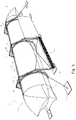
- In 1 is a device 1 for concentrating solar radiation in an absorber 1' (cf. 2 ) shown.
- the device 1 has an inflatable concentrator cushion 2 (cf. Fig. 1b , 1c and 2 ) on.
- the concentrator cushion 2 has a cover film element 3" with a translucent entry window 3 for coupling in solar radiation and a reflector film 6, which divides the concentrator cushion 2 into at least two cavities 4, 5 and is curved in the operating state, for concentrating the solar radiation in an absorber 1' .
- the reflector foil 6 has a mirror surface 6', which bundles the coupled-in solar radiation in the direction of the absorber 1'.
- the absorber 1' which is also understood to be a solar panel, is located in the focus area of the mirror surface 6' within the upper, attached to the Entry window 3 adjoining cavity 4 of the concentrator cushion 2.
- a pipe through which media flows or a photovoltaic element can be provided as the absorber 1'.
- the concentrator cushion 2 is basically designed to be self-supporting when it is filled with compressed air in the cavities 4, 5, so that a considerably lower weight can be achieved compared to conventional solar concentrators.
- the concentrator pad 2 is made up of individual thin-walled (plastic) foils; a transparent film is provided for the entry window 3 .
- a pivoting device 7 for pivoting the concentrator cushion 2 has a plurality of pivoting elements in the form of pivoting rings 8 which enclose the concentrator cushion 2 in the circumferential direction.
- the pivoting rings 8 of the pivoting device 7 together form a tracking system in order to track the concentrator cushion 2 to the course of the sun during operation.
- the pivoting device 7 is set up to move the concentrator cushion 2 about at least one axis of the concentrator cushion 2, here specifically the longitudinal axis of the concentrator cushion 2, to be pivoted.
- an anchoring device 9 is also provided for the pivoting device 7 , with the anchoring device 9 having a suspension device 10 for suspending the pivoting rings 8 of the pivoting device 7 in the embodiment shown.
- the suspension device 10 has a plurality of support frames 11 which are spaced apart in the longitudinal direction of the concentrator cushion 2 and which have attachment points for the pivoting rings 8 of the pivoting device 7 .
- the attachment points are above a plane 7' containing the center of mass (cf. 2 ) of the swivel rings 8 are arranged.
- Each support frame 11 has a first frame member 12 on one longitudinal side of the concentrator pad 2 and a second frame member 13 on the other longitudinal side of the concentrator pad 2 .
- the support frame 11 has a third frame element 14 above the pivoting device 7 with the concentrator cushion 2 .
- the first frame element 12 on one longitudinal side of the concentrator cushion 2 is connected to the second frame element 13 on the other longitudinal side of the concentrator cushion 2 via the third frame element 14 . Accordingly, the support frame 11 extends in an arc from one long side of the concentrator cushion 2 across the concentrator cushion 2 to the other long side of the concentrator cushion 2.
- the first frame element 12 and the second frame element 13 each consist of a first straight or linear frame part 12a, 13a and a second straight or linear frame part 12b, 13b.
- the first frame part 12a, 13a is arranged essentially vertically in the operating state, with the lower end of the first frame part 12a, 13a being mounted in a base element 27.
- the second frame part 12b, 13b is angled inwards from the upper end of the first frame part 12a, 13a, towards the concentrator cushion 2.
- first frame element 12 the second frame element 13 and the third frame element 14 formed as elongated profile elements, which have an I-shaped cross section in the embodiment shown.
- the frame elements 12 , 13 , 14 are arranged in a plane essentially perpendicular to the longitudinal direction of the concentrator cushion 2 .
- the suspension device 10 has a plurality of support frames 11, three in the embodiment shown, which are connected to one another via a plurality of tensioning elements 15 in the form of cable elements.
- the number of support frames 11 depends on the length of the concentrator pad 2.
- the support frames 11 each carry a pivot ring 8 surrounding the concentrator pad 2 .
- the first frame elements 12 of the support frames 11 on one long side of the concentrator cushion 2 are clamped together via clamping elements 15, and on the other hand clamping elements 15 are provided between the second frame elements 13 of the support frames 11 on the other long side of the concentrator cushion 2 .
- two clamping elements 15 are clamped crosswise between the support frame 11 on both longitudinal sides.
- the front support frame 11' and the rear support frame 11", each in relation to the longitudinal direction of the concentrator cushion 2, are braced via further clamping elements 16 on both longitudinal sides of the concentrator cushion 2 on floor elements 17.
- the further clamping elements 16 formed by end portions of clamping elements 15 between the support frame 11.
- pivot bearing devices 18 in the form of roller bearings 19, 20 are provided between the suspension device 10 and the pivot rings 8 of the pivot device 7.
- a first roller bearing 19 is provided on the first frame element 12 of the suspension device 10 and a second roller bearing 20 on the second frame element 13 of the suspension device 10 .
- the swivel rings 8 each have a guide element 21 for the roller bearings 19, 20, with outer roller elements 22 on the upper side of the guide element 21 and inner roller elements 23 roll on the inside of the guide element 21.
- the roller elements 22, 23 of the roller bearings 19, 20 are mounted on trolleys 24 which are attached to the underside of the swivel ring 8.
- the swivel rings 8 each have an I-shaped cross section, with upper flanges 25 of the I-shaped swivel rings 8 being designed as guide elements 21 for the roller bearings 19, 20.
- a covering device 26 is provided on the suspension device 10, which can be transferred between a protective position that at least partially covers the concentrator cushion 2 and a stowed position that essentially completely exposes the concentrator cushion 2.
- a plurality of covering devices 26 are each fastened between two adjacent support frames 11 on the first frame elements 12 on one longitudinal side of the concentrator cushion 2 and on the first frame elements 13 on the other longitudinal side of the concentrator cushion 2 .
- the covering devices 26 consist of a plurality of interconnected lamellar elements which can be transferred between a pushed-together position and a pulled-apart position.
- the two front cover devices 26 are arranged in the pushed together position in which wind forces can act on the lower half of the concentrator cushion 2 .
- the two rear cover devices 26 are arranged in the extended position in which wind forces can be kept away from the lower region of the concentrator cushion 2 .
- the cover devices 26 can be motorized or manually transferred between the stowed position and the protective position.
- the device 1 also has a holding device 31 for the concentrator cushion 2 which has an upper longitudinal member 32 and a lower longitudinal member 33 (in each case in relation to the operating position).
- the upper longitudinal beam 32 In the operating position, the upper longitudinal beam 32 is above the lower one in every angular position of the pivotable pivoting device 7 Longitudinal member 33 arranged.
- the lower longitudinal beam 33 In the non-pivoted starting position of the pivoting device 7 (cf. 2 ) the upper longitudinal beam 32 is located exactly on top, the lower longitudinal beam 33 is positioned exactly on the underside of the concentrator cushion.
- the upper longitudinal member 32 carries the absorber 1' (cf. 2 ), whereas the lower side member 33 contributes to the dissipation of external loads.
- Both longitudinal members 32, 33 extend in the longitudinal direction of the concentrator cushion 2 between a front end piece 2' and a rear end piece 2" on the end faces of the concentrator cushion 2 (cf. 1c ).
- the upper longitudinal beam 32 is suspended on the inside at the upper area of the swivel rings 8 .
- the lower side member 33 is also mounted on the inside, but in the lower area of the swivel rings 8 .
- the upper longitudinal member 32 is connected to an upper side of the concentrator cushion 2 facing the solar radiation.
- the lower longitudinal beam 33 is connected to an underside of the concentrator cushion 2 that faces away from the solar radiation.
- the longitudinal members 32, 33 are designed as trusses in the embodiment shown. How out 2 As can be seen, the longitudinal supports are arranged on a plane 7" which has the center point of the swivel ring 8.
- the upper longitudinal member 32 is arranged at an upper passage opening 34 of the concentrator cushion 2, which is essentially hermetically sealed on all sides.
- the upper longitudinal member 32 has two longitudinal straps 35 running in the longitudinal direction of the concentrator cushion 2 (ie in the direction of its longer extent), which each connect essentially airtight to the longitudinal edges of the concentrator cushion 2 on both sides of the upper passage opening 34 of the cover film element 3".
- the upper longitudinal beam 32 therefore has essentially the same width as the passage opening 34 of the concentrator cushion 2, which extends in the longitudinal direction of the concentrator cushion 2 essentially over its entire length.
- a sealing foil strip 36 is arranged between the longitudinal straps 35, with which the upper passage opening 34 of the concentrator cushion 2 is closed.
- the sealing foil strip 36 is made from a transparent plastic material, in particular from ethylene tetrafluoroethylene (ETFE).
- the lower longitudinal member 33 is arranged on a lower through-opening 34' of the concentrator cushion 2 which is closed in a substantially airtight manner (cf. Fig. 1b ), the lower passage opening 34 ′ extending on a bottom film element 3 ′ of the concentrator cushion 2 bordering on the lower cavity 5 .
- the upper 34 and the lower passage openings 34' have the same longitudinal extent as the upper longitudinal member 32 and the lower longitudinal member 33, respectively.
- the lower longitudinal member 33 is essentially identical in design to the upper longitudinal member 32 .
- the connection between the lower longitudinal member 33 and the base film element 3' is designed in accordance with the connection between the upper longitudinal member 33 and the cover film element 3". The following statements on the upper longitudinal member 32 are therefore to be understood accordingly for the lower longitudinal member 33.
- the upper longitudinal member 32 has two further longitudinal straps 37 which extend parallel to the longitudinal straps 35 in the longitudinal direction of the concentrator cushion 2 .
- the further longitudinal straps 37 of the upper longitudinal beam 32 are arranged within the upper cavity of the concentrator cushion 2 .
- the longitudinal chords 35 and the further longitudinal chords 37 of the upper longitudinal member 32 are connected to one another via filler rods 38 with the formation of intermediate spaces. Further filler rods 39 are provided between the longitudinal chords 35 and the further longitudinal chords 37 .
- profile elements 40 are arranged on the longitudinal belts 35 of the upper longitudinal member.
- Each profile element 40 is on one side with a connecting element 41 for the essentially airtight connection with the adjacent longitudinal edge of the cover film element 3" and on the other side with a further connecting element 42 for the essentially airtight connection with the adjacent longitudinal edge of the sealing foil strip 36 connected.
- the profile element 40 is attached as a separate component on the upper side of the longitudinal belt 35 .
- the profile element 40 is formed in one piece with the longitudinal belt 35 of the upper longitudinal beam 32 .
- retaining elements 40' are provided on the longitudinal straps 35 of the upper longitudinal beam 32 for positive connection with corresponding retaining elements (not shown) on the pivoting device 7 in order to suspend the upper longitudinal beam 32 on the pivoting device 7.
- the profile element 40 for forming the holding elements 40' has holding openings 40'' which extend in the longitudinal direction of the concentrator cushion 2 and in which the corresponding holding elements for connecting the pivoting device are accommodated.
- a piping rail 43 is provided as the connecting element 41, in which a piping element 44 is sealingly accommodated on the associated longitudinal edge of the cover film element 3".
- a further piping rail 45 is correspondingly provided as a further connecting element 42, in which a further piping element 46 forms a seal on the associated longitudinal edge of the sealing film strip 36 is recorded.
- connection element 41 is a zip element 43' for connection to a corresponding zip element 44' on one of the longitudinal edges of the cover film element 3".
- a further zip element 45 ′ for connection to a corresponding further zip element 46 ′ of the sealing film strip 36 is provided as a further connecting element 42 .
- the zipper elements 43 ′, 45 ′ are arranged on the upper side of a profile 47 which extends in the longitudinal direction of the concentrator cushion 2 and which is attached to the longitudinal belt 35 of the upper longitudinal beam 32 on the upper side.
- a clamping part 43" for clamping the associated longitudinal edge of the cover film element 3" is provided as the connecting element 41.
- a further clamping part 45" is provided as a further connecting element 42 for clamping the associated longitudinal edge of the sealing film strip 36.
- a profile part 47' extending in the longitudinal direction of the concentrator cushion 2 is provided on the upper side of the longitudinal belt 35.
- the profile part 47' has Bearing surfaces 47" which cooperate with the clamping part 43" or the further clamping part 45".
- the clamping part 43" is between a position releasing the longitudinal edge of the cover foil element 3" (cf. Figure 8a ) and a position clamping the longitudinal edge of the cover film element 3" (cf.
- an adjustment device 48 is provided between the upper longitudinal member 32, the holding device 31 and the pivoting device 7, with which the distance between the upper longitudinal member 32 and the pivoting device 7 can be adjusted.
- a further adjustment device is provided between the lower longitudinal member 32 and the pivoting device 7 , the following explanations relating to the adjustment device 48 for the upper longitudinal member 32 correspondingly relating to the adjustment of the lower longitudinal member 33 .
- the adjusting device 48 is connected on the one hand to the two longitudinal straps 35 of the upper longitudinal beam 32 and on the other hand to a horizontal fastening flange 49 .
- the adjusting device 48 has an adjusting element in the form of a threaded rod 50 which interacts with threaded nuts 50' in order to be able to set the distance between the upper longitudinal beam 32 and the pivoting device 7 manually.
- the threaded rod 50 is in the execution of 10 arranged essentially perpendicularly to the longitudinal direction of the upper side member 32 .
- the longitudinal straps 35 of the upper longitudinal member 32 are each connected to at least one threaded rod 50 .
- a plurality of toggle lever elements 51 are arranged between the upper longitudinal member 32 and the pivoting device 7, which have leg parts 52 which are connected to one another in an articulated manner at their ends.
- the opening angle between the leg parts 52 of the toggle lever elements 51 is adjusted.
- two toggle lever elements 51 spaced apart in the longitudinal direction are fastened to both longitudinal straps 35 and are coupled to one another via at least one adjustment element 53 in the form of a threaded rod.
- the threaded rod By adjusting the threaded rod, the opening angle of the toggle lever elements 51 and thus the distance between the pivoting device 7 and the upper longitudinal beam 32 can be adjusted.
- two adjusting elements 53 are arranged horizontally, essentially parallel to the longitudinal direction of the upper side member 32 .
- toggle lever elements 53 are connected to one another in pairs via connecting rods 54 on the opposite longitudinal straps 35 of the upper longitudinal beam 32 .
- two adjusting elements 53 are provided in the form of threaded rods which are adjustably connected to the connecting rods 54 .
- the adjusting device 48 has a drive element 55, with which the distance between the pivoting device 7 and the upper longitudinal member 32 can be automatically adjusted depending on a load condition of the upper longitudinal member 32 (i.e. in particular dependent on a vertical force as a result of the creeping of the concentrator cushion 2).
- a spring element 55′ is provided as the drive element 55 in such a way that the upper longitudinal member 32 can be brought closer to the swivel ring 8 against the force of the spring element 55′, depending on the load condition of the upper longitudinal member 32 .
- the adjustment elements 53 between the connecting rods 54 are designed as drive elements 55 .
Landscapes
- Engineering & Computer Science (AREA)
- Sustainable Development (AREA)
- Life Sciences & Earth Sciences (AREA)
- Chemical & Material Sciences (AREA)
- Sustainable Energy (AREA)
- Thermal Sciences (AREA)
- Physics & Mathematics (AREA)
- Combustion & Propulsion (AREA)
- Mechanical Engineering (AREA)
- General Engineering & Computer Science (AREA)
- Optical Elements Other Than Lenses (AREA)
- Tents Or Canopies (AREA)
- Air Bags (AREA)
Claims (10)
- Dispositif (1) de concentration du rayonnement solaire dans un absorbeur (1') avec un coussin concentrateur gonflable (2), qui comporte un élément de feuille de recouvrement (3") avec une fenêtre d'entrée transparente (3) pour l'injection du rayonnement solaire et une feuille formant réflecteur (6) divisant le coussin concentrateur (2) en au moins deux cavités (4, 5) pour concentrer le rayonnement solaire dans un absorbeur (1'), avec un dispositif pivotant (7) avec lequel le coussin concentrateur (2) peut pivoter en particulier autour de son axe longitudinal, et avec un dispositif de maintien (31) fixé au dispositif pivotant pour maintenir le coussin concentrateur (2), où le dispositif de maintien (31) comporte un longeron supérieur (32) qui s'étend dans la direction longitudinale du coussin concentrateur (2), qui est disposé au niveau d'une ouverture de passage supérieure (34) fermée de manière sensiblement étanche à l'air, et un longeron inférieur (33) qui s'étend dans la direction longitudinale du coussin concentrateur (2), qui est disposé au niveau d'une ouverture de passage inférieure (34') fermée de manière sensiblement étanche à l'air,où le longeron supérieur (32) est relié avec les bords longitudinaux de l'élément de feuille de recouvrement (3") limitant l'ouverture de passage supérieure (34) et le longeron inférieur (33) est relié avec les bords longitudinaux d'un élément de feuille de fond (3') du coussin concentrateur (2) limitant l'ouverture de passage inférieure (34'),où le dispositif pivotant (7) comporte au moins un élément pivotant, en particulier un anneau pivotant (8), entourant le coussin concentrateur (2) dans sa direction circonférentielle, sur le côté intérieur duquel sont fixés le longeron supérieur (32) et le longeron inférieur (33) du dispositif de maintien (31).
- Dispositif (1) selon la revendication 1, caractérisé en ce que plusieurs éléments pivotants, en particulier des anneaux pivotants (8), espacés dans la direction longitudinale du coussin concentrateur (2), sont prévus, sur le côté intérieur desquels sont fixés le longeron supérieur (32) et le longeron inférieur (33) du dispositif de maintien (31).
- Dispositif (1) selon l'une des revendications 1 à 2, caractérisé en ce que le longeron supérieur (32) et/ou le longeron inférieur (33) s'étend au moins sur plus de la moitié de la longueur du coussin concentrateur (2), où le longeron supérieur (32) et/ou le longeron inférieur (33) s'étend de préférence entre un embout avant (2') et un embout arrière (2") sur les côtés frontaux du coussin concentrateur (2).
- Dispositif (1) selon l'une des revendications 1 à 3, caractérisé en ce que le longeron supérieur (32) et/ou le longeron inférieur (33) comporte des membrures longitudinales (35) reliées entre elles par l'intermédiaire de barres transversales (38), où une bande de feuille étanche (36) qui forme un pont sur l'ouverture de passage supérieure (34) ou l'ouverture de passage inférieure (34') du coussin concentrateur (2) est prévue entre les membrures longitudinales (35).
- Dispositif (1) selon l'une des revendications 1 à 4, caractérisé en ce que sur les membrures longitudinales (35) du longeron supérieur (32) est disposé dans chaque cas un élément profilé (40) qui est relié sur un côté avec un élément de liaison (41) pour la liaison sensiblement étanche à l'air avec l'un des bords longitudinaux de l'élément de feuille de recouvrement (3") et sur l'autre côté avec un autre élément de liaison (42) pour la liaison sensiblement étanche à l'air avec l'un des bords longitudinaux de la bande de feuille étanche (36).
- Dispositif (1) selon l'une des revendications 1 à 5, caractérisé en ce que le longeron supérieur (32) et/ou le longeron inférieur (33) comporte au moins deux autres membrures longitudinales (37) qui s'étendent parallèlement aux membrures longitudinales (35) dans la direction longitudinale du coussin concentrateur (2).
- Dispositif (1) selon la revendication 6, caractérisé en ce que les autres membrures longitudinales (37) du longeron supérieur (32) sont disposées à l'intérieur de la cavité supérieure (4) et/ou les autres membrures longitudinales (37) du longeron inférieur (33) sont disposées à l'intérieur de la cavité inférieure (5) du coussin concentrateur (2).
- Dispositif (1) selon l'une des revendications 1 à 7, caractérisé en ce qu'entre le longeron supérieur (32) du dispositif de maintien (31) et le dispositif pivotant (7) est prévu un dispositif de réglage (48) avec lequel la distance entre le longeron supérieur (32) et le dispositif pivotant (7) est réglable, et/ou en ce qu'un autre dispositif de réglage (48) est prévu entre le longeron inférieur (33) du dispositif de maintien (31) et le dispositif pivotant (7), avec lequel la distance entre le longeron inférieur (33) et le dispositif pivotant (7) est réglable.
- Dispositif (1) selon l'une des revendications 1 à 8, caractérisé en ce qu'il est prévu un dispositif d'ancrage (9) pour ancrer le dispositif pivotant (7) à une structure de fond, qui comporte de préférence un dispositif de suspension (10) pour suspendre le dispositif pivotant (7).
- Dispositif (1) selon l'une des revendications 1 à 9, caractérisé en ce qu'il est prévu entre le dispositif de suspension (10) et le dispositif pivotant (7) un dispositif à palier pivotant (18), en particulier un roulement à rouleaux (19, 20).
Applications Claiming Priority (2)
| Application Number | Priority Date | Filing Date | Title |
|---|---|---|---|
| EP14191240.2A EP3015787A1 (fr) | 2014-10-31 | 2014-10-31 | Dispositif de concentration du rayonnement solaire avec coussin gonflable de concentration |
| PCT/EP2015/075206 WO2016066783A1 (fr) | 2014-10-31 | 2015-10-30 | Dispositif de concentration de rayonnement solaire doté d'un coussin gonflable à concentrateur |
Publications (2)
| Publication Number | Publication Date |
|---|---|
| EP3213009A1 EP3213009A1 (fr) | 2017-09-06 |
| EP3213009B1 true EP3213009B1 (fr) | 2022-12-07 |
Family
ID=51844582
Family Applications (2)
| Application Number | Title | Priority Date | Filing Date |
|---|---|---|---|
| EP14191240.2A Withdrawn EP3015787A1 (fr) | 2014-10-31 | 2014-10-31 | Dispositif de concentration du rayonnement solaire avec coussin gonflable de concentration |
| EP15788012.1A Active EP3213009B1 (fr) | 2014-10-31 | 2015-10-30 | Dispositif de concentration du rayonnement solaire avec coussin gonflable de concentration |
Family Applications Before (1)
| Application Number | Title | Priority Date | Filing Date |
|---|---|---|---|
| EP14191240.2A Withdrawn EP3015787A1 (fr) | 2014-10-31 | 2014-10-31 | Dispositif de concentration du rayonnement solaire avec coussin gonflable de concentration |
Country Status (7)
| Country | Link |
|---|---|
| US (1) | US11402129B2 (fr) |
| EP (2) | EP3015787A1 (fr) |
| CN (1) | CN107148542B (fr) |
| AU (1) | AU2015340553B2 (fr) |
| ES (1) | ES2936083T3 (fr) |
| MA (1) | MA40855A (fr) |
| WO (1) | WO2016066783A1 (fr) |
Families Citing this family (4)
| Publication number | Priority date | Publication date | Assignee | Title |
|---|---|---|---|---|
| EP3015788A1 (fr) * | 2014-10-31 | 2016-05-04 | Heliovis AG | Dispositif de concentration du rayonnement solaire avec coussin gonflable de concentration |
| EP3015787A1 (fr) | 2014-10-31 | 2016-05-04 | Heliovis AG | Dispositif de concentration du rayonnement solaire avec coussin gonflable de concentration |
| EP3015789A1 (fr) * | 2014-10-31 | 2016-05-04 | Heliovis AG | Dispositif de concentration du rayonnement solaire avec coussin gonflable de concentration |
| WO2021184204A1 (fr) * | 2020-03-15 | 2021-09-23 | 南京索乐优节能科技有限公司 | Dispositif collecteur de chaleur cpc gonflable |
Family Cites Families (18)
| Publication number | Priority date | Publication date | Assignee | Title |
|---|---|---|---|---|
| NL1008356C2 (nl) * | 1998-02-19 | 1999-08-20 | Suria Holdings Sarl | Inrichting voor het verwarmen met zonne-energie. |
| US8056555B2 (en) * | 2006-04-12 | 2011-11-15 | Prueitt Melvin L | Thin film trough solar collector |
| US7997264B2 (en) * | 2007-01-10 | 2011-08-16 | Ric Enterprises | Inflatable heliostatic solar power collector |
| AT505075B1 (de) | 2007-03-30 | 2009-01-15 | Hoefler Johannes | Aufblasbarer sonnenkollektor |
| WO2009117840A2 (fr) * | 2008-03-28 | 2009-10-01 | Ale Airlight Energy Sa | Capteur cylindro-parabolique pour centrale solaire |
| US8333186B2 (en) | 2008-09-18 | 2012-12-18 | Kevin Jennings | Parabolic trough solar reflector with an independently supported collector tube |
| US20110100358A1 (en) | 2009-09-04 | 2011-05-05 | Randal Jerome Perisho | Low Cost Fixed Focal Point Parabolic Trough |
| AT509638B1 (de) * | 2010-03-05 | 2014-08-15 | Heliovis Ag | Kissenförmiger konzentrator zur bündelung elektromagnetischer strahlung |
| US9404677B2 (en) * | 2010-05-17 | 2016-08-02 | Ric Enterprises | Inflatable linear heliostatic concentrating solar module |
| CN103229000B (zh) | 2010-07-05 | 2016-07-06 | 玻点太阳能有限公司 | 温室的聚光太阳能发电 |
| AT511007B1 (de) * | 2010-12-20 | 2012-11-15 | Heliovis Ag | Aufblasbarer konzentrator zur bündelung von strahlung sowie verfahren zu dessen herstellung |
| CH704394A2 (de) | 2011-01-28 | 2012-07-31 | Airlight Energy Ip Sa | Verfahren und Vorrichtung zur Messung der Reflektionseigenschaften eines Reflektors. |
| AT511467B1 (de) * | 2011-04-29 | 2012-12-15 | Heliovis Ag | Vorrichtung zur konzentration von sonnenstrahlung in einem absorber |
| US20130314774A1 (en) * | 2011-11-16 | 2013-11-28 | Cool Earth Solar Inc. | Inflated tubular solar concentrators |
| ES2446890B1 (es) | 2012-09-07 | 2014-12-16 | Abengoa Solar New Technologies S.A. | Estructura soporte para colector solar cilíndrico de concentración y colector solar que comprende la mencionada estructura |
| EP3015788A1 (fr) * | 2014-10-31 | 2016-05-04 | Heliovis AG | Dispositif de concentration du rayonnement solaire avec coussin gonflable de concentration |
| EP3015787A1 (fr) | 2014-10-31 | 2016-05-04 | Heliovis AG | Dispositif de concentration du rayonnement solaire avec coussin gonflable de concentration |
| EP3015789A1 (fr) * | 2014-10-31 | 2016-05-04 | Heliovis AG | Dispositif de concentration du rayonnement solaire avec coussin gonflable de concentration |
-
2014
- 2014-10-31 EP EP14191240.2A patent/EP3015787A1/fr not_active Withdrawn
-
2015
- 2015-10-29 MA MA040855A patent/MA40855A/fr unknown
- 2015-10-30 EP EP15788012.1A patent/EP3213009B1/fr active Active
- 2015-10-30 WO PCT/EP2015/075206 patent/WO2016066783A1/fr not_active Ceased
- 2015-10-30 AU AU2015340553A patent/AU2015340553B2/en active Active
- 2015-10-30 ES ES15788012T patent/ES2936083T3/es active Active
- 2015-10-30 CN CN201580058850.XA patent/CN107148542B/zh active Active
- 2015-10-30 US US15/523,278 patent/US11402129B2/en active Active
Also Published As
| Publication number | Publication date |
|---|---|
| ES2936083T3 (es) | 2023-03-14 |
| US11402129B2 (en) | 2022-08-02 |
| AU2015340553A1 (en) | 2017-05-25 |
| CN107148542A (zh) | 2017-09-08 |
| US20170336100A1 (en) | 2017-11-23 |
| MA40855A (fr) | 2017-09-05 |
| AU2015340553B2 (en) | 2020-05-14 |
| WO2016066783A1 (fr) | 2016-05-06 |
| EP3015787A1 (fr) | 2016-05-04 |
| EP3213009A1 (fr) | 2017-09-06 |
| CN107148542B (zh) | 2019-10-25 |
Similar Documents
| Publication | Publication Date | Title |
|---|---|---|
| DE102007026473B4 (de) | Parabolrinnenkollektor | |
| EP3213009B1 (fr) | Dispositif de concentration du rayonnement solaire avec coussin gonflable de concentration | |
| DE2939203A1 (de) | Sonnenenergiekollektor | |
| WO2012145774A2 (fr) | Dispositif pour la concentration du rayonnement solaire dans un absorbeur | |
| EP3213008B1 (fr) | Dispositif de concentration du rayonnement solaire avec coussin gonflable de concentration | |
| WO2009068307A1 (fr) | Structure d'appui pour des capteurs solaires, en particulier pour des capteurs solaires à lentilles de fresnel | |
| DE202010015817U1 (de) | Solarmodulanordnung | |
| DE102008051807B4 (de) | Parabolrinnenkollektor | |
| EP3213010B1 (fr) | Dispositif pour ancrer un coussin gonflable à concentrateur | |
| EP3213007B1 (fr) | Dispositif de concentration du rayonnement solaire avec coussin gonflable de concentration | |
| WO2014037272A1 (fr) | Dispositif de support | |
| EP3234477B1 (fr) | Dispositif de concentration du rayonnement solaire | |
| CN205348490U (zh) | 索承重大跨度玻璃幕墙连接结构 | |
| DE112005002488T5 (de) | Verfahren und Vorrichtung zur Vermeidung der Verwindung eines gerahmten Solarmoduls | |
| DE102006050456B4 (de) | Flachdachaufsatz mit Solarmodulen | |
| AT517230B1 (de) | Solarkraftwerk zur Umwandlung von Sonnenenergie in nutzbare Energie | |
| AT522960B1 (de) | Parabolrinnenkollektor | |
| WO2022184724A1 (fr) | Structure de support flottante pour modules photovoltaïques |
Legal Events
| Date | Code | Title | Description |
|---|---|---|---|
| STAA | Information on the status of an ep patent application or granted ep patent |
Free format text: STATUS: THE INTERNATIONAL PUBLICATION HAS BEEN MADE |
|
| PUAI | Public reference made under article 153(3) epc to a published international application that has entered the european phase |
Free format text: ORIGINAL CODE: 0009012 |
|
| STAA | Information on the status of an ep patent application or granted ep patent |
Free format text: STATUS: REQUEST FOR EXAMINATION WAS MADE |
|
| 17P | Request for examination filed |
Effective date: 20170523 |
|
| AK | Designated contracting states |
Kind code of ref document: A1 Designated state(s): AL AT BE BG CH CY CZ DE DK EE ES FI FR GB GR HR HU IE IS IT LI LT LU LV MC MK MT NL NO PL PT RO RS SE SI SK SM TR |
|
| AX | Request for extension of the european patent |
Extension state: BA ME |
|
| DAX | Request for extension of the european patent (deleted) | ||
| STAA | Information on the status of an ep patent application or granted ep patent |
Free format text: STATUS: EXAMINATION IS IN PROGRESS |
|
| 17Q | First examination report despatched |
Effective date: 20201201 |
|
| REG | Reference to a national code |
Ref country code: DE Ref legal event code: R079 Ref document number: 502015016187 Country of ref document: DE Free format text: PREVIOUS MAIN CLASS: F24J0002140000 Ipc: F24S0030425000 |
|
| RIC1 | Information provided on ipc code assigned before grant |
Ipc: F24S 30/00 20180101ALN20220523BHEP Ipc: F24S 20/80 20180101ALI20220523BHEP Ipc: F24S 23/74 20180101ALI20220523BHEP Ipc: F24S 25/13 20180101ALI20220523BHEP Ipc: F24S 30/425 20180101AFI20220523BHEP |
|
| GRAP | Despatch of communication of intention to grant a patent |
Free format text: ORIGINAL CODE: EPIDOSNIGR1 |
|
| STAA | Information on the status of an ep patent application or granted ep patent |
Free format text: STATUS: GRANT OF PATENT IS INTENDED |
|
| RIC1 | Information provided on ipc code assigned before grant |
Ipc: F24S 30/00 20180101ALN20220601BHEP Ipc: F24S 20/80 20180101ALI20220601BHEP Ipc: F24S 23/74 20180101ALI20220601BHEP Ipc: F24S 25/13 20180101ALI20220601BHEP Ipc: F24S 30/425 20180101AFI20220601BHEP |
|
| INTG | Intention to grant announced |
Effective date: 20220704 |
|
| GRAS | Grant fee paid |
Free format text: ORIGINAL CODE: EPIDOSNIGR3 |
|
| GRAA | (expected) grant |
Free format text: ORIGINAL CODE: 0009210 |
|
| STAA | Information on the status of an ep patent application or granted ep patent |
Free format text: STATUS: THE PATENT HAS BEEN GRANTED |
|
| AK | Designated contracting states |
Kind code of ref document: B1 Designated state(s): AL AT BE BG CH CY CZ DE DK EE ES FI FR GB GR HR HU IE IS IT LI LT LU LV MC MK MT NL NO PL PT RO RS SE SI SK SM TR |
|
| REG | Reference to a national code |
Ref country code: GB Ref legal event code: FG4D Free format text: NOT ENGLISH |
|
| REG | Reference to a national code |
Ref country code: CH Ref legal event code: EP Ref country code: AT Ref legal event code: REF Ref document number: 1536528 Country of ref document: AT Kind code of ref document: T Effective date: 20221215 |
|
| REG | Reference to a national code |
Ref country code: DE Ref legal event code: R096 Ref document number: 502015016187 Country of ref document: DE |
|
| REG | Reference to a national code |
Ref country code: IE Ref legal event code: FG4D Free format text: LANGUAGE OF EP DOCUMENT: GERMAN |
|
| REG | Reference to a national code |
Ref country code: ES Ref legal event code: FG2A Ref document number: 2936083 Country of ref document: ES Kind code of ref document: T3 Effective date: 20230314 |
|
| REG | Reference to a national code |
Ref country code: LT Ref legal event code: MG9D |
|
| REG | Reference to a national code |
Ref country code: NL Ref legal event code: MP Effective date: 20221207 |
|
| PG25 | Lapsed in a contracting state [announced via postgrant information from national office to epo] |
Ref country code: SE Free format text: LAPSE BECAUSE OF FAILURE TO SUBMIT A TRANSLATION OF THE DESCRIPTION OR TO PAY THE FEE WITHIN THE PRESCRIBED TIME-LIMIT Effective date: 20221207 Ref country code: NO Free format text: LAPSE BECAUSE OF FAILURE TO SUBMIT A TRANSLATION OF THE DESCRIPTION OR TO PAY THE FEE WITHIN THE PRESCRIBED TIME-LIMIT Effective date: 20230307 Ref country code: LT Free format text: LAPSE BECAUSE OF FAILURE TO SUBMIT A TRANSLATION OF THE DESCRIPTION OR TO PAY THE FEE WITHIN THE PRESCRIBED TIME-LIMIT Effective date: 20221207 Ref country code: FI Free format text: LAPSE BECAUSE OF FAILURE TO SUBMIT A TRANSLATION OF THE DESCRIPTION OR TO PAY THE FEE WITHIN THE PRESCRIBED TIME-LIMIT Effective date: 20221207 |
|
| PG25 | Lapsed in a contracting state [announced via postgrant information from national office to epo] |
Ref country code: RS Free format text: LAPSE BECAUSE OF FAILURE TO SUBMIT A TRANSLATION OF THE DESCRIPTION OR TO PAY THE FEE WITHIN THE PRESCRIBED TIME-LIMIT Effective date: 20221207 Ref country code: PL Free format text: LAPSE BECAUSE OF FAILURE TO SUBMIT A TRANSLATION OF THE DESCRIPTION OR TO PAY THE FEE WITHIN THE PRESCRIBED TIME-LIMIT Effective date: 20221207 Ref country code: LV Free format text: LAPSE BECAUSE OF FAILURE TO SUBMIT A TRANSLATION OF THE DESCRIPTION OR TO PAY THE FEE WITHIN THE PRESCRIBED TIME-LIMIT Effective date: 20221207 Ref country code: HR Free format text: LAPSE BECAUSE OF FAILURE TO SUBMIT A TRANSLATION OF THE DESCRIPTION OR TO PAY THE FEE WITHIN THE PRESCRIBED TIME-LIMIT Effective date: 20221207 Ref country code: GR Free format text: LAPSE BECAUSE OF FAILURE TO SUBMIT A TRANSLATION OF THE DESCRIPTION OR TO PAY THE FEE WITHIN THE PRESCRIBED TIME-LIMIT Effective date: 20230308 |
|
| P01 | Opt-out of the competence of the unified patent court (upc) registered |
Effective date: 20230516 |
|
| PG25 | Lapsed in a contracting state [announced via postgrant information from national office to epo] |
Ref country code: NL Free format text: LAPSE BECAUSE OF FAILURE TO SUBMIT A TRANSLATION OF THE DESCRIPTION OR TO PAY THE FEE WITHIN THE PRESCRIBED TIME-LIMIT Effective date: 20221207 |
|
| PG25 | Lapsed in a contracting state [announced via postgrant information from national office to epo] |
Ref country code: SM Free format text: LAPSE BECAUSE OF FAILURE TO SUBMIT A TRANSLATION OF THE DESCRIPTION OR TO PAY THE FEE WITHIN THE PRESCRIBED TIME-LIMIT Effective date: 20221207 Ref country code: RO Free format text: LAPSE BECAUSE OF FAILURE TO SUBMIT A TRANSLATION OF THE DESCRIPTION OR TO PAY THE FEE WITHIN THE PRESCRIBED TIME-LIMIT Effective date: 20221207 Ref country code: PT Free format text: LAPSE BECAUSE OF FAILURE TO SUBMIT A TRANSLATION OF THE DESCRIPTION OR TO PAY THE FEE WITHIN THE PRESCRIBED TIME-LIMIT Effective date: 20230410 Ref country code: EE Free format text: LAPSE BECAUSE OF FAILURE TO SUBMIT A TRANSLATION OF THE DESCRIPTION OR TO PAY THE FEE WITHIN THE PRESCRIBED TIME-LIMIT Effective date: 20221207 Ref country code: CZ Free format text: LAPSE BECAUSE OF FAILURE TO SUBMIT A TRANSLATION OF THE DESCRIPTION OR TO PAY THE FEE WITHIN THE PRESCRIBED TIME-LIMIT Effective date: 20221207 |
|
| PG25 | Lapsed in a contracting state [announced via postgrant information from national office to epo] |
Ref country code: SK Free format text: LAPSE BECAUSE OF FAILURE TO SUBMIT A TRANSLATION OF THE DESCRIPTION OR TO PAY THE FEE WITHIN THE PRESCRIBED TIME-LIMIT Effective date: 20221207 Ref country code: IS Free format text: LAPSE BECAUSE OF FAILURE TO SUBMIT A TRANSLATION OF THE DESCRIPTION OR TO PAY THE FEE WITHIN THE PRESCRIBED TIME-LIMIT Effective date: 20230407 Ref country code: AL Free format text: LAPSE BECAUSE OF FAILURE TO SUBMIT A TRANSLATION OF THE DESCRIPTION OR TO PAY THE FEE WITHIN THE PRESCRIBED TIME-LIMIT Effective date: 20221207 |
|
| REG | Reference to a national code |
Ref country code: DE Ref legal event code: R097 Ref document number: 502015016187 Country of ref document: DE |
|
| PLBE | No opposition filed within time limit |
Free format text: ORIGINAL CODE: 0009261 |
|
| STAA | Information on the status of an ep patent application or granted ep patent |
Free format text: STATUS: NO OPPOSITION FILED WITHIN TIME LIMIT |
|
| PG25 | Lapsed in a contracting state [announced via postgrant information from national office to epo] |
Ref country code: DK Free format text: LAPSE BECAUSE OF FAILURE TO SUBMIT A TRANSLATION OF THE DESCRIPTION OR TO PAY THE FEE WITHIN THE PRESCRIBED TIME-LIMIT Effective date: 20221207 |
|
| 26N | No opposition filed |
Effective date: 20230908 |
|
| PG25 | Lapsed in a contracting state [announced via postgrant information from national office to epo] |
Ref country code: SI Free format text: LAPSE BECAUSE OF FAILURE TO SUBMIT A TRANSLATION OF THE DESCRIPTION OR TO PAY THE FEE WITHIN THE PRESCRIBED TIME-LIMIT Effective date: 20221207 |
|
| PG25 | Lapsed in a contracting state [announced via postgrant information from national office to epo] |
Ref country code: IT Free format text: LAPSE BECAUSE OF FAILURE TO SUBMIT A TRANSLATION OF THE DESCRIPTION OR TO PAY THE FEE WITHIN THE PRESCRIBED TIME-LIMIT Effective date: 20221207 Ref country code: MC Free format text: LAPSE BECAUSE OF FAILURE TO SUBMIT A TRANSLATION OF THE DESCRIPTION OR TO PAY THE FEE WITHIN THE PRESCRIBED TIME-LIMIT Effective date: 20221207 |
|
| REG | Reference to a national code |
Ref country code: CH Ref legal event code: PL |
|
| REG | Reference to a national code |
Ref country code: BE Ref legal event code: MM Effective date: 20231031 |
|
| PG25 | Lapsed in a contracting state [announced via postgrant information from national office to epo] |
Ref country code: LU Free format text: LAPSE BECAUSE OF NON-PAYMENT OF DUE FEES Effective date: 20231030 |
|
| GBPC | Gb: european patent ceased through non-payment of renewal fee |
Effective date: 20231030 |
|
| PG25 | Lapsed in a contracting state [announced via postgrant information from national office to epo] |
Ref country code: LU Free format text: LAPSE BECAUSE OF NON-PAYMENT OF DUE FEES Effective date: 20231030 |
|
| PG25 | Lapsed in a contracting state [announced via postgrant information from national office to epo] |
Ref country code: GB Free format text: LAPSE BECAUSE OF NON-PAYMENT OF DUE FEES Effective date: 20231030 |
|
| PG25 | Lapsed in a contracting state [announced via postgrant information from national office to epo] |
Ref country code: CH Free format text: LAPSE BECAUSE OF NON-PAYMENT OF DUE FEES Effective date: 20231031 |
|
| PG25 | Lapsed in a contracting state [announced via postgrant information from national office to epo] |
Ref country code: GB Free format text: LAPSE BECAUSE OF NON-PAYMENT OF DUE FEES Effective date: 20231030 Ref country code: FR Free format text: LAPSE BECAUSE OF NON-PAYMENT OF DUE FEES Effective date: 20231031 Ref country code: CH Free format text: LAPSE BECAUSE OF NON-PAYMENT OF DUE FEES Effective date: 20231031 |
|
| PG25 | Lapsed in a contracting state [announced via postgrant information from national office to epo] |
Ref country code: BE Free format text: LAPSE BECAUSE OF NON-PAYMENT OF DUE FEES Effective date: 20231031 |
|
| PG25 | Lapsed in a contracting state [announced via postgrant information from national office to epo] |
Ref country code: IE Free format text: LAPSE BECAUSE OF NON-PAYMENT OF DUE FEES Effective date: 20231030 |
|
| PG25 | Lapsed in a contracting state [announced via postgrant information from national office to epo] |
Ref country code: IE Free format text: LAPSE BECAUSE OF NON-PAYMENT OF DUE FEES Effective date: 20231030 |
|
| PG25 | Lapsed in a contracting state [announced via postgrant information from national office to epo] |
Ref country code: BG Free format text: LAPSE BECAUSE OF FAILURE TO SUBMIT A TRANSLATION OF THE DESCRIPTION OR TO PAY THE FEE WITHIN THE PRESCRIBED TIME-LIMIT Effective date: 20221207 |
|
| PG25 | Lapsed in a contracting state [announced via postgrant information from national office to epo] |
Ref country code: BG Free format text: LAPSE BECAUSE OF FAILURE TO SUBMIT A TRANSLATION OF THE DESCRIPTION OR TO PAY THE FEE WITHIN THE PRESCRIBED TIME-LIMIT Effective date: 20221207 |
|
| REG | Reference to a national code |
Ref country code: AT Ref legal event code: MM01 Ref document number: 1536528 Country of ref document: AT Kind code of ref document: T Effective date: 20231030 |
|
| PGFP | Annual fee paid to national office [announced via postgrant information from national office to epo] |
Ref country code: DE Payment date: 20241022 Year of fee payment: 10 |
|
| PG25 | Lapsed in a contracting state [announced via postgrant information from national office to epo] |
Ref country code: AT Free format text: LAPSE BECAUSE OF NON-PAYMENT OF DUE FEES Effective date: 20231030 |
|
| PGFP | Annual fee paid to national office [announced via postgrant information from national office to epo] |
Ref country code: ES Payment date: 20241118 Year of fee payment: 10 |
|
| PG25 | Lapsed in a contracting state [announced via postgrant information from national office to epo] |
Ref country code: AT Free format text: LAPSE BECAUSE OF NON-PAYMENT OF DUE FEES Effective date: 20231030 |
|
| PG25 | Lapsed in a contracting state [announced via postgrant information from national office to epo] |
Ref country code: CY Free format text: LAPSE BECAUSE OF FAILURE TO SUBMIT A TRANSLATION OF THE DESCRIPTION OR TO PAY THE FEE WITHIN THE PRESCRIBED TIME-LIMIT; INVALID AB INITIO Effective date: 20151030 |
|
| PG25 | Lapsed in a contracting state [announced via postgrant information from national office to epo] |
Ref country code: HU Free format text: LAPSE BECAUSE OF FAILURE TO SUBMIT A TRANSLATION OF THE DESCRIPTION OR TO PAY THE FEE WITHIN THE PRESCRIBED TIME-LIMIT; INVALID AB INITIO Effective date: 20151030 |
|
| VS25 | Lapsed in a validation state [announced via postgrant information from nat. office to epo] |
Ref country code: MA Free format text: FAILURE TO ELECT DOMICILE IN THE NATIONAL COUNTRY Effective date: 20230308 |
|
| PG25 | Lapsed in a contracting state [announced via postgrant information from national office to epo] |
Ref country code: TR Free format text: LAPSE BECAUSE OF FAILURE TO SUBMIT A TRANSLATION OF THE DESCRIPTION OR TO PAY THE FEE WITHIN THE PRESCRIBED TIME-LIMIT Effective date: 20221207 |