EP3213336B1 - Disjoncteur de protection pyrotechnique - Google Patents
Disjoncteur de protection pyrotechnique Download PDFInfo
- Publication number
- EP3213336B1 EP3213336B1 EP15800726.0A EP15800726A EP3213336B1 EP 3213336 B1 EP3213336 B1 EP 3213336B1 EP 15800726 A EP15800726 A EP 15800726A EP 3213336 B1 EP3213336 B1 EP 3213336B1
- Authority
- EP
- European Patent Office
- Prior art keywords
- sheet metal
- pyrotechnic
- circuit breaker
- current carrying
- carrying sheet
- Prior art date
- Legal status (The legal status is an assumption and is not a legal conclusion. Google has not performed a legal analysis and makes no representation as to the accuracy of the status listed.)
- Not-in-force
Links
Images


Classifications
-
- H—ELECTRICITY
- H01—ELECTRIC ELEMENTS
- H01H—ELECTRIC SWITCHES; RELAYS; SELECTORS; EMERGENCY PROTECTIVE DEVICES
- H01H39/00—Switching devices actuated by an explosion produced within the device and initiated by an electric current
- H01H39/006—Opening by severing a conductor
-
- H—ELECTRICITY
- H01—ELECTRIC ELEMENTS
- H01H—ELECTRIC SWITCHES; RELAYS; SELECTORS; EMERGENCY PROTECTIVE DEVICES
- H01H1/00—Contacts
- H01H1/58—Electric connections to or between contacts; Terminals
- H01H1/5866—Electric connections to or between contacts; Terminals characterised by the use of a plug and socket connector
-
- H—ELECTRICITY
- H01—ELECTRIC ELEMENTS
- H01R—ELECTRICALLY-CONDUCTIVE CONNECTIONS; STRUCTURAL ASSOCIATIONS OF A PLURALITY OF MUTUALLY-INSULATED ELECTRICAL CONNECTING ELEMENTS; COUPLING DEVICES; CURRENT COLLECTORS
- H01R31/00—Coupling parts supported only by co-operation with counterpart
- H01R31/08—Short-circuiting members for bridging contacts in a counterpart
-
- B—PERFORMING OPERATIONS; TRANSPORTING
- B60—VEHICLES IN GENERAL
- B60R—VEHICLES, VEHICLE FITTINGS, OR VEHICLE PARTS, NOT OTHERWISE PROVIDED FOR
- B60R16/00—Electric or fluid circuits specially adapted for vehicles and not otherwise provided for; Arrangement of elements of electric or fluid circuits specially adapted for vehicles and not otherwise provided for
- B60R16/02—Electric or fluid circuits specially adapted for vehicles and not otherwise provided for; Arrangement of elements of electric or fluid circuits specially adapted for vehicles and not otherwise provided for electric constitutive elements
- B60R16/03—Electric or fluid circuits specially adapted for vehicles and not otherwise provided for; Arrangement of elements of electric or fluid circuits specially adapted for vehicles and not otherwise provided for electric constitutive elements for supply of electrical power to vehicle subsystems or for
-
- H—ELECTRICITY
- H01—ELECTRIC ELEMENTS
- H01H—ELECTRIC SWITCHES; RELAYS; SELECTORS; EMERGENCY PROTECTIVE DEVICES
- H01H39/00—Switching devices actuated by an explosion produced within the device and initiated by an electric current
- H01H2039/008—Switching devices actuated by an explosion produced within the device and initiated by an electric current using the switch for a battery cutoff
-
- H—ELECTRICITY
- H01—ELECTRIC ELEMENTS
- H01R—ELECTRICALLY-CONDUCTIVE CONNECTIONS; STRUCTURAL ASSOCIATIONS OF A PLURALITY OF MUTUALLY-INSULATED ELECTRICAL CONNECTING ELEMENTS; COUPLING DEVICES; CURRENT COLLECTORS
- H01R13/00—Details of coupling devices of the kinds covered by groups H01R12/70 or H01R24/00 - H01R33/00
- H01R13/62—Means for facilitating engagement or disengagement of coupling parts or for holding them in engagement
- H01R13/629—Additional means for facilitating engagement or disengagement of coupling parts, e.g. aligning or guiding means, levers, gas pressure electrical locking indicators, manufacturing tolerances
- H01R13/633—Additional means for facilitating engagement or disengagement of coupling parts, e.g. aligning or guiding means, levers, gas pressure electrical locking indicators, manufacturing tolerances for disengagement only
- H01R13/637—Additional means for facilitating engagement or disengagement of coupling parts, e.g. aligning or guiding means, levers, gas pressure electrical locking indicators, manufacturing tolerances for disengagement only by fluid pressure, e.g. explosion
Definitions
- the invention relates to a pyrotechnic circuit breaker, in particular for a motor vehicle.
- a pyrotechnic circuit breaker also called a pyrotechnic fuse element
- the pyrotechnic safety switch also called pyrotechnic safety switch, pyrotechnic disconnecting element or pyrotechnic switch for short, is a type of emergency stop switch of category 0 (EN ISO 13850:2008 item 4.1.4 and EN 60204-1:2006 item 9.2.2), which can be triggered manually and/or is automatically controlled and triggered under specified conditions.
- the pyrotechnic circuit breaker is constructed according to a principle known per se. It comprises a pyrotechnic propellant charge, which is typically ignited by an electrical ignition signal, in particular a sensor signal from a connected sensor, and as a result accelerates a separating body, usually a wedge or a bolt, so that it mechanically severs an electrical conductor, usually a conductor strip.
- an electrical ignition signal in particular a sensor signal from a connected sensor
- a separating body usually a wedge or a bolt
- the invention is based on the object of specifying an advantageous embodiment for a pyrotechnic circuit breaker.
- a corresponding pyrotechnic circuit breaker is preferably designed for an on-board network of a motor vehicle and includes a housing, a pyrotechnic unit and a current-carrying plate, also known as a busbar.
- the current-carrying plate has at least two connection elements, one of which is designed as an input connection for a current inflow line and the other as an output connection for a current discharge line, with at least one of these two connection elements being designed as a plug-in contact of a plug-in connection.
- Circuit breaker connection elements which are designed as plug contacts of the busbar, so that electrical conductors can be easily and quickly connected to the pyrotechnic circuit breaker in an electrically conductive manner by means of a plug connection.
- a corresponding pyrotechnic circuit breaker not only easily and quickly in a circuit and in particular in a vehicle electrical system integrate the motor vehicle, but remove it again just as quickly and easily, i.e. replace it if necessary, for example.
- the pyrotechnic circuit breaker is therefore particularly suitable for use in the assembly line or mass production of products, including motor vehicles, for which the use of pyrotechnic circuit breakers is intended, since the simple and quick installation of the pyrotechnic circuit breaker simplifies and speeds up the production process.
- connection elements of the current-carrying plate and preferably all connection elements of the pyrotechnical circuit breaker are designed as plug-in contacts, so that a corresponding pyrotechnical circuit breaker is installed exclusively via plug-in connections.
- the pyrotechnic unit of the pyrotechnic circuit breaker is preferably kept simple and constructed according to a basic principle known per se.
- the pyrotechnic unit expediently includes a pyrotechnic charge and an electrical igniter with a signal input, so that a trigger signal or ignition signal can be fed into the igniter via the signal input, which activates the igniter and thus triggers the ignition of the pyrotechnic charge.
- the ignited pyrotechnic propellant charge in turn accelerates a component, referred to below as the hammer element, or hammer for short, the so-called separating body, of the pyrotechnic unit, which is thereby driven with a wedge-like or spike-like front towards a component of the pyrotechnic unit, referred to below as the anvil element, or anvil for short.
- the anvil element a component of the pyrotechnic unit
- feeding in a triggering signal ultimately causes a galvanic isolation of the input connection and the output connection, ie the interruption of the electrical connection between the input connection and the output connection.
- the signal input of the detonator is connected in terms of signal technology to a signal generator, which specifies the trigger condition for the pyrotechnic circuit breaker, i.e. when a specified condition occurs, the trigger case, generates a trigger signal and transmits it to the pyrotechnic switch.
- a corresponding pyrotechnic circuit breaker is installed in a motor vehicle, for example, an airbag control unit in the motor vehicle serves as a signal transmitter, so that if an airbag in the motor vehicle is triggered, the pyrotechnic circuit breaker is also triggered, i.e. the pyrotechnic propellant charge is ignited.
- the pyrotechnic circuit breaker is then triggered in the event of a traffic accident, with the pyrotechnic circuit breaker typically being integrated into the vehicle electrical system in such a way that, after a traffic accident, the electrical energy sources of the motor vehicle are virtually isolated and separated from the rest of the vehicle electrical system .
- the current-carrying plate of the pyrotechnic circuit breaker which is made of copper or a copper alloy, for example, is preferably kept simple, so that the current-carrying plate can be manufactured using fewer work steps.
- the current-carrying plate is preferably designed in one piece and in one piece and forms the connecting elements by means of structural design elements, ie, for example, indentations or material recesses.
- the connection elements are therefore part of the one-piece and one-piece current distribution plate and are accordingly not subsequently attached by means of a joining process.
- it is favorable to manufacture the current-carrying sheet metal in a stamping or stamping-bending process ie the configuration of the current-carrying sheet metal as a stamped or stamped-bent sheet metal.
- plug contacts of the current-carrying plate are arranged in an edge region of the current-carrying plate, in particular regularly or in a matrix-like manner, that is to say are positioned relatively close together. All plug contacts are therefore accessible from one side.
- this compact arrangement of the plug contacts offers the possibility of forming a (single) plug unit on the pyrotechnic circuit breaker, so that all plug contacts of the current-carrying plate can be electrically connected to a circuit according to the plug-socket principle with just one movement.
- a tongue-like configuration is particularly favorable here, at least if the current-carrying sheet metal is configured as a stamped and bent sheet metal, as described above. In this case, a uniform strength or thickness is then preferably provided for the stamped and bent sheet metal.
- the tongues formed as part of the stamping process are preferably bent over as part of post-processing, ie bent out of the plane of the current-carrying plate. After the bending process and thus after completion of the current-carrying plate, the typically elongated tongues protrude from the plane of the current-carrying plate and preferably approximately perpendicularly from the rest of the current-carrying plate.
- a comparable angled arrangement of the plug contacts is also preferred for non-tongue-like plug contacts, with the plug contacts, which are generally elongated, advantageously being aligned independently of this with regard to their longitudinal alignment, preferably parallel to the longitudinal alignment of the pyrotechnic unit of the pyrotechnic circuit breaker, i.e. typically parallel to the direction of action or direction of movement of the hammer of the pyrotechnic unit in the event of a trigger, since this allows the pyrotechnic circuit breaker to be made particularly compact and is then also made accordingly.
- the plug contacts of the current-carrying plate are of at least one Housing wall of the housing surrounded, so they are arranged quasi sunk.
- the corresponding housing wall then serves, among other things, to protect the plug contacts so that they are not accidentally broken off, for example, even before the pyrotechnic circuit breaker is used.
- the housing wall forms a housing socket, in which all the plug-in contacts of the current-carrying plate are arranged and thus, as it were, countersunk.
- the housing wall is typically given by a frame-like molding on the housing. If, as described above, a plug unit is then formed on the pyrotechnic circuit breaker, which is connected to a complementary socket unit when the pyrotechnic circuit breaker is installed, the housing wall forming the housing socket serves not only to protect the plug contacts from mechanical stress before use of the pyrotechnic circuit breaker, but also to form an additional mechanical plug-in connection between the housing wall and a corresponding counterpart on the socket unit, so that the mechanical load on the plug-in connection is mainly borne by the housing walls and does not affect the plug contacts.
- the mechanical load is typically particularly high when forming the plug connection or when releasing the plug connection, with the housing wall serving as a guide here, which limits the mechanical load on the plug contacts.
- the current-carrying metal sheet is designed in such a way that it has at least two metal strips or conductor strips which are aligned essentially parallel to one another in the effective area of the pyrotechnic unit, ie in the area between the hammer and the anvil.
- One of the two metal strips is electrically conductively connected to at least one input connection as part of an input current path, whereas the other of the at least two metal strips is electrically conductively connected to at least one output connection as part of an output current path.
- the current-carrying metal sheet also has additional metal strips in the effective range of the pyrotechnic unit, each metal strip being either part of an input current path or an output current path and correspondingly connected to an input connection or an output connection.
- the conductor strips that are connected to an input connection and are therefore part of an input current path are severed.
- all sheet metal strips are severed that are part of an output current path and are therefore connected to an output connection, or all these conductor strips are severed, regardless of whether they are part of an input current path or an output current path.
- all conductor strips are part of the one-piece current-carrying plate and are therefore formed by parts or sections of the current-carrying plate.
- the conductor strips or sheet metal strips are connected to one another at least outside the area of action of the pyrotechnic unit, whereby the corresponding transition areas or connection areas can also have, and in some cases have, a strip-like shape. However, these transition areas are not additionally severed in the event of a trigger.
- the current-carrying plate advantageously has a sol breaking point, which is typically formed by material recesses or openings.
- the sol breaking point is designed in such a way that it is formed by two grooves positioned on opposite sides, namely the upper side and the lower side, of the current-carrying plate. Since, as described above, several sheet metal strips or conductor strips aligned parallel to one another are positioned in the effective range of the pyrotechnic unit all sheet metal strips or conductor strips that are to be severed in the event of a trip have corresponding grooves. Alternatively, a groove on one side, for example on the underside, of the current-carrying plate forms the sol breaking point.
- the hammer element of the pyrotechnic unit in such a way that it has a protruding spike in the area of the front facing the anvil element, and also to provide the anvil element with a depression or material recess adapted to the spike.
- the hammer element or rather the protruding mandrel, is designed in such a way that at least two parallel conductor strips in the effective range of the pyrotechnic unit are hit by the hammer element with a time delay when triggered and consequently also cut through with a time delay.
- the pyrotechnic circuit breaker is preferably designed as a prefabricated assembly unit with an integrated current-carrying plate and an integrated pyrotechnic unit and is designed in particular in such a way that the assembly unit is electrically integrated exclusively with the aid of plug-in contacts in a circuit and in particular in an on-board network of a motor vehicle.
- the connection elements of the current-carrying plate are designed as plug-in contacts, but also the signal input on the pyrotechnic unit, via which a trigger signal for triggering the pyrotechnic unit and thus for igniting the pyrotechnic charge can be fed.
- the pyrotechnic circuit breaker 2 is designed for an on-board network of a motor vehicle and is accordingly used in a motor vehicle.
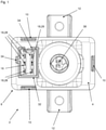
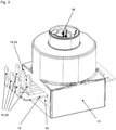
- the pyrotechnic circuit breaker 2 comprises a two-part plastic housing 8 consisting of an upper shell 4 and a lower shell 6, the upper shell 4 and the lower shell 6 being fastened to one another in the final assembly state by means of three snap-on connection elements 10 distributed on the other side.
- the upper shell 4 has two wings 12 which are positioned on two opposite sides of the upper shell 4 in the manner of lateral projections.
- the wings 12 have openings through which screws can be passed for attachment to the holding structure of the motor vehicle.
- a pyrotechnic unit 14 and a current-carrying plate 16 are arranged in the housing 8 of the pyrotechnic circuit breaker 2, with the current-carrying plate 16, as in FIG 3 outlined, the pyrotechnic unit 14 interspersed.
- the individually illustrated current-carrying plate 16 is in this case designed in one piece and in one piece as a stamped and bent plate and has an approximately rectangular basic geometry.
- Six connection elements 18 designed as flat, elongated tongues are positioned on one side of the current-carrying plate 16, which serve as plug-in contacts for a plug-in connection and essentially protrude perpendicularly from the rest of the current-carrying plate 16, that is to say protrude vertically from the plane of the current-carrying plate 16.
- the production of the current-carrying plate 16 takes place in two work steps, with a flat current-carrying plate 16 first being punched out of a sheet-metal strip.
- the tongue-like connection elements 18 are already formed and in a second subsequent processing step the connection elements 18 are then bent out of the plane of the current-carrying plate 16 and bent over until they protrude vertically.
- the current-carrying plate 16 has three retaining lugs 20, which are also designed like tongues and, like the connection elements 18, are bent out of the plane of the current-carrying plate 16 in the second processing step, but only a little.
- connection elements 18 are formed on the central sheet metal strip 22, this serving as an input connection 26 for a power supply via a supply line.
- connection elements 18 are formed on each of the two outer sheet metal strips 22 and are in the form of output connections 28 and are therefore provided for current discharge via a current discharge line.
- the two outer sheet metal strips 22 are also connected to one another via an outlet crosspiece 30 on which another connection element 18 embodied as an outlet connection 28 is formed.
- the pyrotechnic circuit breaker 2 thus has a current input with one plug contact and a current output with five plug contacts.
- the plug contacts, ie the connection elements 18, are arranged in two rows, each with three connection elements 18, and form a plug unit together with a housing wall 32 forming a housing socket.
- a complementary socket unit is plugged into a circuit, so that all six connection elements 18, i.e. both the input connection 26 and the five output connections 28, are connected to corresponding counter-elements of the circuit with just one movement.
- the housing wall 32 is as in 1 and 2 recognizable, designed as a frame-like projection on the top of the upper shell 4, in which the connection elements 18 are countersunk. Furthermore, the housing wall 32 is designed with regard to its geometry in such a way that there are guide elements 34 on two sides, which make it easier to bring the plug unit and socket unit together. In addition, a lateral opening 36 is formed in the housing wall 32, which serves as a functional counterpart to a latching lug on the socket unit, so that the socket unit can be latched on the plug unit.
- the pyrotechnic unit 14 which is not shown in all details, comprises a pyrotechnic propellant charge and an igniter, which is activated by an electrical signal, the trigger or ignition signal, and subsequently ignites the pyrotechnic propellant charge.
- the igniter has a signal input 38 to which a signal transmitter (not shown) can be connected for signals by means of a plug connection.
- the trigger condition for the pyrotechnic circuit breaker 2 is then specified by the signal generator, ie the condition in which the signal generator generates a trigger signal and transmits it to the igniter via the signal input 38, so that the latter ignites the pyrotechnic propellant charge.
- the pyrotechnic unit 14 includes a hammer element 40, called hammer 40 for short, and an anvil element 42, called anvil 42 for short. If the pyrotechnic propellant charge is ignited, it accelerates the hammer element 40 in the direction of the anvil element 42, as a result of which the sheet metal strips 22 positioned between the hammer element 40 and the anvil element 42 are severed in the central region of the current-carrying sheet metal 16.
- the hammer element 40 in the region of the front facing the anvil element 42 has a Web-like or strip-shaped mandrel 44, and on the anvil element 42 there is also a depression 46 adapted to the mandrel 44.
- the mandrel 44 in turn has a material cut-out in the central area, based on the longitudinal extent of the strip shape, or viewed conversely, additional material formations extending in the direction of the anvil element 42 are provided in the outer areas.
- the indentation 46 is also not designed as a simple groove with a uniform profile; instead, additional material recesses are provided at the edge relative to its longitudinal extent.
Landscapes
- Physics & Mathematics (AREA)
- Electromagnetism (AREA)
- Details Of Connecting Devices For Male And Female Coupling (AREA)
Claims (11)
- Commutateur de protection pyrotechnique (2), en particulier pour un véhicule automobile, comprenant un boîtier (8), une tôle de conduction de courant (16) comportant au moins deux éléments de raccordement (18) ainsi qu'une unité pyrotechnique (14) destinée à la désolidarisation d'au moins une partie de la tôle de conduction de courant (16), l'un desdits au moins deux éléments de raccordement (18) de la tôle de conduction de courant (16) étant configuré sous forme de borne d'entrée (26) pour une ligne d'arrivée de courant et l'autre desdits au moins deux éléments de raccordement (18) étant configuré sous forme de borne de sortie (28) pour une ligne de départ de courant,
caractérisé en ce que
tous les éléments de raccordement (18) de la tôle de conduction de courant (16) sont configurés sous forme de contacts à fiches d'un connecteur et tous les éléments de raccordement (18) aussi bien de la borne d'entrée (26) que de la borne de sortie (28) sont disposés d'un côté dans une zone de bord de la tôle de conduction de courant (16) et constituent une unité enfichable et en ce que la tôle de conduction de courant (16) comporte au moins deux bandes de tôle (22) qui sont orientées essentiellement parallèlement entre elles dans la zone d'action de l'unité pyrotechnique (14), l'une desdites au moins deux bandes de tôle (22) étant reliée en conduction électrique, en tant que partie d'un trajet de courant d'entrée, à la borne d'entrée (26) et l'autre desdites au moins deux bandes de tôle (22) étant reliée en conduction électrique, en tant que partie d'un trajet de courant de sortie, à la borne de sortie (28), les bandes de tôle (22) étant raccordées l'une à l'autre à l'extérieur de la zone d'action de l'unité pyrotechnique,
l'unité pyrotechnique (14) comprenant un élément de type marteau (40) qui, dans le cas de déclenchement, est projeté sur un élément de type enclume (42), et l'élément de type marteau (40) étant conçu de telle façon que les deux bandes de tôle (22) sont, dans le cas de déclenchement, frappées par l'élément de type marteau (40) et dissociées. - Commutateur de protection pyrotechnique (2) selon la revendication 1,
caractérisé en ce que
la tôle de conduction de courant (16) comportant les éléments de raccordement (18) est réalisée sous forme d'une tôle estampée et pliée en une seule pièce. - Commutateur de protection pyrotechnique (2) selon la revendication 1 ou 2,
caractérisé en ce que
la borne d'entrée (26) et la borne de sortie (28) sont reliées l'une à l'autre par un élément connecteur transversal (24) de la tôle de conduction de courant (16), qui est disposé dans une deuxième zone de bord de la tôle de conduction de courant (16) en faisant face à la borne d'entrée (26) et à la borne de sortie (28). - Commutateur de protection pyrotechnique (2) selon l'une quelconque des revendications 1 à 3,
caractérisé en ce que
les éléments de raccordement (18) de la tôle de conduction de courant (16) sont en disposition de type matrice. - Commutateur de protection pyrotechnique (2) selon l'une quelconque des revendications 1 à 4
caractérisé en ce que
les éléments de raccordement (18) de la tôle de conduction de courant (16) sont réalisés sous forme de lames repliées de la tôle de conduction de courant (16). - Commutateur de protection pyrotechnique (2) selon l'une quelconque des revendications 1 à 5,
caractérisé en ce que
la tôle de conduction de courant (16) comporte des éléments de raccordement (18) faisant saillie. - Commutateur de protection pyrotechnique (2) selon l'une quelconque des revendications 1 à 6,
caractérisé en ce que
la tôle de conduction de courant (16) comporte des éléments de raccordement (18) faisant saillie essentiellement verticalement. - Commutateur de protection pyrotechnique (2) selon l'une quelconque des revendications 1 à 7,
caractérisé en ce que
tous les éléments de raccordement (18) de la tôle de conduction de courant (16) sont entourés par une paroi de boîtier (32) du boîtier (8). - Commutateur de protection pyrotechnique (2) selon la revendication 8,
caractérisé en ce que
la paroi de boîtier (32) constitue une douille de boîtier dans laquelle sont disposés tous les éléments de raccordement (18) de la tôle de conduction de courant (16). - Commutateur de protection pyrotechnique (2) selon l'une quelconque des revendications 1 à 9,
caractérisé en ce
qu'un point destiné à la rupture (48) est réalisé sur la tôle de conduction de courant (16). - Commutateur de protection pyrotechnique (2) selon l'une quelconque des revendications 1 à 10,
caractérisé en ce que
ce dernier en tant que composant de montage préfabriqué à tôle de conduction de courant (16) intégrée et unité pyrotechnique (14) intégrée est conçu de telle façon que l'unité de montage est raccordée électriquement exclusivement à l'aide des contacts à fiches dans un circuit de commutation et en particulier dans un réseau de bord d'un véhicule automobile.
Applications Claiming Priority (2)
| Application Number | Priority Date | Filing Date | Title |
|---|---|---|---|
| DE102014222230.3A DE102014222230A1 (de) | 2014-10-30 | 2014-10-30 | Pyrotechnischer Schutzschalter |
| PCT/EP2015/075025 WO2016066707A1 (fr) | 2014-10-30 | 2015-10-28 | Disjoncteur de protection pyrotechnique |
Publications (2)
| Publication Number | Publication Date |
|---|---|
| EP3213336A1 EP3213336A1 (fr) | 2017-09-06 |
| EP3213336B1 true EP3213336B1 (fr) | 2022-03-02 |
Family
ID=54703928
Family Applications (1)
| Application Number | Title | Priority Date | Filing Date |
|---|---|---|---|
| EP15800726.0A Not-in-force EP3213336B1 (fr) | 2014-10-30 | 2015-10-28 | Disjoncteur de protection pyrotechnique |
Country Status (3)
| Country | Link |
|---|---|
| EP (1) | EP3213336B1 (fr) |
| DE (1) | DE102014222230A1 (fr) |
| WO (1) | WO2016066707A1 (fr) |
Families Citing this family (1)
| Publication number | Priority date | Publication date | Assignee | Title |
|---|---|---|---|---|
| DE102017207735B3 (de) | 2017-05-08 | 2018-08-23 | Leoni Bordnetz-Systeme Gmbh | Pyrotechnischer Trennschalter |
Citations (1)
| Publication number | Priority date | Publication date | Assignee | Title |
|---|---|---|---|---|
| US3909767A (en) * | 1974-01-14 | 1975-09-30 | Littelfuse Inc | Miniature plug-in fuse |
Family Cites Families (10)
| Publication number | Priority date | Publication date | Assignee | Title |
|---|---|---|---|---|
| DE3931188A1 (de) * | 1989-09-19 | 1991-03-28 | Baer Elektrowerke Gmbh & Co Kg | Schalterkombination |
| DE19616994A1 (de) * | 1996-04-27 | 1997-10-30 | Dynamit Nobel Ag | Pyrotechnisches Sicherungselement für Stromkreise |
| DE19749896A1 (de) * | 1997-11-12 | 1999-06-02 | Knipping Kunststofftechnik Wer | Pyrotechnischer Sicherheitsschalter |
| DE29917468U1 (de) * | 1999-10-04 | 1999-12-16 | Lisa Dräxlmaier GmbH, 84137 Vilsbiburg | Relais-Modul |
| DE102004008120A1 (de) * | 2003-02-26 | 2004-11-25 | Dynamit Nobel Ais Gmbh Automotive Ignition Systems | Pyromechanische Trennvorrichtung mit speziell geformter Stromleiterschiene |
| US7498531B2 (en) * | 2003-03-12 | 2009-03-03 | Delphi Technologies, Inc. | Housing and a conducting rail for disconnecting a battery |
| JP4412147B2 (ja) * | 2004-10-21 | 2010-02-10 | アンデン株式会社 | 電気部品装置 |
| JP5166879B2 (ja) * | 2005-11-25 | 2013-03-21 | 株式会社オートネットワーク技術研究所 | ジョイント部品およびこれを用いたワイヤーハーネス |
| DE102009025425B4 (de) * | 2009-06-16 | 2012-02-02 | Autokabel-Managementgesellschaft Mbh | Elektrische Trennvorrichtung sowie Fahrzeug damit |
| JP5817685B2 (ja) * | 2012-08-31 | 2015-11-18 | 豊田合成株式会社 | 導通遮断装置 |
-
2014
- 2014-10-30 DE DE102014222230.3A patent/DE102014222230A1/de not_active Ceased
-
2015
- 2015-10-28 WO PCT/EP2015/075025 patent/WO2016066707A1/fr not_active Ceased
- 2015-10-28 EP EP15800726.0A patent/EP3213336B1/fr not_active Not-in-force
Patent Citations (1)
| Publication number | Priority date | Publication date | Assignee | Title |
|---|---|---|---|---|
| US3909767A (en) * | 1974-01-14 | 1975-09-30 | Littelfuse Inc | Miniature plug-in fuse |
Also Published As
| Publication number | Publication date |
|---|---|
| DE102014222230A1 (de) | 2016-05-04 |
| WO2016066707A1 (fr) | 2016-05-06 |
| EP3213336A1 (fr) | 2017-09-06 |
Similar Documents
| Publication | Publication Date | Title |
|---|---|---|
| DE102016116781B4 (de) | Leitungsunterbrechungsvorrichtung | |
| DE102012221664B4 (de) | Kurzschlussabschalter | |
| EP2545575A1 (fr) | Coupe-circuit à fusible pour conduite d'alimentation en énergie de véhicule à moteur | |
| DE102011014343A1 (de) | Sicherungsvorrichtung für eine Spannungsversorgung eines Kraftfahrzeugs | |
| EP3525223B1 (fr) | Commutateur pyrotechnique | |
| DE102017207736B3 (de) | Pyrotechnischer Schutzschalter und Versorgungsnetz mit einem pyrotechnischen Schutzschalter | |
| DE102016109428B4 (de) | Leitungstrennvorrichtung | |
| EP1469564A1 (fr) | Borne de batterie pyrotechnique | |
| EP2020013A1 (fr) | Procédé et dispositif pour la séparation unique et durable d'une liaison électrique, en particulier dans un véhicule automobile | |
| EP3622549B1 (fr) | Disjoncteur pyrotechnique et réseau d'alimentation équipé d'un disjoncteur pyrotechnique | |
| EP3251141B1 (fr) | Élément de sécurité pyrotechnique | |
| DE102016216829A1 (de) | Trenneinrichtung zum Trennen einer elektrischen Verbindung zwischen zwei Komponenten eines Kraftfahrzeugs, sowie Vorrichtung mit einer solchen Trenneinrichtung | |
| DE102015225521B4 (de) | Vorrichtung zum Schalten eines elektrischen Stromkreises, Fahrzeug mit einer solchen Vorrichtung sowie ein Verfahren zu deren Betrieb | |
| EP3213336B1 (fr) | Disjoncteur de protection pyrotechnique | |
| DE10209626B4 (de) | Pyrotechnischer Schalter | |
| DE112018004650B4 (de) | Elektrische Schutzschaltervorrichtung | |
| EP3192093B1 (fr) | Arrangement fusible a multiple borne | |
| DE102008013831B4 (de) | Trennvorrichtung zum Trennen von zumindest zwei elektrischen Stromkreisen sowie Kraftfahrzeug mit dieser | |
| EP3618089B1 (fr) | Sectionneur de courant pyrotechnique | |
| AT526923B1 (de) | Pyrotechnischer Stromtrenner | |
| DE102017217520A1 (de) | Sicherheitsanordnung für eine elektrische Komponente eines Kraftfahrzeugs und Kraftfahrzeug mit einer solchen Sicherheitsanordnung | |
| DE102017207735B3 (de) | Pyrotechnischer Trennschalter | |
| DE102020112918B4 (de) | Elektrische Trennvorrichtung, System mit einer Trennvorrichtung sowie Verfahren zur Herstellung einer Trennvorrichtung | |
| DE10337980A1 (de) | Pyromechanisches Batteriepol-Trennelement | |
| DE102014108245A1 (de) | Sicherheitsvorrichtung zur Unterbrechung einer Hochvoltleitung für ein Kraftfahrzeug |
Legal Events
| Date | Code | Title | Description |
|---|---|---|---|
| STAA | Information on the status of an ep patent application or granted ep patent |
Free format text: STATUS: THE INTERNATIONAL PUBLICATION HAS BEEN MADE |
|
| PUAI | Public reference made under article 153(3) epc to a published international application that has entered the european phase |
Free format text: ORIGINAL CODE: 0009012 |
|
| STAA | Information on the status of an ep patent application or granted ep patent |
Free format text: STATUS: REQUEST FOR EXAMINATION WAS MADE |
|
| 17P | Request for examination filed |
Effective date: 20170407 |
|
| AK | Designated contracting states |
Kind code of ref document: A1 Designated state(s): AL AT BE BG CH CY CZ DE DK EE ES FI FR GB GR HR HU IE IS IT LI LT LU LV MC MK MT NL NO PL PT RO RS SE SI SK SM TR |
|
| AX | Request for extension of the european patent |
Extension state: BA ME |
|
| DAV | Request for validation of the european patent (deleted) | ||
| DAX | Request for extension of the european patent (deleted) | ||
| STAA | Information on the status of an ep patent application or granted ep patent |
Free format text: STATUS: EXAMINATION IS IN PROGRESS |
|
| 17Q | First examination report despatched |
Effective date: 20191113 |
|
| GRAP | Despatch of communication of intention to grant a patent |
Free format text: ORIGINAL CODE: EPIDOSNIGR1 |
|
| STAA | Information on the status of an ep patent application or granted ep patent |
Free format text: STATUS: GRANT OF PATENT IS INTENDED |
|
| INTG | Intention to grant announced |
Effective date: 20211214 |
|
| GRAS | Grant fee paid |
Free format text: ORIGINAL CODE: EPIDOSNIGR3 |
|
| GRAA | (expected) grant |
Free format text: ORIGINAL CODE: 0009210 |
|
| STAA | Information on the status of an ep patent application or granted ep patent |
Free format text: STATUS: THE PATENT HAS BEEN GRANTED |
|
| AK | Designated contracting states |
Kind code of ref document: B1 Designated state(s): AL AT BE BG CH CY CZ DE DK EE ES FI FR GB GR HR HU IE IS IT LI LT LU LV MC MK MT NL NO PL PT RO RS SE SI SK SM TR |
|
| REG | Reference to a national code |
Ref country code: GB Ref legal event code: FG4D Free format text: NOT ENGLISH |
|
| RIN1 | Information on inventor provided before grant (corrected) |
Inventor name: WOLF, SASCHA Inventor name: WAGNER, GUNNAR Inventor name: STEINER, PETER Inventor name: HOPF, MARTIN |
|
| REG | Reference to a national code |
Ref country code: CH Ref legal event code: EP Ref country code: AT Ref legal event code: REF Ref document number: 1472928 Country of ref document: AT Kind code of ref document: T Effective date: 20220315 |
|
| REG | Reference to a national code |
Ref country code: DE Ref legal event code: R096 Ref document number: 502015015684 Country of ref document: DE |
|
| REG | Reference to a national code |
Ref country code: IE Ref legal event code: FG4D Free format text: LANGUAGE OF EP DOCUMENT: GERMAN |
|
| REG | Reference to a national code |
Ref country code: LT Ref legal event code: MG9D |
|
| REG | Reference to a national code |
Ref country code: NL Ref legal event code: MP Effective date: 20220302 |
|
| PG25 | Lapsed in a contracting state [announced via postgrant information from national office to epo] |
Ref country code: SE Free format text: LAPSE BECAUSE OF FAILURE TO SUBMIT A TRANSLATION OF THE DESCRIPTION OR TO PAY THE FEE WITHIN THE PRESCRIBED TIME-LIMIT Effective date: 20220302 Ref country code: RS Free format text: LAPSE BECAUSE OF FAILURE TO SUBMIT A TRANSLATION OF THE DESCRIPTION OR TO PAY THE FEE WITHIN THE PRESCRIBED TIME-LIMIT Effective date: 20220302 Ref country code: NO Free format text: LAPSE BECAUSE OF FAILURE TO SUBMIT A TRANSLATION OF THE DESCRIPTION OR TO PAY THE FEE WITHIN THE PRESCRIBED TIME-LIMIT Effective date: 20220602 Ref country code: LT Free format text: LAPSE BECAUSE OF FAILURE TO SUBMIT A TRANSLATION OF THE DESCRIPTION OR TO PAY THE FEE WITHIN THE PRESCRIBED TIME-LIMIT Effective date: 20220302 Ref country code: HR Free format text: LAPSE BECAUSE OF FAILURE TO SUBMIT A TRANSLATION OF THE DESCRIPTION OR TO PAY THE FEE WITHIN THE PRESCRIBED TIME-LIMIT Effective date: 20220302 Ref country code: ES Free format text: LAPSE BECAUSE OF FAILURE TO SUBMIT A TRANSLATION OF THE DESCRIPTION OR TO PAY THE FEE WITHIN THE PRESCRIBED TIME-LIMIT Effective date: 20220302 Ref country code: BG Free format text: LAPSE BECAUSE OF FAILURE TO SUBMIT A TRANSLATION OF THE DESCRIPTION OR TO PAY THE FEE WITHIN THE PRESCRIBED TIME-LIMIT Effective date: 20220602 |
|
| PG25 | Lapsed in a contracting state [announced via postgrant information from national office to epo] |
Ref country code: PL Free format text: LAPSE BECAUSE OF FAILURE TO SUBMIT A TRANSLATION OF THE DESCRIPTION OR TO PAY THE FEE WITHIN THE PRESCRIBED TIME-LIMIT Effective date: 20220302 Ref country code: LV Free format text: LAPSE BECAUSE OF FAILURE TO SUBMIT A TRANSLATION OF THE DESCRIPTION OR TO PAY THE FEE WITHIN THE PRESCRIBED TIME-LIMIT Effective date: 20220302 Ref country code: GR Free format text: LAPSE BECAUSE OF FAILURE TO SUBMIT A TRANSLATION OF THE DESCRIPTION OR TO PAY THE FEE WITHIN THE PRESCRIBED TIME-LIMIT Effective date: 20220603 Ref country code: FI Free format text: LAPSE BECAUSE OF FAILURE TO SUBMIT A TRANSLATION OF THE DESCRIPTION OR TO PAY THE FEE WITHIN THE PRESCRIBED TIME-LIMIT Effective date: 20220302 |
|
| PG25 | Lapsed in a contracting state [announced via postgrant information from national office to epo] |
Ref country code: NL Free format text: LAPSE BECAUSE OF FAILURE TO SUBMIT A TRANSLATION OF THE DESCRIPTION OR TO PAY THE FEE WITHIN THE PRESCRIBED TIME-LIMIT Effective date: 20220302 |
|
| PG25 | Lapsed in a contracting state [announced via postgrant information from national office to epo] |
Ref country code: SM Free format text: LAPSE BECAUSE OF FAILURE TO SUBMIT A TRANSLATION OF THE DESCRIPTION OR TO PAY THE FEE WITHIN THE PRESCRIBED TIME-LIMIT Effective date: 20220302 Ref country code: SK Free format text: LAPSE BECAUSE OF FAILURE TO SUBMIT A TRANSLATION OF THE DESCRIPTION OR TO PAY THE FEE WITHIN THE PRESCRIBED TIME-LIMIT Effective date: 20220302 Ref country code: RO Free format text: LAPSE BECAUSE OF FAILURE TO SUBMIT A TRANSLATION OF THE DESCRIPTION OR TO PAY THE FEE WITHIN THE PRESCRIBED TIME-LIMIT Effective date: 20220302 Ref country code: PT Free format text: LAPSE BECAUSE OF FAILURE TO SUBMIT A TRANSLATION OF THE DESCRIPTION OR TO PAY THE FEE WITHIN THE PRESCRIBED TIME-LIMIT Effective date: 20220704 Ref country code: EE Free format text: LAPSE BECAUSE OF FAILURE TO SUBMIT A TRANSLATION OF THE DESCRIPTION OR TO PAY THE FEE WITHIN THE PRESCRIBED TIME-LIMIT Effective date: 20220302 Ref country code: CZ Free format text: LAPSE BECAUSE OF FAILURE TO SUBMIT A TRANSLATION OF THE DESCRIPTION OR TO PAY THE FEE WITHIN THE PRESCRIBED TIME-LIMIT Effective date: 20220302 |
|
| PG25 | Lapsed in a contracting state [announced via postgrant information from national office to epo] |
Ref country code: IS Free format text: LAPSE BECAUSE OF FAILURE TO SUBMIT A TRANSLATION OF THE DESCRIPTION OR TO PAY THE FEE WITHIN THE PRESCRIBED TIME-LIMIT Effective date: 20220702 Ref country code: AL Free format text: LAPSE BECAUSE OF FAILURE TO SUBMIT A TRANSLATION OF THE DESCRIPTION OR TO PAY THE FEE WITHIN THE PRESCRIBED TIME-LIMIT Effective date: 20220302 |
|
| REG | Reference to a national code |
Ref country code: DE Ref legal event code: R097 Ref document number: 502015015684 Country of ref document: DE |
|
| PGFP | Annual fee paid to national office [announced via postgrant information from national office to epo] |
Ref country code: FR Payment date: 20221020 Year of fee payment: 8 |
|
| PLBE | No opposition filed within time limit |
Free format text: ORIGINAL CODE: 0009261 |
|
| STAA | Information on the status of an ep patent application or granted ep patent |
Free format text: STATUS: NO OPPOSITION FILED WITHIN TIME LIMIT |
|
| PG25 | Lapsed in a contracting state [announced via postgrant information from national office to epo] |
Ref country code: DK Free format text: LAPSE BECAUSE OF FAILURE TO SUBMIT A TRANSLATION OF THE DESCRIPTION OR TO PAY THE FEE WITHIN THE PRESCRIBED TIME-LIMIT Effective date: 20220302 |
|
| PGFP | Annual fee paid to national office [announced via postgrant information from national office to epo] |
Ref country code: GB Payment date: 20221024 Year of fee payment: 8 Ref country code: DE Payment date: 20221020 Year of fee payment: 8 |
|
| 26N | No opposition filed |
Effective date: 20221205 |
|
| PG25 | Lapsed in a contracting state [announced via postgrant information from national office to epo] |
Ref country code: SI Free format text: LAPSE BECAUSE OF FAILURE TO SUBMIT A TRANSLATION OF THE DESCRIPTION OR TO PAY THE FEE WITHIN THE PRESCRIBED TIME-LIMIT Effective date: 20220302 |
|
| PG25 | Lapsed in a contracting state [announced via postgrant information from national office to epo] |
Ref country code: MC Free format text: LAPSE BECAUSE OF FAILURE TO SUBMIT A TRANSLATION OF THE DESCRIPTION OR TO PAY THE FEE WITHIN THE PRESCRIBED TIME-LIMIT Effective date: 20220302 |
|
| REG | Reference to a national code |
Ref country code: CH Ref legal event code: PL |
|
| REG | Reference to a national code |
Ref country code: BE Ref legal event code: MM Effective date: 20221031 |
|
| PG25 | Lapsed in a contracting state [announced via postgrant information from national office to epo] |
Ref country code: LU Free format text: LAPSE BECAUSE OF NON-PAYMENT OF DUE FEES Effective date: 20221028 |
|
| P01 | Opt-out of the competence of the unified patent court (upc) registered |
Effective date: 20230527 |
|
| PG25 | Lapsed in a contracting state [announced via postgrant information from national office to epo] |
Ref country code: LI Free format text: LAPSE BECAUSE OF NON-PAYMENT OF DUE FEES Effective date: 20221031 Ref country code: IT Free format text: LAPSE BECAUSE OF FAILURE TO SUBMIT A TRANSLATION OF THE DESCRIPTION OR TO PAY THE FEE WITHIN THE PRESCRIBED TIME-LIMIT Effective date: 20220302 Ref country code: CH Free format text: LAPSE BECAUSE OF NON-PAYMENT OF DUE FEES Effective date: 20221031 |
|
| PG25 | Lapsed in a contracting state [announced via postgrant information from national office to epo] |
Ref country code: BE Free format text: LAPSE BECAUSE OF NON-PAYMENT OF DUE FEES Effective date: 20221031 |
|
| PG25 | Lapsed in a contracting state [announced via postgrant information from national office to epo] |
Ref country code: IE Free format text: LAPSE BECAUSE OF NON-PAYMENT OF DUE FEES Effective date: 20221028 |
|
| REG | Reference to a national code |
Ref country code: AT Ref legal event code: MM01 Ref document number: 1472928 Country of ref document: AT Kind code of ref document: T Effective date: 20221028 |
|
| PG25 | Lapsed in a contracting state [announced via postgrant information from national office to epo] |
Ref country code: AT Free format text: LAPSE BECAUSE OF NON-PAYMENT OF DUE FEES Effective date: 20221028 |
|
| PG25 | Lapsed in a contracting state [announced via postgrant information from national office to epo] |
Ref country code: HU Free format text: LAPSE BECAUSE OF FAILURE TO SUBMIT A TRANSLATION OF THE DESCRIPTION OR TO PAY THE FEE WITHIN THE PRESCRIBED TIME-LIMIT; INVALID AB INITIO Effective date: 20151028 |
|
| PG25 | Lapsed in a contracting state [announced via postgrant information from national office to epo] |
Ref country code: CY Free format text: LAPSE BECAUSE OF FAILURE TO SUBMIT A TRANSLATION OF THE DESCRIPTION OR TO PAY THE FEE WITHIN THE PRESCRIBED TIME-LIMIT Effective date: 20220302 |
|
| REG | Reference to a national code |
Ref country code: DE Ref legal event code: R119 Ref document number: 502015015684 Country of ref document: DE |
|
| PG25 | Lapsed in a contracting state [announced via postgrant information from national office to epo] |
Ref country code: MK Free format text: LAPSE BECAUSE OF FAILURE TO SUBMIT A TRANSLATION OF THE DESCRIPTION OR TO PAY THE FEE WITHIN THE PRESCRIBED TIME-LIMIT Effective date: 20220302 |
|
| GBPC | Gb: european patent ceased through non-payment of renewal fee |
Effective date: 20231028 |
|
| PG25 | Lapsed in a contracting state [announced via postgrant information from national office to epo] |
Ref country code: TR Free format text: LAPSE BECAUSE OF FAILURE TO SUBMIT A TRANSLATION OF THE DESCRIPTION OR TO PAY THE FEE WITHIN THE PRESCRIBED TIME-LIMIT Effective date: 20220302 |
|
| PG25 | Lapsed in a contracting state [announced via postgrant information from national office to epo] |
Ref country code: GB Free format text: LAPSE BECAUSE OF NON-PAYMENT OF DUE FEES Effective date: 20231028 |
|
| PG25 | Lapsed in a contracting state [announced via postgrant information from national office to epo] |
Ref country code: GB Free format text: LAPSE BECAUSE OF NON-PAYMENT OF DUE FEES Effective date: 20231028 Ref country code: FR Free format text: LAPSE BECAUSE OF NON-PAYMENT OF DUE FEES Effective date: 20231031 Ref country code: DE Free format text: LAPSE BECAUSE OF NON-PAYMENT OF DUE FEES Effective date: 20240501 |
|
| PG25 | Lapsed in a contracting state [announced via postgrant information from national office to epo] |
Ref country code: MT Free format text: LAPSE BECAUSE OF FAILURE TO SUBMIT A TRANSLATION OF THE DESCRIPTION OR TO PAY THE FEE WITHIN THE PRESCRIBED TIME-LIMIT Effective date: 20220302 |