EP3213496B1 - Cible translatable d'étalonnage de scanner - Google Patents
Cible translatable d'étalonnage de scanner Download PDFInfo
- Publication number
- EP3213496B1 EP3213496B1 EP14904652.6A EP14904652A EP3213496B1 EP 3213496 B1 EP3213496 B1 EP 3213496B1 EP 14904652 A EP14904652 A EP 14904652A EP 3213496 B1 EP3213496 B1 EP 3213496B1
- Authority
- EP
- European Patent Office
- Prior art keywords
- scanner
- calibration
- calibration target
- bias plate
- document
- Prior art date
- Legal status (The legal status is an assumption and is not a legal conclusion. Google has not performed a legal analysis and makes no representation as to the accuracy of the status listed.)
- Active
Links
Images



Classifications
-
- H—ELECTRICITY
- H04—ELECTRIC COMMUNICATION TECHNIQUE
- H04N—PICTORIAL COMMUNICATION, e.g. TELEVISION
- H04N1/00—Scanning, transmission or reproduction of documents or the like, e.g. facsimile transmission; Details thereof
- H04N1/00795—Reading arrangements
- H04N1/00798—Circuits or arrangements for the control thereof, e.g. using a programmed control device or according to a measured quantity
- H04N1/00819—Self-calibrating reading means
-
- H—ELECTRICITY
- H04—ELECTRIC COMMUNICATION TECHNIQUE
- H04N—PICTORIAL COMMUNICATION, e.g. TELEVISION
- H04N1/00—Scanning, transmission or reproduction of documents or the like, e.g. facsimile transmission; Details thereof
- H04N1/00002—Diagnosis, testing or measuring; Detecting, analysing or monitoring not otherwise provided for
- H04N1/00007—Diagnosis, testing or measuring; Detecting, analysing or monitoring not otherwise provided for relating to particular apparatus or devices
- H04N1/00018—Scanning arrangements
-
- H—ELECTRICITY
- H04—ELECTRIC COMMUNICATION TECHNIQUE
- H04N—PICTORIAL COMMUNICATION, e.g. TELEVISION
- H04N1/00—Scanning, transmission or reproduction of documents or the like, e.g. facsimile transmission; Details thereof
- H04N1/00002—Diagnosis, testing or measuring; Detecting, analysing or monitoring not otherwise provided for
- H04N1/00026—Methods therefor
- H04N1/00029—Diagnosis, i.e. identifying a problem by comparison with a normal state
-
- H—ELECTRICITY
- H04—ELECTRIC COMMUNICATION TECHNIQUE
- H04N—PICTORIAL COMMUNICATION, e.g. TELEVISION
- H04N1/00—Scanning, transmission or reproduction of documents or the like, e.g. facsimile transmission; Details thereof
- H04N1/00002—Diagnosis, testing or measuring; Detecting, analysing or monitoring not otherwise provided for
- H04N1/00026—Methods therefor
- H04N1/00045—Methods therefor using a reference pattern designed for the purpose, e.g. a test chart
-
- H—ELECTRICITY
- H04—ELECTRIC COMMUNICATION TECHNIQUE
- H04N—PICTORIAL COMMUNICATION, e.g. TELEVISION
- H04N1/00—Scanning, transmission or reproduction of documents or the like, e.g. facsimile transmission; Details thereof
- H04N1/00002—Diagnosis, testing or measuring; Detecting, analysing or monitoring not otherwise provided for
- H04N1/00071—Diagnosis, testing or measuring; Detecting, analysing or monitoring not otherwise provided for characterised by the action taken
- H04N1/00082—Adjusting or controlling
-
- H—ELECTRICITY
- H04—ELECTRIC COMMUNICATION TECHNIQUE
- H04N—PICTORIAL COMMUNICATION, e.g. TELEVISION
- H04N1/00—Scanning, transmission or reproduction of documents or the like, e.g. facsimile transmission; Details thereof
- H04N1/00002—Diagnosis, testing or measuring; Detecting, analysing or monitoring not otherwise provided for
- H04N1/00071—Diagnosis, testing or measuring; Detecting, analysing or monitoring not otherwise provided for characterised by the action taken
- H04N1/00082—Adjusting or controlling
- H04N1/00087—Setting or calibrating
-
- H—ELECTRICITY
- H04—ELECTRIC COMMUNICATION TECHNIQUE
- H04N—PICTORIAL COMMUNICATION, e.g. TELEVISION
- H04N1/00—Scanning, transmission or reproduction of documents or the like, e.g. facsimile transmission; Details thereof
- H04N1/024—Details of scanning heads ; Means for illuminating the original
- H04N1/028—Details of scanning heads ; Means for illuminating the original for picture information pick-up
-
- H—ELECTRICITY
- H04—ELECTRIC COMMUNICATION TECHNIQUE
- H04N—PICTORIAL COMMUNICATION, e.g. TELEVISION
- H04N1/00—Scanning, transmission or reproduction of documents or the like, e.g. facsimile transmission; Details thereof
- H04N1/024—Details of scanning heads ; Means for illuminating the original
- H04N1/028—Details of scanning heads ; Means for illuminating the original for picture information pick-up
- H04N1/03—Details of scanning heads ; Means for illuminating the original for picture information pick-up with photodetectors arranged in a substantially linear array
- H04N1/031—Details of scanning heads ; Means for illuminating the original for picture information pick-up with photodetectors arranged in a substantially linear array the photodetectors having a one-to-one and optically positive correspondence with the scanned picture elements, e.g. linear contact sensors
- H04N1/0311—Details of scanning heads ; Means for illuminating the original for picture information pick-up with photodetectors arranged in a substantially linear array the photodetectors having a one-to-one and optically positive correspondence with the scanned picture elements, e.g. linear contact sensors using an array of elements to project the scanned image elements onto the photodetectors
- H04N1/0312—Details of scanning heads ; Means for illuminating the original for picture information pick-up with photodetectors arranged in a substantially linear array the photodetectors having a one-to-one and optically positive correspondence with the scanned picture elements, e.g. linear contact sensors using an array of elements to project the scanned image elements onto the photodetectors using an array of optical fibres or rod-lenses
-
- H—ELECTRICITY
- H04—ELECTRIC COMMUNICATION TECHNIQUE
- H04N—PICTORIAL COMMUNICATION, e.g. TELEVISION
- H04N1/00—Scanning, transmission or reproduction of documents or the like, e.g. facsimile transmission; Details thereof
- H04N1/04—Scanning arrangements, i.e. arrangements for the displacement of active reading or reproducing elements relative to the original or reproducing medium, or vice versa
-
- H—ELECTRICITY
- H04—ELECTRIC COMMUNICATION TECHNIQUE
- H04N—PICTORIAL COMMUNICATION, e.g. TELEVISION
- H04N1/00—Scanning, transmission or reproduction of documents or the like, e.g. facsimile transmission; Details thereof
- H04N1/04—Scanning arrangements, i.e. arrangements for the displacement of active reading or reproducing elements relative to the original or reproducing medium, or vice versa
- H04N1/10—Scanning arrangements, i.e. arrangements for the displacement of active reading or reproducing elements relative to the original or reproducing medium, or vice versa using flat picture-bearing surfaces
- H04N1/1013—Scanning arrangements, i.e. arrangements for the displacement of active reading or reproducing elements relative to the original or reproducing medium, or vice versa using flat picture-bearing surfaces with sub-scanning by translatory movement of at least a part of the main-scanning components
- H04N1/1017—Scanning arrangements, i.e. arrangements for the displacement of active reading or reproducing elements relative to the original or reproducing medium, or vice versa using flat picture-bearing surfaces with sub-scanning by translatory movement of at least a part of the main-scanning components the main-scanning components remaining positionally invariant with respect to one another in the sub-scanning direction
-
- H—ELECTRICITY
- H04—ELECTRIC COMMUNICATION TECHNIQUE
- H04N—PICTORIAL COMMUNICATION, e.g. TELEVISION
- H04N1/00—Scanning, transmission or reproduction of documents or the like, e.g. facsimile transmission; Details thereof
- H04N1/04—Scanning arrangements, i.e. arrangements for the displacement of active reading or reproducing elements relative to the original or reproducing medium, or vice versa
- H04N1/12—Scanning arrangements, i.e. arrangements for the displacement of active reading or reproducing elements relative to the original or reproducing medium, or vice versa using the sheet-feed movement or the medium-advance or the drum-rotation movement as the slow scanning component, e.g. arrangements for the main-scanning
- H04N1/121—Feeding arrangements
- H04N1/1225—Means for maintaining contact between the sheet and the image sensor, e.g. pressing means
-
- H—ELECTRICITY
- H04—ELECTRIC COMMUNICATION TECHNIQUE
- H04N—PICTORIAL COMMUNICATION, e.g. TELEVISION
- H04N1/00—Scanning, transmission or reproduction of documents or the like, e.g. facsimile transmission; Details thereof
- H04N1/40—Picture signal circuits
- H04N1/409—Edge or detail enhancement; Noise or error suppression
- H04N1/4097—Removing errors due external factors, e.g. dust, scratches
-
- H—ELECTRICITY
- H04—ELECTRIC COMMUNICATION TECHNIQUE
- H04N—PICTORIAL COMMUNICATION, e.g. TELEVISION
- H04N25/00—Circuitry of solid-state image sensors [SSIS]; Control thereof
- H04N25/60—Noise processing, e.g. detecting, correcting, reducing or removing noise
- H04N25/68—Noise processing, e.g. detecting, correcting, reducing or removing noise applied to defects
-
- H—ELECTRICITY
- H04—ELECTRIC COMMUNICATION TECHNIQUE
- H04N—PICTORIAL COMMUNICATION, e.g. TELEVISION
- H04N1/00—Scanning, transmission or reproduction of documents or the like, e.g. facsimile transmission; Details thereof
- H04N1/024—Details of scanning heads ; Means for illuminating the original
- H04N1/028—Details of scanning heads ; Means for illuminating the original for picture information pick-up
- H04N1/03—Details of scanning heads ; Means for illuminating the original for picture information pick-up with photodetectors arranged in a substantially linear array
-
- H—ELECTRICITY
- H04—ELECTRIC COMMUNICATION TECHNIQUE
- H04N—PICTORIAL COMMUNICATION, e.g. TELEVISION
- H04N2201/00—Indexing scheme relating to scanning, transmission or reproduction of documents or the like, and to details thereof
- H04N2201/0077—Types of the still picture apparatus
- H04N2201/0081—Image reader
-
- H—ELECTRICITY
- H04—ELECTRIC COMMUNICATION TECHNIQUE
- H04N—PICTORIAL COMMUNICATION, e.g. TELEVISION
- H04N2201/00—Indexing scheme relating to scanning, transmission or reproduction of documents or the like, and to details thereof
- H04N2201/024—Indexing scheme relating to scanning, transmission or reproduction of documents or the like, and to details thereof deleted
- H04N2201/02497—Additional elements, e.g. sheet guide plates, light shields
-
- H—ELECTRICITY
- H04—ELECTRIC COMMUNICATION TECHNIQUE
- H04N—PICTORIAL COMMUNICATION, e.g. TELEVISION
- H04N2201/00—Indexing scheme relating to scanning, transmission or reproduction of documents or the like, and to details thereof
- H04N2201/04—Scanning arrangements
- H04N2201/0402—Arrangements not specific to a particular one of the scanning methods covered by groups H04N1/04 - H04N1/207
- H04N2201/0404—Scanning transparent media, e.g. photographic film
-
- H—ELECTRICITY
- H04—ELECTRIC COMMUNICATION TECHNIQUE
- H04N—PICTORIAL COMMUNICATION, e.g. TELEVISION
- H04N2201/00—Indexing scheme relating to scanning, transmission or reproduction of documents or the like, and to details thereof
- H04N2201/04—Scanning arrangements
- H04N2201/0402—Arrangements not specific to a particular one of the scanning methods covered by groups H04N1/04 - H04N1/207
- H04N2201/0448—Arrangements not specific to a particular one of the scanning methods covered by groups H04N1/04 - H04N1/207 for positioning scanning elements not otherwise provided for; Aligning, e.g. using an alignment calibration pattern
Definitions
- Optical image scanners are widely used for generating digital representations of real-world objects, particularly media such as documents which may include text, graphics, printed images, and the like.
- media With flatbed scanners, media is maintained in a fixed position on a platen during scanning by a moveable scan bar.
- document scanners also called sheet-fed scanners
- the media is fed past a fixed-position scan bar during scanning.
- calibration of the scanner may be desirable. For some scan bar technologies, re-running the calibration may be desirable in order to ensure high image quality over time.
- US2009/0168116A1 discloses a document scanner in accordance with the preamble of claim 1, in which optical defects such as dust or debris on the calibration target are averaged out by defocusing or optical widening of the imaging of the calibration target during calibration.
- US 5 280 368 A discloses a document scanner having a fixed scanning array made up of staggered sub-arrays of imaging elements.
- US8786914B1 relates to a flat bed duplex scanner and discloses a linear sensor for AFD afixed above a top surface of a fixed calibration strip, and another movable linear sensor movable to face the bottom face of the calibration strip for carrying out a calibration. It suggests to move the flat-bed scan sensor underneath the glass and facing the bottom side of the calibration strip during calibration to minimize effect of dust located on the calibration strip, said motion being implicitly in a direction orthogonal to the length of the line array and accompanying the normal motion of the sensor.
- US7224484B1 also relates to image scanners calibration and teaches that the line sensor array may be static and the calibration target may move in a direction orthogonal to the line sensor length during calibration so as to obtain measurements averaged to compensate for target artefacts .
- JP2003219124A relates to an image reading apparatus configured to compensate for dirt on a reference calibration surface, and discloses a solution relying on a reference surface corresponding to an endless strip that moves orthogonally or by making an acute angle with the orthogonal direction in respect to the documents conveyance direction by means of two rotation axes.
- Scan bars may utilize different technologies for their imaging elements.
- One type of scan bar may use CCD (charge-coupled device) elements.
- Another type of scan bar may use CIS (contact image sensor) elements.
- Each type may have its own characteristics.
- a CIS scan bar for example, is relatively low in cost, small in size, high in resolution, and low in power usage.
- CIS lens arrays have a shallow depth of field. Objects positioned within 0.2 mm of the glass of the CIS module yield the best image quality when scanned. Scan quality degrades with increased distance to the CIS module lens array.
- CIS scan bars also provide the best image quality when they are periodically recalibrated.
- a "document scanner” may be broadly understood to be an optical imaging device in which documents to be scanned flow or are fed past a fixed-position scan bar of the scanner during an image scanning operation.
- a "fixed-position scan bar” is a scan bar which does not move during a scanning operation performed by the document scanner.
- Another approach to calibrating scan bars in document scanners uses a cylindrical rotating calibration target built into the scanner. While this avoids the need for a special calibration document, the cylinder may have run-out or other characteristics such that the axis of rotation is not aligned with the lens array, or the cylinder is not flat against the scan bar.
- a scan of the calibration target using a cylinder which has such misalignment can result in a significant luminance change across the scanned image which degrades image quality.
- a similar luminance change can also occur where the cylindrical rotating calibration target also serves as a background when scanning transparent or translucent documents.
- a flat target helps to avoid luminance changes across the scan bar.
- the calibrations may be unsuccessful or inaccurate as a result of some of the imaging elements imaging the damaged portions of the target surface, resulting in poor image quality from scans using the calibration results.
- the document scanner includes a fixed-position scan bar having a linear array of imaging elements aimed in an imaging direction orthogonal to the array. Spaced apart from, and parallel to, the linear array is a translatable calibration target that has a planar surface orthogonal to the imaging direction which spans the length of the linear imaging element array. The target is translatable, during a calibration, in a direction in a plane of the surface.
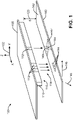
- a scanner 100 has a scan bar 110.
- the scan bar 110 is attached to a portion 105 of the scanner 100 in a fixed position, and the scan bar 110 does not move during a scan or imaging operation.
- the scan bar 110 has a substantially linear array of imaging elements 112 (several of which are illustrated).
- the imaging elements 112 each has a field of view, and are aimed in an imaging direction 114 orthogonal to the linear array.
- the scan bar 110 may include a lens array (not shown) that causes the field of view to have a predefined depth of field.
- the lens array is a rod lens array.
- the scanner 100 also has a built-in, translatable calibration target 140.
- the target 140 is spaced apart from, and parallel to, the scan bar 110. More particularly, the target 140 has a planar, flat surface 142 which is orthogonal to the imaging direction 114. The planar surface 142 defines an X-Y plane of a coordinate system 102.
- the target 140 has a size in the X direction that spans at least the distance in the X direction viewed by the scan bar 110, and a size in the Y direction that spans at least the distance in the Y direction viewed by the scan bar 110 throughout the translation of the target 140.
- the planar surface 142 is spaced apart from a planar surface 116 of the scan bar 110 by a distance S 120 in the Z direction of the coordinate system 102.
- the spacing S 120 may be less than a predefined distance.
- the imaging elements 112 may be CIS elements, and the spacing S 120 may be 0.2 millimeters or less. Each imaging element 112 may view a corresponding imaged region 144 of the planar surface 142 for a given position of the target 140.
- the target 140 is translatable within the scanner 100, and thus translatable with respect to the fixed-position scan bar 110.
- the target 140 translates in a given direction in the X-Y plane so as to maintain the spacing S 120 during translation.
- the target 140 is wider in the Y direction than the size of an imaged region 144.
- the target 140 may translate by a distance of at least 0.20 millimeters.
- the target 140 may translate by a distance proportional to the size of the defect and the size of the imaged region 144, such that scan output corresponding to the defect can be excluded.
- the target 140 translates during a calibration operation, and is maintained in a fixed position during a document scanning operation. The fixed position used during document scanning may be predefined.
- the direction of translation of the target 140 in the X-Y plane may be in a direction 146 that is orthogonal to the linear array of imaging elements 112. In this case, the imaged region 144 moves along a linear zone 147 of the planar surface 142.
- the direction of translation of the target 140 in the X-Y plane is in a direction 148 that is non-orthogonal to the linear array of imaging elements 112. In that case, the imaged region 144 falls along a linear zone 149 of the planar surface 142.
- the non-orthogonal direction 148 may provide increased calibration robustness in case of a blemished or damaged target surface 142.
- the target 140 has a sufficient width in the Y direction to ensure that all of zones 147, 149 fall onto the target 140.
- planar surface 142 of a target 140 (which is not damaged or blemished) is substantially uniform in color. In some examples, this planar surface 142 is substantially white in color.
- a document scanner 200 includes the scan bar 110 and the target 140.
- a document 220 is fed through the scanner 200 between the scan bar 110 and the target 140 in a predetermined direction 205.
- the target 140 is attached to, or in some cases integral to, a bias plate assembly 250.
- the bias plate assembly 250 maintains the surface 222 of the document 220 at a spacing from the surface 116 of the scan bar 110 which allow high quality imaging. In some examples, the bias plate assembly 250 does this by contacting the document 220 and urging the opposite surface 222 of the document 220 against the surface 116 of the scan bar 110.
- At least an upper portion of the bias plate assembly 250 which may include the target 140, is movable in the Z direction of the coordinate system 102 so as to allow the surface 222 of various documents to be properly spaced apart from the surface 116.
- the upper portion of the bias plate assembly 250, including the target 140, may also be compliant so as to conform to irregularities in the surface 116 of the scan bar 110 and/or the document 220, particularly in situations where the bias plate assembly 250 contacts the surface 116 directly, or indirectly via the document 220.
- the direction of translation in the X-Y plane of the target 140 is the same as the document feed direction 205. In other examples, the direction of translation of the target 140 is a different direction in the X-Y plane from the document feed direction 205.
- the calibration target 140 also provides a background for a transparent or translucent document 220 during scanning.
- scan defects including shadows can result if the scanner 100, 200 does not provide a background of a uniform color (in some examples, white) for the portion of the document being scanned.
- the uniform color of the target 140 minimizes or prevents such scan defects when scanning generally transparent or translucent documents 220.
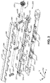
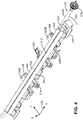
- a bias plate assembly 300 includes a base 310, a carrier 320, at least one resilient member (which can take many forms as described below), and a bias plate 340 having a calibration target 350.
- the bias plate assembly 300 is coupled to a drive system 370 that is coupled to the carrier 320 to controllably slide the carrier 320 relative to the base 310.
- the drive system includes a drive 375, a cam shaft 380, at least one cam 385, and a bearing 390.
- FIG. 3 depicts an exploded view of the bias plate assembly.
- FIG. 4 depicts an assembled view of the bias plate assembly.
- the bias plate assembly 300 is constructed mostly of low-cost molded plastic parts.
- the bias plate 340 has the calibration target 350 attached to it, or integrally formed in or on it.
- the calibration target 350 is flat and uniform in color, and may be the calibration target 140 ( FIGS. 1-2 ).
- a low rib 342 extends above the target 350 in the Z direction of the coordinate system 302. When the bias plate 340 is in contact with a document 220 ( FIG. 2 ) being scanned, or with the surface 116 of the scan bar 110 ( FIGS. 1-2 ), the rib 342 creates a small gap between the surface 116 and the target 350. This gap maintains a predefined spacing between the surface 116 and the target 350, and also protects the target 350 from wear due to contact with the document 220 or with the surface 116 of the scan bar 110.
- the bias plate 340 is flexible and compliant so as to conform to the surface 116.
- the bias plate 340 is molded of a low-cost uniform white ABS (acrylonitrile butadiene styrene) plastic material.
- the bias plate 340 may be metal or another substance.
- the bias plate 340 also has a ramped lead-in surface 344 to assist with smoothly feeding the document 220 between the scan bar 110 and bias plate 340 and preventing jamming.
- At least one snap 346 of the bias plate 340 fixedly attach the bias plate 340 to the carrier 320. The snaps 346 allow the bias plate 340, including the target 350, to be snapped off the carrier 320 to allow convenient replacement by a user instead of specially trained service personnel.
- each resilient member is a coil spring 330.
- the resilient member is a leaf spring, a compressible material, or another suitable component. If no document is inserted for scanning, the coil springs 330 urge the bias plate 340 against the surface 116 of the scan bar 110. If a document is inserted for scanning, the coil springs 330 urge the bias plate 340 against the document 220 whose surface 222 is in turn urged against the surface116 of the scan bar 110.
- the coil springs 330 are tuned with regard to the force they apply in order to minimize or eliminate document jamming.
- the carrier 320 retains the bias plate 340 and houses the coil springs 330.
- Each end of a coil spring 330 may be engaged by a post 322 on the carrier, and a corresponding post (not shown) on the bias plate 340.
- Each snap 346 connects to a corresponding receptacle 324.
- Force applied by the coil springs 330 to the bias plate 340 and carrier 320 assist in maintaining the connection between the bias plate 340 and the carrier 320.
- Disposing coil springs 330 at various intervals along the length of the carrier 320 allows each to be compressed a different amount, which assists the bias plate 340 to conform to irregularities in the surface 116 of the scan bar 110 and/or the document 220 to maintain the proper spacing to the scan bar 110.
- the carrier 320 includes at least one pair of cam engagement pockets 326A, 326B (collectively 326).
- the pockets 326 may have an upside-down U shape sized to engage cams of the drive system 370, as discussed in more detail subsequently with reference to FIGS. 6A-6B , in order to translate the bias plate 340.
- Pockets 326A extend along the Y axis from a front side of the carrier 320, while pockets 326B extend along the Y axis from the opposite rear side of the carrier 320.
- Pockets 326A, 326B facilitate the use of multiple bias plate assemblies with a single drive system, as discussed subsequently with reference to FIG. 7 .
- the carrier 320 also includes at least one base engagement feature on the underside of the carrier 320.
- the base engagement feature may be, in one example, a rib 328 which slideably engages a guide feature on the base 310 to facilitate translation of the bias plate 340.
- the base engagement feature is a pin, a slot, or another suitable feature.
- the base 310 retains the carrier 320. In one example, at least one hook 312 on the base 310 each engage a corresponding slot 329 on the carrier 320.
- the base 310 also attaches the carrier 320 to the chassis (not shown) of the scanner.
- the base 310 is attached to the chassis in a fixed position.
- the base 310 also translatably engages the carrier 320.
- the base 310 and carrier 320 are slidably engaged. This engagement is via at least one guide feature on the base 310.
- the guide feature is a guide slot 314 which engages a mating rib 328 of the carrier 320.
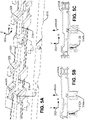
- the guide slot 314 controls the direction of translation of the bias plate 340, as discussed subsequently with reference to FIGS. 5A-5C .
- the drive 375 controllably rotates the cam shaft 380 to which it is coupled by a desired amount.
- the drive 375 is depicted as a single gear fixed to the cam shaft 380, and other portions of the drive 375 are not shown.
- the cam shaft 380 rotates under control of the drive 375. At least one cam 385 is disposed at an angular position on the cam shaft 380. The shape and position of the cams 385 control the speed and distance of the bias plate translation as the cam shaft 380 is rotated. The cams 385 that engage an individual bias plate assembly are usually disposed at the same angular position on the cam shaft 380.
- Each bearing 390 supports and locates the cam shaft 380.
- Each bearing 390 is affixed to the chassis of the scanner.
- the bearing is formed of a lubricious material with a favorable tribology such that the cam shaft 380 can rotate without excessive drag over the lifetime of the scanner.
- a rack-and-pinion system could dispose a small gear mesh on the bottom of the carrier 320 to engage with a corresponding gear on the cam shaft 380.
- the direction of translation of the bias plate 340 is governed by the direction of the rib 328 and the guide slot 314.
- the base 310A of FIG. 5B provides for translating the bias plate 340 (and the calibration target 350) in a direction 502A that is orthogonal to the linear array of imaging elements 112 of the scan bar 110 ( FIGS. 1-2 ).
- the guide slot 314A and the rib 328 extend in the orthogonal direction 502A.
- the base 310B of FIG. 5C provides for translating the bias plate 340 (and the calibration target 350) in a direction that is non-orthogonal to the linear array of imaging elements 112 of the scan bar 110.
- the guide slot 314B and the rib 328 extend in the non-orthogonal direction 502B.
- Such non-orthogonal translation may be advantageous in distinguishing a defective imaging element 112 from a scratch or blemish on the calibration target 350 that is oriented in the direction of translation and long enough to span the entire distance of translation.
- any scratch or blemish on the calibration target 350 will be captured by different imaging elements 112 as the target 350 is translated. This indicates that these various imaging elements 112 themselves are all functional, and that the calibration target 350 is scratched or blemished. As discussed subsequently with reference to FIG. 9 , a scratch or blemish can be compensated for when doing the calibration.
- each slot 329 on the carrier 320 is longer in the direction of translation of the bias plate 340 than the length of its corresponding hook 312 on the base 310. This allows the slot 329 to translate with respect to the hook 312 during translation of the bias plate 340.
- the hook 312, and its mating slot 329, are angled in the same direction 502A, 502B as the guide slot 314 and rib 328. Hooks 312A, 312B of FIGS. 5B-5C illustrate such angling for the orthogonal and non-orthogonal case respectively.
- the scanner is oriented such that the front is to the left and the rear to the right.
- the base 310 is fixed to the scanner chassis 630.
- the calibration target 350, and a portion of the bias plate 340, protrude above a document-receiving platen 620 through an aperture in the platen 620.
- the bias plate 340 and calibration target 350 are positioned at a rear-most document scanning position, and the coil springs 330 have urged the rib 342 of the bias plate into contact with the viewing surface 612 of a scan bar 610.
- the cam shaft 380 is rotated clockwise an amount such that the cam 385 contacts the external right side wall of the pocket 326B of the carrier 320, and continues to rotate to translate the carrier 320 and its attached bias plate 340 and calibration target 350 into the rear-most document scanning position, where it is maintained during scanning.
- a document is fed into the scanner in direction 604 above the platen 620, and the lead-in 344 of the bias plate 340 directs the document between the rib 342 and the viewing surface 612.
- the bias plate 340 is pressed down by the document to allow it to flow through the scanner, compressing the coil spring 330 a corresponding amount.
- the document is imaged by the scan bar 610 at the line-of-sight 614.
- the rib 342 serves as the wear point for contact with the document and creates a gap 616 between the calibration target 350 and the scan bar viewing surface 612, thus protecting the calibration target 350 from damage by the document.
- the bias plate 340 and calibration target 350 are illustrated positioned at a front-most position within the scanner, after being translated a distance in a direction having at least a component 618 in the -Y direction of the coordinate system 602 during a calibration process.
- the cam shaft 380 is rotated counter-clockwise an amount such that the cam 385 contacts the internal left side wall of the pocket 326B of the carrier 320, and continues to rotate to translate the carrier 320 and its attached bias plate 340 and calibration target 350 from the rear-most position into the front-most position.
- the imaging elements of the scan bar 610 each image a zone (e.g.
- the line-of-sight 614 views a different position of the calibration target 350 than the rear-most position of FIG. 6A .
- the calibration process is described subsequently in greater detail with reference to FIG. 9 .
- a multiple scan bar array may be used for scanning documents having widths greater than the span of a single scan bar.
- the scan bars may be offset from each other so as to provide an overlap area between every two scan bars where both scan bars can image the corresponding portion of the document.
- the images captured by each scan bar can be stitched together to form a composite image representing the entire document.
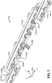
- An example array 700 includes three translatable bias plate assemblies 710A-710C (collectively 710).
- Each bias plate assembly 710 may be the bias plate assembly 300 ( FIG. 4 ), and each bias plate assembly 710 includes a calibration target.
- FIG. 7 a portion of each end bias plate assembly 710A, 710C is illustrated, while all of the middle bias plate assembly 710B is illustrated.
- Each bias plate assembly 710 includes a calibration target 350.
- the example array 700 has a single common drive system that translates all of the bias plate assemblies 710 and calibration targets.
- the cams 385 on the single cam shaft 380 may engage the front pockets 326A or the rear pockets 326B of an individual bias plate assembly 710.
- the cams 385 engage the rear-side pockets 326B of each end bias plate assembly 710A, 710C, while the cams 385 engage the front-side pockets 326A of the middle bias plate assembly 710A.
- the bias plate assemblies 710 may translate in the same direction.
- the cams 385 are fixed at the same angular position on the cam shaft 380 so as to translate all bias plate assemblies 710 synchronously or in unison.
- the cams 385 for each bias plate assembly 710 can be fixed at different angular positions on the cam shaft 380 so as to translate the various bias plate assemblies 710 sequentially. Sequential translation of bias plate assemblies may be useful in reducing bandwidth requirements for calibration processing, since the calibration of different scan bars can be performed at different times, rather than simultaneously.
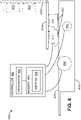
- a scanner 800 includes plural scan bars 810 in a staggered arrangement.
- a platen 820 is located on the surface of a housing 805, a portion of which is illustrated.
- the upper portion of bias plate assemblies 830 each having a calibration target protrudes from the housing 805 above the platen 820.
- Each bias plate assembly 830 may be the bias plate assembly 300 ( FIG. 4 ).
- the scanner 800 also includes a document transport mechanism 840, a drive system 850 for the bias plate assemblies 830, and a controller 860.
- the controller 860 is communicatively coupled to the document transport mechanism 840, the drive system 850, and the scan bars 810.
- the controller 860 includes a processor 862 coupled to a computer-readable medium such as a memory 864.
- the processor 862 executes instructions 866 stored in the memory 864 to control the document transport mechanism 840 to feed documents through the scanner 800, the scan bars 810 to image the documents and/or the calibration targets, and drive system 850 to translate the bias plates and calibration targets of the bias plate assemblies 830.
- the scan bars 810 may be attached to a structural member of the scanner 800.
- the structural member is attached to a movable cover of the scanner 800.
- the structural member is depicted in two different positions: an operating position 870 (solid line) and a service position 870' (dashed line).
- the structural member positions scan bars 810 in their normal operating position 870 adjacent bias plate assemblies 830.
- the scan bars 810 are moved out of their operational position when the structural member is moved to the service position 870'.
- the user of the scanner has access to the bias plate assemblies 830, and can easily clean, remove, and/or replace the bias plate (e.g. bias plate 340, FIGS. 3-4 ).
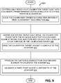
- a method 900 begins at 902 by controllably moving a planar, flat translatable calibration target built into the scanner a predetermined distance relative to a fixed-position scan bar of the scanner.
- the target may be moved from an initial position used during document scanning.
- the calibration target is translated within the plane of the surface of the calibration target.
- the calibration target is moved in a direction different from a document feed direction of the document through the scanner.
- the calibration target is repeatedly imaged with the scan bar during the moving such that each imaging element of the scan bar captures image signals for a zone (e.g. zone 147 and/or 149) of a flat surface of the calibration target.
- the calibration target is urged against an imaging surface of the scan bar during the moving.
- the captured image signals from each imaging element are processed to calibrate the scanner.
- the processing includes calibrating the scan bar for white point and uniformity.
- Each imaging element of a scan bar may have a different response characteristic (photo response non-uniformity, or PRNU) from other imaging elements.
- Calibrating for white point involves generating a white point calibration constant per color for an imaging element based on the output of that imaging element resulting from scanning the white calibration target.
- Calibrating for uniformity involves generating these calibration constants for all imaging elements of the scan bar in order to make the response from all imaging elements uniform across the scan bar.
- the processing 912 reduces or eliminates the effect on the white point and uniformity of blemishes, scratches, or other damage to the calibration target. For example, the processing may average the series of images, or may discard or give less weight to outliers in the series of images which may correspond to the damage. As a result, the processing 912 generates a more accurate calibration than a calibration which is based on measurements made with a static calibration target.
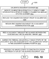
- a method 1000 begins at 900 by calibrating a document scanner without use of a calibration document being fed through the scanner.
- the calibration 900 is automatically initiated by the scanner without user intervention and without feeding a calibration medium into the scanner.
- a user replaces the calibration target prior to the calibration 900.
- the calibration target is returned to an initial position after the calibration 900.
- the initial position may be a document scanning position of the target.
- a document is fed through the scanner between the scan bar and the calibration target.
- strips of the document are sequentially imaged with the scan bar as the document is being fed through the scanner.
- the calibration target is maintained in the initial (scanning) position.
- the imaged strips are processed to construct a digital representation of the scanned document.
- At least one block or step discussed herein is automated.
- apparatus, systems, and methods occur automatically.
- automated or “automatically” (and like variations thereof) shall be broadly understood to mean controlled operation of an apparatus, system, and/or process using computers and/or mechanical/electrical devices without the necessity of human intervention, observation, effort and/or decision.
- a large planar calibration target parallel to the scan bar minimizes sensitivity to part and assembly tolerances, and minimized luminance variation during calibration and scanning.
- a relatively long distance of translation of the calibration target during a calibration process maximizes the ability to compensate for damage to, or blemishes on, the calibration targets.
- damage or blemishes on the target can be distinguished from defective imaging elements and can be factored out of the calibration.
- the calibration target provides a shadow-eliminating background during scanning.
- a leading rib protects the calibration target from damage during document scanning, and the calibration target can be easily cleaned or replaced by the user of the scanner.
Landscapes
- Engineering & Computer Science (AREA)
- Multimedia (AREA)
- Signal Processing (AREA)
- Health & Medical Sciences (AREA)
- Biomedical Technology (AREA)
- General Health & Medical Sciences (AREA)
- Facsimile Scanning Arrangements (AREA)
- Image Input (AREA)
Claims (11)
- Scanner de documents (100, 200, 800), comprenant :un réseau de barres de balayage comprenant une barre de balayage à position fixe ou plusieurs barres de balayage à position fixe décalées se chevauchant, chaque barre de balayage ayant un réseau linéaire (110) d'éléments d'imagerie (112) orientés dans une direction d'imagerie ;une cible d'étalonnage translatable intégrée (140, 350) espacée du réseau linéaire (110) de la barre de balayage à position fixe et parallèle à celui-ci, ou un réseau de cibles d'étalonnage translatables intégrées en quinconce se chevauchant (350) espacées des réseaux linéaires (110) de barres correspondantes des multiples barres de balayage à position fixe et parallèles à ceux-ci, la ou chaque cible d'étalonnage ayant une surface planaire (142) orthogonale à la direction d'imagerie et couvrant la longueur du réseau linéaire ; etun système d'entraînement (370, 850) pour translater la ou chaque cible d'étalonnage (140, 350) pendant un étalonnage dans une direction dans un plan de la surface planaire qui n'est pas orthogonale à la longueur du réseau linéaire (110) d'éléments d'imagerie (112) ;dans lequel chaque cible d'étalonnage (350) est supportée par un ensemble, le ou chaque ensemble comprenant une plaque de polarisation souple (340) ayant la cible d'étalonnage (350) et un élément élastique (330) pour pousser la plaque de polarisation souple (340) vers le réseau linéaire (110).
- Scanner (100, 200, 800) selon la revendication 1, dans lequel le ou chaque ensemble comprend en outre :un support (320) fixé de manière amovible à la plaque de polarisation souple (340) ;une base (310) fixée de manière translatable au support (320) et fixée de manière fixe à un châssis (630) du scanner (100) ;l'élément élastique (330) étant retenu entre la plaque de polarisation (340) et le support (320), la plaque de polarisation pouvant se déplacer vers le support dans la direction d'imagerie pour comprimer l'élément élastique.
- Scanner (100, 200, 800) selon la revendication 2, dans lequel le système d'entraînement (370) est accouplé au support (320) pour translater de manière commandable le support par rapport à la base (310).
- Scanner (100, 200, 800) selon la revendication 2 ou 3, dans lequel l'élément élastique (330) doit pousser la plaque de polarisation (340) contre un boîtier du réseau linéaire (110), et dans lequel la plaque de polarisation, en étant souple, se conforme à une surface de contact (116) du boîtier.
- Scanner (100, 200, 800) selon la revendication 4, dans lequel une nervure (342) de la plaque de polarisation souple (340) est poussée contre le boîtier, la nervure (342) maintenant un espacement prédéfini entre la cible d'étalonnage (350) et le boîtier.
- Scanner (100, 200, 800) selon l'une quelconque des revendications précédentes, dans lequel la surface planaire de la ou de chaque cible d'étalonnage (140, 350) a une couleur uniforme et est un arrière-plan pour numériser des documents transparents et translucides (220).
- Scanner (800) selon l'une quelconque des revendications précédentes, dans lequel, dans le cas où il y a un réseau de cibles d'étalonnage, le système d'entraînement (850) comprend :un arbre à cames rotatif (380) ;une pluralité de cames (385) fixées chacune à l'arbre à cames (380) à une position angulaire ; etune pluralité d'éléments de mise en prise de came, chacun accouplé à l'une des cibles d'étalonnage (350) correspondante et mis en prise avec une des cames (385) correspondante.
- Procédé (900) d'étalonnage, sans document d'étalonnage, d'un scanner de documents selon l'une quelconque des revendications précédentes, le procédé comprenant :le déplacement (902) de manière commandable de la ou de chaque cible d'étalonnage dans une direction dans un plan de la surface planaire de la cible d'étalonnage qui n'est pas orthogonale à la longueur du réseau linéaire d'éléments d'imagerie ;pendant le déplacement (902), la réalisation d'imagerie de manière répétée (906) de la ou de chaque cible d'étalonnage avec la barre de balayage à position fixe correspondante de telle sorte que chaque élément d'imagerie de la barre de balayage à position fixe capture des signaux pour une zone d'une surface de couleur uniforme et plate du cible d'étalonnage ; etle traitement (912) des signaux capturés à partir de chaque élément d'imagerie pour étalonner le scanner.
- Procédé (900) selon la revendication 8, dans lequel le traitement (912) comporte l'étalonnage (914) du point blanc et/ou de l'uniformité de la ou de chaque barre de balayage à position fixe.
- Procédé (900) selon la revendication 8, comprenant en outre, après le traitement (912) :le retour de la ou de chaque cible d'étalonnage à une position initiale ;l'alimentation d'un document à travers le scanner entre la ou chaque barre de balayage à position fixe et la cible d'étalonnage correspondante ;pendant l'alimentation, la réalisation séquentielle d'imagerie des bandes du document avec la ou chaque barre de balayage à position fixe avec la ou chaque cible d'étalonnage dans la position initiale ; etle traitement des bandes imagées pour construire une représentation numérique du document.
- Procédé (900) selon la revendication 8, comprenant en outre :
pendant le déplacement (902), la poussée de la ou de chaque cible d'étalonnage contre une surface de la barre de balayage à position fixe correspondante.
Applications Claiming Priority (1)
| Application Number | Priority Date | Filing Date | Title |
|---|---|---|---|
| PCT/US2014/063322 WO2016068977A1 (fr) | 2014-10-31 | 2014-10-31 | Cible translatable d'étalonnage de scanner |
Publications (3)
| Publication Number | Publication Date |
|---|---|
| EP3213496A1 EP3213496A1 (fr) | 2017-09-06 |
| EP3213496A4 EP3213496A4 (fr) | 2018-06-20 |
| EP3213496B1 true EP3213496B1 (fr) | 2022-11-30 |
Family
ID=55858078
Family Applications (1)
| Application Number | Title | Priority Date | Filing Date |
|---|---|---|---|
| EP14904652.6A Active EP3213496B1 (fr) | 2014-10-31 | 2014-10-31 | Cible translatable d'étalonnage de scanner |
Country Status (4)
| Country | Link |
|---|---|
| US (2) | US10097714B2 (fr) |
| EP (1) | EP3213496B1 (fr) |
| CN (1) | CN107079073B (fr) |
| WO (1) | WO2016068977A1 (fr) |
Citations (3)
| Publication number | Priority date | Publication date | Assignee | Title |
|---|---|---|---|---|
| JP2003219124A (ja) * | 2002-01-21 | 2003-07-31 | Sharp Corp | 画像読取り装置 |
| US20050133742A1 (en) * | 2003-12-22 | 2005-06-23 | Daniel Stuart W. | Method for shading an optical sensing element such as in a scanner |
| US7224484B1 (en) * | 2000-10-04 | 2007-05-29 | Reeves Gerald J | Scanner calibration with dead pixel compensation |
Family Cites Families (20)
| Publication number | Priority date | Publication date | Assignee | Title |
|---|---|---|---|---|
| US4433298A (en) * | 1981-11-12 | 1984-02-21 | Datapoint Corporation | Calibrated apparent surface voltage measurement apparatus and method |
| US5280368A (en) * | 1992-11-02 | 1994-01-18 | Xerox Corporation | Fixed full width array scan head calibration apparatus |
| GB2312304B (en) | 1996-04-18 | 1999-12-29 | Ibm | Improvements in printing |
| US6400468B1 (en) * | 1998-03-31 | 2002-06-04 | International Business Machines Corporation | Smoothing calibration files to improve reproduction of digitized images |
| JP4485618B2 (ja) | 1999-06-18 | 2010-06-23 | 東芝テック株式会社 | 画像読取装置 |
| US6470099B1 (en) | 1999-06-30 | 2002-10-22 | Hewlett-Packard Company | Scanner with multiple reference marks |
| US6900448B1 (en) * | 2000-07-31 | 2005-05-31 | Hewlett-Packard Development Company L.P. | Method and system for dynamic scanner calibration |
| JP2004140474A (ja) | 2002-10-15 | 2004-05-13 | Canon Inc | 画像読取装置 |
| CN100490490C (zh) * | 2006-01-20 | 2009-05-20 | 虹光精密工业(苏州)有限公司 | 扫描仪的校正机构 |
| AU2007203556B2 (en) | 2007-07-31 | 2011-03-10 | Canon Kabushiki Kaisha | Calibration chart configuration system |
| US7973935B2 (en) * | 2007-11-06 | 2011-07-05 | Konica Minolta Sensing, Inc. | Reflection characteristic measuring apparatus for sheet specimen and method of calibrating reflection characteristic measuring apparatus for sheet specimen |
| US20090168116A1 (en) * | 2007-12-26 | 2009-07-02 | Chengwu Cui | Method and System For Calibrating A Scanner Having A Scan Bar Including Sensor Elements |
| CN102203680A (zh) * | 2008-10-30 | 2011-09-28 | 惠普开发有限公司 | 成像装置校准系统和方法 |
| US8310735B2 (en) * | 2010-01-27 | 2012-11-13 | Hewlett-Packard Development Company, L.P. | Image capture module support |
| US8767056B2 (en) | 2010-03-05 | 2014-07-01 | Siemens Industry, Inc. | Flat-folding document imaging apparatus |
| KR101768536B1 (ko) | 2010-11-29 | 2017-08-18 | 에스프린팅솔루션 주식회사 | 원고 스캐닝 장치 및 이를 구비하는 화상 형성 장치 |
| JP5812636B2 (ja) | 2011-03-18 | 2015-11-17 | キヤノン株式会社 | スキャナ装置 |
| DE102011018381B4 (de) | 2011-04-21 | 2014-09-11 | Roth + Weber Gmbh | Großformatiges Scanner-System |
| JP2014060492A (ja) | 2012-09-14 | 2014-04-03 | Ricoh Co Ltd | 傾き調整機構、撮像ユニット装置、画像走査装置、画像読取装置、及び複写機 |
| US8786914B1 (en) * | 2013-02-26 | 2014-07-22 | Hewlett-Packard Development Company, L.P. | Scanner |
-
2014
- 2014-10-31 EP EP14904652.6A patent/EP3213496B1/fr active Active
- 2014-10-31 CN CN201480083162.4A patent/CN107079073B/zh active Active
- 2014-10-31 WO PCT/US2014/063322 patent/WO2016068977A1/fr not_active Ceased
- 2014-10-31 US US15/519,860 patent/US10097714B2/en active Active
-
2018
- 2018-08-24 US US16/112,140 patent/US10477054B2/en active Active
Patent Citations (3)
| Publication number | Priority date | Publication date | Assignee | Title |
|---|---|---|---|---|
| US7224484B1 (en) * | 2000-10-04 | 2007-05-29 | Reeves Gerald J | Scanner calibration with dead pixel compensation |
| JP2003219124A (ja) * | 2002-01-21 | 2003-07-31 | Sharp Corp | 画像読取り装置 |
| US20050133742A1 (en) * | 2003-12-22 | 2005-06-23 | Daniel Stuart W. | Method for shading an optical sensing element such as in a scanner |
Also Published As
| Publication number | Publication date |
|---|---|
| US10477054B2 (en) | 2019-11-12 |
| WO2016068977A1 (fr) | 2016-05-06 |
| EP3213496A4 (fr) | 2018-06-20 |
| US20180367691A1 (en) | 2018-12-20 |
| US10097714B2 (en) | 2018-10-09 |
| CN107079073B (zh) | 2019-11-12 |
| US20170318173A1 (en) | 2017-11-02 |
| CN107079073A (zh) | 2017-08-18 |
| EP3213496A1 (fr) | 2017-09-06 |
Similar Documents
| Publication | Publication Date | Title |
|---|---|---|
| EP1463298A1 (fr) | Appareil et procédé de lecture d'images capable d'obtenir des données de référence de blanc pour la correction de l'effet d'ombre | |
| EP2541888B1 (fr) | Dispositif de lecture d'images | |
| US20110211223A1 (en) | Image forming apparatus | |
| US8817344B2 (en) | Scanner apparatus | |
| US8786914B1 (en) | Scanner | |
| JP6800690B2 (ja) | 画像読取装置及び白基準シート部材 | |
| JP2006041708A (ja) | 画像読み取り装置 | |
| JP2008187531A (ja) | 画像読取装置及び画像形成装置 | |
| JP2002290685A (ja) | 画像読み取り装置及び入力素子の補正方法 | |
| EP3213496B1 (fr) | Cible translatable d'étalonnage de scanner | |
| US9769348B2 (en) | Apparatus and method for optimizing the calibration position for document scanner calibration using a calibration strip | |
| US20060279803A1 (en) | Calibration system for a scanner for recording images from sheets | |
| JP6891463B2 (ja) | 画像形成装置、およびプログラム | |
| JP2003140275A (ja) | 画像読取装置 | |
| US6667817B1 (en) | Multiple resolution scanner with improved lamp intensity monitoring capabilities | |
| JP5746844B2 (ja) | 画像読取装置及び画像形成装置 | |
| US8976427B2 (en) | Image forming apparatus and method of controlling the same | |
| JP4706658B2 (ja) | 画像読取装置調整方法、画像読取装置、画像読取装置調整用治具 | |
| US10827094B2 (en) | Reading apparatus | |
| US9871931B1 (en) | Scanner capable of executing static calibration and compensation value adjustment method therefor | |
| JP2008028699A (ja) | 画像読取装置及び該方法 | |
| US20170019555A1 (en) | Image reading apparatus | |
| JP6045538B2 (ja) | 画像読取装置および調整方法 | |
| JP7556256B2 (ja) | 読取装置、画像形成装置および方法 | |
| US10764460B2 (en) | Image sensor unit, image reading device, and image forming device having rod-shaped light guide |
Legal Events
| Date | Code | Title | Description |
|---|---|---|---|
| STAA | Information on the status of an ep patent application or granted ep patent |
Free format text: STATUS: THE INTERNATIONAL PUBLICATION HAS BEEN MADE |
|
| PUAI | Public reference made under article 153(3) epc to a published international application that has entered the european phase |
Free format text: ORIGINAL CODE: 0009012 |
|
| STAA | Information on the status of an ep patent application or granted ep patent |
Free format text: STATUS: REQUEST FOR EXAMINATION WAS MADE |
|
| 17P | Request for examination filed |
Effective date: 20170407 |
|
| AK | Designated contracting states |
Kind code of ref document: A1 Designated state(s): AL AT BE BG CH CY CZ DE DK EE ES FI FR GB GR HR HU IE IS IT LI LT LU LV MC MK MT NL NO PL PT RO RS SE SI SK SM TR |
|
| AX | Request for extension of the european patent |
Extension state: BA ME |
|
| DAX | Request for extension of the european patent (deleted) | ||
| A4 | Supplementary search report drawn up and despatched |
Effective date: 20180524 |
|
| RIC1 | Information provided on ipc code assigned before grant |
Ipc: H04N 1/03 20060101ALN20180517BHEP Ipc: H04N 1/028 20060101ALI20180517BHEP Ipc: H04N 1/10 20060101ALI20180517BHEP Ipc: H04N 1/12 20060101ALN20180517BHEP Ipc: H04N 1/00 20060101ALN20180517BHEP Ipc: H04N 5/367 20110101ALN20180517BHEP Ipc: H04N 1/04 20060101AFI20180517BHEP |
|
| RAP1 | Party data changed (applicant data changed or rights of an application transferred) |
Owner name: HEWLETT-PACKARD DEVELOPMENT COMPANY, L.P. |
|
| STAA | Information on the status of an ep patent application or granted ep patent |
Free format text: STATUS: EXAMINATION IS IN PROGRESS |
|
| 17Q | First examination report despatched |
Effective date: 20210208 |
|
| RIC1 | Information provided on ipc code assigned before grant |
Ipc: H04N 5/367 20110101ALN20220616BHEP Ipc: H04N 1/12 20060101ALN20220616BHEP Ipc: H04N 1/00 20060101ALN20220616BHEP Ipc: H04N 1/03 20060101ALN20220616BHEP Ipc: H04N 1/409 20060101ALI20220616BHEP Ipc: H04N 1/028 20060101ALI20220616BHEP Ipc: H04N 1/10 20060101ALI20220616BHEP Ipc: H04N 1/04 20060101AFI20220616BHEP |
|
| GRAP | Despatch of communication of intention to grant a patent |
Free format text: ORIGINAL CODE: EPIDOSNIGR1 |
|
| STAA | Information on the status of an ep patent application or granted ep patent |
Free format text: STATUS: GRANT OF PATENT IS INTENDED |
|
| INTG | Intention to grant announced |
Effective date: 20220727 |
|
| RIC1 | Information provided on ipc code assigned before grant |
Ipc: H04N 5/367 20110101ALN20220715BHEP Ipc: H04N 1/12 20060101ALN20220715BHEP Ipc: H04N 1/00 20060101ALN20220715BHEP Ipc: H04N 1/03 20060101ALN20220715BHEP Ipc: H04N 1/409 20060101ALI20220715BHEP Ipc: H04N 1/028 20060101ALI20220715BHEP Ipc: H04N 1/10 20060101ALI20220715BHEP Ipc: H04N 1/04 20060101AFI20220715BHEP |
|
| GRAS | Grant fee paid |
Free format text: ORIGINAL CODE: EPIDOSNIGR3 |
|
| GRAA | (expected) grant |
Free format text: ORIGINAL CODE: 0009210 |
|
| STAA | Information on the status of an ep patent application or granted ep patent |
Free format text: STATUS: THE PATENT HAS BEEN GRANTED |
|
| AK | Designated contracting states |
Kind code of ref document: B1 Designated state(s): AL AT BE BG CH CY CZ DE DK EE ES FI FR GB GR HR HU IE IS IT LI LT LU LV MC MK MT NL NO PL PT RO RS SE SI SK SM TR |
|
| REG | Reference to a national code |
Ref country code: CH Ref legal event code: EP Ref country code: GB Ref legal event code: FG4D |
|
| REG | Reference to a national code |
Ref country code: AT Ref legal event code: REF Ref document number: 1535596 Country of ref document: AT Kind code of ref document: T Effective date: 20221215 Ref country code: DE Ref legal event code: R096 Ref document number: 602014085702 Country of ref document: DE |
|
| REG | Reference to a national code |
Ref country code: IE Ref legal event code: FG4D |
|
| REG | Reference to a national code |
Ref country code: LT Ref legal event code: MG9D |
|
| REG | Reference to a national code |
Ref country code: NL Ref legal event code: MP Effective date: 20221130 |
|
| PG25 | Lapsed in a contracting state [announced via postgrant information from national office to epo] |
Ref country code: SE Free format text: LAPSE BECAUSE OF FAILURE TO SUBMIT A TRANSLATION OF THE DESCRIPTION OR TO PAY THE FEE WITHIN THE PRESCRIBED TIME-LIMIT Effective date: 20221130 Ref country code: PT Free format text: LAPSE BECAUSE OF FAILURE TO SUBMIT A TRANSLATION OF THE DESCRIPTION OR TO PAY THE FEE WITHIN THE PRESCRIBED TIME-LIMIT Effective date: 20230331 Ref country code: NO Free format text: LAPSE BECAUSE OF FAILURE TO SUBMIT A TRANSLATION OF THE DESCRIPTION OR TO PAY THE FEE WITHIN THE PRESCRIBED TIME-LIMIT Effective date: 20230228 Ref country code: LT Free format text: LAPSE BECAUSE OF FAILURE TO SUBMIT A TRANSLATION OF THE DESCRIPTION OR TO PAY THE FEE WITHIN THE PRESCRIBED TIME-LIMIT Effective date: 20221130 Ref country code: FI Free format text: LAPSE BECAUSE OF FAILURE TO SUBMIT A TRANSLATION OF THE DESCRIPTION OR TO PAY THE FEE WITHIN THE PRESCRIBED TIME-LIMIT Effective date: 20221130 Ref country code: ES Free format text: LAPSE BECAUSE OF FAILURE TO SUBMIT A TRANSLATION OF THE DESCRIPTION OR TO PAY THE FEE WITHIN THE PRESCRIBED TIME-LIMIT Effective date: 20221130 |
|
| REG | Reference to a national code |
Ref country code: AT Ref legal event code: MK05 Ref document number: 1535596 Country of ref document: AT Kind code of ref document: T Effective date: 20221130 |
|
| PG25 | Lapsed in a contracting state [announced via postgrant information from national office to epo] |
Ref country code: RS Free format text: LAPSE BECAUSE OF FAILURE TO SUBMIT A TRANSLATION OF THE DESCRIPTION OR TO PAY THE FEE WITHIN THE PRESCRIBED TIME-LIMIT Effective date: 20221130 Ref country code: PL Free format text: LAPSE BECAUSE OF FAILURE TO SUBMIT A TRANSLATION OF THE DESCRIPTION OR TO PAY THE FEE WITHIN THE PRESCRIBED TIME-LIMIT Effective date: 20221130 Ref country code: LV Free format text: LAPSE BECAUSE OF FAILURE TO SUBMIT A TRANSLATION OF THE DESCRIPTION OR TO PAY THE FEE WITHIN THE PRESCRIBED TIME-LIMIT Effective date: 20221130 Ref country code: IS Free format text: LAPSE BECAUSE OF FAILURE TO SUBMIT A TRANSLATION OF THE DESCRIPTION OR TO PAY THE FEE WITHIN THE PRESCRIBED TIME-LIMIT Effective date: 20230330 Ref country code: HR Free format text: LAPSE BECAUSE OF FAILURE TO SUBMIT A TRANSLATION OF THE DESCRIPTION OR TO PAY THE FEE WITHIN THE PRESCRIBED TIME-LIMIT Effective date: 20221130 Ref country code: GR Free format text: LAPSE BECAUSE OF FAILURE TO SUBMIT A TRANSLATION OF THE DESCRIPTION OR TO PAY THE FEE WITHIN THE PRESCRIBED TIME-LIMIT Effective date: 20230301 |
|
| PG25 | Lapsed in a contracting state [announced via postgrant information from national office to epo] |
Ref country code: NL Free format text: LAPSE BECAUSE OF FAILURE TO SUBMIT A TRANSLATION OF THE DESCRIPTION OR TO PAY THE FEE WITHIN THE PRESCRIBED TIME-LIMIT Effective date: 20221130 |
|
| PG25 | Lapsed in a contracting state [announced via postgrant information from national office to epo] |
Ref country code: SM Free format text: LAPSE BECAUSE OF FAILURE TO SUBMIT A TRANSLATION OF THE DESCRIPTION OR TO PAY THE FEE WITHIN THE PRESCRIBED TIME-LIMIT Effective date: 20221130 Ref country code: RO Free format text: LAPSE BECAUSE OF FAILURE TO SUBMIT A TRANSLATION OF THE DESCRIPTION OR TO PAY THE FEE WITHIN THE PRESCRIBED TIME-LIMIT Effective date: 20221130 Ref country code: EE Free format text: LAPSE BECAUSE OF FAILURE TO SUBMIT A TRANSLATION OF THE DESCRIPTION OR TO PAY THE FEE WITHIN THE PRESCRIBED TIME-LIMIT Effective date: 20221130 Ref country code: DK Free format text: LAPSE BECAUSE OF FAILURE TO SUBMIT A TRANSLATION OF THE DESCRIPTION OR TO PAY THE FEE WITHIN THE PRESCRIBED TIME-LIMIT Effective date: 20221130 Ref country code: CZ Free format text: LAPSE BECAUSE OF FAILURE TO SUBMIT A TRANSLATION OF THE DESCRIPTION OR TO PAY THE FEE WITHIN THE PRESCRIBED TIME-LIMIT Effective date: 20221130 Ref country code: AT Free format text: LAPSE BECAUSE OF FAILURE TO SUBMIT A TRANSLATION OF THE DESCRIPTION OR TO PAY THE FEE WITHIN THE PRESCRIBED TIME-LIMIT Effective date: 20221130 |
|
| PG25 | Lapsed in a contracting state [announced via postgrant information from national office to epo] |
Ref country code: SK Free format text: LAPSE BECAUSE OF FAILURE TO SUBMIT A TRANSLATION OF THE DESCRIPTION OR TO PAY THE FEE WITHIN THE PRESCRIBED TIME-LIMIT Effective date: 20221130 Ref country code: AL Free format text: LAPSE BECAUSE OF FAILURE TO SUBMIT A TRANSLATION OF THE DESCRIPTION OR TO PAY THE FEE WITHIN THE PRESCRIBED TIME-LIMIT Effective date: 20221130 |
|
| REG | Reference to a national code |
Ref country code: DE Ref legal event code: R097 Ref document number: 602014085702 Country of ref document: DE |
|
| PLBE | No opposition filed within time limit |
Free format text: ORIGINAL CODE: 0009261 |
|
| STAA | Information on the status of an ep patent application or granted ep patent |
Free format text: STATUS: NO OPPOSITION FILED WITHIN TIME LIMIT |
|
| 26N | No opposition filed |
Effective date: 20230831 |
|
| PG25 | Lapsed in a contracting state [announced via postgrant information from national office to epo] |
Ref country code: SI Free format text: LAPSE BECAUSE OF FAILURE TO SUBMIT A TRANSLATION OF THE DESCRIPTION OR TO PAY THE FEE WITHIN THE PRESCRIBED TIME-LIMIT Effective date: 20221130 |
|
| PG25 | Lapsed in a contracting state [announced via postgrant information from national office to epo] |
Ref country code: IT Free format text: LAPSE BECAUSE OF FAILURE TO SUBMIT A TRANSLATION OF THE DESCRIPTION OR TO PAY THE FEE WITHIN THE PRESCRIBED TIME-LIMIT Effective date: 20221130 Ref country code: MC Free format text: LAPSE BECAUSE OF FAILURE TO SUBMIT A TRANSLATION OF THE DESCRIPTION OR TO PAY THE FEE WITHIN THE PRESCRIBED TIME-LIMIT Effective date: 20221130 |
|
| REG | Reference to a national code |
Ref country code: CH Ref legal event code: PL |
|
| REG | Reference to a national code |
Ref country code: BE Ref legal event code: MM Effective date: 20231031 |
|
| PG25 | Lapsed in a contracting state [announced via postgrant information from national office to epo] |
Ref country code: LU Free format text: LAPSE BECAUSE OF NON-PAYMENT OF DUE FEES Effective date: 20231031 |
|
| GBPC | Gb: european patent ceased through non-payment of renewal fee |
Effective date: 20231031 |
|
| PG25 | Lapsed in a contracting state [announced via postgrant information from national office to epo] |
Ref country code: LU Free format text: LAPSE BECAUSE OF NON-PAYMENT OF DUE FEES Effective date: 20231031 |
|
| PG25 | Lapsed in a contracting state [announced via postgrant information from national office to epo] |
Ref country code: GB Free format text: LAPSE BECAUSE OF NON-PAYMENT OF DUE FEES Effective date: 20231031 |
|
| PG25 | Lapsed in a contracting state [announced via postgrant information from national office to epo] |
Ref country code: CH Free format text: LAPSE BECAUSE OF NON-PAYMENT OF DUE FEES Effective date: 20231031 |
|
| PG25 | Lapsed in a contracting state [announced via postgrant information from national office to epo] |
Ref country code: GB Free format text: LAPSE BECAUSE OF NON-PAYMENT OF DUE FEES Effective date: 20231031 Ref country code: FR Free format text: LAPSE BECAUSE OF NON-PAYMENT OF DUE FEES Effective date: 20231031 Ref country code: CH Free format text: LAPSE BECAUSE OF NON-PAYMENT OF DUE FEES Effective date: 20231031 |
|
| PG25 | Lapsed in a contracting state [announced via postgrant information from national office to epo] |
Ref country code: BE Free format text: LAPSE BECAUSE OF NON-PAYMENT OF DUE FEES Effective date: 20231031 |
|
| PG25 | Lapsed in a contracting state [announced via postgrant information from national office to epo] |
Ref country code: IE Free format text: LAPSE BECAUSE OF NON-PAYMENT OF DUE FEES Effective date: 20231031 |
|
| PG25 | Lapsed in a contracting state [announced via postgrant information from national office to epo] |
Ref country code: IE Free format text: LAPSE BECAUSE OF NON-PAYMENT OF DUE FEES Effective date: 20231031 |
|
| PG25 | Lapsed in a contracting state [announced via postgrant information from national office to epo] |
Ref country code: BG Free format text: LAPSE BECAUSE OF FAILURE TO SUBMIT A TRANSLATION OF THE DESCRIPTION OR TO PAY THE FEE WITHIN THE PRESCRIBED TIME-LIMIT Effective date: 20221130 |
|
| PG25 | Lapsed in a contracting state [announced via postgrant information from national office to epo] |
Ref country code: BG Free format text: LAPSE BECAUSE OF FAILURE TO SUBMIT A TRANSLATION OF THE DESCRIPTION OR TO PAY THE FEE WITHIN THE PRESCRIBED TIME-LIMIT Effective date: 20221130 |
|
| PG25 | Lapsed in a contracting state [announced via postgrant information from national office to epo] |
Ref country code: CY Free format text: LAPSE BECAUSE OF FAILURE TO SUBMIT A TRANSLATION OF THE DESCRIPTION OR TO PAY THE FEE WITHIN THE PRESCRIBED TIME-LIMIT; INVALID AB INITIO Effective date: 20141031 |
|
| PG25 | Lapsed in a contracting state [announced via postgrant information from national office to epo] |
Ref country code: HU Free format text: LAPSE BECAUSE OF FAILURE TO SUBMIT A TRANSLATION OF THE DESCRIPTION OR TO PAY THE FEE WITHIN THE PRESCRIBED TIME-LIMIT; INVALID AB INITIO Effective date: 20141031 |
|
| PG25 | Lapsed in a contracting state [announced via postgrant information from national office to epo] |
Ref country code: TR Free format text: LAPSE BECAUSE OF FAILURE TO SUBMIT A TRANSLATION OF THE DESCRIPTION OR TO PAY THE FEE WITHIN THE PRESCRIBED TIME-LIMIT Effective date: 20221130 |
|
| PGFP | Annual fee paid to national office [announced via postgrant information from national office to epo] |
Ref country code: DE Payment date: 20250923 Year of fee payment: 12 |