EP3213700B1 - Instrument médical - Google Patents
Instrument médical Download PDFInfo
- Publication number
- EP3213700B1 EP3213700B1 EP17155947.9A EP17155947A EP3213700B1 EP 3213700 B1 EP3213700 B1 EP 3213700B1 EP 17155947 A EP17155947 A EP 17155947A EP 3213700 B1 EP3213700 B1 EP 3213700B1
- Authority
- EP
- European Patent Office
- Prior art keywords
- distal end
- end portion
- shaft
- medical instrument
- transmission element
- Prior art date
- Legal status (The legal status is an assumption and is not a legal conclusion. Google has not performed a legal analysis and makes no representation as to the accuracy of the status listed.)
- Active
Links
Images


Classifications
-
- A—HUMAN NECESSITIES
- A61—MEDICAL OR VETERINARY SCIENCE; HYGIENE
- A61B—DIAGNOSIS; SURGERY; IDENTIFICATION
- A61B17/00—Surgical instruments, devices or methods
- A61B17/28—Surgical forceps
- A61B17/29—Forceps for use in minimally invasive surgery
-
- A—HUMAN NECESSITIES
- A61—MEDICAL OR VETERINARY SCIENCE; HYGIENE
- A61B—DIAGNOSIS; SURGERY; IDENTIFICATION
- A61B17/00—Surgical instruments, devices or methods
- A61B17/04—Surgical instruments, devices or methods for suturing wounds; Holders or packages for needles or suture materials
- A61B17/06—Needles ; Sutures; Needle-suture combinations; Holders or packages for needles or suture materials
- A61B17/062—Needle manipulators
-
- A—HUMAN NECESSITIES
- A61—MEDICAL OR VETERINARY SCIENCE; HYGIENE
- A61B—DIAGNOSIS; SURGERY; IDENTIFICATION
- A61B17/00—Surgical instruments, devices or methods
- A61B17/28—Surgical forceps
- A61B17/29—Forceps for use in minimally invasive surgery
- A61B17/2909—Handles
-
- A—HUMAN NECESSITIES
- A61—MEDICAL OR VETERINARY SCIENCE; HYGIENE
- A61B—DIAGNOSIS; SURGERY; IDENTIFICATION
- A61B17/00—Surgical instruments, devices or methods
- A61B17/28—Surgical forceps
- A61B17/29—Forceps for use in minimally invasive surgery
- A61B2017/2901—Details of shaft
- A61B2017/2902—Details of shaft characterized by features of the actuating rod
-
- A—HUMAN NECESSITIES
- A61—MEDICAL OR VETERINARY SCIENCE; HYGIENE
- A61B—DIAGNOSIS; SURGERY; IDENTIFICATION
- A61B17/00—Surgical instruments, devices or methods
- A61B17/28—Surgical forceps
- A61B17/29—Forceps for use in minimally invasive surgery
- A61B17/2909—Handles
- A61B2017/2912—Handles transmission of forces to actuating rod or piston
- A61B2017/2919—Handles transmission of forces to actuating rod or piston details of linkages or pivot points
- A61B2017/292—Handles transmission of forces to actuating rod or piston details of linkages or pivot points connection of actuating rod to handle, e.g. ball end in recess
-
- A—HUMAN NECESSITIES
- A61—MEDICAL OR VETERINARY SCIENCE; HYGIENE
- A61B—DIAGNOSIS; SURGERY; IDENTIFICATION
- A61B17/00—Surgical instruments, devices or methods
- A61B17/28—Surgical forceps
- A61B17/29—Forceps for use in minimally invasive surgery
- A61B2017/2926—Details of heads or jaws
-
- A—HUMAN NECESSITIES
- A61—MEDICAL OR VETERINARY SCIENCE; HYGIENE
- A61B—DIAGNOSIS; SURGERY; IDENTIFICATION
- A61B17/00—Surgical instruments, devices or methods
- A61B17/28—Surgical forceps
- A61B17/29—Forceps for use in minimally invasive surgery
- A61B2017/2946—Locking means
Definitions
- the present invention relates to a medical instrument, in particular a surgical instrument, having an elongate shaft and a tool arranged at a distal end portion of the shaft, comprising two tool elements cooperating with one another for holding an object, at least one of which is movable by means of a longitudinally displaceable first transmission element is.
- an object should be grasped with the tool and held firmly in order to move the object by means of the surgical instrument and to be able to carry out, for example, surgical manipulations with the object.
- a surgical needle should be grasped and held as tight as possible in order to pierce the needle into tissue.
- Such a locking can be done for example by means of a handle arranged on a detent with which a handle with which a pull rod, the at least one movable tool element can be actuated, can be locked in a holding position.
- the pull rod is under tension, which is disadvantageous in terms of handling and durability of the instrument.
- the pivot bearing of the tool under tension and can only be rotated with considerable effort. The high load on rotation can also lead to damage to the instrument.
- a surgical forceps wherein a relative movement of the jaw parts of the forceps jaw is controlled by the engagement of at least one cam on the forceps jaw or on an actuating rod in an obliquely to the direction of displacement of the actuating rod on this or the forceps jaw groove.
- the groove is at least partially formed with an inclination angle which is smaller than the inclination angle, to the self-locking exists in the groove. The self-locking ensures that after clamping an object in the forceps jaw by operating the operating rod, the clamping position is maintained even when the operating rod is released.
- a medical instrument in particular a surgical needle holder comprising two jaws, wherein at least one of the jaws is pivotable relative to the other between a gripping state for gripping the object and a releasing state for releasing the object.
- the instrument has a locking mechanism for locking the at least one pivotable jaw part in the gripping state, wherein a connecting pin, which connects the pivotable jaw part with a locking element, is received in an elongated opening of the locking element.
- the elongate opening is divided into a plurality of sections by periodic projections so that the pivotable jaw part is pivotable stepwise from one stable locked position to another stable locked position.
- a latch mechanism for detecting at least one pivotal jaw member in a gripping condition for gripping an object, the latch mechanism comprising a latch member formed by an elastically deformable, approximately C-shaped lever. By axial movement of a force-transmitting element, the lever is caused to snap into a locked stable state.
- US 5,626,607 A1 discloses a medical instrument having an elongate shaft and a tool disposed at a distal end portion of the shaft, comprising two tool elements cooperating with one another to support an object, at least one of which is movable by means of a longitudinally displaceable first transmission element, wherein a distal end portion of the first transmission element comprises a plurality Has inclined to a direction of displacement surfaces.
- a shaft-mounted spring-loaded pin having a complementary inclined surface engages the inclined surfaces of the transmission element and holds the tool elements in the closed position, according to the principle of a ratchet.
- a medical instrument according to the invention is designed in particular as a surgical instrument, preferably as an endoscopic instrument, and has an elongated shaft which is designed for insertion into a body-internal cavity.
- the shank is preferably at least partially rigid, but may also be partially flexible.
- a tool is arranged, which is used in particular for performing surgical manipulations in an endoscopic procedure.
- the tool is preferably located at the distal end of the distal end portion of the shaft and is preferably configured to be inserted into the body-internal cavity through the body opening, at least in a closed position at the tip of the shaft.
- the tool comprises two cooperating tool elements, which are designed in particular for gripping and holding an object and are movable relative to one another.
- the medical instrument can be designed, for example, as a needle holder, wherein the tool elements are adapted for gripping and holding a surgical needle.
- At least one of the two tool elements, hereinafter referred to as the movable tool element is movably arranged relative to the distal end portion of the shaft for cooperation with the other tool element and by means of a first transmission element from the proximal (ie, near-user) end of the shaft movable.
- the first transmission element may be formed, for example, as a pull rod or push rod and extend in sections within or on an outer side of the shaft.
- the first transmission element is mounted so as to be longitudinally displaceable in or on the shaft.
- a manually operable handle can be provided at the proximal end of the shaft, which is coupled to the proximal end of the first transmission element. But it can also be provided a motor actuation of the first transmission element.
- the tool may comprise a movable and a stationary tool element, wherein the movable tool element for gripping and holding the object is to be moved to the fixed and movable to release the article from this again.
- the movable tool element may be pivotally mounted on a main part of the tool and be designed, for example, as a jaw part, which is pivotable relative to a stationary, rigidly connected to the main part jaw part.
- the tool may also include, for example, two mutually movable tool elements, such as two pivotally mounted on the main part of the tool jaw parts that can be pivoted toward each other for gripping and holding the object and pivoted to release the object from each other. If two pivotable jaw parts are provided, they can for example be mounted pivotably on a common axis.
- the first transmission element can be coupled in a manner known per se with the pivotable jaw part or with the pivotable jaw parts, so that a pivoting movement of the jaw part or the jaw parts can be effected by a longitudinal displacement of the first transmission element.
- a distal end portion of the first transmission element has an inclined surface to a displacement direction of the distal end portion of the first transmission element.
- the displacement direction is in particular parallel or approximately parallel to a longitudinal axis of the distal end portion of the shaft.
- the distal end portion of the shaft or a member fixedly connected to the latter has also a direction of displacement of the distal end portion of the first transmission element inclined counter surface on.
- the mating surface may, for example, be disposed on an outer tube of the distal end portion of the stem or on an element of the distal end portion of the stem which is axially non-displaceable with respect to the outer tube; said element may for example be firmly connected to the main part of the tool.
- the surface and the mating surface which are also referred to below as inclined or inclined surfaces, increase in particular both in the proximal or both in the distal direction, wherein the inclination or slope of the inclined surfaces is viewed in each case parallel to the displacement direction, for example along the longitudinal axis the distal end portion of the shaft.
- the mating surface forms a gap with the inclined surface of the distal end portion of the first transmission member in response to a shift position of the distal end portion of the first transmission member relative to the distal end portion of the shaft.
- the inclined surface of the distal end portion of the first transmission element and the counter surface may be arranged opposite to each other at least in a sliding position or in a partial region of a displacement path of the distal end portion of the first transmission element.
- one or more inclined surfaces and / or mating surfaces can be provided, which can be associated with one another such that one or more intermediate spaces are formed.
- the medical instrument according to the invention further comprises at least one locking element which is movable into the space such that a longitudinal displacement of the distal end portion of the first transmission element relative to the distal end portion of the shaft blocked and thereby the at least one movable tool element can be locked.
- the locking element does not have to be completely introduced into the intermediate space and also not completely removed therefrom, but a movement directed into the intermediate space or a movement directed out of this can be sufficient for blocking or for releasing the blockage.
- the at least one locking element is, in particular, movable into the intermediate space so far that, by contact with the inclined surface and the counter-surface, it moves the movement first transmission element is blocked relative to the distal end portion of the shaft at least in one direction of movement and is preferably held in the intermediate space by frictional engagement. Accordingly, the at least one locking element is movable so far in the reverse direction that the frictional engagement with at least one of the oblique surfaces forming the gap is canceled and the distal end portion of the first transmission element is movable again relative to the distal end portion of the shaft.
- the corresponding movement of the at least one locking element can be controllable by means of a second transmission element from the proximal end of the shaft.
- the second transmission element can in particular be displaceable in a longitudinal direction of the shaft and be guided substantially parallel to the first transmission element, approximately sectionally on an outer side of the shaft or within the shaft, and be formed at least in sections as a pull or push rod.
- a gap is formed whose width is at a longitudinal displacement of the first transmission element relative to the distal End portion of the shaft changed.
- the gap is used according to the invention to block by introducing a locking element, the first transmission element relative to the distal end portion of the shaft and thus to lock the at least one movable tool element in a holding position in which an object can be held between the tool elements.
- the inclined surface of the distal end portion of the first transmission member is disposed on an outer side of the distal end portion of the first transmission member, and the counter surface is disposed on an inner side of a tubular member.
- the tubular member may be, for example, an outer tube of the distal end portion of the stem, or the tubular member may be the element fixedly connected to the distal end portion of the stem.
- the mating surface may be disposed on an inner side of a tubular or sleeve-shaped element which is rotatably but axially fixed inserted into the outer tube;
- the element may be fixedly connected to the main part of the tool.
- the tool is designed such that the two tool elements for gripping an object can be closed by a displacement of the first transmission element in the proximal direction and thus the article can be held by a tensile stress acting within the first transmission element.
- the oblique surface and the counter surface are both radially increasing in the proximal direction, i. seen in an axial section, for example, with increasing in the proximal direction radial distance from a longitudinal axis of the distal end portion of the first transmission element.
- the at least one movable tool member for holding the object firmly by applying a tensile stress in the first transmission element can be acted upon with a holding force, the movable tool element are locked by moving the at least one locking element in this holding position and the holding force by the tension between the distal End portion of the first transmission element and the movable tool element are maintained.
- the tool elements are closed by a displacement of the first transmission element in the distal direction can, wherein both inclined surfaces are formed radially increasing in the distal direction.
- the holding force can be maintained by a shear stress between the movable tool element and the distal end portion of the first transmission element.
- the two form the surface and the counter surface seen in an axial section wedge-shaped gap.
- the wedge-shaped intermediate space is preferably tapered towards the distal end and open proximally.
- the gap is wedge-shaped, it is possible to block the distal end portion of the first transmission element in a plurality of sliding positions and thus to lock the at least one movable jaw member in a plurality of positions.
- the inclined surface of the distal end portion of the first transmission element and the counter surface are inclined at such inclination angles to the direction of displacement, that the displacement of the first transmission element can be self-locking blocked when inserted into the interspace locking element.
- the sloped surface of the distal end portion of the first transmission member forms an angle in the range of, for example, about 5 ° to 6 ° with the direction of displacement of the distal end portion of the first transmission element that is at least approximately parallel to the longitudinal axis of the distal end portion of the stem distal end portion of the shaft provided counter surface forms an angle of, for example, about 10 ° to 12 ° to the direction of displacement.
- a self-locking blocking of the movement of the first transmission element relative to the distal end portion allows the shaft and in particular a locking of the at least one movable tool element in both directions, ie both against opening and against further closing of the tool elements.
- the at least one locking element seen in an axial section is formed approximately wedge-shaped.
- the locking element is wedge-shaped in a tapering manner towards the distal end. This can also be a holding of different sized objects and a compensation of tolerances and a particularly easy insertion and removal of the locking element in or out of the gap are made possible.
- both the gap and the locking element are wedge-shaped in an axial section, wherein the wedge angle of the locking element and the gap are substantially equal.
- the at least one locking element is connected in a radially movable manner to a distal end section of the second transmission element.
- the distal end portion of the second transmission element is in particular designed as a locking slide, which is parallel to the displacement direction of the distal end portion of the first transmission element and thus at least approximately parallel to the longitudinal axis of the distal end portion of the shaft displaceable.
- the locking element may, for example, be displaceable in the radial direction or pivotally connected to the locking slide about a transverse axis. This will be a simple adaptation of the Locking element allows for different locking positions and thus in a simple and secure way locking the at least one movable tool element in different positions.
- the at least one locking element carries on the proximal side two mutually opposite, transversely to the longitudinal direction of the distal end portion of the shaft or transversely to the direction of displacement of the locking slide directed lugs with which it is attached to the locking slide or hooked into corresponding recesses of the locking slide.
- a radial mobility of the at least one locking element for adaptation to different locking positions is made possible in a particularly simple manner.
- the at least one locking element is guided in the distal end portion of the shaft in a groove whose bottom forms the counter surface.
- the distal end portion of the shaft may be tubular, wherein on an inner side of the tube or on an inner side of a tubular or sleeve-shaped element inserted into the tube, the groove is formed which extends in the displacement direction or in the longitudinal direction of the distal end portion of the shaft However, the bottom of which is inclined at an angle to this direction.
- two locking elements are provided in the distal end portion of the shaft, which are movable together for locking or unlocking of the at least one movable tool element, in particular by means of the second transmission element are jointly movable, and can be moved into one or two corresponding spaces in and out.
- a particularly secure locking is possible in a simple manner.
- the oblique surface and / or the mating surface may be formed approximately or sectionally flat or conical or spherical or hollow in an axial section.
- both the inclined surface of the distal end portion of the first transmission element and the mating surface associated therewith the distal end portion of the shaft is approximately conical, wherein the respective axis of the cone is at least approximately parallel to the displacement direction of the distal end portion of the first transmission element or to the longitudinal axis of the distal end portion of the shaft.
- two locking elements may be provided, which may be arranged approximately symmetrically with respect to the longitudinal axis of opposite sides.
- the distal end portion of the first transmission element on two axially opposite, each approximately flat inclined surfaces, and the distal end portion of the shaft has two corresponding, arranged on opposite sides approximately flat mating surfaces.
- two locking elements arranged axially opposite one another are provided which can be moved in and out of the two spaces formed by the respective mutually opposite inclined surfaces for locking or unlocking.
- the tool is rotatable relative to the distal end portion of the shaft about an axis of rotation coincident with or parallel to the longitudinal axis of the distal end portion of the shaft.
- the tool can be rotatable, for example, with respect to an outer tube of the distal end portion of the shaft.
- the distal end portion of the first transmission member is also formed to be rotatable about the rotation axis or an axis parallel thereto relative to a proximal portion of the first transmission member.
- the distal end section of the shaft can have a corresponding rotary bearing for this purpose on the distal side, and the distal end section of the first transmission element can have a rotary bearing on the proximal side.
- a distal end portion of the second transmission element may be formed as a longitudinally displaceable locking slide, which is connected via a relative to the locking slide about the axis of rotation or an axis parallel to this axis rotatable intermediate piece with a proximal portion of the second transmission element.
- the rotation of the tool together with the distal end portion of the first transmission element relative to the remaining portions of the shaft or the first transmission element can be controlled for example by a rotatable shaft which extends within the shaft and which is non-rotatably connected to a main part of the tool.
- a rotatable shaft which extends within the shaft and which is non-rotatably connected to a main part of the tool.
- the distal end portion of the shaft is pivotable relative to a proximal portion of the shaft about a transverse axis transverse to the longitudinal axis of the shaft.
- the pivoting movement may be controlled, for example, by a third transmission element extending in or at the proximal portion of the shaft from the proximal end of the shaft.
- both the distal end portion of the shaft is pivotable about the transverse axis relative to the proximal portion of the shaft and the tool is rotatable about an axis of rotation directed parallel to the longitudinal axis of the distal end portion of the shaft.
- the rotatable shaft which serves to transmit the rotational movement of the tool, is interrupted in the region of a pivoting joint serving for angling the distal end portion of the shaft and the transmission of a rotation, for example by means of a toothing, via the proximal portion of the shaft cooperates with a distal portion for transmitting the rotation.
- the distal end portion of the first transmission element via a rotatably mounted relative to this intermediate piece and in the region of the pivot joint of the distal end portion of the shaft via a connecting lever is connected to a proximal portion of the first transmission element.
- the distal end portion of the second transmission element via a rotatable intermediate piece and in the region of the pivot joint via a connecting lever with a proximal portion of the second transmission element can be connected.
- the connecting levers can be arranged in particular in a radial outer region of the shaft.
- the rotatable shaft for controlling the rotational movement of the tool preferably runs in the interior of the shaft, in particular approximately coaxially with a respective longitudinal axis of both the proximal portion of the shaft and the distal end portion.
- the at least one locking element is biased in a locking position by spring force.
- the locking element is pressed into the locking position and thus the at least one movable tool element is locked.
- For unlocking the at least one locking element is moved by means of the second transmission element against the spring force, in particular pulled out so far from the wedge-shaped tapering gap that the contact with at least one of the inclined surfaces is canceled. This can increase the safety of using the medical instrument, since unintentional release of the movement of the at least one movable tool element can be avoided with greater certainty.
- a control spring with which the at least one locking element is spring-loaded, arranged in a handle of the medical instrument. This facilitates the cleaning and sterilization of the medical instrument, since the handle is generally not in direct contact with body fluids.
- the force exerted by the control spring and transmitted via the second transmission element is relatively small, so that the transmission of this force via the second transmission element does not lead to a significant load on the pivot bearing.
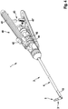
- Fig. 1a an embodiment of a medical instrument according to the invention is shown in a partially cutaway view, wherein only a distal end portion is shown.
- the medical instrument 1 comprises an elongate, for insertion in a body cavity of a human or animal body suitable shaft 2, which comprises a distal end portion 3 and a proximal portion 4, wherein from the proximal portion 4 of the shaft in Fig. 1a only the distal end is shown.
- the medical instrument 1 comprises a tool 5 which is arranged at the distal end of the distal end section 3 of the shaft 2.
- the tool 5 comprises two jaw parts 6, 7, of which a first jaw part 6 is pivotally mounted on a main part 8 of the tool 5 and a second jaw part 7 is rigidly connected to the main part 8.
- the jaw parts 6, 7 are formed in the illustrated embodiment for gripping and holding a surgical needle. On the insides of the jaw parts 6, 7, for example, parallel grooves may be arranged for the secure holding of a surgical needle.
- the pivot axis 9 of the pivotable jaw part 6 extends transversely to a longitudinal axis of the distal end portion 3 of the shaft 2.
- the main part 8 is rotatably mounted with a pivot bearing 10 relative to an outer tube 11 of the distal end portion 3 of the shaft 2 about the longitudinal axis of the distal end portion 3.
- the outer tube 11 is fixedly connected at the proximal end to a joint part 12, which is mounted pivotably around a transverse axis at the distal end region of an outer tube 13 of the proximal section 4 of the shaft 2.
- Fig. 1a is the pivot axis about which the distal end portion 3 relative to the proximal portion 4 of the shaft 2 is pivotable, perpendicular to the plane of the drawing.
- Fig. 1b shows the distal end portion of the medical instrument 1 in an axial longitudinal section, wherein the sectional plane in Fig. La is perpendicular to the plane of the drawing.
- the main part 8 with a pin 14 rotatably connected to a distal end portion 15 of a rotatable shaft.
- the distal end portion 15 of the rotatable shaft is connected via a toothing 16 to a proximal portion 17 of the rotatable shaft extending within the proximal portion 4 of the shaft 2 and via the rotation of the main part 8 and thus of the jaw parts 6 , 7 can be effected about the longitudinal axis of the distal end portion 3 of the shaft 2.
- a guide sleeve 20 is arranged, which is fixedly connected to the main part 8 and whose function is described in more detail below.
- a tension sleeve 21 is mounted, which receives the distal end portion 15 of the rotatable shaft and slides on this.
- the tension sleeve 21 is coupled on the distal side to the pivotable jaw part 6 such that an axial displacement of the tension sleeve 21 in the distal direction causes opening of the jaw part 6 and an axial displacement in the proximal direction causes the jaw part 6 to close.
- the tension sleeve 21 is connected via a pivot bearing 22 with an axially displaceable intermediate piece 23, which in turn is connected via a connecting lever 24 with a running on or in the proximal portion 4 of the shaft 2 pull rod (s. Fig. 1a ).
- the pull rod, the connecting lever 24, the intermediate piece 23, the swivel joint 22 and the tension sleeve 21 form a first transmission element, by the axial displacement of the movement of the movable jaw part 6 for opening and closing the forceps jaw formed by the jaws 6, 7 from the proximal end of Shaft 2 ago can be controlled.
- the locking elements 25, 25 ' are connected to an annular, longitudinally displaceably mounted on the tension sleeve 21 locking slide 27.
- the locking slide 27 is rotatably connected via a pivot bearing 28 with an intermediate piece 29, which is connected via a connecting lever 30 with a push rod which runs on or in the proximal portion 4 of the shaft 2 (s. Fig. 1a ).
- This push rod, together with the connecting lever 30, the intermediate piece 29, the pivot bearing 28 and the locking slide 27 is a second transmission element, through which an axial displacement of the locking elements 25, 25 'from the proximal end of the shaft 2 can be effected.
- the tension sleeve 21 has on its outer side two inclined surfaces 31, 31 ', each radially increasing in the proximal direction, ie the distance from the longitudinal axis of the tension sleeve 21 and the distal end portion 3 of the shaft 2 increases in the proximal direction
- the guide sleeve 20 has on its inside two counter-surfaces 32, 32 ', which are each opposite the surfaces 31, 31' are arranged.
- the mating surfaces 32, 32 ' also increase in the proximal direction.
- the angle of inclination the counter surfaces 32, 32 'to the longitudinal axis greater than the inclination angle of the inclined surfaces 31, 31'.
- FIGS. 2a and 2b is the distal portion of the medical instrument 1 as in Figs FIGS. 1a and 1b shown, however, the forceps jaw is in Fig. 2a and 2b closed.
- the closed position can be held between the jaws 6, 7, for example, a surgical needle (not shown).
- the tension sleeve 21 relative to the position with the jaw part 6 open (s. Fig. 1a, 1b ) in the proximal direction.
- the pull rod extending in or on the proximal section 4 of the shaft 2 has been pulled proximally, as a result of which the tension sleeve 21 has been displaced via the connecting lever 24, the intermediate piece 23 and the pivot bearing 22.
- the oblique surfaces 31, 31 ' now each such opposite to the inclined mating surfaces 32, 32' arranged that between these a larger gap is formed. Since the angle of inclination of the mating surfaces 32, 32 'is greater than that of the inclined surfaces 31, 31', the space in the in Fig. 2b shown axial longitudinal section on a wedge-shaped shape. The spaces are at the in Fig.
- FIG. 2b shown position of the tension sleeve 21 wide enough to each receive a locking element 25, 25 '.
- the locking slide 27 has been displaced in the distal direction. This can be effected by corresponding actuation of the push rod extending in or on the proximal section 4 of the shaft 2, which controls a corresponding axial displacement of the locking slide 27 via the connecting lever 30, the intermediate piece 29 and the pivot bearing 28.
- the locking slide 27 in turn displaces the locking elements 25, 25 'in the distal direction.
- the force to move the push rod distally and for moving the locking elements 25, 25 'in the interstices is characterized by a in a handle of the instrument (s. Fig. 4 ) applied control spring applied.
- the locking elements 25, 25 ' have a wedge shape at least in their distal region, wherein the wedge angle corresponds approximately to the opening angle of the intermediate space formed between the inclined surfaces 31, 31' and the respective mating surfaces 32, 32 '.
- the locking elements 25, 25 ' can be moved so far in the distal direction until they abut the respective oblique surface 31, 31' of the tension sleeve 21 and at the same time on the respective mating surface 32, 32 'of the guide sleeve 20; As a result, a distal stop for the movement of the locking elements 25, 25 'is achieved.
- the locking elements 25, 25 ' are so movably connected to the locking slide 27 that they can follow the oblique surfaces 31, 31' and the mating surfaces 32, 32 'to the two-sided concerns when inserted into the spaces. In this state, an axial displacement of the tension sleeve 21 in the distal direction is no longer possible because it is blocked by the locking elements 25, 25 '.
- the inclination angle of the inclined surfaces 31, 31 'and the mating surfaces 32, 32' are chosen such that a self-locking occurs, whereby a displacement of the tension sleeve 21 in the proximal direction is prevented.
- the oblique surfaces 31, 31 ' are inclined for this purpose by about 5 ° to 6 ° against the displacement direction of the tension sleeve 21, which is directed parallel to the longitudinal axis of the distal end portion 3 of the shaft 2, and the counter surfaces 32, 32' are about 10 ° inclined to 12 ° to the longitudinal axis.
- the movable jaw part 6 is thus locked in a self-locking manner, and a surgical needle held between the jaw parts 6, 7 is held firmly, without a user having to continue to exert a force for this purpose.
- the locking elements 25, 25 ', as well as the tension sleeve 21 and the guide sleeve 20, are made for example of stainless steel, wherein the locking elements 25, 25' and the surfaces 31, 31 'and the mating surfaces 32, 32' are preferably hardened.
- the jaws can be easily rotated by applying a torsional force on the rotatable shaft 15, 17. Also, the pivot bearings 22, 28 of the first and second transmission element are relieved and do not hinder the rotation. Furthermore, the distal end portion 3 of the shaft 2 can be pivoted freely relative to the proximal portion 4 of the shaft 2.
- the tension sleeve 21 is acted upon by the first transmission element again with tensile force.
- the clamping force is taken from the locking elements 25, 25 ', which can now be pulled out of the spaces controlled by the handle via the second transmission element.
- the tension sleeve 21 can move freely when the locking elements 25, 25 'are withdrawn, the jaw part 6 can be opened by means of the first transmission element, and the needle can be released from the jaw parts 6, 7.
- Fig. 3 are shown in the manner of an exploded view, the tension sleeve 21, the guide sleeve 20 and a locking element 25.
- the tension sleeve 21 is formed substantially cylindrical and has a continuous inner cavity 33 for receiving the distal end portion 15 of the rotatable shaft (s. Fig. 1b ).
- the tension sleeve 21 has a distal extension 34 which carries pins 35, 35 ', which engage in recesses of a fork-shaped extension of the pivotable jaw part 6 in order to pivot the jaw part 6 by axial displacement of the tension sleeve 21.
- On the outside of the tension sleeve 21 two flat inclined surfaces 31, 31 'are arranged on opposite sides.
- the guide sleeve 20 is substantially formed as a cylindrical tube which carries on its inside two mutually opposite grooves 36, 36 ', in which the locking elements 25, 25' are guided.
- the respective bottom of the grooves 36, 36 ' forms the oblique mating surfaces 32, 32'. These are each flat surfaces in the illustrated embodiment.
- the tension sleeve 21 is received longitudinally displaceable within the guide sleeve 20, wherein the tension sleeve 21 is rotatably connected by the engagement of the extension 34 in the recess 37 of the guide sleeve 20 and at one of the distal portion 15 of the rotatable shaft and the pin 14 mediated rotation of the main part 8 is rotated by this.
- the oblique surfaces 31, 31 'on the outside of the tension sleeve 21 are arranged opposite the grooves 36, 36' and thus opposite the counter surfaces 32, 32 '.
- the locking element 25 is received with its distal part in the groove 36 and guided in this in the longitudinal direction.
- the distal part of the locking element 25 has a wedge-shaped shape, so that the locking element 25 can be easily inserted into the groove 36 until it makes surface contact with the surface 31 and the mating surface 32.
- Proximal note carries the locking element laterally two lugs 38, 38 ', with which it is attached to the locking slide 27 (s. Fig. 1b ).
- the locking element 25 can thus be displaced in the axial direction by means of the locking slide 27 and is pivotable about the axis formed by the lugs 38, 38 '.
- the locking element 25 is sufficiently movable in the radial direction to in between the Surface 31 and the counter surface 32 formed space to penetrate defined by abutment against the surface 31 and the counter surface 32 stop.
- the axially opposite the locking element 25 arranged second locking element 25 ' is designed in the same way and guided in the groove 36'.
- Fig. 4 the medical instrument according to the described embodiment is shown in an overall view.
- the distal end portion 3 of the shaft 2 can be pivoted relative to the proximal portion 4 of the shaft 2.
- a handle 40 is arranged, which has a handle with two handle parts 41, 41 ', which are connected to the proximal end of the tie rod 46 of the first transmission element.
- the pull rod 46 can be displaced proximally, thereby moving the movable jaw member 6 toward the stationary jaw member 7 to grip about a surgical needle.
- a slider 42 is arranged, which is connected to the push rod of the second transmission element. If the needle has been gripped firmly, the movable jaw part 6 can be unlocked by displacing the slider 42 in the distal direction.
- a catch 43 is provided between the handle parts 41, 41 '.
- the handle 40 has a rotary knob 44, with which the forceps jaw can be rotated about a longitudinal axis and which is for this purpose connected to the proximal portion 17 of the rotatable shaft, and a further rotary wheel 45, with which the pivoting movement of the distal end portion 3 of the shaft 2 can be controlled.
Landscapes
- Health & Medical Sciences (AREA)
- Life Sciences & Earth Sciences (AREA)
- Surgery (AREA)
- Heart & Thoracic Surgery (AREA)
- Engineering & Computer Science (AREA)
- Biomedical Technology (AREA)
- Nuclear Medicine, Radiotherapy & Molecular Imaging (AREA)
- Medical Informatics (AREA)
- Molecular Biology (AREA)
- Animal Behavior & Ethology (AREA)
- General Health & Medical Sciences (AREA)
- Public Health (AREA)
- Veterinary Medicine (AREA)
- Ophthalmology & Optometry (AREA)
- Surgical Instruments (AREA)
Claims (14)
- Instrument médical avec une tige allongée (2) et un outil (5) disposé à une partie d'extrémité distale (3) de la tige (2), qui comprend deux éléments d'outil coopérant l'un avec l'autre en particulier pour maintenir un objet, et dont au moins un est mobile au moyen d'un premier élément de transmission déplaçable longitudinalement, caractérisé en ce qu'une partie d'extrémité distale du premier élément de transmission présente une face (31, 31') inclinée par rapport à une direction de déplacement et la partie d'extrémité distale (3) de la tige (2) ou un élément solidaire en mouvement de celle-ci présente une face opposée (32, 32') inclinée par rapport à la direction de déplacement, qui forme avec la face inclinée (31, 31') un espace intermédiaire dépendant d'un déplacement de la partie d'extrémité distale du premier élément de transmission, et en ce qu'il se trouve au moins un élément de verrouillage (25, 25'), qui est déplaçable dans l'espace intermédiaire pour le blocage du déplacement du premier élément de transmission et hors de celui-ci pour lever le blocage.
- Instrument médical selon la revendication 1, caractérisé en ce que la face inclinée (31, 31') est disposée sur un côté extérieur de la partie d'extrémité distale du premier élément de transmission et la face opposée (32, 32') est disposée sur un côté intérieur d'un élément tubulaire.
- Instrument médical selon la revendication 1 ou 2, caractérisé en ce que les éléments d'outil coopérant l'un avec l'autre peuvent être fermés par un déplacement du premier élément de transmission dans une direction proximale et en ce que la face inclinée (31, 31') et la face opposée (32, 32') sont radialement ascendantes en direction proximale.
- Instrument médical selon l'une quelconque des revendications précédentes, caractérisé en ce que l'espace intermédiaire est réalisé en forme de coin.
- Instrument médical selon l'une quelconque des revendications précédentes, caractérisé en ce que la face inclinée (31, 31') et la face opposée (32, 32') sont inclinées par rapport à la direction de déplacement d'un angle tel que le déplacement du premier élément de transmission puisse être bloqué par auto-blocage.
- Instrument médical selon l'une quelconque des revendications précédentes, caractérisé en ce que ledit au moins un élément de verrouillage (25, 25') est réalisé en forme de coin.
- Instrument médical selon l'une quelconque des revendications précédentes, caractérisé en ce que ledit au moins un élément de verrouillage (25, 25') est assemblé de façon déplaçable radialement à une partie d'extrémité distale d'un deuxième élément de transmission.
- Instrument médical selon la revendication 7, caractérisé en ce que ledit au moins un élément de verrouillage (25, 25') est suspendu avec deux ergots (38, 38') à la partie d'extrémité distale du deuxième élément de transmission.
- Instrument médical selon l'une quelconque des revendications précédentes, caractérisé en ce que ledit au moins un élément de verrouillage (25, 25') est guidé de façon déplaçable dans une rainure (36, 36') de la partie d'extrémité distale (3) de la tige (2), dans lequel un fond de la rainure (36, 36') forme la face opposée (32, 32').
- Instrument médical selon l'une quelconque des revendications précédentes, caractérisé en ce qu'il se trouve deux éléments de verrouillage (25, 25'), qui sont déplaçables ensemble.
- Instrument médical selon l'une quelconque des revendications précédentes, caractérisé en ce que l'outil (5) peut tourner autour d'un axe de rotation parallèle à un axe longitudinal de la partie d'extrémité distale (3) de la tige (2) et la partie d'extrémité distale du premier élément de transmission est montée de façon rotative autour de l'axe de rotation par rapport à une partie proximale.
- Instrument médical selon l'une quelconque des revendications précédentes, caractérisé en ce que la partie d'extrémité distale (3) de la tige (2) peut pivoter autour d'un axe transversal par rapport à une partie proximale (4) de la tige (2).
- Instrument médical selon l'une quelconque des revendications précédentes, caractérisé en ce que ledit au moins un élément de verrouillage (25, 25') est chargé par un ressort dans une position de verrouillage.
- Instrument médical selon la revendication 13, caractérisé en ce qu'un ressort de commande pour la mise en charge élastique dudit au moins un élément de verrouillage est disposé dans une poignée (40) de l'instrument médical.
Applications Claiming Priority (1)
| Application Number | Priority Date | Filing Date | Title |
|---|---|---|---|
| DE102016103640.4A DE102016103640A1 (de) | 2016-03-01 | 2016-03-01 | Medizinisches Instrument |
Publications (2)
| Publication Number | Publication Date |
|---|---|
| EP3213700A1 EP3213700A1 (fr) | 2017-09-06 |
| EP3213700B1 true EP3213700B1 (fr) | 2018-10-24 |
Family
ID=58098428
Family Applications (1)
| Application Number | Title | Priority Date | Filing Date |
|---|---|---|---|
| EP17155947.9A Active EP3213700B1 (fr) | 2016-03-01 | 2017-02-14 | Instrument médical |
Country Status (3)
| Country | Link |
|---|---|
| US (1) | US10342560B2 (fr) |
| EP (1) | EP3213700B1 (fr) |
| DE (1) | DE102016103640A1 (fr) |
Families Citing this family (5)
| Publication number | Priority date | Publication date | Assignee | Title |
|---|---|---|---|---|
| EP2792319B1 (fr) * | 2013-04-17 | 2020-10-21 | JakuTec Medizintechnik GmbH & Co. KG | Élément d'actionnement et paire de bascules pour un élément d'actionnement |
| DE102016103640A1 (de) * | 2016-03-01 | 2017-09-07 | Karl Storz Gmbh & Co. Kg | Medizinisches Instrument |
| CN108325069B (zh) * | 2018-04-20 | 2024-11-26 | 北京品驰医疗设备股份有限公司 | 一种医疗器械固定装置 |
| DE102020119462A1 (de) | 2020-07-23 | 2022-01-27 | Karl Storz Se & Co. Kg | Medizinisches instrument |
| DE102023134397A1 (de) * | 2023-12-08 | 2025-06-12 | Aesculap Ag | Chirurgisches minimalinvasive Instrument |
Family Cites Families (8)
| Publication number | Priority date | Publication date | Assignee | Title |
|---|---|---|---|---|
| US5626607A (en) * | 1995-04-03 | 1997-05-06 | Heartport, Inc. | Clamp assembly and method of use |
| DE602006009914D1 (de) | 2006-06-29 | 2009-12-03 | Univ Dundee | Medizinisches Instrument zum Greifen eines Objektes, insbesondere Nadelhalter |
| DE102009055747A1 (de) | 2009-11-26 | 2011-06-09 | Olympus Winter & Ibe Gmbh | Chirurgische Zange mit Nuteingriff |
| EP2522280B1 (fr) | 2011-05-11 | 2016-03-02 | University Of Dundee | Instrument médical pour la préhension d'un objet, en particulier un porte-aiguille |
| DE102011081464A1 (de) * | 2011-08-24 | 2013-02-28 | Karl Storz Gmbh & Co. Kg | Werkzeug für ein mikroinvasiv-chirurgisches Instrument |
| DE102015015655A1 (de) | 2015-12-01 | 2017-06-01 | Karl Storz Gmbh & Co. Kg | Medizinisches Instrument |
| DE102015015664A1 (de) | 2015-12-01 | 2017-06-14 | Karl Storz Gmbh & Co. Kg | Medizinisches Instrument |
| DE102016103640A1 (de) * | 2016-03-01 | 2017-09-07 | Karl Storz Gmbh & Co. Kg | Medizinisches Instrument |
-
2016
- 2016-03-01 DE DE102016103640.4A patent/DE102016103640A1/de not_active Withdrawn
-
2017
- 2017-02-14 EP EP17155947.9A patent/EP3213700B1/fr active Active
- 2017-02-24 US US15/441,384 patent/US10342560B2/en active Active
Non-Patent Citations (1)
| Title |
|---|
| None * |
Also Published As
| Publication number | Publication date |
|---|---|
| EP3213700A1 (fr) | 2017-09-06 |
| DE102016103640A1 (de) | 2017-09-07 |
| US10342560B2 (en) | 2019-07-09 |
| US20170252053A1 (en) | 2017-09-07 |
Similar Documents
| Publication | Publication Date | Title |
|---|---|---|
| EP2510888B1 (fr) | Dispositif de manipulation pour un instrument de chirurgie micro-invasive | |
| EP1014879B1 (fr) | Tournevis medical | |
| DE19707373C1 (de) | Bajonettkupplung zum lösbaren Verbinden zweier Rohrschaftinstrumente oder -instrumententeile | |
| EP0645127B1 (fr) | Outil à choc pour extraction d'une prothèse de hanche | |
| EP3213700B1 (fr) | Instrument médical | |
| EP3410965B1 (fr) | Instrument pour guider une tige dans un logement d'implant | |
| DE20007177U1 (de) | Medizinisches Instrument mit sperrbarem Kraftübertragungselement | |
| EP1082061A1 (fr) | Poignee pour un instrument medical a tige creuse | |
| EP2510889B1 (fr) | Dispositif de manipulation pour un instrument de chirurgie micro-invasive | |
| EP3351192A2 (fr) | Instrument chirurgical, en particulier pour la neurochirurgie | |
| EP1905369B1 (fr) | Tournevis pour la manipulation d'une vis dans un corps humain ou animal | |
| WO2011063892A1 (fr) | Pince chirurgicale à système d'engagement dans une rainure | |
| EP4054447B1 (fr) | Instrument médical à tige coulissante | |
| EP2702950A1 (fr) | Système d'outil médical, ainsi que poignée et outil pour un système d'outil médical | |
| EP2785262B1 (fr) | Poignée chirurgicale et instrument chirurgical à tige tubulaire doté d'une poignée chirurgicale | |
| EP1365691B1 (fr) | Instrument medical | |
| DE202011052176U1 (de) | Chirurgischer Handgriff sowie chirurgisches Rohrschaftinstrument mit einem chirurgischen Handgriff | |
| DE202009003255U1 (de) | Trokarführungshülse und Trokarsystem | |
| DE102006016214A1 (de) | Chirurgischer Instrumentengriff und chirurgisches Instrument | |
| DE202007000427U1 (de) | Chirurgischer Haltegriff und chirurgisches Instrument | |
| EP3943024B1 (fr) | Instrument médical | |
| EP1941840B1 (fr) | Instrument chirurgical | |
| DE102016101822A1 (de) | Instrument zum Führen eines Stabs in eine Implantataufnahme | |
| DE102007001749B4 (de) | Chirurigsches Instrument | |
| DE202006005632U1 (de) | Chirurgischer Instrumentengriff und chirurgisches Instrument |
Legal Events
| Date | Code | Title | Description |
|---|---|---|---|
| PUAI | Public reference made under article 153(3) epc to a published international application that has entered the european phase |
Free format text: ORIGINAL CODE: 0009012 |
|
| STAA | Information on the status of an ep patent application or granted ep patent |
Free format text: STATUS: THE APPLICATION HAS BEEN PUBLISHED |
|
| AK | Designated contracting states |
Kind code of ref document: A1 Designated state(s): AL AT BE BG CH CY CZ DE DK EE ES FI FR GB GR HR HU IE IS IT LI LT LU LV MC MK MT NL NO PL PT RO RS SE SI SK SM TR |
|
| AX | Request for extension of the european patent |
Extension state: BA ME |
|
| RAP1 | Party data changed (applicant data changed or rights of an application transferred) |
Owner name: KARL STORZ SE & CO. KG |
|
| STAA | Information on the status of an ep patent application or granted ep patent |
Free format text: STATUS: REQUEST FOR EXAMINATION WAS MADE |
|
| 17P | Request for examination filed |
Effective date: 20180301 |
|
| RBV | Designated contracting states (corrected) |
Designated state(s): AL AT BE BG CH CY CZ DE DK EE ES FI FR GB GR HR HU IE IS IT LI LT LU LV MC MK MT NL NO PL PT RO RS SE SI SK SM TR |
|
| GRAP | Despatch of communication of intention to grant a patent |
Free format text: ORIGINAL CODE: EPIDOSNIGR1 |
|
| STAA | Information on the status of an ep patent application or granted ep patent |
Free format text: STATUS: GRANT OF PATENT IS INTENDED |
|
| INTG | Intention to grant announced |
Effective date: 20180718 |
|
| GRAS | Grant fee paid |
Free format text: ORIGINAL CODE: EPIDOSNIGR3 |
|
| GRAA | (expected) grant |
Free format text: ORIGINAL CODE: 0009210 |
|
| STAA | Information on the status of an ep patent application or granted ep patent |
Free format text: STATUS: THE PATENT HAS BEEN GRANTED |
|
| AK | Designated contracting states |
Kind code of ref document: B1 Designated state(s): AL AT BE BG CH CY CZ DE DK EE ES FI FR GB GR HR HU IE IS IT LI LT LU LV MC MK MT NL NO PL PT RO RS SE SI SK SM TR |
|
| REG | Reference to a national code |
Ref country code: CH Ref legal event code: EP |
|
| REG | Reference to a national code |
Ref country code: IE Ref legal event code: FG4D Free format text: LANGUAGE OF EP DOCUMENT: GERMAN |
|
| REG | Reference to a national code |
Ref country code: AT Ref legal event code: REF Ref document number: 1055750 Country of ref document: AT Kind code of ref document: T Effective date: 20181115 |
|
| REG | Reference to a national code |
Ref country code: DE Ref legal event code: R096 Ref document number: 502017000275 Country of ref document: DE |
|
| REG | Reference to a national code |
Ref country code: NL Ref legal event code: MP Effective date: 20181024 |
|
| REG | Reference to a national code |
Ref country code: LT Ref legal event code: MG4D |
|
| PG25 | Lapsed in a contracting state [announced via postgrant information from national office to epo] |
Ref country code: NL Free format text: LAPSE BECAUSE OF FAILURE TO SUBMIT A TRANSLATION OF THE DESCRIPTION OR TO PAY THE FEE WITHIN THE PRESCRIBED TIME-LIMIT Effective date: 20181024 |
|
| PG25 | Lapsed in a contracting state [announced via postgrant information from national office to epo] |
Ref country code: LV Free format text: LAPSE BECAUSE OF FAILURE TO SUBMIT A TRANSLATION OF THE DESCRIPTION OR TO PAY THE FEE WITHIN THE PRESCRIBED TIME-LIMIT Effective date: 20181024 Ref country code: HR Free format text: LAPSE BECAUSE OF FAILURE TO SUBMIT A TRANSLATION OF THE DESCRIPTION OR TO PAY THE FEE WITHIN THE PRESCRIBED TIME-LIMIT Effective date: 20181024 Ref country code: BG Free format text: LAPSE BECAUSE OF FAILURE TO SUBMIT A TRANSLATION OF THE DESCRIPTION OR TO PAY THE FEE WITHIN THE PRESCRIBED TIME-LIMIT Effective date: 20190124 Ref country code: NO Free format text: LAPSE BECAUSE OF FAILURE TO SUBMIT A TRANSLATION OF THE DESCRIPTION OR TO PAY THE FEE WITHIN THE PRESCRIBED TIME-LIMIT Effective date: 20190124 Ref country code: PL Free format text: LAPSE BECAUSE OF FAILURE TO SUBMIT A TRANSLATION OF THE DESCRIPTION OR TO PAY THE FEE WITHIN THE PRESCRIBED TIME-LIMIT Effective date: 20181024 Ref country code: ES Free format text: LAPSE BECAUSE OF FAILURE TO SUBMIT A TRANSLATION OF THE DESCRIPTION OR TO PAY THE FEE WITHIN THE PRESCRIBED TIME-LIMIT Effective date: 20181024 Ref country code: LT Free format text: LAPSE BECAUSE OF FAILURE TO SUBMIT A TRANSLATION OF THE DESCRIPTION OR TO PAY THE FEE WITHIN THE PRESCRIBED TIME-LIMIT Effective date: 20181024 Ref country code: IS Free format text: LAPSE BECAUSE OF FAILURE TO SUBMIT A TRANSLATION OF THE DESCRIPTION OR TO PAY THE FEE WITHIN THE PRESCRIBED TIME-LIMIT Effective date: 20190224 Ref country code: FI Free format text: LAPSE BECAUSE OF FAILURE TO SUBMIT A TRANSLATION OF THE DESCRIPTION OR TO PAY THE FEE WITHIN THE PRESCRIBED TIME-LIMIT Effective date: 20181024 |
|
| PG25 | Lapsed in a contracting state [announced via postgrant information from national office to epo] |
Ref country code: GR Free format text: LAPSE BECAUSE OF FAILURE TO SUBMIT A TRANSLATION OF THE DESCRIPTION OR TO PAY THE FEE WITHIN THE PRESCRIBED TIME-LIMIT Effective date: 20190125 Ref country code: SE Free format text: LAPSE BECAUSE OF FAILURE TO SUBMIT A TRANSLATION OF THE DESCRIPTION OR TO PAY THE FEE WITHIN THE PRESCRIBED TIME-LIMIT Effective date: 20181024 Ref country code: RS Free format text: LAPSE BECAUSE OF FAILURE TO SUBMIT A TRANSLATION OF THE DESCRIPTION OR TO PAY THE FEE WITHIN THE PRESCRIBED TIME-LIMIT Effective date: 20181024 Ref country code: PT Free format text: LAPSE BECAUSE OF FAILURE TO SUBMIT A TRANSLATION OF THE DESCRIPTION OR TO PAY THE FEE WITHIN THE PRESCRIBED TIME-LIMIT Effective date: 20190224 Ref country code: AL Free format text: LAPSE BECAUSE OF FAILURE TO SUBMIT A TRANSLATION OF THE DESCRIPTION OR TO PAY THE FEE WITHIN THE PRESCRIBED TIME-LIMIT Effective date: 20181024 |
|
| REG | Reference to a national code |
Ref country code: DE Ref legal event code: R097 Ref document number: 502017000275 Country of ref document: DE |
|
| PG25 | Lapsed in a contracting state [announced via postgrant information from national office to epo] |
Ref country code: DK Free format text: LAPSE BECAUSE OF FAILURE TO SUBMIT A TRANSLATION OF THE DESCRIPTION OR TO PAY THE FEE WITHIN THE PRESCRIBED TIME-LIMIT Effective date: 20181024 Ref country code: CZ Free format text: LAPSE BECAUSE OF FAILURE TO SUBMIT A TRANSLATION OF THE DESCRIPTION OR TO PAY THE FEE WITHIN THE PRESCRIBED TIME-LIMIT Effective date: 20181024 |
|
| PG25 | Lapsed in a contracting state [announced via postgrant information from national office to epo] |
Ref country code: RO Free format text: LAPSE BECAUSE OF FAILURE TO SUBMIT A TRANSLATION OF THE DESCRIPTION OR TO PAY THE FEE WITHIN THE PRESCRIBED TIME-LIMIT Effective date: 20181024 Ref country code: SK Free format text: LAPSE BECAUSE OF FAILURE TO SUBMIT A TRANSLATION OF THE DESCRIPTION OR TO PAY THE FEE WITHIN THE PRESCRIBED TIME-LIMIT Effective date: 20181024 Ref country code: EE Free format text: LAPSE BECAUSE OF FAILURE TO SUBMIT A TRANSLATION OF THE DESCRIPTION OR TO PAY THE FEE WITHIN THE PRESCRIBED TIME-LIMIT Effective date: 20181024 Ref country code: SM Free format text: LAPSE BECAUSE OF FAILURE TO SUBMIT A TRANSLATION OF THE DESCRIPTION OR TO PAY THE FEE WITHIN THE PRESCRIBED TIME-LIMIT Effective date: 20181024 |
|
| PLBE | No opposition filed within time limit |
Free format text: ORIGINAL CODE: 0009261 |
|
| STAA | Information on the status of an ep patent application or granted ep patent |
Free format text: STATUS: NO OPPOSITION FILED WITHIN TIME LIMIT |
|
| 26N | No opposition filed |
Effective date: 20190725 |
|
| PG25 | Lapsed in a contracting state [announced via postgrant information from national office to epo] |
Ref country code: SI Free format text: LAPSE BECAUSE OF FAILURE TO SUBMIT A TRANSLATION OF THE DESCRIPTION OR TO PAY THE FEE WITHIN THE PRESCRIBED TIME-LIMIT Effective date: 20181024 Ref country code: LU Free format text: LAPSE BECAUSE OF NON-PAYMENT OF DUE FEES Effective date: 20190214 Ref country code: MC Free format text: LAPSE BECAUSE OF FAILURE TO SUBMIT A TRANSLATION OF THE DESCRIPTION OR TO PAY THE FEE WITHIN THE PRESCRIBED TIME-LIMIT Effective date: 20181024 |
|
| REG | Reference to a national code |
Ref country code: BE Ref legal event code: MM Effective date: 20190228 |
|
| REG | Reference to a national code |
Ref country code: IE Ref legal event code: MM4A |
|
| PG25 | Lapsed in a contracting state [announced via postgrant information from national office to epo] |
Ref country code: IE Free format text: LAPSE BECAUSE OF NON-PAYMENT OF DUE FEES Effective date: 20190214 |
|
| PG25 | Lapsed in a contracting state [announced via postgrant information from national office to epo] |
Ref country code: BE Free format text: LAPSE BECAUSE OF NON-PAYMENT OF DUE FEES Effective date: 20190228 |
|
| PG25 | Lapsed in a contracting state [announced via postgrant information from national office to epo] |
Ref country code: TR Free format text: LAPSE BECAUSE OF FAILURE TO SUBMIT A TRANSLATION OF THE DESCRIPTION OR TO PAY THE FEE WITHIN THE PRESCRIBED TIME-LIMIT Effective date: 20181024 |
|
| PG25 | Lapsed in a contracting state [announced via postgrant information from national office to epo] |
Ref country code: MT Free format text: LAPSE BECAUSE OF FAILURE TO SUBMIT A TRANSLATION OF THE DESCRIPTION OR TO PAY THE FEE WITHIN THE PRESCRIBED TIME-LIMIT Effective date: 20181024 |
|
| REG | Reference to a national code |
Ref country code: CH Ref legal event code: PL |
|
| PG25 | Lapsed in a contracting state [announced via postgrant information from national office to epo] |
Ref country code: CH Free format text: LAPSE BECAUSE OF NON-PAYMENT OF DUE FEES Effective date: 20200229 Ref country code: LI Free format text: LAPSE BECAUSE OF NON-PAYMENT OF DUE FEES Effective date: 20200229 |
|
| PG25 | Lapsed in a contracting state [announced via postgrant information from national office to epo] |
Ref country code: CY Free format text: LAPSE BECAUSE OF FAILURE TO SUBMIT A TRANSLATION OF THE DESCRIPTION OR TO PAY THE FEE WITHIN THE PRESCRIBED TIME-LIMIT Effective date: 20181024 |
|
| PG25 | Lapsed in a contracting state [announced via postgrant information from national office to epo] |
Ref country code: HU Free format text: LAPSE BECAUSE OF FAILURE TO SUBMIT A TRANSLATION OF THE DESCRIPTION OR TO PAY THE FEE WITHIN THE PRESCRIBED TIME-LIMIT; INVALID AB INITIO Effective date: 20170214 |
|
| PG25 | Lapsed in a contracting state [announced via postgrant information from national office to epo] |
Ref country code: MK Free format text: LAPSE BECAUSE OF FAILURE TO SUBMIT A TRANSLATION OF THE DESCRIPTION OR TO PAY THE FEE WITHIN THE PRESCRIBED TIME-LIMIT Effective date: 20181024 |
|
| REG | Reference to a national code |
Ref country code: AT Ref legal event code: MM01 Ref document number: 1055750 Country of ref document: AT Kind code of ref document: T Effective date: 20220214 |
|
| PG25 | Lapsed in a contracting state [announced via postgrant information from national office to epo] |
Ref country code: AT Free format text: LAPSE BECAUSE OF NON-PAYMENT OF DUE FEES Effective date: 20220214 |
|
| P01 | Opt-out of the competence of the unified patent court (upc) registered |
Effective date: 20230527 |
|
| PGFP | Annual fee paid to national office [announced via postgrant information from national office to epo] |
Ref country code: FR Payment date: 20250224 Year of fee payment: 9 |
|
| PGFP | Annual fee paid to national office [announced via postgrant information from national office to epo] |
Ref country code: IT Payment date: 20250225 Year of fee payment: 9 Ref country code: GB Payment date: 20250218 Year of fee payment: 9 |
|
| PGFP | Annual fee paid to national office [announced via postgrant information from national office to epo] |
Ref country code: DE Payment date: 20260220 Year of fee payment: 10 |