EP3213819B1 - Dispositif et méthode de séparation - Google Patents
Dispositif et méthode de séparation Download PDFInfo
- Publication number
- EP3213819B1 EP3213819B1 EP16158300.0A EP16158300A EP3213819B1 EP 3213819 B1 EP3213819 B1 EP 3213819B1 EP 16158300 A EP16158300 A EP 16158300A EP 3213819 B1 EP3213819 B1 EP 3213819B1
- Authority
- EP
- European Patent Office
- Prior art keywords
- liquid waste
- waste container
- vessels
- liquid
- tip holder
- Prior art date
- Legal status (The legal status is an assumption and is not a legal conclusion. Google has not performed a legal analysis and makes no representation as to the accuracy of the status listed.)
- Active
Links
Images




Classifications
-
- G—PHYSICS
- G01—MEASURING; TESTING
- G01N—INVESTIGATING OR ANALYSING MATERIALS BY DETERMINING THEIR CHEMICAL OR PHYSICAL PROPERTIES
- G01N1/00—Sampling; Preparing specimens for investigation
- G01N1/28—Preparing specimens for investigation including physical details of (bio-)chemical methods covered elsewhere, e.g. G01N33/50, C12Q
- G01N1/40—Concentrating samples
- G01N1/405—Concentrating samples by adsorption or absorption
-
- C—CHEMISTRY; METALLURGY
- C12—BIOCHEMISTRY; BEER; SPIRITS; WINE; VINEGAR; MICROBIOLOGY; ENZYMOLOGY; MUTATION OR GENETIC ENGINEERING
- C12N—MICROORGANISMS OR ENZYMES; COMPOSITIONS THEREOF; PROPAGATING, PRESERVING, OR MAINTAINING MICROORGANISMS; MUTATION OR GENETIC ENGINEERING; CULTURE MEDIA
- C12N15/00—Mutation or genetic engineering; DNA or RNA concerning genetic engineering, vectors, e.g. plasmids, or their isolation, preparation or purification; Use of hosts therefor
- C12N15/09—Recombinant DNA-technology
- C12N15/10—Processes for the isolation, preparation or purification of DNA or RNA
- C12N15/1003—Extracting or separating nucleic acids from biological samples, e.g. pure separation or isolation methods; Conditions, buffers or apparatuses therefor
- C12N15/1006—Extracting or separating nucleic acids from biological samples, e.g. pure separation or isolation methods; Conditions, buffers or apparatuses therefor by means of a solid support carrier, e.g. particles, polymers
- C12N15/1013—Extracting or separating nucleic acids from biological samples, e.g. pure separation or isolation methods; Conditions, buffers or apparatuses therefor by means of a solid support carrier, e.g. particles, polymers by using magnetic beads
-
- B—PERFORMING OPERATIONS; TRANSPORTING
- B01—PHYSICAL OR CHEMICAL PROCESSES OR APPARATUS IN GENERAL
- B01L—CHEMICAL OR PHYSICAL LABORATORY APPARATUS FOR GENERAL USE
- B01L9/00—Supporting devices; Holding devices
- B01L9/52—Supports specially adapted for flat sample carriers, e.g. for plates, slides, chips
- B01L9/523—Supports specially adapted for flat sample carriers, e.g. for plates, slides, chips for multisample carriers, e.g. used for microtitration plates
-
- B—PERFORMING OPERATIONS; TRANSPORTING
- B01—PHYSICAL OR CHEMICAL PROCESSES OR APPARATUS IN GENERAL
- B01L—CHEMICAL OR PHYSICAL LABORATORY APPARATUS FOR GENERAL USE
- B01L9/00—Supporting devices; Holding devices
- B01L9/54—Supports specially adapted for pipettes and burettes
- B01L9/543—Supports specially adapted for pipettes and burettes for disposable pipette tips, e.g. racks or cassettes
-
- B—PERFORMING OPERATIONS; TRANSPORTING
- B03—SEPARATION OF SOLID MATERIALS USING LIQUIDS OR USING PNEUMATIC TABLES OR JIGS; MAGNETIC OR ELECTROSTATIC SEPARATION OF SOLID MATERIALS FROM SOLID MATERIALS OR FLUIDS; SEPARATION BY HIGH-VOLTAGE ELECTRIC FIELDS
- B03C—MAGNETIC OR ELECTROSTATIC SEPARATION OF SOLID MATERIALS FROM SOLID MATERIALS OR FLUIDS; SEPARATION BY HIGH-VOLTAGE ELECTRIC FIELDS
- B03C1/00—Magnetic separation
- B03C1/005—Pretreatment specially adapted for magnetic separation
- B03C1/01—Pretreatment specially adapted for magnetic separation by addition of magnetic adjuvants
-
- B—PERFORMING OPERATIONS; TRANSPORTING
- B03—SEPARATION OF SOLID MATERIALS USING LIQUIDS OR USING PNEUMATIC TABLES OR JIGS; MAGNETIC OR ELECTROSTATIC SEPARATION OF SOLID MATERIALS FROM SOLID MATERIALS OR FLUIDS; SEPARATION BY HIGH-VOLTAGE ELECTRIC FIELDS
- B03C—MAGNETIC OR ELECTROSTATIC SEPARATION OF SOLID MATERIALS FROM SOLID MATERIALS OR FLUIDS; SEPARATION BY HIGH-VOLTAGE ELECTRIC FIELDS
- B03C1/00—Magnetic separation
- B03C1/02—Magnetic separation acting directly on the substance being separated
-
- C—CHEMISTRY; METALLURGY
- C12—BIOCHEMISTRY; BEER; SPIRITS; WINE; VINEGAR; MICROBIOLOGY; ENZYMOLOGY; MUTATION OR GENETIC ENGINEERING
- C12N—MICROORGANISMS OR ENZYMES; COMPOSITIONS THEREOF; PROPAGATING, PRESERVING, OR MAINTAINING MICROORGANISMS; MUTATION OR GENETIC ENGINEERING; CULTURE MEDIA
- C12N15/00—Mutation or genetic engineering; DNA or RNA concerning genetic engineering, vectors, e.g. plasmids, or their isolation, preparation or purification; Use of hosts therefor
- C12N15/09—Recombinant DNA-technology
- C12N15/10—Processes for the isolation, preparation or purification of DNA or RNA
- C12N15/1003—Extracting or separating nucleic acids from biological samples, e.g. pure separation or isolation methods; Conditions, buffers or apparatuses therefor
-
- C—CHEMISTRY; METALLURGY
- C12—BIOCHEMISTRY; BEER; SPIRITS; WINE; VINEGAR; MICROBIOLOGY; ENZYMOLOGY; MUTATION OR GENETIC ENGINEERING
- C12Q—MEASURING OR TESTING PROCESSES INVOLVING ENZYMES, NUCLEIC ACIDS OR MICROORGANISMS; COMPOSITIONS OR TEST PAPERS THEREFOR; PROCESSES OF PREPARING SUCH COMPOSITIONS; CONDITION-RESPONSIVE CONTROL IN MICROBIOLOGICAL OR ENZYMOLOGICAL PROCESSES
- C12Q1/00—Measuring or testing processes involving enzymes, nucleic acids or microorganisms; Compositions therefor; Processes of preparing such compositions
- C12Q1/68—Measuring or testing processes involving enzymes, nucleic acids or microorganisms; Compositions therefor; Processes of preparing such compositions involving nucleic acids
- C12Q1/6806—Preparing nucleic acids for analysis, e.g. for polymerase chain reaction [PCR] assay
-
- G—PHYSICS
- G01—MEASURING; TESTING
- G01N—INVESTIGATING OR ANALYSING MATERIALS BY DETERMINING THEIR CHEMICAL OR PHYSICAL PROPERTIES
- G01N1/00—Sampling; Preparing specimens for investigation
- G01N1/28—Preparing specimens for investigation including physical details of (bio-)chemical methods covered elsewhere, e.g. G01N33/50, C12Q
- G01N1/44—Sample treatment involving radiation, e.g. heat
-
- B—PERFORMING OPERATIONS; TRANSPORTING
- B01—PHYSICAL OR CHEMICAL PROCESSES OR APPARATUS IN GENERAL
- B01L—CHEMICAL OR PHYSICAL LABORATORY APPARATUS FOR GENERAL USE
- B01L2400/00—Moving or stopping fluids
- B01L2400/04—Moving fluids with specific forces or mechanical means
- B01L2400/0403—Moving fluids with specific forces or mechanical means specific forces
- B01L2400/043—Moving fluids with specific forces or mechanical means specific forces magnetic forces
-
- G—PHYSICS
- G01—MEASURING; TESTING
- G01N—INVESTIGATING OR ANALYSING MATERIALS BY DETERMINING THEIR CHEMICAL OR PHYSICAL PROPERTIES
- G01N35/00—Automatic analysis not limited to methods or materials provided for in any single one of groups G01N1/00 - G01N33/00; Handling materials therefor
- G01N35/0098—Automatic analysis not limited to methods or materials provided for in any single one of groups G01N1/00 - G01N33/00; Handling materials therefor involving analyte bound to insoluble magnetic carrier, e.g. using magnetic separation
-
- G—PHYSICS
- G01—MEASURING; TESTING
- G01N—INVESTIGATING OR ANALYSING MATERIALS BY DETERMINING THEIR CHEMICAL OR PHYSICAL PROPERTIES
- G01N35/00—Automatic analysis not limited to methods or materials provided for in any single one of groups G01N1/00 - G01N33/00; Handling materials therefor
- G01N35/02—Automatic analysis not limited to methods or materials provided for in any single one of groups G01N1/00 - G01N33/00; Handling materials therefor using a plurality of sample containers moved by a conveyor system past one or more treatment or analysis stations
- G01N35/028—Automatic analysis not limited to methods or materials provided for in any single one of groups G01N1/00 - G01N33/00; Handling materials therefor using a plurality of sample containers moved by a conveyor system past one or more treatment or analysis stations having reaction cells in the form of microtitration plates
Definitions
- the present invention relates to devices, systems and methods for separating an analyte from a liquid sample. Separation of analytes from liquid samples is an important step in the preparation of samples for subsequent analysis to detect the presence or absence, or to quantitate analytes in liquid or liquidified samples. Different systems exist for separating analytes from other components present in liquid samples. One such separation system is based on binding of analytes to magnetic or magnetized particles. The bound analyte can be separated from the liquid non-bound components by applying a magnetic field in a magnetic separation station. For lysis and/or elution of the bound analyte, heating may be further required.
- heating stations and separation stations comprise a receiving part for vessels which contain the liquid sample.
- vessels are commonly provided in single vessels or in integrally formed multiwell plates.
- the vessels are placed in the receiving part of the station and are removed again after separation and transfer of the separated analyte to a different vessel. After removal from the receiving part of the separation station, the vessels or multiwell plates are discarded.
- the consumables are commonly loaded and unloaded manually on the separation station. Such manual loading and unloading is cumbersome and prone to user errors. Not all consumables can be surveyed (e.g. by barcode reading) to ensure their presence and proper use.
- EP 1 839 756 A1 discloses in fig. 7 a holder (71) for a multiwell plate (41) and a row of openings (72) leading to a waste connector, which allows the waste liquid to reach an external waste container (cf. fig. 12 (75)).
- US 2002/007054 A1 discloses a nucleic acid purifying apparatus with a plurality of pipette holders, multiwell plates and a waste liquid port.
- EP 2 752 671 A2 discloses a cartridge (200) comprising a row of wells and a pipette holder.
- the present invention provides a new concept of assembling different consumables required for separation of an analyte in a magnetic separation station on a re-usable support part which can be reliably loaded and unloaded manually.
- the present invention relates to a device comprising a support part.
- the support part is configured to receive a tip holder, a liquid waste container and a multiwell plate.
- the multiwell plate comprises at least one row of vessels which comprise a closed bottom and an open top.
- the present invention also relates to a multi-part device comprising a device, said device comprising a support part, said support part being configured to receive a tip holder, a liquid waste container and a multiwell plate.
- the multiwell plate comprises at least one row of vessels and one row of openings.
- the vessels comprise a closed bottom and an open top, and the openings are aligned with the liquid waste container when said liquid waste container and the multiwell plate are mounted on said support part.
- the multi-part device further comprises a tip holder, a multiwell plate and a liquid waste container, each being configured to be received by said support part.
- the present invention further relates to a method of removing liquid waste during magnetic separation of an analyte, comprising the steps of:
- the present invention relates to a device comprising a support part.
- the support part is configured to receive a tip holder, a liquid waste container and a multiwell plate.
- the multiwell plate comprises at least one row of vessels which comprise a closed bottom and an open top, and one row of openings. The openings are aligned with the liquid waste container when said liquid waste container and said multiwell plate are mounted on said support part.
- One advantage of this device is that it permits the user to reliably load and unload consumables such as tips, liquid waste containers and multiwell plates on a separation station, because all consumables and the liquid waste are loaded or removed simply by loading or removing the device.
- the tip holder comprises one row of individually formed tip holder vessels configured to receive pipette tips, wherein said rows of vessels, said row of openings and said tip holder comprise an equal number of vessels/openings/tip holder vessels.
- said rows of vessels, rows of openings and rows of tip holder vessels are aligned.
- the liquid waste container has opposing long side walls and opposing short side walls which encompass an inner volume, and wherein said liquid waste container comprises a closed bottom and an open top.
- one of said long side walls comprises a notch.
- This notch permits alignment with a ridge in the support part and with a ridge and hole in the multiwell plate.
- the notch, the ridges and the hole allow alignment with a pin present on the separation station. This ensures proper loading of the device comprising the support part and multiwell plate on the separation station.
- the support part comprises an enclosure, said enclosure being configured to receive the liquid waste container.
- the enclosure comprises opposing short side walls and two opposing long side walls.
- one of said long side walls comprises a ridge. The ridge is configured to align with the notch of one of the long side walls of the liquid waste container.
- the enclosure comprises a closed bottom and an open top.
- the device comprises two handles arranged on two opposing sides of said device.
- the device only comprising the support part is manufactured as one single part. Further, said device may be integrally formed. Integrally formed means that the device cannot be reversibly disassembled without being destroyed.
- the device is made of plastic.
- the device comprises an extension configured to receive a barcode.
- the device as described hereinbefore comprises, along one short side wall, the enclosure configured to receive the liquid waste container, and at least two legs, wherein the legs are located on the corners of the short side wall opposite the container.
- the length of the legs and the container is configured to permit the device to stand on a surface. This ensures a safe stand of the device. This permits the user to place the device on a trolley or other surface after unloading following separation, thus avoiding contamination of the surface before the consumables are discarded and the liquid waste emptied.
- the present invention relates to a multi-part device comprising a device, said device comprising a support part, said support part being configured to receive a tip holder, a liquid waste container and a multiwell plate, wherein said multiwell plate comprises at least one row of vessels and one row of openings, wherein said vessels comprise a closed bottom and an open top, and said openings are aligned with the liquid waste container when said liquid waste container and said multiwell plate are mounted on said support part; said multi-part device further comprising a tip holder, a multiwell plate and a liquid waste container, each being configured to be received by said support part.
- the multiwell plate comprises one row of openings.
- the openings are aligned with the liquid waste container when said liquid waste container and said multiwell plate are mounted on said support part.
- the number of openings is the same as the number of vessels of the multiwell plate.
- the openings are located above the liquid waste container when the liquid waste container and the multiwell plate are mounted on the support part.
- the openings are formed as funnels on the bottom side of said base, and wherein said funnels are extending into said liquid waste container. This prevents contamination of the device or instrument or system by liquid waste.
- the term “device” alone relates to the device as described herein.
- the term “multi-part device” relates to a device which comprises multiple separate parts. It does not relate to the “device” alone. However, it comprises the “device”. Thus, the term “device” only relates to the multi-part device if the term is immediately preceded by the term “multi-part”. If it is not immediately preceded by the term “multipart”, then the term “device” only relates to the device comprising the support part, but without a tip holder, a multiwell plate and a liquid waste container.
- the tip holder comprises one row of individually formed tip holder vessels configured to receive pipette tips.
- Each row of vessels, the row of openings and the tip holder comprise an equal number of vessels/openings/tip holder vessels.
- the rows of vessels, rows of openings and rows of tip holder vessels are aligned. This permits easy liquid transfer using a multipipetting device.
- the tip holder is configured to fit into the tip holder receiving part of the support part of the device herein described.
- Multipipetting devices are well known in the art. Multipipetting devices engage disposable pipette tips and transfer liquids by aspirating liquids into the disposable tip and then dispensing the liquid again.
- the liquid waste container has opposing long side walls and opposing short side walls which encompass an inner volume, and wherein said liquid waste container comprises a closed bottom and an open top.
- one of said long side walls of said liquid waste container comprises a notch.
- the support part comprises an enclosure, said enclosure being configured to receive the liquid waste container.
- said enclosure comprises opposing short side walls and two opposing long side walls.
- one of said long side walls of the enclosure comprises a ridge, said ridge being configured to align with the notch of one of the long side walls of the liquid waste container.
- the multiwell plate comprises two short and two long side walls and a rim extending around the circumference of the plate.
- the rim and one short side wall together comprise a circular opening which aligns with the notch of the enclosure and the notch of the container. This ensures proper loading the multi-part device on the separation station, which comprises a pin which interacts with the opening when the multi-part device is loaded on the separation station.
- the device comprises two handles arranged on two opposing sides of said device.
- the two handles are arranged on the two longer side walls of the support part.
- the device only comprising the support part is manufactured as one single part. This provides stability to the device.
- the device is made of plastic.
- the device comprises an extension configured to receive a barcode.
- a barcode can be used to check for the presence of the device to ensure that the separation is not started in the absence of the device.
- said enclosure of said device is integrally formed, wherein said enclosure comprises a closed bottom and an open top.
- the multiwell comprises a base, wherein at least one row of vessels and one row of openings are formed within said base, wherein the openings are formed as funnels on the bottom side of said base, and wherein said funnels are extending into said liquid waste container.
- the multipart device and the liquid waste container permit the user to more easily and safely unload the consumables and the liquid waste after performing a magnetic separation.
- the present example not forming part of the invention also relates to a magnetic separation and heating system comprising a separation and incubation station and a multi-part device mounted on said separation and incubation station, said magnetic separation station comprising rows of magnets, wherein said magnets are configured to align with at least one row of vessels comprised in said multi-part device, wherein said multi-part device further comprises a support part configured to receive a tip holder, a liquid waste container and a multiwell plate, and wherein said tip holder and said liquid waste container are not contacted by said at least one row of magnets.
- the multi-part device is as described herein.
- the separation station comprises a frame configured to receive the multipart consumable.
- separation and incubation station are integrally formed.
- different parts are fixed to each other in order to form an integrally formed part.
- the separation and incubation station may be molded as one part to form an integrally formed part.
- the separation and incubation station comprises an incubator block configured to physically contact at least one row of vessels of the multiwell plate such that heat transfer is optimal.
- the magnetic separation and heating system additionally comprises a liquid transfer system.
- Said liquid transfer system may comprise a multipipetting device. This permits removal of liquid during separation, and addition of fresh liquids, e.g. for washing during separation.
- the present invention further relates to a method of assembling a multi-part device comprising a device comprising a support part.
- the support part is configured to receive a tip holder, a liquid waste container and a multiwell plate.
- the multiwell plate comprises at least one row of vessels and one row of openings.
- the vessels comprise a closed bottom and an open top, and the openings are aligned with the liquid waste container when the liquid waste container and the multiwell plate are mounted on the support part.
- the method comprises mounting the liquid waste container in the device and mounting the tip holder in the device.
- the liquid waste container and said tip holder can be mounted in any order, and, after mounting the liquid waste container, the multiwell plate is mounted on said device.
- the present example not forming part of the invention also relates to a system comprising a magnetic separation and heating station and a barcode reader, said barcode reader being configured to detect a barcode mounted on a device which is loaded on said magnetic separation and heating station.
- the system additionally comprises a device which is loaded on said magnetic separation and heating station, wherein the device comprises said barcode, and a computer controller configured to detect the presence of said device by reading said barcode with said barcode reader.
- the computer controller may further control the method of separating an analyte as described herein.
- the present example not forming part of the invention further relates to a magnetic separation and incubation station comprising a holder for receiving sample vessels.
- the movable magnets are connected to an actuator.
- the actuator is configured to move the movable magnets into proximity or away from the vessels.
- the magnetic separation and incubation station further comprises a heat block.
- the heat block is configured to contact the vessels to transfer heat to the contents of the vessels.
- a container is integrally formed with said magnetic separation and heating station.
- the container comprises a closed bottom, side walls and an open top.
- the container is configured to receive a pipette tip holder. Advantages of this magnetic separation and incubation station are as described herein.
- the magnetic separation and incubation station additionally comprises an open space configured to receive a liquid waste container.
- the magnetic separation and incubation station is configured to receive a multi-part device as described herein.
- the present invention further relates to a method of removing liquid waste during magnetic separation of an analyte.
- the method is claimed in claim 9.
- the analyte is a nucleic acid analyte.
- the liquid waste is removed by removing the device from the magnetic separation station, and, thereafter, removing the liquid waste container, and discarding the liquid waste.
- the liquid waste is removed by removing the multi-part device from the magnetic separation station.
- the device is re-useable.
- the multi-part device is grabbed manually by holding parts of the device and is, thus, unloaded from the separation and incubation station.
- the liquid waste container can be removed from the device and the liquid waste can be discarded. This ensures easy and safe removal of all used consumables and liquid waste after magnetic separation in the system and, thus, reduces the risk of contamination or errors caused by consumables which were not properly unloaded from the system.
- the present example not forming part of the invention further relates to a method of separating an analyte using magnetic separation, comprising the steps of
- the device is cleaned before re-use.
- a device (1) is shown.
- the device (1) comprises support part (2).
- the support part (2) further comprises an enclosure (3).
- the enclosure (3) comprises opposing short side walls (4a, 4b) and opposing long side walls (5a, 5b).
- one of said long side walls (5a, 5b) comprises a ridge (6).
- a liquid waste container (11) is shown in Figure 1 b) .
- the support part further comprises a holding part (7) for receiving and holding a tip holder.
- the support part also comprises an extension (9) on which a barcode may be attached.
- the support part comprises legs (10a, b) which provide stability to the device (1) and make sure the items loaded on the device (1) are level.
- the liquid waste container (11) comprises short side walls (16) and long side walls (13), and an opening (14) on the top, while the bottom (15) is closed.
- Figures 1b) to 1d ) describe different states of loading a liquid waste container (11) on the device (1).
- the liquid waste container (11) is located above the enclosure (3).
- the liquid waste container (11) has notch (12) which aligns with ridge (6) of the enclosure (3) when the liquid waste container (11) is loaded.
- FIG. 2 shows how the multiwell plate (20) is loaded onto the support part (2) of the device (1).
- the multiwell pate (20) is loaded after the liquid waste container (11).
- the multiwell plate comprises a row of openings (21) which align with the liquid waste container (11).
- the openings are used to discard liquid waste into liquid waste container (11).
- the openings (21) are formed as funnels (22). This prevents splashing of liquid waste.
- the multiwell plate shown in Figure 2 has three rows (23 a to c) of vessels (24), each row comprising 8 vessels, and one row of openings (21).
- Fig. 3 shows the device (1) with loaded liquid waste container (11) (not visible) and multiwell plate (20).
- a device comprising a loaded multiwell plate (20) and liquid waste container (11) is referred to as multi-part device (1A).
- Fig. 4 shows the multi-part device (1A) with additionally loaded tip holder (30) comprising a row of tip holder vessels (32) each holding one tip (31).
- the number of tips (31) is equal to the number of vessels (24) in one row (23 a, b or c).
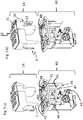
- Fig. 5 a) and b ) show in the upper part the device (1), in a) loaded with the liquid waste container (11) (not visible) and multiwell plate (20), and in b) loaded additionally with tip holder (30) comprising tip holder vessels (32) and tips (31).
- an exemplary separation and heating station (40) is shown.
- the magnetic separation and incubation station (40) comprises a holder for receiving sample vessels.
- Movable magnets (42) are connected to an actuator (43).
- the actuator (43) is configured to move the movable magnets (42) into proximity or away from the vessels (24).
- the magnetic separation and incubation station (40) further comprises a heat block (44).
- the heat block (44) is configured to contact the vessels (24) to transfer heat to the contents of the vessels (24).
- a container (45) is integrally formed with said magnetic separation and heating station (40).
- the container (45) comprises a closed bottom (46), side walls (47) and an open top (48).
- the container is configured to receive a pipette tip holder (32).
- the multipart device (1A) can be loaded on the separation and incubation station (40) either without the tips (31) in the tip holder (39), as shown in Fig. 5a ) and Fig. 6 , or with the tips (31) in the tip holder (30) pre-loaded, as in Fig. 5b ).
- pin (41) with which ridge (6) and notch (12) align are also shown.
- Figs. 6a) to 6d show different stages of loading of the multi-part device (1A) into the separation and incubation station (40).
- the multi-part device (1A) is loaded onto the separation station (40) without the tip holder (30).
- the tip holder (30) comprising tips (31) is loaded into the device (1) and container (45).
- the separation and incubation station (40) comprises a downholding mechanism (49) which is open in Figs. 6a) to 6c ).
- the downholding mechanism (49) is moved into a locked position, shown in Fig. 6d ), which downholds the multipart device (1A) in the separation and incubation station (40). This ensures that the multipart device (1A) stays in place during magnetic separation.
- the closing and opening is mediated by actuator (43).
- Fig. 7 shows the device 1 after discarding the multiwell plate (20) and tip holder (30).
- the liquid waste container (11) can be easily removed and the contents discarded.
- Fig. 8 shows a system (60) comprising a magnetic separation and incubation station (40) and a barcode reader (61).
- the system further comprises a computer controller (62). Further, the system comprises a multi-pipetting device (63).
Landscapes
- Chemical & Material Sciences (AREA)
- Health & Medical Sciences (AREA)
- Life Sciences & Earth Sciences (AREA)
- Engineering & Computer Science (AREA)
- Organic Chemistry (AREA)
- Genetics & Genomics (AREA)
- Wood Science & Technology (AREA)
- Zoology (AREA)
- Analytical Chemistry (AREA)
- Biomedical Technology (AREA)
- General Engineering & Computer Science (AREA)
- Biotechnology (AREA)
- Bioinformatics & Cheminformatics (AREA)
- General Health & Medical Sciences (AREA)
- Physics & Mathematics (AREA)
- Chemical Kinetics & Catalysis (AREA)
- Biochemistry (AREA)
- Clinical Laboratory Science (AREA)
- Molecular Biology (AREA)
- Microbiology (AREA)
- Biophysics (AREA)
- Immunology (AREA)
- Proteomics, Peptides & Aminoacids (AREA)
- Plant Pathology (AREA)
- Crystallography & Structural Chemistry (AREA)
- General Physics & Mathematics (AREA)
- Pathology (AREA)
- Automatic Analysis And Handling Materials Therefor (AREA)
- Measuring Or Testing Involving Enzymes Or Micro-Organisms (AREA)
- Sampling And Sample Adjustment (AREA)
- Apparatus Associated With Microorganisms And Enzymes (AREA)
Claims (11)
- Dispositif en plusieurs parties (1A) comprenant un dispositif (1), ledit dispositif (1) comprenant une partie support (2), ladite partie support (2) étant configurée pour recevoir un porte-embouts (30) et une plaque multipuits (20), dans lequel ladite plaque multipuits (20) comprend au moins une rangée (23 a, b, c) de récipients (24) et une rangée d'ouvertures (21), dans lequel lesdits récipients (24) comprennent un fond fermé et un haut ouvert, ledit dispositif en plusieurs parties (1A) comprenant en outre le porte-embouts (30) et la plaque multipuits (20), caractérisé en ce que ledit dispositif en plusieurs parties (1A) comprenant en outre un contenant de déchet liquide (11) et ladite partie support (2) étant configurée pour recevoir le contenant de déchet liquide (11), dans lequel lesdites ouvertures (21) se trouvent au-dessus du contenant de déchet liquide (11) lorsque ledit contenant de déchet liquide (11) et ladite plaque multipuits (20) sont montés sur ladite partie support (2), dans lequel ledit contenant de déchet liquide (11) a de longues parois latérales (13) opposées et de courtes parois latérales (16) opposées qui englobent un volume interne, et dans lequel le contenant de déchet liquide (11) comprend un fond fermé (15) et un haut ouvert (14).
- Dispositif en plusieurs parties (1A) selon la revendication 1, dans lequel ledit porte-embouts (30) comprend une rangée de récipients de porte-embouts (32) formés individuellement configurés pour recevoir des embouts de pipettes (31), et dans lequel lesdites rangées (23 a, b, c) de récipients (24), la rangée d'ouvertures (21) et ladite rangée de récipients de porte-embouts (32) comprennent un nombre égal de récipients (24)/ouvertures (21)/récipients de porte-embouts (32).
- Dispositif en plusieurs parties (1A) selon la revendication 2, dans lequel lesdites rangées (23 a, b, c) de récipients (24), ladite rangée d'ouvertures (21) et ladite rangée de récipients de porte-embouts (32) sont alignées de façon à ce qu'un transfert de liquide en utilisant un dispositif de multi-pipetage soit autorisé.
- Dispositif en plusieurs parties (1A) selon la revendication 1, dans lequel l'une desdites longues parois latérales (13) comprend une encoche (12).
- Dispositif en plusieurs parties (1A) selon le revendication 1 à 3, dans lequel ladite partie support (2) comprend une enceinte (3), ladite enceinte (3) étant configurée pour recevoir le contenant de déchet liquide (11).
- Dispositif en plusieurs parties (1A) selon la revendication 5, dans lequel ladite enceinte (3) comprend de courtes parois latérales (4a, 4b) opposées et deux longues parois latérales (5a, 5b) opposées.
- Dispositif en plusieurs parties (1A) selon la revendication 6, dans lequel l'une desdites longues parois latérales (5b) comprend une arête (6), ladite arête (6) étant configurée pour s'aligner avec l'encoche (12) de l'une des longues parois latérales (13) du contenant de déchet liquide (11).
- Dispositif en plusieurs parties (1A) selon l'une quelconque des revendications 5 à 7, dans lequel ladite enceinte (3) dudit dispositif (1) est formée d'une seule pièce, dans lequel ladite enceinte (3) comprend un fond fermé et un haut ouvert.
- Procédé d'élimination de déchet liquide pendant la séparation magnétique d'un analyte, comprenant- la fourniture d'un dispositif (1), d'un contenant de déchet liquide (11) et d'une plaque multipuits (20) comprenant des échantillons liquides montés sur ledit dispositif (1) à une station de séparation magnétique (40)- la fourniture de particules magnétiques audit échantillon- la liaison dudit analyte, s'il est présent dans ledit échantillon, auxdites particules magnétiques- la séparation desdites particules magnétiques et desdits échantillons liquides en utilisant une séparation magnétique- l'élimination dudit échantillon liquide par transfert dudit échantillon liquide vers ledit contenant de déchet liquide (11) en utilisant un système de transfert de liquide, ce qui permet d'éliminer le déchet liquide pendant la séparation magnétique, dans lequel ledit dispositif (1) est compris dans un dispositif en plusieurs parties (1A) selon les revendications 1 à 8, ledit dispositif en plusieurs parties (1A) comprenant ledit dispositif (1), ledit contenant de déchet liquide (11) et ladite plaque multipuits (20), et dans lequel ledit déchet liquide est éliminé par retrait du dispositif en plusieurs parties (1A) de la station de séparation magnétique (40).
- Procédé selon la revendication 9, dans lequel ledit analyte est un analyte d'acide nucléique.
- Procédé selon l'une quelconque des revendications 9 à 10, dans lequel ledit dispositif est réutilisable.
Priority Applications (6)
| Application Number | Priority Date | Filing Date | Title |
|---|---|---|---|
| EP16158300.0A EP3213819B1 (fr) | 2016-03-02 | 2016-03-02 | Dispositif et méthode de séparation |
| US15/442,316 US10577596B2 (en) | 2016-03-02 | 2017-02-24 | Device for separation |
| JP2017034502A JP6826911B2 (ja) | 2016-03-02 | 2017-02-27 | 分離装置 |
| CN201710117926.2A CN107153024B (zh) | 2016-03-02 | 2017-03-01 | 用于分离的装置 |
| CN202111036911.6A CN113916641A (zh) | 2016-03-02 | 2017-03-01 | 用于分离的装置 |
| JP2021004818A JP7032580B2 (ja) | 2016-03-02 | 2021-01-15 | 分離装置 |
Applications Claiming Priority (1)
| Application Number | Priority Date | Filing Date | Title |
|---|---|---|---|
| EP16158300.0A EP3213819B1 (fr) | 2016-03-02 | 2016-03-02 | Dispositif et méthode de séparation |
Publications (2)
| Publication Number | Publication Date |
|---|---|
| EP3213819A1 EP3213819A1 (fr) | 2017-09-06 |
| EP3213819B1 true EP3213819B1 (fr) | 2021-09-29 |
Family
ID=55456648
Family Applications (1)
| Application Number | Title | Priority Date | Filing Date |
|---|---|---|---|
| EP16158300.0A Active EP3213819B1 (fr) | 2016-03-02 | 2016-03-02 | Dispositif et méthode de séparation |
Country Status (4)
| Country | Link |
|---|---|
| US (1) | US10577596B2 (fr) |
| EP (1) | EP3213819B1 (fr) |
| JP (2) | JP6826911B2 (fr) |
| CN (2) | CN113916641A (fr) |
Families Citing this family (3)
| Publication number | Priority date | Publication date | Assignee | Title |
|---|---|---|---|---|
| KR102110647B1 (ko) * | 2018-05-03 | 2020-05-14 | 주식회사 파나진 | 대용량 샘플로부터 핵산을 추출하는 방법 및 이를 이용한 핵산추출시스템 |
| EP3566771B1 (fr) | 2018-05-09 | 2023-09-06 | F. Hoffmann-La Roche AG | Système de laboratoire et procédé pour séparer des impuretés contenues dans des échantillons d'essai |
| WO2020261124A1 (fr) * | 2019-06-27 | 2020-12-30 | 3M Innovative Properties Company | Articles, systèmes et procédés de transfert de liquide et d'inoculation automatisée |
Family Cites Families (24)
| Publication number | Priority date | Publication date | Assignee | Title |
|---|---|---|---|---|
| EP0884104B1 (fr) | 1997-06-09 | 2005-10-12 | F. Hoffmann-La Roche Ag | Dispositif jetable pour analyses |
| JPH11266864A (ja) * | 1998-03-19 | 1999-10-05 | Hitachi Ltd | 核酸の精製方法および精製用装置 |
| WO2002072423A1 (fr) * | 2001-03-09 | 2002-09-19 | Biomicro Systems, Inc. | Couvercle de microplaque |
| US20050042146A1 (en) * | 2003-08-19 | 2005-02-24 | Fuji Photo Film Co., Ltd. | Rack for extracting apparatuses |
| JP2006061031A (ja) * | 2004-08-25 | 2006-03-09 | Hitachi Maxell Ltd | 化学分析装置、分析処理チップ、および化学分析方法 |
| US20070092403A1 (en) * | 2005-10-21 | 2007-04-26 | Alan Wirbisky | Compact apparatus, compositions and methods for purifying nucleic acids |
| EP1839756A1 (fr) * | 2006-03-31 | 2007-10-03 | F.Hoffmann-La Roche Ag | Appareil de séparation de particules magnétiques de liquides contenant ces particules, et un ensemble de cuves destiné à être empoyé avec un tel appareil |
| CN101595573A (zh) | 2007-01-30 | 2009-12-02 | 电气化学工业株式会社 | Led光源单元 |
| WO2009078779A1 (fr) | 2007-12-14 | 2009-06-25 | Ge Healthcare Bio-Sciences Ab | Cassette pour tubes à essais |
| EP2189218A1 (fr) | 2008-11-12 | 2010-05-26 | F. Hoffmann-Roche AG | Séparation utilisant un couvercle de plaque multipuits |
| EP2373975B1 (fr) * | 2008-12-19 | 2020-04-01 | 3M Innovative Properties Company | Système et procédé de traitement d'échantillons |
| EP3663004B1 (fr) * | 2009-05-15 | 2022-01-26 | Gen-Probe Incorporated | Procédé et appareil pour la réalisation d'une procédure de séparation magnétique |
| CN102472695B (zh) | 2009-07-09 | 2014-07-16 | 凸版印刷株式会社 | 核酸提取用试剂盒、核酸提取方法和核酸提取装置 |
| WO2011103288A1 (fr) * | 2010-02-17 | 2011-08-25 | Precelleon, Inc. | Séparateur de cellules biologiques et kit jetable |
| JP5292267B2 (ja) * | 2009-12-16 | 2013-09-18 | 株式会社日立ハイテクノロジーズ | 試料処理装置、試料処理方法及びこれらに使用する反応容器 |
| WO2011136624A2 (fr) * | 2010-04-30 | 2011-11-03 | (주)바이오니아 | Dispositif de purification automatique d'échantillon biologique à unité d'application de champ magnétique, procédé pour extraire une substance cible d'un échantillon biologique, et procédé d'expression et de purification de protéine |
| KR20130029128A (ko) | 2010-07-23 | 2013-03-21 | 베크만 컬터, 인코포레이티드 | 실시간 pcr용 용기 |
| KR101420094B1 (ko) * | 2010-10-27 | 2014-07-17 | (주)바이오니아 | 다양한 생체시료분석을 위한 전자동실시간정량증폭장비, 다양한 생체시료분석을 위한 자동정제 및 반응준비 장치, 전자동 핵산정제 및 실시간 정량 유전자증폭 방법, 전자동 핵산정제방법, 실시간정량pcr을 이용한 병원균의 전자동 생균수검사방법, 정량면역pcr을 이용한 전자동 항원농도획득방법 및 타겟항원에 라벨링된 부착용 타겟핵산의 정제방법 |
| US20140315325A1 (en) * | 2011-11-16 | 2014-10-23 | Epistem Limited | Assembly comprising a reaction vessel and a sample matrix, sample matrix comprising an upper adsorbent layer and a lower lateral flow layer |
| KR101762295B1 (ko) * | 2012-02-10 | 2017-08-04 | (주)바이오니아 | 생체시료의 자동 분석 장치 및 방법 |
| KR101555534B1 (ko) * | 2012-11-30 | 2015-10-06 | (주)바이오니아 | 전자동 무세포 단백질 제조장비 및 제조방법 |
| CN103394410B (zh) * | 2013-07-25 | 2016-04-20 | 博奥生物集团有限公司 | 一种位置可调节的智能磁力架 |
| CN103789198B (zh) * | 2014-02-27 | 2015-09-16 | 苏州天隆生物科技有限公司 | 全自动核酸提取仪 |
| DE202014102945U1 (de) * | 2014-06-27 | 2014-07-14 | Analytik Jena Ag | Heiz- und Magnetmodul für eine Vorrichtung zur Aufreinigung von Nukleinsäuren |
-
2016
- 2016-03-02 EP EP16158300.0A patent/EP3213819B1/fr active Active
-
2017
- 2017-02-24 US US15/442,316 patent/US10577596B2/en active Active
- 2017-02-27 JP JP2017034502A patent/JP6826911B2/ja active Active
- 2017-03-01 CN CN202111036911.6A patent/CN113916641A/zh active Pending
- 2017-03-01 CN CN201710117926.2A patent/CN107153024B/zh active Active
-
2021
- 2021-01-15 JP JP2021004818A patent/JP7032580B2/ja active Active
Also Published As
| Publication number | Publication date |
|---|---|
| CN107153024A (zh) | 2017-09-12 |
| JP2017153474A (ja) | 2017-09-07 |
| JP6826911B2 (ja) | 2021-02-10 |
| CN107153024B (zh) | 2021-09-14 |
| CN113916641A (zh) | 2022-01-11 |
| US20170253870A1 (en) | 2017-09-07 |
| JP7032580B2 (ja) | 2022-03-08 |
| EP3213819A1 (fr) | 2017-09-06 |
| JP2021052807A (ja) | 2021-04-08 |
| US10577596B2 (en) | 2020-03-03 |
Similar Documents
| Publication | Publication Date | Title |
|---|---|---|
| US11466263B2 (en) | Diagnostic apparatus to extract nucleic acids including a magnetic assembly and a heater assembly | |
| JP7473597B2 (ja) | 自動化された診断アナライザおよびその動作のための方法 | |
| EP2192186B1 (fr) | Système et précédé pour l'extraction automatisée des acides nucléiques | |
| CN102841212B (zh) | 用于处理封闭的样品管的系统 | |
| US7985375B2 (en) | Sample preparation system and method for processing clinical specimens | |
| CN101978273B (zh) | 用于处理临床标本的样品制备系统 | |
| US9650626B2 (en) | Kit for nucleic acid extraction and a nucleic acid extractor | |
| JP2026004307A (ja) | 試料チューブ用ラック | |
| EP3165916B1 (fr) | Appareil de prétraitement | |
| JP7032580B2 (ja) | 分離装置 | |
| CN107257712B (zh) | 样本容器架、用于将样本容器锁定在样本容器架和样本容器架系统中的方法 | |
| JP2025134738A (ja) | 生物学的サンプルを処理するための自動分析システム | |
| CN214452774U (zh) | 吸管端固持器 | |
| US12599909B2 (en) | Tube tray for secondary tubes, secondary tube handling module, and method of handling secondary tubes in an automated processing system | |
| KR20180112844A (ko) | 패키징 및 자동화 시스템에서 스크류탑 용기에 접근하기 위한 장치 | |
| EP2703820A1 (fr) | Panier de déchets à pointe mobile | |
| US20220176380A1 (en) | A holder for pipette tips | |
| HK1180391A1 (zh) | 用於为样品管去盖和重新加盖的装置 |
Legal Events
| Date | Code | Title | Description |
|---|---|---|---|
| PUAI | Public reference made under article 153(3) epc to a published international application that has entered the european phase |
Free format text: ORIGINAL CODE: 0009012 |
|
| STAA | Information on the status of an ep patent application or granted ep patent |
Free format text: STATUS: THE APPLICATION HAS BEEN PUBLISHED |
|
| AK | Designated contracting states |
Kind code of ref document: A1 Designated state(s): AL AT BE BG CH CY CZ DE DK EE ES FI FR GB GR HR HU IE IS IT LI LT LU LV MC MK MT NL NO PL PT RO RS SE SI SK SM TR |
|
| AX | Request for extension of the european patent |
Extension state: BA ME |
|
| STAA | Information on the status of an ep patent application or granted ep patent |
Free format text: STATUS: REQUEST FOR EXAMINATION WAS MADE |
|
| 17P | Request for examination filed |
Effective date: 20180306 |
|
| RBV | Designated contracting states (corrected) |
Designated state(s): AL AT BE BG CH CY CZ DE DK EE ES FI FR GB GR HR HU IE IS IT LI LT LU LV MC MK MT NL NO PL PT RO RS SE SI SK SM TR |
|
| STAA | Information on the status of an ep patent application or granted ep patent |
Free format text: STATUS: EXAMINATION IS IN PROGRESS |
|
| 17Q | First examination report despatched |
Effective date: 20180604 |
|
| GRAP | Despatch of communication of intention to grant a patent |
Free format text: ORIGINAL CODE: EPIDOSNIGR1 |
|
| STAA | Information on the status of an ep patent application or granted ep patent |
Free format text: STATUS: GRANT OF PATENT IS INTENDED |
|
| RIC1 | Information provided on ipc code assigned before grant |
Ipc: B01L 9/00 20060101AFI20210115BHEP Ipc: C12N 15/10 20060101ALI20210115BHEP Ipc: G01N 35/02 20060101ALI20210115BHEP Ipc: G01N 35/00 20060101ALI20210115BHEP |
|
| INTG | Intention to grant announced |
Effective date: 20210210 |
|
| GRAJ | Information related to disapproval of communication of intention to grant by the applicant or resumption of examination proceedings by the epo deleted |
Free format text: ORIGINAL CODE: EPIDOSDIGR1 |
|
| STAA | Information on the status of an ep patent application or granted ep patent |
Free format text: STATUS: EXAMINATION IS IN PROGRESS |
|
| GRAP | Despatch of communication of intention to grant a patent |
Free format text: ORIGINAL CODE: EPIDOSNIGR1 |
|
| STAA | Information on the status of an ep patent application or granted ep patent |
Free format text: STATUS: GRANT OF PATENT IS INTENDED |
|
| INTC | Intention to grant announced (deleted) | ||
| INTG | Intention to grant announced |
Effective date: 20210429 |
|
| GRAS | Grant fee paid |
Free format text: ORIGINAL CODE: EPIDOSNIGR3 |
|
| GRAA | (expected) grant |
Free format text: ORIGINAL CODE: 0009210 |
|
| STAA | Information on the status of an ep patent application or granted ep patent |
Free format text: STATUS: THE PATENT HAS BEEN GRANTED |
|
| AK | Designated contracting states |
Kind code of ref document: B1 Designated state(s): AL AT BE BG CH CY CZ DE DK EE ES FI FR GB GR HR HU IE IS IT LI LT LU LV MC MK MT NL NO PL PT RO RS SE SI SK SM TR |
|
| REG | Reference to a national code |
Ref country code: GB Ref legal event code: FG4D |
|
| REG | Reference to a national code |
Ref country code: CH Ref legal event code: EP Ref country code: AT Ref legal event code: REF Ref document number: 1433734 Country of ref document: AT Kind code of ref document: T Effective date: 20211015 |
|
| REG | Reference to a national code |
Ref country code: DE Ref legal event code: R096 Ref document number: 602016064229 Country of ref document: DE |
|
| REG | Reference to a national code |
Ref country code: IE Ref legal event code: FG4D |
|
| REG | Reference to a national code |
Ref country code: LT Ref legal event code: MG9D |
|
| PG25 | Lapsed in a contracting state [announced via postgrant information from national office to epo] |
Ref country code: NO Free format text: LAPSE BECAUSE OF FAILURE TO SUBMIT A TRANSLATION OF THE DESCRIPTION OR TO PAY THE FEE WITHIN THE PRESCRIBED TIME-LIMIT Effective date: 20211229 Ref country code: FI Free format text: LAPSE BECAUSE OF FAILURE TO SUBMIT A TRANSLATION OF THE DESCRIPTION OR TO PAY THE FEE WITHIN THE PRESCRIBED TIME-LIMIT Effective date: 20210929 Ref country code: LT Free format text: LAPSE BECAUSE OF FAILURE TO SUBMIT A TRANSLATION OF THE DESCRIPTION OR TO PAY THE FEE WITHIN THE PRESCRIBED TIME-LIMIT Effective date: 20210929 Ref country code: BG Free format text: LAPSE BECAUSE OF FAILURE TO SUBMIT A TRANSLATION OF THE DESCRIPTION OR TO PAY THE FEE WITHIN THE PRESCRIBED TIME-LIMIT Effective date: 20211229 Ref country code: RS Free format text: LAPSE BECAUSE OF FAILURE TO SUBMIT A TRANSLATION OF THE DESCRIPTION OR TO PAY THE FEE WITHIN THE PRESCRIBED TIME-LIMIT Effective date: 20210929 Ref country code: SE Free format text: LAPSE BECAUSE OF FAILURE TO SUBMIT A TRANSLATION OF THE DESCRIPTION OR TO PAY THE FEE WITHIN THE PRESCRIBED TIME-LIMIT Effective date: 20210929 Ref country code: HR Free format text: LAPSE BECAUSE OF FAILURE TO SUBMIT A TRANSLATION OF THE DESCRIPTION OR TO PAY THE FEE WITHIN THE PRESCRIBED TIME-LIMIT Effective date: 20210929 |
|
| REG | Reference to a national code |
Ref country code: NL Ref legal event code: MP Effective date: 20210929 |
|
| REG | Reference to a national code |
Ref country code: AT Ref legal event code: MK05 Ref document number: 1433734 Country of ref document: AT Kind code of ref document: T Effective date: 20210929 |
|
| PG25 | Lapsed in a contracting state [announced via postgrant information from national office to epo] |
Ref country code: LV Free format text: LAPSE BECAUSE OF FAILURE TO SUBMIT A TRANSLATION OF THE DESCRIPTION OR TO PAY THE FEE WITHIN THE PRESCRIBED TIME-LIMIT Effective date: 20210929 Ref country code: GR Free format text: LAPSE BECAUSE OF FAILURE TO SUBMIT A TRANSLATION OF THE DESCRIPTION OR TO PAY THE FEE WITHIN THE PRESCRIBED TIME-LIMIT Effective date: 20211230 |
|
| PG25 | Lapsed in a contracting state [announced via postgrant information from national office to epo] |
Ref country code: AT Free format text: LAPSE BECAUSE OF FAILURE TO SUBMIT A TRANSLATION OF THE DESCRIPTION OR TO PAY THE FEE WITHIN THE PRESCRIBED TIME-LIMIT Effective date: 20210929 |
|
| PG25 | Lapsed in a contracting state [announced via postgrant information from national office to epo] |
Ref country code: IS Free format text: LAPSE BECAUSE OF FAILURE TO SUBMIT A TRANSLATION OF THE DESCRIPTION OR TO PAY THE FEE WITHIN THE PRESCRIBED TIME-LIMIT Effective date: 20220129 Ref country code: SK Free format text: LAPSE BECAUSE OF FAILURE TO SUBMIT A TRANSLATION OF THE DESCRIPTION OR TO PAY THE FEE WITHIN THE PRESCRIBED TIME-LIMIT Effective date: 20210929 Ref country code: RO Free format text: LAPSE BECAUSE OF FAILURE TO SUBMIT A TRANSLATION OF THE DESCRIPTION OR TO PAY THE FEE WITHIN THE PRESCRIBED TIME-LIMIT Effective date: 20210929 Ref country code: PT Free format text: LAPSE BECAUSE OF FAILURE TO SUBMIT A TRANSLATION OF THE DESCRIPTION OR TO PAY THE FEE WITHIN THE PRESCRIBED TIME-LIMIT Effective date: 20220131 Ref country code: PL Free format text: LAPSE BECAUSE OF FAILURE TO SUBMIT A TRANSLATION OF THE DESCRIPTION OR TO PAY THE FEE WITHIN THE PRESCRIBED TIME-LIMIT Effective date: 20210929 Ref country code: NL Free format text: LAPSE BECAUSE OF FAILURE TO SUBMIT A TRANSLATION OF THE DESCRIPTION OR TO PAY THE FEE WITHIN THE PRESCRIBED TIME-LIMIT Effective date: 20210929 Ref country code: ES Free format text: LAPSE BECAUSE OF FAILURE TO SUBMIT A TRANSLATION OF THE DESCRIPTION OR TO PAY THE FEE WITHIN THE PRESCRIBED TIME-LIMIT Effective date: 20210929 Ref country code: EE Free format text: LAPSE BECAUSE OF FAILURE TO SUBMIT A TRANSLATION OF THE DESCRIPTION OR TO PAY THE FEE WITHIN THE PRESCRIBED TIME-LIMIT Effective date: 20210929 Ref country code: CZ Free format text: LAPSE BECAUSE OF FAILURE TO SUBMIT A TRANSLATION OF THE DESCRIPTION OR TO PAY THE FEE WITHIN THE PRESCRIBED TIME-LIMIT Effective date: 20210929 Ref country code: AL Free format text: LAPSE BECAUSE OF FAILURE TO SUBMIT A TRANSLATION OF THE DESCRIPTION OR TO PAY THE FEE WITHIN THE PRESCRIBED TIME-LIMIT Effective date: 20210929 |
|
| REG | Reference to a national code |
Ref country code: DE Ref legal event code: R097 Ref document number: 602016064229 Country of ref document: DE |
|
| PG25 | Lapsed in a contracting state [announced via postgrant information from national office to epo] |
Ref country code: DK Free format text: LAPSE BECAUSE OF FAILURE TO SUBMIT A TRANSLATION OF THE DESCRIPTION OR TO PAY THE FEE WITHIN THE PRESCRIBED TIME-LIMIT Effective date: 20210929 |
|
| PLBE | No opposition filed within time limit |
Free format text: ORIGINAL CODE: 0009261 |
|
| STAA | Information on the status of an ep patent application or granted ep patent |
Free format text: STATUS: NO OPPOSITION FILED WITHIN TIME LIMIT |
|
| 26N | No opposition filed |
Effective date: 20220630 |
|
| PG25 | Lapsed in a contracting state [announced via postgrant information from national office to epo] |
Ref country code: MC Free format text: LAPSE BECAUSE OF FAILURE TO SUBMIT A TRANSLATION OF THE DESCRIPTION OR TO PAY THE FEE WITHIN THE PRESCRIBED TIME-LIMIT Effective date: 20210929 |
|
| PG25 | Lapsed in a contracting state [announced via postgrant information from national office to epo] |
Ref country code: SI Free format text: LAPSE BECAUSE OF FAILURE TO SUBMIT A TRANSLATION OF THE DESCRIPTION OR TO PAY THE FEE WITHIN THE PRESCRIBED TIME-LIMIT Effective date: 20210929 |
|
| REG | Reference to a national code |
Ref country code: BE Ref legal event code: MM Effective date: 20220331 |
|
| PG25 | Lapsed in a contracting state [announced via postgrant information from national office to epo] |
Ref country code: LU Free format text: LAPSE BECAUSE OF NON-PAYMENT OF DUE FEES Effective date: 20220302 Ref country code: IT Free format text: LAPSE BECAUSE OF FAILURE TO SUBMIT A TRANSLATION OF THE DESCRIPTION OR TO PAY THE FEE WITHIN THE PRESCRIBED TIME-LIMIT Effective date: 20210929 Ref country code: IE Free format text: LAPSE BECAUSE OF NON-PAYMENT OF DUE FEES Effective date: 20220302 |
|
| PG25 | Lapsed in a contracting state [announced via postgrant information from national office to epo] |
Ref country code: BE Free format text: LAPSE BECAUSE OF NON-PAYMENT OF DUE FEES Effective date: 20220331 |
|
| PG25 | Lapsed in a contracting state [announced via postgrant information from national office to epo] |
Ref country code: HU Free format text: LAPSE BECAUSE OF FAILURE TO SUBMIT A TRANSLATION OF THE DESCRIPTION OR TO PAY THE FEE WITHIN THE PRESCRIBED TIME-LIMIT; INVALID AB INITIO Effective date: 20160302 |
|
| PG25 | Lapsed in a contracting state [announced via postgrant information from national office to epo] |
Ref country code: SM Free format text: LAPSE BECAUSE OF FAILURE TO SUBMIT A TRANSLATION OF THE DESCRIPTION OR TO PAY THE FEE WITHIN THE PRESCRIBED TIME-LIMIT Effective date: 20210929 Ref country code: MK Free format text: LAPSE BECAUSE OF FAILURE TO SUBMIT A TRANSLATION OF THE DESCRIPTION OR TO PAY THE FEE WITHIN THE PRESCRIBED TIME-LIMIT Effective date: 20210929 Ref country code: CY Free format text: LAPSE BECAUSE OF FAILURE TO SUBMIT A TRANSLATION OF THE DESCRIPTION OR TO PAY THE FEE WITHIN THE PRESCRIBED TIME-LIMIT Effective date: 20210929 |
|
| PG25 | Lapsed in a contracting state [announced via postgrant information from national office to epo] |
Ref country code: TR Free format text: LAPSE BECAUSE OF FAILURE TO SUBMIT A TRANSLATION OF THE DESCRIPTION OR TO PAY THE FEE WITHIN THE PRESCRIBED TIME-LIMIT Effective date: 20210929 |
|
| PG25 | Lapsed in a contracting state [announced via postgrant information from national office to epo] |
Ref country code: MT Free format text: LAPSE BECAUSE OF FAILURE TO SUBMIT A TRANSLATION OF THE DESCRIPTION OR TO PAY THE FEE WITHIN THE PRESCRIBED TIME-LIMIT Effective date: 20210929 |
|
| PGFP | Annual fee paid to national office [announced via postgrant information from national office to epo] |
Ref country code: CH Payment date: 20250401 Year of fee payment: 10 |
|
| REG | Reference to a national code |
Ref country code: CH Ref legal event code: U11 Free format text: ST27 STATUS EVENT CODE: U-0-0-U10-U11 (AS PROVIDED BY THE NATIONAL OFFICE) Effective date: 20260401 |
|
| PGFP | Annual fee paid to national office [announced via postgrant information from national office to epo] |
Ref country code: GB Payment date: 20260220 Year of fee payment: 11 |
|
| PGFP | Annual fee paid to national office [announced via postgrant information from national office to epo] |
Ref country code: DE Payment date: 20260219 Year of fee payment: 11 |
|
| PGFP | Annual fee paid to national office [announced via postgrant information from national office to epo] |
Ref country code: FR Payment date: 20260219 Year of fee payment: 11 |