EP3213925A2 - Procédé de comparaison de deux papiers, dispositif comprenant des moyens destinés à exécuter le procédé et programme informatique comprenant une mis en uvre du procédé - Google Patents
Procédé de comparaison de deux papiers, dispositif comprenant des moyens destinés à exécuter le procédé et programme informatique comprenant une mis en uvre du procédé Download PDFInfo
- Publication number
- EP3213925A2 EP3213925A2 EP17157590.5A EP17157590A EP3213925A2 EP 3213925 A2 EP3213925 A2 EP 3213925A2 EP 17157590 A EP17157590 A EP 17157590A EP 3213925 A2 EP3213925 A2 EP 3213925A2
- Authority
- EP
- European Patent Office
- Prior art keywords
- brightener
- paper
- proof
- measurement
- printing
- Prior art date
- Legal status (The legal status is an assumption and is not a legal conclusion. Google has not performed a legal analysis and makes no representation as to the accuracy of the status listed.)
- Withdrawn
Links
Images







Classifications
-
- B—PERFORMING OPERATIONS; TRANSPORTING
- B41—PRINTING; LINING MACHINES; TYPEWRITERS; STAMPS
- B41M—PRINTING, DUPLICATING, MARKING, OR COPYING PROCESSES; COLOUR PRINTING
- B41M5/00—Duplicating or marking methods; Sheet materials for use therein
-
- B—PERFORMING OPERATIONS; TRANSPORTING
- B41—PRINTING; LINING MACHINES; TYPEWRITERS; STAMPS
- B41M—PRINTING, DUPLICATING, MARKING, OR COPYING PROCESSES; COLOUR PRINTING
- B41M5/00—Duplicating or marking methods; Sheet materials for use therein
- B41M5/0011—Pre-treatment or treatment during printing of the recording material, e.g. heating, irradiating
-
- H—ELECTRICITY
- H04—ELECTRIC COMMUNICATION TECHNIQUE
- H04N—PICTORIAL COMMUNICATION, e.g. TELEVISION
- H04N1/00—Scanning, transmission or reproduction of documents or the like, e.g. facsimile transmission; Details thereof
- H04N1/46—Colour picture communication systems
- H04N1/50—Picture reproducers
- H04N1/506—Reproducing the colour component signals picture-sequentially, e.g. with reproducing heads spaced apart from one another in the subscanning direction
- H04N1/508—Reproducing the colour component signals picture-sequentially, e.g. with reproducing heads spaced apart from one another in the subscanning direction using the same reproducing head for two or more colour components
-
- H—ELECTRICITY
- H04—ELECTRIC COMMUNICATION TECHNIQUE
- H04N—PICTORIAL COMMUNICATION, e.g. TELEVISION
- H04N1/00—Scanning, transmission or reproduction of documents or the like, e.g. facsimile transmission; Details thereof
- H04N1/46—Colour picture communication systems
- H04N1/56—Processing of colour picture signals
- H04N1/60—Colour correction or control
Definitions
- the innovation proposed here concerns first and foremost a method for visual and metrical matching of two papers and a system operating according to the method.
- the innovation also relates to a computer program comprising an implementation of the method and to a computer in whose memory such a computer program is loaded.
- the printing industry typically provides the market with medium-run printing by digital printing and high-end printing by means of offset printing or the like. It is dependent on a variety of factors, as the according to the usual terminology in the following referred to as a print run final expression finally appears visually and metrologically. These factors include in particular the type of printing technology (digital printing, offset printing, flexographic printing, etc.), the colors used in each case, the printing paper (substrate) used, pressure settings (eg speed, contact pressure, etc.), as well as ambient conditions, such as the room temperature and humidity.
- the layout is created digitally on a screen and should achieve the same visual impression as possible later in the production run.
- color management To ensure this, all production steps are subjected to a generally known color management process (color management). In general, this quite complex process should ensure that a layout on each medium (e.g., monitor on the one hand and print run on the other) is identical.
- proof printing which is often referred to in technical terminology - and so also in the following - as a proof. Accordingly, the printer used for proof printing is referred to as a proof printer and proof printer is often an inkjet printer (inkjet printer) is used.
- Proof printing has two functions: On the one hand, the proof print serves as orientation for the operator of the press (printer) to set it accordingly for the print run and to continuously check whether the specifications are fulfilled during the entire print. On the other hand - and this is the focus in the following - the printout on the proof printer serves as a visual and contract proof for the customer. The subsequent print run must comply with this simulation within certain limits, otherwise complaints about the print run can occur.
- the goal of any proofing process is therefore to simulate a print object to be produced in large numbers for acceptance by the customer and, as a guideline for the print run, as accurately as possible in advance.
- inkjet printing systems of various types are used, which print specially matched to the inkjet proofing papers.
- optical brighteners are usually used in an amount of 0.1% to 3%, based on the pulp (receiving substrate). As with direct dye, the optical brighteners attract the fiber. Only then and when they are fixed on the fiber, the brightener molecules are fully effective. The optical brightener is therefore particularly closely connected to the fiber, as for example in the DE 199 17 742 C2 is described.
- the level of emission in the blue region of the spectrum corresponds indirectly to the OBA concentration present in the substrate of the edition or proof paper.
- Typical brighteners used in the printing industry absorb radiation energy in the invisible UV region of the spectrum (for example in the range from 300 nm to 380 nm) and emit it (almost directly) again in the visible, blue region of the electromagnetic spectrum in the region of 450 nm can be compensated in circulation papers the lack of blue described above effectively and inexpensively.
- Just the amplification effect at about 450 nm leads to a - desired - increase in the degree of whiteness when it is measured with UV luminescence. This phenomenon is called fluorescence. It causes a recording medium having a receiving substrate with optical brightener additive to appear whiter to the viewer than it is in reality. Brighteners are thus significantly different from the direct dyes, which absorb and emit light only in the visible spectrum without significantly shifting the incident wavelength.
- the problem is, however, the fact that the strength of the emission in the blue region of the spectrum of the UV radiation of the respective illumination is dependent and determines the UV component in the radiation emitted by the respective light source thus the white point of the respective paper. Varying UV levels, for example due to different light sources / illumination in a visual examination and a metrological test, lead to different white points. This results in a brightener-dependent (brightener-related) shift of the white point of the papers.
- the shifts at the white point explained here also have a direct influence on the colors printed on the paper, so that there is a shift of the color loci dependent on the brightener (brightener-induced shift of the color loci). Only by an identical brightener excitation colors appear relative to each other always the same.
- An object of the present invention is based on the situation outlined above to provide a method and a system for carrying out the method, by means of which the problem described can be solved, in particular to provide a method and a system by means of which provided as a proof paper Paper can be adapted to be simulated to a support paper in a manner that results metrologically and visually a luminaire-independent agreement or at least substantially such a match.
- a method for aligning a proof paper in particular an unleached proof paper (without OBA) or a proof paper with a comparatively low base concentration of a brightener, provided on a simulated edition paper for the purpose of obtaining a metrological and / or visual lichtartunoen agreement of both papers in that in order to approximate the proof paper to the support paper when producing a proof print by means of a proof printer, for example by means of an inkjet printer (proof inkjet) acting as a proof printer, a brightener, in particular, a brightener in the form of a whitening OBA ink is printed with an areal coverage specified as a brightener target surface coverage.
- the advantage of the invention is that the colorimetric white point of the proof paper is deliberately displaced by printing the brightener with the predetermined brightener target surface coverage, so that the desired luminaire-independent metrological and / or visual correspondence of the proof paper with the respective edition paper is achieved becomes. About the area coverage of the printed brightener while a necessary to achieve this match whitener emission is produced.
- the overlay paper and, on the other hand, a brightener chart printed on the proof paper by means of the proofer are compared with each other, wherein the brightener test chart comprises a plurality of measurement fields with different areal coverage of the brightener.
- the comparison is made, for example, by visual inspection or by measuring the support paper on the one hand and the brightener test chart printed on the proof paper by means of the proof printer on the other hand spectrophotometrically.
- the measuring fields with their different surface coverage of the brightener allow detection of the effect of the brightener on the proof paper. Based on an equality or sufficient equality of the edition paper and a measurement field of the brightener test chart, the areal coverage of the brightener of the respective measurement field can be used as a brightener target area coverage.
- a spectrophotometric measurement of the measuring fields automatically provides evaluable data on the effect of the brightener on the proof paper.
- the spectrophotometric measurement of the edition paper automatically provides evaluable data for the edition paper. Both are included in the automatic determination of the brightener target area coverage.
- each measuring field of the brightener test chart is measured twice by spectrophotometry, namely once with UV influence and once without UV influence or with a different UV influence compared to the first measurement.
- spectrophotometric measurement on the one hand a measurement without a filter influencing the UV component of the radiation emitted by the respective light source or the like and on the other hand a measurement with a filter influencing the UV component of the radiation emanating from the respective light source or The like, for example, a so-called UV-cut filter, perform, for example, a first measurement without UV-cut filter and a second measurement with UV-cut filter.
- a characteristic value for each areal coverage of the brightener is determined for each measurement field. This value encodes the brightener-induced emission of the respective measurement field and this results from the area coverage of the brightener used when printing the measurement field. Depending on the number of (evaluated) measuring fields results in a number of brightener-induced emissions.
- a look-up function or a look-up table is determined. This forms the basis for an automatic determination of the brightener target area coverage, ie the area coverage with which the proof paper is printed with brightener when creating a proof print by means of the proof printer.
- the edition paper in the spectrophotometric measurement of the edition paper, is measured twice, once with a first UV influence and once with a second UV influence different from the first UV influence, in particular once with UV influence and once without UV influence. Based on the measurement results of both measurements, a brightener-induced emission of the edition paper resulting from the brightener contained in the edition paper is determined. As part of the approximation of the proof paper to the circulation document, the issuance of the proof paper must be adjusted to the determined issuance of the circulation document. The determined emission of the circulation document is therefore the remission target value, ie the target remission. Based on the brightener-induced target emission, the brightener target area coverage is determined using the look-up function or the look-up table, with which the proof paper is printed with the brightener by means of the proof printer during proof printing.
- ink target surface coverage is determined on the basis of the measurement results without UV influence resulting measurement results of the spectrophotometric measurement of the edition paper and based on a spectrophotometric measurement of a printed by means of the proof printer on the proof paper color test chart. This is used when printing the Proof printing by the proof printer when printing inks is taken into account.
- the particular advantage of this embodiment is that interactions between brighteners, in particular a brightener in the form of a whitening OBA ink, and the conventional, coloring ink can also be detected here.
- a system for carrying out the method as described here and below comprises at least the proof printer, for example an inkjet printer functioning as a proof printer, and means for carrying out the method and / or individual embodiments of the method, for example a processing unit in the form of a computer, in the memory of which a computer program with an implementation of the method is loaded into software so that, when the computer program is executed and under the control of the computer program, the method is executable and executed during operation of the system and the processing unit.
- the proof printer for example an inkjet printer functioning as a proof printer
- means for carrying out the method and / or individual embodiments of the method for example a processing unit in the form of a computer, in the memory of which a computer program with an implementation of the method is loaded into software so that, when the computer program is executed and under the control of the computer program, the method is executable and executed during operation of the system and the processing unit.
- the latter comprises a proof printer for printing the proof paper and for printing the proof print, in particular an inkjet printer functioning as a proof printer, and a processing unit, for example a computer acting as a processing unit or a computer system functioning as a processing unit for carrying out the present invention and the method described below.
- the system is designed and set up to match a proof paper to a support paper to be simulated for the purpose of obtaining a metrological and / or visual match of the proof paper with the support paper, regardless of the type of light.
- a brightener with a brightener target surface coverage is provided for aligning the proof paper to the edition paper when producing a proof print on the proof paper Area coverage can be imprinted and is printed on the proof paper during operation of the system.
- a brightener test chart can be imprinted on the proof paper by means of the proof printer and, during operation of the system, such a brightener test chart is printed onto the proof paper by means of the proof printer using the brightener.
- the brightener test chart comprises a plurality of measuring fields and is printed by means of the proof printer so that the measuring fields have different surface coverage of the brightener.
- the support paper on the one hand and the brightener test chart on the proof paper on the other hand be measured spectrophotometrically and measured spectrophotometrically during operation of the system.
- the system itself may have corresponding, basically known measuring devices for the spectrophotometric measurement of the support paper and the brightener test chart.
- a measuring device or measuring devices belong only temporarily to the system, for example in the form of a portable measuring device or portable measuring devices, whose or their measurement results via a data link in a memory of the system, in particular a memory of the processing unit , be transmitted.
- each patch of the brightener test chart is measurable twice and is measured twice during operation of the system, especially in its configuration once with UV influence and once without UV influence, based on the measurement results of both measurements for each measurement field results in a brightener-induced result due to the respective areal coverage of the brightener Emission can be determined and is determined during operation of the system and wherein based on a detectable for all evaluated measuring fields brightener-induced emission, a look-up function or a look-up table can be determined and is determined during operation of the system.
- a due brightener-induced emission resulting from the overlay paper can be determined as a target remission and is determined during operation of the system, and the brightener target area coverage can be determined by means of the target reflectance using the look-up function or the look-up table during operation of the system.
- an ink target surface coverage can be determined on the basis of the measurement results without UV influence resulting measurement results of the spectrophotometric measurement of the edition paper and based on a spectrophotometric measurement of a printable by means of the proof printer on the proof paper color test chart and is determined during operation of the system, wherein, when printing proof proof by means of the proof printer, the ink target area coverage can be taken into account when printing inks and is taken into account in the operation of the system.
- the method described here and hereinafter for aligning a proof paper with a support paper is preferably implemented in software or in software and firmware and that Method is preferably implemented for automatic execution in the form of a computer program.
- the computer program is for execution by a processing unit (as in Fig. 7 shown). If procedural steps or procedural steps are described below, this refers to actions that take place on the basis of the computer program or under the control of the computer program, unless expressly stated that individual actions are initiated by an operator or a user of the computer program. At a minimum, any use of the term "automatic" means that the action in question is due to the computer program or under the control of the computer program.
- the present invention is also a computer program comprising program code means for performing all the steps of the subject method when the computer program is executed as part of an operation of a system for aligning a proof paper with a support paper.
- the invention is a computer program with program code means, in particular program code instructions, which are stored on a computer-readable medium to carry out all the steps of the subject method, when the computer program is loaded into a memory of a processing unit of a system for aligning a proof paper to a support paper and in Operating system.
- the implementation of the method described here and below can also take the form of firmware.
- firmware an implementation in firmware or in firmware and software or in firmware and Hardware is possible. Therefore, for the description presented here, the term software or the term computer program also includes other implementation options, namely, in particular, an implementation in firmware or in firmware and software or in firmware and hardware.
- a particular aspect of the invention in an inkjet printer functioning as a proof printer is an ink for use in the method presented here and below.
- This is intended for printing by means of the proof printer and has at least one brightener with a concentration of, for example, 0.2% to 40% and a carrier in a concentration of, for example, 0.2% -40%.
- the carrier causes on the one hand an increase in the brightener emission and on the other hand, an unwanted so-called "greening" effect is avoided.
- most water-soluble and colorless polymer and cellulose derivatives are suitable as carriers.
- an ink formulation useful for inkjet printing must have a number of properties to provide a long term stable printout. These properties depend primarily on the viscosity, solubility of additives contained therein, the compatibility of the combined additives, and the ability of the ink to "knock off” (retract into the receiving substrate for drying) into a recording medium. In addition, ink formulations should have good adhesion to a receiving substrate. For a long-term stable printing process, it is also essential that the ink does not block the inkjet printing nozzles in the long term.
- Typical inkjet inks for proofing and a used inkjet printer consist mainly of water, a water-miscible organic liquid, a dye containing at least 0.5 percent by weight, optionally a wetting agent, optionally a biocide, optionally a pH regulator and Silica particles with a content of 0.1 to 5 weight percent and are for example from the US 5,221,332 known.
- the US 5,925,178 describes pigmented inkjet inks.
- the ink to be used is preferably based on an aqueous solution containing at least one type of optical brightener at a concentration of 0.2% to 40%.
- the ink may be based on other solvents (e.g., alcohol).
- the ink must be printable by inkjet.
- optical brighteners are preferably 1,3,5-triazinyl derivatives of 4,4'-diaminostilbenes used, which differ primarily by additional sulfonic acid groups.
- Other possible optical brighteners include u.a. 4,4'-distyrylbiphenyl. This type of brightener has, according to current knowledge, a higher lightfastness. In general, however, any optical brightener can be used, which correspond in their excitation and emission spectrum as possible the optical brighteners used in the market for paper.
- a requirement specifically for proofing substrates and proof prints is, inter alia, a high lightfastness.
- This is understood to mean the optical stability of substrates and colors printed on them in relation to UV radiation.
- a so-called photoisomerization takes place under UV influence.
- the trans-cis ratio initially changes very quickly (minutes to hours) and then increasingly flattens out.
- the rate of transformation can be described in simplified terms as an exponential function, which increasingly approaches a metastable trans-cis ratio with increasing irradiation time.
- the proportion of active trans isomers in the brightener by irradiation prior to printing or in connection to obtain a predetermined or predetermined desired ratio of active trans isomers and inactive cis isomers in the brightener is reduced with the printing and / or a synthesis (original generation of the cis and trans isomers in the respectively desired ratio) of the brightener with a ratio corresponding to the desired ratio, or at least substantially corresponding ratio of active trans isomers and inactive cis isomers he follows.
- trans-cis ratio a desired ratio of active trans isomers and inactive cis isomers effected, for example, by irradiation for a predetermined or predeterminable duration
- the irradiation period is based, for example, on empirical values. Currently it is assumed that an irradiation period of five to six hours makes sense. The otherwise occurring only after the printing of the brightener aging in the form of the decrease of the active trans isomers is now given at the time of printing. Consequently, the brightener no longer or only to a considerably reduced extent by (further) decrease of the trans isomers after printing.
- the loss of emission intensity from the outset in connection with the targeted aging of the brightener can be compensated in the presented process by printing a higher brightener surface coverage.
- the respectively necessary brightener surface coverage results in the context of the determination of the brightener target surface coverage described here and below. Effectively, a photoisomerization-induced aging is thus reduced or the light fastness of a proof print is increased.
- FIG. 1 schematically shows a simplified printing process sequence with use of an inkjet printer 10.
- a print file 12 by means of a processing unit 14, for example, a processing unit 14 in the form of a computer system, processed and driving data 16 are generated for the inkjet printer 10. These are fed to the inkjet printer 10.
- the inkjet printer 10 processes a respective recording medium 18 for printing and inks 20, in particular standard inks 20. According to the drive data 16, the printer 10 generates the print 22 with the inks 20 on the recording medium 18, typically paper.
- inkjet printing is a well-described printing technology in which the actual printing motif is generated without contact between the printer 10 and a respective recording medium 18 and a recording substrate of the recording medium 18.
- a jet of single color drops is ejected in a defined direction toward the recording medium 18 by means of a print head. This results from the ejected, tiny color droplets in a basically known manner (see, eg US 4,021,818 and US 4,313,124 ) individual pressure points, which in turn depict the actual motif to be printed.
- the print 22 is created by a variable area overprinting of the basic colors of the printing industry. These are the colors cyan, magenta, yellow and black. Occasionally, special colors such as light cyan, light magenta etc. are used.
- the motif is set composed of halftone dots of different area coverage. The perception of the motive by humans is based on the subtractive and additive color mixing and arises thereby by the limited resolving power of the human eye.
- a so-called proofing is to simulate a respectively desired final print result as early as possible within the (printing) production process.
- a so-called proof print known as a proof, is created, which can be presented to the customer for control before the actual print run and on the basis of which the print run, ie the later actual print, is evaluated.
- the proof is often printed in the inkjet process by means of an inkjet printer 10, which then functions as a proof printer, and not with the printing process of the print run (for example offset printing) to be simulated.
- the support paper (receiving substrate) provided for the print run can not be used for proofing.
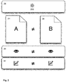
- FIG. 2 Fig. 12 shows the evaluation of a print on a pad paper 24 (left) and proof proof paper 26 (right) provided for a print run.
- a defined lighting 28 for Example with the average daylight (type of light D50) resulting in the edition paper 24 and the proof paper 26 each different, symbolically designated by "A" and "B” remissions (re-transmission of the unabsorbed portion of the incident light).
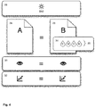
- FIG. 3 shows - with the same symbolism as FIG. 2 the desired goal, namely a visual impression 30 that is the same for different recording substrates 24, 26 (edition paper 24 on the one hand and proof paper 26) when viewed by a human observer / examiner, and identical or at least essentially the same results in a spectrophotometric measurement 32.
- the ink layer is printed by means of the inkjet printer 10 with conventional primary inkjet inks (cyan, magenta, yellow and black) 20, with optionally optional light gradations of the primary colors being used to improve the print quality.
- primary inkjet inks cyan, magenta, yellow and black
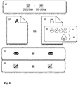
- FIG. 4 and FIG. 5 illustrate this graphically and the representation in FIG. 5 shows such an (ideal) method when creating a Proofmaschine 36 schematically simplified and with the same symbolism as in Figure 1.
- the processing unit 14 now processes not only the print file 12 but also additionally an electronically processable coding of specific print conditions 38 as well as an electronically processable coding of the white point 40 of the print paper 24 (FIG. FIG. 4 ). Furthermore, the processing unit 14 also processes for the respective inkjet printer 10 and the proof paper 26 used specific calibration data 42. From their processing by means of the processing unit 14 results in the control data 16 for the inkjet printer 10. This uses the respective proof paper 26 and standard inkjet inks 20 and optionally inkjet inks 44 with light gradations of the primary colors.
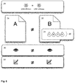
- the target situation shown results in an actual situation as shown in FIG. 6 , although in the spectrophotometric measurement 32 in the normal printing process control - usually for example under a so-called measurement condition M2 (illumination with the average daylight D50 according to ISO 3664: 2009 plus UV-cut filter) - a sufficient match can be achieved.
- M2 illumination with the average daylight D50 according to ISO 3664: 2009 plus UV-cut filter
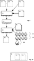
- FIG. 7 represents now - schematically simplified as FIG. 1 and FIG. 5 - the method proposed here to avoid the deviations outlined above. This is an extension from that in FIG. 5 and the related explanation, and both are expressly incorporated by reference to avoid repetition.
- the proof printer 10 is preferably an inkjet printer 10 and the further description is continued by way of example with reference to an inkjet printer 10 acting as a proof printer 10.
- electronically processable substrate alignment data 46 are processed by means of the processing unit 14. Together with those already (method according to Fig. 5 ) data of the print file 12, the printing conditions 38 and the calibration data 42, the processing unit 14 generates therefrom drive data 16 for the Proof Printer / Inkjet Printer 10.
- the proof printer 10 Due to the control data 16, the proof printer 10 now uses not only the standard inkjet inks 20 and optional inkjet inks 44 with light gradations of the primary colors, but also a whitener 48 which can be applied to the proofing paper 26 by means of the inkjet printer 10 functioning as a proof printer 10 Brightener in the form of a whitening OBA ink. Due to the additional use of the brightener 48 and by printing the proof paper 26 also with the brightener 48, the brightener-induced emission of the thus printed proof paper 26 is adapted to the emission of the support paper 24.
- the adjustment takes place in the form of an adaptation of the area coverage of the applied by the inkjet printer 10 on the proof paper 26 brightener 48 and due to the Substratanreteungswill 46 results in the printing of the proof paper 26 necessary area coverage of the applied by the inkjet printer 10 brightener 48th
- the printing of the brightener 48 on the proof paper 26 is preferably carried out together with the printing of the ink 20; 20, 44.
- proof and print run are independent of the type of illumination 28, both initially and remotely for the papers 26, 24 used, both metrologically and visually.
- the condition is that there are constant conditions during each comparison, ie the same light source 28 both Samples (overlay paper 24 and proof paper 26) are illuminated and the same instrument used to measure both samples. Since the remission behavior of both papers 24, 26 is matched to one another by means of the brightener 48 applied to the proof paper 26, they behave the same even with different illumination in the case of the visual matching 30 and the measurement 32. If a deviation from the print run now occurs when the proof is printed correctly, an error in the printing process itself can be assumed. In contrast, color deviations due to optical brighteners can be excluded.
- Papers and printed matter are typically measured spectrally. Coordinates in the CIE Lab color space (CIE Lab data) are calculated from the spectral data.
- CIE Lab data Coordinates in the CIE Lab color space
- the procedure for spectral measurement and for the conversion of the measurement results into CIE-Lab data is basically known per se and, for example, in the textbook “ Handbuch der Printmedien “, Springer Berlin Heidelberg, ISBN 978-3-540-66941-8 , described.
- a combined measurement on the one hand under a first measurement condition for example, a measurement without UV-cut filter, in particular a measurement under the measurement condition M1
- a second measurement condition for example a Measurement with UV-cut filter, in particular a measurement under the measurement condition M2
- a combined measurement with two basically arbitrary, different types of light in consideration for example, with daylight or a daylight equivalent (type of light D50) on the one hand and a light bulb or a light source with the emission spectrum of a light bulb on the other.
- the difference between two such measurements is a measure of the effect / emission of the optical brightener.
- a measurement with whitener-induced emission (e.g., without UV-cut filter and, for example, D50 standard illuminant) is always compared with a measurement without whitener-induced emission (e.g., UV-cut filter or, for example, incandescent-type incandescent light bulb).
- the measurements are ideally carried out with a spectrophotometer and, in principle, a commercially available spectrophotometer is suitable for such a measurement.
- any device capable of capturing spectral data for the visible range is suitable.
- the determination of the brightener-induced emission can, for example, be applied to spectral values or colorimetric values.
- spectral values for example, a determination of a difference of the area integrals under a respective spectral value curve comes into consideration.
- a consideration of a difference of a remission comes a single wavelength in the emission range of the brightener and a remission of another, not influenced by the brightener wavelength (peak difference, eg 440nm to 780nm) into consideration.
- a comparison of the blue effect may be considered, in particular by forming a ⁇ b * value of the CIE Lab coordinates between the two measurements, or alternatively comparable colorimetric values are possible, e.g. LCH, XYZ, HSB.
- an electronically processable coding of the brightener-induced emission is required.
- look-up data is proposed as such electronically processable coding.
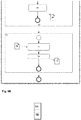
- FIG. 9 shows a method for determining such data schematically simplified in the form of a flowchart (BPMN model, Business Process Model and Notation).
- BPMN model Business Process Model
- the remission characteristic of a combination of proof paper 26 and applied by means of the inkjet printer 10 whitener 48 is determined at different surface coverage.
- a correlation results between a respective area coverage of the brightener 48 and the expected brightener-induced emission.
- the values determined are the look-up data or the basis for look-up data.
- a test chart 52 with a predetermined or predefinable number of measuring fields 54 ( Fig. 10 ) generated.
- Each measuring field 54 is printed by means of the inkjet printer 10 by printing a brightener 48 on the proofing paper 26, in particular by printing an OBA ink as a brightener 48.
- the test chart 52 is hereinafter referred to as Aufhellertestchart 52.
- the measuring fields 54 differ from one another by a different area coverage of the brightener 48.
- the representation in FIG. 10 shows - by way of example only - individual conceivable brightener test charts 52 with measuring fields 54 included therein.
- the graduation of the area coverage shown there (0%, 50%, 100%, 0%, 25%, 50%, 75%, 100% and 0%, 20%, 40%, 60%, 80%, 100%) is to be understood merely as an example and likewise other gradations, also non-linear gradations and gradations, which begin with an area coverage greater than 0% and / or smaller with an area coverage as 100% end, conceivable.
- the area coverage is increased by a predetermined or predefinable step size, starting from a minimum area coverage, for example 0%, until reaching a maximum area coverage, for example 100%.
- first spectral values 62 result, and second results due to the second measurement 60 Spectral values 64.
- ⁇ M 1 ( ⁇ ) at the first measurement 58 (first measurement condition, in particular measurement condition M1) at the wavelength ⁇ determined spectral value and corresponding ⁇ M 2 ( ⁇ ) in the second measurement 60 (second measurement condition, in particular measurement condition M2) at the wavelength ⁇ is determined spectral value.
- the result thus determined for the respective area coverage is stored 68.
- the measurement field evaluation 56 is repeated in accordance with the number of measurement fields 54 encompassed by the brightener test chart 52 until all measurement fields 54 have been evaluated and the value resulting for each measurement field 54 and its area coverage - the respective brightener-induced is stored 68 - 66 AE emission s.
- a look-up function creation 70 creates the look-up function.
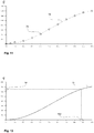
- the stored 68 brightener-induced emissions are plotted 66 ⁇ E s above the area coverage (step 72), and a set of points results, as shown by way of example in the illustration in FIG FIG. 11 is shown.
- the area coverage of the brightener 48 is plotted in percent and on the ordinate the brightener-induced emission.
- Each point 74 results due to a respective brightener-induced emission 66 ⁇ E s above the respective area coverage for which this was determined.
- a polynomial 78 is laid by means of a polynomial formation 76.
- the polynomial 78 ( Fig. 9B ; Fig. 13 ), ie a mathematical description of the dependence of the brightener-induced emission 66 ⁇ E s on the surface coverage of the brightener 48, is the sought-after look-up function 78.
- a table can also be used as a look-up function 78 in which the brightener-induced emissions 66 .DELTA.E s are combined in pairs with the respectively underlying areal coverage of the brightener 48, wherein intermediate values are determined in a generally known manner by means of interpolation.
- a once-determined look-up function 78 may be used for a fixed combination of proof paper 26 and ink 20; 20, 44 are used again and again.
- inkjet inks 20; 20, 44 it may be useful to have a respective individual absorption of inkjet inks 20; 20, 44, since these can differ not only color-dependent (eg cyan vs. magenta), but with the same coloring effect in the visible range of the spectrum (magenta vs. magenta) between two different printing methods (and thus colorants).
- these are on the support paper 24 and the proof paper 26 prints with additional colors in addition to the above-mentioned primary colors necessary. Measurements in Reference to such additional prints are analogous to the procedure described above. However, these measurements are made on already brightened and aligned areas on the proof paper 26.
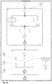
- FIG. 12 An approximation of the proof paper 26 to the edition paper 24 is carried out according to the in FIG. 12 schematically simplified in the form of a flowchart (BPMN model) Business Process Model and Notation method shown.
- BPMN model Business Process Model and Notation method
- the support paper 24 For correct simulation of a support paper 24 by a respective proof paper 26 together with a brightener 48 printed thereon, the support paper 24 must be measured spectrophotometrically and its remission - referred to below as a target remission 80 - to be determined.
- the support paper 24 is spectrophotometrically measured (first measurement 84, second measurement 86) under the effect of different measurement conditions, for example the first measurement condition M1 and the second measurement condition M2, and the total visible remission is recorded in each case.
- the measurement conditions may correspond to the measurement conditions in the evaluation of the measurement fields 54 of the brightener test chart 52. However, this is not a necessity and it is only important that two different measuring conditions are used within the framework of the target emission determination 82, of which at least one brightener contained in the edition paper 24 does not stimulate, or only slightly stimulates.
- the first measurement 84 takes place under UV influence.
- the second measurement 86 takes place without UV influence, for example by using a UV cut filter in the second measurement 86, whereas such a UV cut filter is not used in the first measurement 84 comes.
- the brightener contained in the support paper 24 then has no effect on the measured remission.
- first spectral values 88 result
- second spectral values 90 result, which are processed in a subsequent step 92.
- the emission of the brightener contained in the support paper 24 is determined, for example in the form of a difference of the spectral values 88, 90 according to equation (1), and a brightener-induced emission ⁇ E s of the support paper 24 is determined.
- the result is the brightener emission of the circulation paper 24, that is the desired target remission 80.
- the area coverage of the inks 20 -if possibly the inks 20, 44-necessary for the proofing paper 26 and the areal coverage of the brightener 48 necessary for the proofing paper 26 are determined 96, 98.
- the determination 98 of the area coverage of the brightener 48 necessary for the proof paper 26 is initially determined as part of substrate matching 94, is arbitrary, preferably the ink target area coverage (area coverage combination) ) 100 and then the brightener target area coverage (brightener area coverage) 102 is determined.
- the following is - without renouncing a broader generality - based on the in the presentation in FIG. 12
- the determination 96 of the area coverage of the inks 20 which is necessary for the proofing paper 26 is explained first by way of example.
- the second spectral values determined as a result of the second measurement 86 of the target emission determination 82 become 90 (second measurement condition, in particular measurement condition M2) used.
- second measurement condition in particular measurement condition M2
- the illumination takes place in the entire range of the visible spectrum. Due to the UV-cut filter, the brightener in the support paper 24 is not excited, so there is no brightener-induced emission.
- the proof paper 26 is printed with a color test chart.
- This is a test chart similar to the brightener test chart 52.
- the principle is the same as in the brightener test chart 52, so that reference is made to the explanations there.
- the measurement fields of the color test chart are measured - as described above in the brightener test chart 52 - but only under the second measurement condition, in particular the measurement condition M2 (with UV cut filter).
- the respectively resulting spectral values and the second spectral values 90 determined in the course of the target emission determination 82 are used to determine a non-brightener-induced remission characteristic according to equation (1).
- the associated necessary area coverage of the brightener 48-brightener target area coverage 102-can be read off via the look-up function 78, as shown in FIG FIG. 13 is shown.
- the target remission 80 results in a necessary areal coverage of the brightener 48 of 88%.
- the brightener target surface coverage 102 determined using the look-up function 78 or corresponding data is likewise a result of the substrate alignment 94.
- the determination 98 of the area coverage of the brightener 48 necessary for the proof paper 26 is completed and included the in FIG. 12 shown substrate alignment 94 is thus complete after the previous determination of the ink Zielflambackung 100 substrate alignment 94.
- the proof paper 26 is printed by means of the proof printer 10 (FIG. Fig. 7 ) the printing of the brightener 48 with the necessary for matching the proof paper 26 to the support paper 24 area coverage, namely with the determined brightener Zielflumbleigeckung 102.
- the substrate equalization data 46 so at least the determined brightener Zielflambaigeckung 102, by means of Processing unit 14 are processed and included in the processing in the determination of the drive data 16 for driving the Prooftikers 10.
- the proof printer 10 at least also prints the brightener 48, in particular the OBA ink, on the proof paper 26 and results in a proof print 36 (FIG. Fig. 7 ).
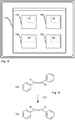
- the substrate alignment data 46 may be or may be associated with, for example, a graphical work environment 104, such as a desktop or the like, displayed on a computer monitor, or individual fields 106 of a work environment 104, as schematically simplified in the illustration of FIG FIG. 15 is shown.
- a work environment 104 for example, placing an object representing a print file 12 on the work environment 104 or a field 106 of the work environment 104 results in the print file 12 being associated with the work environment 104 or the respective field 106 of the work environment 104
- Substrate matching data 46 is printed.
- the graphical representation of individual substrate alignment data 46 in the background of each field 106 of FIG. 15 By way of example, illustrated work environment 104 is intended to indicate that exactly one set of substrate match data 46 is associated with each field 106 of the work environment 104.
- the substrate alignment data 46 is not or at least not necessarily part of the appearance appearing on the computer monitor.
- the Figures 16 and 17 show a possible result of the method based on an example made alignment of a proof paper 26 to a support paper 24. Both figures show the spectral reflectance 108 of the edition paper 24 and the spectral reflectance 110 of the proof paper 26 in comparison.
- FIG. 16 are initially only the conventional inks 20; 20, 44 have been applied in the determined target area coverage 100.
- the spectral reflectance curve of the adjusted proof paper 26 shows a change in the long wavelength visible region 114 which is close to the spectral reflectance of the support paper 24 (edition paper remission 108) in this part of the visible spectrum.
- the determined target area coverage 102 for the brightener 48 in particular the OBA ink, is added.
- the brightener 48 is preferably artificially irradiated prior to printing, alternatively a synthesis with corresponding proportions is conceivable.
- FIG. 18 shows an exemplary brightener molecule in the active (emissive) trans-form 120 that changes to the inactive (non-emissive) cis-shape 124 by the irradiation 122.
- a stable ratio of the two isomers is given for a given illumination, in particular illumination with the light D50, with which long-term stable results can be achieved.
- variable-area application of optical Auhellern 48 for the purpose of approximation of two papers 24, 26 to each other has been described in the present document in the embodiment, ie without waiving a wider generality, based on an inkjet process.
- inkjet process a number of other printing technologies are generally known (eg flexographic printing, gravure printing, offset printing, etc.), which are also based on variable-area printing.
- a brightener 48 together with the respective printing inks or at least one printing ink or in successive steps a brightener 48 and the printing inks are applied variable area coverage.
- the brightener 48 is contained in the form of a process-specific, in particular colorless printing ink formulation.
- a process-specific, in particular colorless printing ink formulation relates to a papermaking line with an additional flexographic printing unit at the end of the line in which a brightener is subsequently applied to give a paper a desired brightener emission, in particular by applying an ink formulation of the type mentioned above.
- the paper pulp to be contacted becomes in this example So no optical brightener 48 added for the purpose of white point increase, but the brightener 48 is subsequently applied by imprinting.
- the system is intended and arranged to execute the method and has means, for example a processing unit 14, for executing the method.
Landscapes
- Engineering & Computer Science (AREA)
- Multimedia (AREA)
- Signal Processing (AREA)
- Record Information Processing For Printing (AREA)
- Accessory Devices And Overall Control Thereof (AREA)
Applications Claiming Priority (2)
| Application Number | Priority Date | Filing Date | Title |
|---|---|---|---|
| DE102016202903 | 2016-02-24 | ||
| DE102016202898 | 2016-02-24 |
Publications (2)
| Publication Number | Publication Date |
|---|---|
| EP3213925A2 true EP3213925A2 (fr) | 2017-09-06 |
| EP3213925A3 EP3213925A3 (fr) | 2017-09-27 |
Family
ID=58266356
Family Applications (1)
| Application Number | Title | Priority Date | Filing Date |
|---|---|---|---|
| EP17157590.5A Withdrawn EP3213925A3 (fr) | 2016-02-24 | 2017-02-23 | Procédé de comparaison de deux papiers, dispositif comprenant des moyens destinés à exécuter le procédé et programme informatique comprenant une mis en uvre du procédé |
Country Status (1)
| Country | Link |
|---|---|
| EP (1) | EP3213925A3 (fr) |
Citations (5)
| Publication number | Priority date | Publication date | Assignee | Title |
|---|---|---|---|---|
| US4021818A (en) | 1975-09-22 | 1977-05-03 | Arthur D. Little, Inc. | Liquid printing device |
| US4313124A (en) | 1979-05-18 | 1982-01-26 | Canon Kabushiki Kaisha | Liquid jet recording process and liquid jet recording head |
| US5221332A (en) | 1991-04-29 | 1993-06-22 | Xerox Corporation | Ink compositions |
| US5925178A (en) | 1998-07-31 | 1999-07-20 | Eastman Kodak Company | Pigmented inkjet inks containing aluminum stabilized colloidal silica |
| DE19917742C2 (de) | 1999-04-20 | 2001-04-26 | Voith Paper Patent Gmbh | Verfahren zur Behandlung von optische Aufheller enthaltenden Papierfaserstoffsuspensionen |
Family Cites Families (8)
| Publication number | Priority date | Publication date | Assignee | Title |
|---|---|---|---|---|
| US5939468A (en) * | 1996-07-26 | 1999-08-17 | Videojet Systems International, Inc. | Blush resistant invisible fluorescent jet ink |
| EP1199884B1 (fr) * | 1999-07-19 | 2009-09-16 | Sagawa printing Co., Ltd. | Procede et appareil de tirage d'epreuves en couleur et support enregistre sur lequel un programme de tirage d'epreuve couleur est enregistre |
| DE60113909T2 (de) * | 2000-04-14 | 2006-06-29 | Asahi Glass Co., Ltd. | Verfahren zur Herstellung eines Probeabzuges für Tiefdruck und Aufzeichnungsmedium |
| JP2003231348A (ja) * | 2002-02-12 | 2003-08-19 | Konica Corp | インクジェット記録用紙 |
| WO2010060569A1 (fr) * | 2008-11-27 | 2010-06-03 | Clariant International Ltd | Compositions améliorées de blanchiment optique pour impression jet d'encre de haute qualité |
| US20100129553A1 (en) * | 2008-11-27 | 2010-05-27 | International Paper Company | Optical Brightening Compositions For High Quality Inkjet Printing |
| JP5896107B2 (ja) * | 2011-07-29 | 2016-03-30 | セイコーエプソン株式会社 | インクジェット用コート液およびこれを用いたインクジェット記録方法 |
| EP3004264B1 (fr) * | 2013-05-30 | 2020-03-04 | Hewlett-Packard Development Company, L.P. | Encre blanche pour impression par jet d'encre |
-
2017
- 2017-02-23 EP EP17157590.5A patent/EP3213925A3/fr not_active Withdrawn
Patent Citations (5)
| Publication number | Priority date | Publication date | Assignee | Title |
|---|---|---|---|---|
| US4021818A (en) | 1975-09-22 | 1977-05-03 | Arthur D. Little, Inc. | Liquid printing device |
| US4313124A (en) | 1979-05-18 | 1982-01-26 | Canon Kabushiki Kaisha | Liquid jet recording process and liquid jet recording head |
| US5221332A (en) | 1991-04-29 | 1993-06-22 | Xerox Corporation | Ink compositions |
| US5925178A (en) | 1998-07-31 | 1999-07-20 | Eastman Kodak Company | Pigmented inkjet inks containing aluminum stabilized colloidal silica |
| DE19917742C2 (de) | 1999-04-20 | 2001-04-26 | Voith Paper Patent Gmbh | Verfahren zur Behandlung von optische Aufheller enthaltenden Papierfaserstoffsuspensionen |
Non-Patent Citations (1)
| Title |
|---|
| "Handbuch der Printmedien", SPRINGER, ISBN: 978-3-540-669 |
Also Published As
| Publication number | Publication date |
|---|---|
| EP3213925A3 (fr) | 2017-09-27 |
Similar Documents
| Publication | Publication Date | Title |
|---|---|---|
| DE112015005365B4 (de) | Tintenbildmaterial-erzeugungsverfahren | |
| EP2571699B1 (fr) | Procédé et dispositif pour générer des images couleur avec un laser uv sur des substrats pigmentés et produits fabriqués ainsi | |
| EP3253832B1 (fr) | Procédé pour imprimer des images imprimées multicolores | |
| DE102010044736A1 (de) | Verfahren und Anordnung zur Simulation von Tageslichtspektren hoher Güte | |
| WO1980000753A1 (fr) | Procede de reproduction de modeles originaux qui sont explores, en ce qui concerne leur teneur en couleur, selon un procede a trois composantes | |
| EP2409125B1 (fr) | Procédé et dispositif pour effectuer une comparaison optique entre au moins deux modèles, de préférence par comparaison d'extraits sélectionnables | |
| DE10359322B4 (de) | Verfahren und Vorrichtung zur Korrektur von nicht angepassten Druckdaten anhand eines farbmetrisch vermessenen Referenzbogens | |
| DE112018008010B4 (de) | Mehrfarboberflächeninspektionssystem, verfahren zum inspizieren einer oberfläche und verfahren zum kalibrieren des mehrfarboberflächeninspektionssystems | |
| EP2381230B1 (fr) | Procédé d'établissement de prédictions de surimpressions | |
| DE10241936A1 (de) | Farbwertkorrektur bei einer Farbkalibrierung | |
| DE3707027A1 (de) | Verfahren zur steuerung der farbgebung im mehrfarbendruck | |
| EP1248087B1 (fr) | Procédé pour générer une palette de couleurs | |
| EP0505769B1 (fr) | Procédé de détermination du recouvrement de la surface d'un modèle, particulièrement une plaque, et dispositif pour exécuter ce procédé | |
| EP2491708B1 (fr) | Procédé d'optimisation de l'étalonnage d'une imprimante | |
| WO2018024760A1 (fr) | Procédé pour réaliser une image imprimée optiquement variable | |
| DE102019101777B4 (de) | Mikroskopieverfahren | |
| EP3213925A2 (fr) | Procédé de comparaison de deux papiers, dispositif comprenant des moyens destinés à exécuter le procédé et programme informatique comprenant une mis en uvre du procédé | |
| EP4094944B1 (fr) | Procédé de détermination d'un facteur de correspondance concernant la correspondance des couleurs d'un produit d'impression créé avec des valeurs prédéterminées pour les couleurs | |
| DE102018122816B9 (de) | Verfahren und Vorrichtung zum Bestimmen einer Eigenschaft eines Objekts | |
| WO2022248080A1 (fr) | Procédé pour réaliser un marquage de sécurité luminescent et marquage de sécurité luminescent | |
| AT505556B1 (de) | Verfahren zur farbanalyse | |
| EP4156133A1 (fr) | Procédé de fabrication d'un substrat doté d'un élément luminescent | |
| DE102014011664B3 (de) | Verfahren zur dynamischen Druckprozesskalibrierung | |
| WO2022248079A1 (fr) | Procédé de fabrication d'une encre d'impression luminescente | |
| EP1033247B1 (fr) | Procédé de controle de l'encrage dans une machine à imprimer |
Legal Events
| Date | Code | Title | Description |
|---|---|---|---|
| PUAI | Public reference made under article 153(3) epc to a published international application that has entered the european phase |
Free format text: ORIGINAL CODE: 0009012 |
|
| STAA | Information on the status of an ep patent application or granted ep patent |
Free format text: STATUS: THE APPLICATION HAS BEEN PUBLISHED |
|
| PUAL | Search report despatched |
Free format text: ORIGINAL CODE: 0009013 |
|
| AK | Designated contracting states |
Kind code of ref document: A2 Designated state(s): AL AT BE BG CH CY CZ DE DK EE ES FI FR GB GR HR HU IE IS IT LI LT LU LV MC MK MT NL NO PL PT RO RS SE SI SK SM TR |
|
| AX | Request for extension of the european patent |
Extension state: BA ME |
|
| AK | Designated contracting states |
Kind code of ref document: A3 Designated state(s): AL AT BE BG CH CY CZ DE DK EE ES FI FR GB GR HR HU IE IS IT LI LT LU LV MC MK MT NL NO PL PT RO RS SE SI SK SM TR |
|
| AX | Request for extension of the european patent |
Extension state: BA ME |
|
| RIC1 | Information provided on ipc code assigned before grant |
Ipc: B41M 5/00 20060101AFI20170818BHEP Ipc: H04N 1/60 20060101ALI20170818BHEP |
|
| STAA | Information on the status of an ep patent application or granted ep patent |
Free format text: STATUS: REQUEST FOR EXAMINATION WAS MADE |
|
| 17P | Request for examination filed |
Effective date: 20180315 |
|
| RBV | Designated contracting states (corrected) |
Designated state(s): AL AT BE BG CH CY CZ DE DK EE ES FI FR GB GR HR HU IE IS IT LI LT LU LV MC MK MT NL NO PL PT RO RS SE SI SK SM TR |
|
| STAA | Information on the status of an ep patent application or granted ep patent |
Free format text: STATUS: EXAMINATION IS IN PROGRESS |
|
| 17Q | First examination report despatched |
Effective date: 20201204 |
|
| STAA | Information on the status of an ep patent application or granted ep patent |
Free format text: STATUS: THE APPLICATION IS DEEMED TO BE WITHDRAWN |
|
| 18D | Application deemed to be withdrawn |
Effective date: 20210415 |