EP3213932A1 - Pneumatique - Google Patents
Pneumatique Download PDFInfo
- Publication number
- EP3213932A1 EP3213932A1 EP17156814.0A EP17156814A EP3213932A1 EP 3213932 A1 EP3213932 A1 EP 3213932A1 EP 17156814 A EP17156814 A EP 17156814A EP 3213932 A1 EP3213932 A1 EP 3213932A1
- Authority
- EP
- European Patent Office
- Prior art keywords
- crown
- shoulder
- grooves
- tire
- main grooves
- Prior art date
- Legal status (The legal status is an assumption and is not a legal conclusion. Google has not performed a legal analysis and makes no representation as to the accuracy of the status listed.)
- Granted
Links
Images


Classifications
-
- B—PERFORMING OPERATIONS; TRANSPORTING
- B60—VEHICLES IN GENERAL
- B60C—VEHICLE TYRES; TYRE INFLATION; TYRE CHANGING; CONNECTING VALVES TO INFLATABLE ELASTIC BODIES IN GENERAL; DEVICES OR ARRANGEMENTS RELATED TO TYRES
- B60C11/00—Tyre tread bands; Tread patterns; Anti-skid inserts
- B60C11/03—Tread patterns
- B60C11/04—Tread patterns in which the raised area of the pattern consists only of continuous circumferential ribs, e.g. zig-zag
-
- B—PERFORMING OPERATIONS; TRANSPORTING
- B60—VEHICLES IN GENERAL
- B60C—VEHICLE TYRES; TYRE INFLATION; TYRE CHANGING; CONNECTING VALVES TO INFLATABLE ELASTIC BODIES IN GENERAL; DEVICES OR ARRANGEMENTS RELATED TO TYRES
- B60C11/00—Tyre tread bands; Tread patterns; Anti-skid inserts
- B60C11/03—Tread patterns
- B60C11/0302—Tread patterns directional pattern, i.e. with main rolling direction
-
- B—PERFORMING OPERATIONS; TRANSPORTING
- B60—VEHICLES IN GENERAL
- B60C—VEHICLE TYRES; TYRE INFLATION; TYRE CHANGING; CONNECTING VALVES TO INFLATABLE ELASTIC BODIES IN GENERAL; DEVICES OR ARRANGEMENTS RELATED TO TYRES
- B60C11/00—Tyre tread bands; Tread patterns; Anti-skid inserts
- B60C11/03—Tread patterns
- B60C11/0304—Asymmetric patterns
-
- B—PERFORMING OPERATIONS; TRANSPORTING
- B60—VEHICLES IN GENERAL
- B60C—VEHICLE TYRES; TYRE INFLATION; TYRE CHANGING; CONNECTING VALVES TO INFLATABLE ELASTIC BODIES IN GENERAL; DEVICES OR ARRANGEMENTS RELATED TO TYRES
- B60C11/00—Tyre tread bands; Tread patterns; Anti-skid inserts
- B60C11/03—Tread patterns
- B60C11/04—Tread patterns in which the raised area of the pattern consists only of continuous circumferential ribs, e.g. zig-zag
- B60C11/042—Tread patterns in which the raised area of the pattern consists only of continuous circumferential ribs, e.g. zig-zag further characterised by the groove cross-section
-
- B—PERFORMING OPERATIONS; TRANSPORTING
- B60—VEHICLES IN GENERAL
- B60C—VEHICLE TYRES; TYRE INFLATION; TYRE CHANGING; CONNECTING VALVES TO INFLATABLE ELASTIC BODIES IN GENERAL; DEVICES OR ARRANGEMENTS RELATED TO TYRES
- B60C11/00—Tyre tread bands; Tread patterns; Anti-skid inserts
- B60C11/03—Tread patterns
- B60C11/11—Tread patterns in which the raised area of the pattern consists only of isolated elements, e.g. blocks
-
- B—PERFORMING OPERATIONS; TRANSPORTING
- B60—VEHICLES IN GENERAL
- B60C—VEHICLE TYRES; TYRE INFLATION; TYRE CHANGING; CONNECTING VALVES TO INFLATABLE ELASTIC BODIES IN GENERAL; DEVICES OR ARRANGEMENTS RELATED TO TYRES
- B60C11/00—Tyre tread bands; Tread patterns; Anti-skid inserts
- B60C11/03—Tread patterns
- B60C11/12—Tread patterns characterised by the use of narrow slits or incisions, e.g. sipes
- B60C11/1236—Tread patterns characterised by the use of narrow slits or incisions, e.g. sipes with special arrangements in the tread pattern
-
- B—PERFORMING OPERATIONS; TRANSPORTING
- B60—VEHICLES IN GENERAL
- B60C—VEHICLE TYRES; TYRE INFLATION; TYRE CHANGING; CONNECTING VALVES TO INFLATABLE ELASTIC BODIES IN GENERAL; DEVICES OR ARRANGEMENTS RELATED TO TYRES
- B60C11/00—Tyre tread bands; Tread patterns; Anti-skid inserts
- B60C11/03—Tread patterns
- B60C11/13—Tread patterns characterised by the groove cross-section, e.g. for buttressing or preventing stone-trapping
- B60C11/1353—Tread patterns characterised by the groove cross-section, e.g. for buttressing or preventing stone-trapping with special features of the groove bottom
-
- B—PERFORMING OPERATIONS; TRANSPORTING
- B60—VEHICLES IN GENERAL
- B60C—VEHICLE TYRES; TYRE INFLATION; TYRE CHANGING; CONNECTING VALVES TO INFLATABLE ELASTIC BODIES IN GENERAL; DEVICES OR ARRANGEMENTS RELATED TO TYRES
- B60C11/00—Tyre tread bands; Tread patterns; Anti-skid inserts
- B60C11/03—Tread patterns
- B60C11/0318—Tread patterns irregular patterns with particular pitch sequence
-
- B—PERFORMING OPERATIONS; TRANSPORTING
- B60—VEHICLES IN GENERAL
- B60C—VEHICLE TYRES; TYRE INFLATION; TYRE CHANGING; CONNECTING VALVES TO INFLATABLE ELASTIC BODIES IN GENERAL; DEVICES OR ARRANGEMENTS RELATED TO TYRES
- B60C11/00—Tyre tread bands; Tread patterns; Anti-skid inserts
- B60C11/03—Tread patterns
- B60C2011/0337—Tread patterns characterised by particular design features of the pattern
- B60C2011/0339—Grooves
- B60C2011/0341—Circumferential grooves
- B60C2011/0346—Circumferential grooves with zigzag shape
-
- B—PERFORMING OPERATIONS; TRANSPORTING
- B60—VEHICLES IN GENERAL
- B60C—VEHICLE TYRES; TYRE INFLATION; TYRE CHANGING; CONNECTING VALVES TO INFLATABLE ELASTIC BODIES IN GENERAL; DEVICES OR ARRANGEMENTS RELATED TO TYRES
- B60C11/00—Tyre tread bands; Tread patterns; Anti-skid inserts
- B60C11/03—Tread patterns
- B60C2011/0337—Tread patterns characterised by particular design features of the pattern
- B60C2011/0339—Grooves
- B60C2011/0341—Circumferential grooves
- B60C2011/0353—Circumferential grooves characterised by width
-
- B—PERFORMING OPERATIONS; TRANSPORTING
- B60—VEHICLES IN GENERAL
- B60C—VEHICLE TYRES; TYRE INFLATION; TYRE CHANGING; CONNECTING VALVES TO INFLATABLE ELASTIC BODIES IN GENERAL; DEVICES OR ARRANGEMENTS RELATED TO TYRES
- B60C11/00—Tyre tread bands; Tread patterns; Anti-skid inserts
- B60C11/03—Tread patterns
- B60C2011/0337—Tread patterns characterised by particular design features of the pattern
- B60C2011/0339—Grooves
- B60C2011/0358—Lateral grooves, i.e. having an angle of 45 to 90 degees to the equatorial plane
- B60C2011/0365—Lateral grooves, i.e. having an angle of 45 to 90 degees to the equatorial plane characterised by width
-
- B—PERFORMING OPERATIONS; TRANSPORTING
- B60—VEHICLES IN GENERAL
- B60C—VEHICLE TYRES; TYRE INFLATION; TYRE CHANGING; CONNECTING VALVES TO INFLATABLE ELASTIC BODIES IN GENERAL; DEVICES OR ARRANGEMENTS RELATED TO TYRES
- B60C11/00—Tyre tread bands; Tread patterns; Anti-skid inserts
- B60C11/03—Tread patterns
- B60C11/12—Tread patterns characterised by the use of narrow slits or incisions, e.g. sipes
- B60C11/1204—Tread patterns characterised by the use of narrow slits or incisions, e.g. sipes with special shape of the sipe
- B60C2011/1213—Tread patterns characterised by the use of narrow slits or incisions, e.g. sipes with special shape of the sipe sinusoidal or zigzag at the tread surface
-
- B—PERFORMING OPERATIONS; TRANSPORTING
- B60—VEHICLES IN GENERAL
- B60C—VEHICLE TYRES; TYRE INFLATION; TYRE CHANGING; CONNECTING VALVES TO INFLATABLE ELASTIC BODIES IN GENERAL; DEVICES OR ARRANGEMENTS RELATED TO TYRES
- B60C11/00—Tyre tread bands; Tread patterns; Anti-skid inserts
- B60C11/03—Tread patterns
- B60C11/13—Tread patterns characterised by the groove cross-section, e.g. for buttressing or preventing stone-trapping
- B60C11/1353—Tread patterns characterised by the groove cross-section, e.g. for buttressing or preventing stone-trapping with special features of the groove bottom
- B60C2011/1361—Tread patterns characterised by the groove cross-section, e.g. for buttressing or preventing stone-trapping with special features of the groove bottom with protrusions extending from the groove bottom
Definitions
- the present invention relates to a tire that allows wear life performance, anti-stone-biting performance and wet performance to be improved in a well-balanced manner.
- the crown long-short ratio (La/Lb), which is the ratio of the length (La) of each of the crown long side portions (3A) to the length (Lb) of each of the crown short side portions (3B), is larger than the shoulder long-short ratio (Lc/Ld), which is the ratio of the length (Lc) of each of the shoulder long side portions (4A) to the length (Ld) of each of the shoulder short side portions (4B).
- the crown main grooves are specified to each have a relatively large crown long-short ratio.
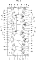
- Fig. 1 is a developed view of a tread part 2 of a tire 1 illustrating an embodiment of the present invention.
- the tire 1 of the present embodiment can be used, for example, for various tires such as a pneumatic tire for a passenger car or a vehicle for a heavy load, and a non-pneumatic tire that is not filled with pressurized air.
- the tire 1 of the present embodiment is suitably used as a pneumatic tire for a heavy load.
- the second midpoints (s2) are each a midpoint of a straight line that connects a tire axial direction innermost side point (a2) of the inner side groove edge (3i) and a tire axial direction innermost side point (a4) of the outer side groove edge (3e).
- each shoulder long side portions (4A) and the shoulder short side portions (4B) of each shoulder main groove 4 are specified by a groove center line (4G) of the shoulder main groove 4, the groove center line (4G) being formed by connecting third midpoints (s3) and fourth midpoints (s4) that are alternately formed on the shoulder main groove 4.
- the third midpoints (s3) are each a midpoint of a straight line that connects a tire axial direction outermost side point (b1) of a tire axial direction inner side groove edge (4i) of the shoulder main groove 4 and a tire axial direction outermost side point (b3) of a tire axial direction outer side groove edge (4e) of the shoulder main groove 4.
- the crown main grooves 3 where stone biting is likely to occur are formed such that stones are easily ejected, and the rigidity of the land portions near the shoulder main grooves 4 where slipping is likely to occur is increased, and thus, for example, heel-and-toe wear is largely reduced.
- a ground contact pressure during straight traveling is smaller in the land portions near the shoulder main grooves 4 as compared to the land portions near the crown main grooves 3. Therefore, by specifying the shoulder long-short ratio (Lc/Ld) of the shoulder main grooves 4 to be relatively small, drainage resistance of the shoulder main grooves 4 is reduced and thus wet performance is improved. As a result, wear life performance, anti-stone-biting performance and wet performance are improved in a well-balanced manner.
- the crown long-short ratio (La/Lb) be 1.17 - 1.27.
- the crown long-short ratio (La/Lb) is less than 1.17, the tire circumferential direction rigidity difference of the land portions near the crown main grooves 3 is reduced, and deformation of the land portions becomes small, and thus, stones caught in the crown main grooves 3 are less likely to be ejected.
- the crown long-short ratio (La/Lb) exceeds 1.27, the tire circumferential direction rigidity difference of the land portions becomes excessively large, and thus, for example, center wear is likely to occur, and there is a risk that the wear life performance may deteriorate.
- the shoulder long-short ratio (Lc/Ld) be 1.01 - 1.11.
- the shoulder long-short ratio (Lc/Ld) is less than 1.01, the tire circumferential direction rigidity difference of the land portions near the shoulder main grooves 4 becomes excessively small, and deformation of the land portions becomes small, and thus, there is a risk that stones caught in the shoulder main grooves 4 cannot be ejected.
- the shoulder long-short ratio (Lc/Ld) exceeds 1.11, the tire circumferential direction rigidity difference of the land portions near the shoulder main grooves 4 becomes large, and thus, for example, heel-and-toe wear is likely to occur.
- the shoulder long-short ratio (Lc/Ld) exceeds 1.11, drainage resistance of the shoulder main grooves 4 becomes large, and there is a risk that the wet performance may deteriorate.
- the crown long-short ratio (La/Lb) is less than 1.1 times the shoulder long-short ratio (Lc/Ld)
- the crown long-short ratio (La/Lb) exceeds 1.2 times the shoulder long-short ratio (Lc/Ld)
- the rigidity difference of the land portions near the crown main grooves 3 becomes excessively large, and there is a risk that the wear life performance may deteriorate.
- one pitch (P1) of the zigzag shape of each of the crown main grooves 3 and one pitch (P2) of the zigzag shape of each of the shoulder main grooves 4 be each 28% - 36% of a tread width (TW) (illustrated in Fig. 1 ).
- the "tread width (TW)" is defined as a tire axial direction distance between tread edges (Te, Te) that are respectively ground contact positions of both tire axial direction outermost sides when the tire 1 in a normal state, which refers to a no-load state in which the tire 1 is mounted to a normal rim and is filled with air at a normal internal pressure, is loaded with a normal load and is grounded on a flat surface at a camber angle of 0 degree. Unless otherwise specified, values of dimensions and the like of the parts of the tire are values measured in the normal state.
- normal rim refers to a rim for which standards are set for each tire in a system of standards that includes standards on which the tire is based.
- normal rim refers to a "Standard Rim” in the JATMA standards, a "Design Rim” in the TRA standards, or a "Measuring Rim” in the ETRTO standards.
- normal load refers to a load for which standards are set for each tire in a system of standards that includes the standards on which the tire is based, and refers to a "Maximum Load Capacity" in the JATMA standards, a maximum value published in the table “Tire Load Limits at Various Cold Inflation Pressures” in the TRA standards, or a “Load Capacity” in the ETRTO standards.
- block-like protruding portions 11 are formed on a groove bottom (3s).
- the protruding portions 11 can reduce damage to the groove bottom (3s) due to stone biting.
- the protruding portions 11 are provided along the groove center line (3G).
- an angle ( ⁇ 2) of the shoulder main grooves 4 with respect to the tire circumferential direction be smaller than the angle ( ⁇ 1) of the crown main grooves 3 (illustrated in Fig. 3 ).
- the angle ( ⁇ 2) of the shoulder main grooves 4 be 8 - 28 degrees.
- the angles ( ⁇ 1, ⁇ 2) are respectively angles of the groove center lines (3G, 4G) of the main grooves 3, 4.
- a groove width (W1) of the crown main grooves 3 be smaller than a groove width (W2) of the shoulder main grooves 4.
- the groove width (W1) of the crown main grooves 3 is larger than the groove width (W2) of the shoulder main grooves 4, there is a risk that, during straight traveling, rigidity of land portions between the crown main grooves 3, 3, where the ground contact pressure is high, is insufficient, and the wear life performance deteriorates.
- the groove width (W1) of the crown main grooves 3 is excessively smaller than the groove width (W2) of the shoulder main grooves 4, there is a risk that the anti-stone-biting performance may deteriorate.
- the groove width (W1) of the crown main grooves 3 be 85% - 95% of the groove width (W2) of the shoulder main grooves 4.
- a groove depth (not illustrated in the drawings) of each of the crown main grooves 3 and the shoulder main grooves 4 be 10 - 20 mm.
- crown transverse grooves 5, middle transverse grooves 6 and shoulder transverse grooves 7 are provided in the tread part 2 of the present embodiment.
- the crown transverse grooves 5 extend between the crown main grooves 3, 3.
- the middle transverse grooves 6 extend between the crown main grooves 3 and the shoulder main grooves 4.
- the shoulder transverse grooves 7 extend between the shoulder main grooves 4 and the tread edges (Te).
- a crown block row (8R), middle block rows (9R), and shoulder block rows (10R) are formed.
- the crown block row (8R) is a land portion in which multiple crown blocks 8, which are divided by the pair of crown main grooves 3, 3 and the crown transverse grooves 5, are arranged in the tire circumferential direction.
- the middle block rows (9R) are land portions in which multiple middle blocks 9, which are divided by the crown main grooves 3, the shoulder main grooves 4 and the middle transverse grooves 6, are arranged in the tire circumferential direction.
- the shoulder block rows (10R) are land portions in which multiple shoulder blocks 10, which are divided by the tread edges (Te), the shoulder main grooves 4 and the shoulder transverse grooves 7, are arranged in the tire circumferential direction.
- the crown transverse grooves 5 of the present embodiment are formed such that both ends of each of the crown transverse grooves 5 include the points (a2). That is, the crown transverse grooves 5 are formed to each have a small length in the tire axial direction.
- Such crown transverse grooves 5 can improve anti-stone-biting performance, and allow rigidity of the crown blocks 8 to be maintained high and can suppress wear occurring to the crown blocks 8.
- the crown transverse grooves 5 and the middle transverse grooves 6 each extend linearly. As a result, the rigidity of the middle blocks 9 and the crown blocks 8 is maintained high and thus the wear life performance is further improved. It is also possible that the middle transverse grooves 6 and the crown transverse grooves 5 are each formed, for example, to have an arc-shaped groove edge.
- the middle transverse grooves 6 are inclined in an opposite direction to the crown transverse grooves 5.
- the middle transverse grooves 6 are inclined leftward and upward, and the crown transverse grooves 5 are inclined rightward and upward.
- the shoulder transverse grooves 7 of the present embodiment each include a constant width portion (7A) and a gradually increasing portion (7B).
- the constant width portion (7A) extends from one of the shoulder main grooves 4 to a tire axial direction outer side and has a constant groove width.
- the gradually increasing portion (7B) connects a tire axial direction outer end (7e) of the constant width portion (7A) and one of the tread edges (Te) and has a groove width that gradually increases toward a tire axial direction outer side.
- a groove depth (not illustrated in the drawings) of each of the shoulder transverse grooves 7 is 10% - 40% of the groove depth of each of the shoulder main grooves 4.
- Such shoulder transverse grooves 7 can increase rigidity of the shoulder block row (10R), on which a large lateral force acts during turning, and suppress heel-and-toe wear.
- the crown blocks 8 and the middle blocks 9 are each formed in a hexagonal shape having a large barrel-like tire circumferential direction central portion.
- Such crown blocks 8 and middle blocks 9 ensure high rigidity of the tire circumferential direction central portions. Therefore, deformation of the blocks 8, 9 in the tire axial direction is suppressed and thus the wear life performance is improved.
- a tire axial direction maximum width (Wc) of the crown blocks 8 is larger than a tire axial direction maximum width (Wm) of the middle blocks 9.
- Wc tire axial direction maximum width
- Wm tire axial direction maximum width
- the rigidity of the crown blocks 8 becomes excessively large, deformation of the crown blocks 8 is largely suppressed, and there is a risk that the anti-stone-biting performance may deteriorate.
- the tire axial direction maximum width (Wc) of the crown blocks 8 be more than 1.00 times and equal to or less than 1.05 times the tire axial direction maximum width (Wm) of the middle blocks 9.
- the maximum width (Wc) of the crown blocks 8 be 15% - 25% of the tread width (TW).
- Crown sipes 15 and middle sipes 16 extending in the tire axial direction are respectively provided in the crown blocks 8 and the middle blocks 9. Such crown sipes 15 and middle sipes 16 promote deformation of the blocks 8, 9 and improve the anti-stone-biting performance.
- the crown sipes 15 and the middle sipes 16 respectively extend across the blocks 8, 9 in the tire axial direction.
- a pair of crown block pieces (8a, 8a) are respectively formed on both tire circumferential direction sides of the crown sipe 15.
- a pair of middle block pieces (9a, 9a) are respectively formed on both tire circumferential direction sides of the middle sipe 16.
- the crown sipes 15 and the middle sipes 16 are respectively provided in tire maximum width position vicinities of the blocks 8, 9. As a result, the blocks 8, 9 effectively deform, and the anti-stone-biting performance is improved.
- the sipes are provided in tire maximum width position vicinities means that a tire circumferential direction distance (L1) between a point (a1) and an outer end (15e) of a crown sipe 15 adjacent to the point (a1) is 40% or less of the groove width (W3) of the crown transverse grooves 5.
- each of the middle sipes 16 extends in a first region (R1) formed by projecting an adjacent crown transverse groove 5 on a tire axial direction outer side of the crown transverse groove 5.
- first region (R1) formed by projecting an adjacent crown transverse groove 5 on a tire axial direction outer side of the crown transverse groove 5.
- each of the crown sipes 15 of the present embodiment extend in a second region (R2) formed by projecting an adjacent middle transverse groove 6 on a tire axial direction inner side of the middle transverse groove 6.
- angles ( ⁇ 1, 02) of the crown sipes 15 and the middle sipes 16 with respect to the tire axial direction be each 5 degrees or more and less than 15 degrees.
- Such crown sipes 15 and middle sipes 16 suppress decrease in tire axial direction rigidity of the block pieces (8a, 9a), and help the crown block pieces (8a, 8a) and the middle block pieces (9a, 9a) to support each other when in contact with a road surface. Therefore, excessive deformation of the block pieces (8a, 9a) is suppressed, and the wear life performance is effectively improved.
- the angle ( ⁇ 1) of the crown sipes 15 be the same as the angle ( ⁇ 3) of the crown transverse grooves 5. It is desirable that the angle ( ⁇ 2) of the middle sipes 16 be the same as the angle ( ⁇ 4) of the middle transverse grooves 6.
- the crown sipes 15 and the middle sipes 16 each extend in a zigzag shape. As a result, excessive deformation of the crown blocks 8 and the middle blocks 9 is suppressed and thus the wear life performance is maintained high.
- the crown sipes 15 and the middle sipes 16 are not limited to having such a shape.
- the sipes may also each extend in a linear or wavy shape.
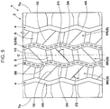
- Fig. 5 is a developed view of a tread part 2 illustrating another embodiment of the present invention.
- a tread pattern is the same as that illustrated in Fig. 1 except for the shape of the crown sipes 15 and the middle sipes 16. Therefore, description about structures other than the crown sipes 15 and the middle sipes 16 is omitted.
- the tire axial direction angles ( ⁇ 1, ⁇ 2) of the crown sipes 15 and the middle sipes 16 are each 15 - 75 degrees.
- Such crown sipes 15 and middle sipes 16 allow a large edge effect in the tire circumferential direction to be achieved and allow a water film between the crown blocks 8 and middle blocks 9 and a tread surface to be effectively discharged.
- angles ( ⁇ 1, ⁇ 2) of the crown sipes 15 and the middle sipes 16 are large, the rigidity of the crown blocks 8 and the middle blocks 9 is largely decreased.
- angles ( ⁇ 1, ⁇ 2) of the crown sipes 15 and the middle sipes 16 are small, improvement in the wet performance is reduced. From this point of view, the angles ( ⁇ 1, ⁇ 2) of the crown sipes 15 and the middle sipes 16 with respect to the tire axial direction are more preferably 35 - 55 degrees.
- the crown sipes 15 each extend between crown short side portions (3B, 3B).
- the rigidity of the crown blocks 8, where a large ground contact pressure acts can be effectively decreased and thus, deformation of the crown blocks 8 near the crown short side portions (3B) is facilitated and the anti-stone-biting performance is improved.
- the middle sipes 16 each extend between a crown long side portion (3A) and a shoulder long side portion (4A). That is, tire axial direction inner ends (16i) of the middle sipes 16 and outer ends (15e) of the crown sipes 15 are largely separated in the tire circumferential direction, and thus, excessive deformation of the blocks 8, 9 is suppressed. As a result, deterioration of the wear life performance is suppressed. In this way, in this embodiment, while high wet performance is achieved, the wear life performance and the anti-stone-biting performance are improved in a well-balanced manner.
- the prototyped tires were mounted to all wheels of a vehicle under the following conditions, and were caused to travel on a circuit course of a gravel road surface for 2000 km at a speed of 40 - 60 km/h. Thereafter, a total number of stones caught in the crown main grooves and the shoulder main grooves was examined. The result was expressed as an index number with a value of Comparative Example 1 as 100. A smaller index number indicates a better anti-stone-biting performance.
- the prototyped tires were further caused to travel on the same test course for 5000 km, and then, an average of groove depths at eight places on a tire circumference in each of the crown main grooves and shoulder main grooves was calculated, and the result was expressed as an index number with a value of Comparative Example 1 as 100. A larger index number indicates a better wear life performance.
- a test driver drove the above vehicle on a test course of a wet road surface with a water depth of 1 mm, and driving characteristics relating to a driving force and a braking force at the time of driving were evaluated based on a sensory evaluation by the test driver.
- the result was expressed as a score with a value of Comparative Example 1 as 100. A larger score indicates a better wet performance.
- a tire 1 in which a crown main groove 3 and a shoulder main groove 4 are provided.
- the crown main groove 3 is formed in a zigzag shape in which crown long side portions (3A) and crown short side portions (3B) are alternately formed in a tire circumferential direction.
- the shoulder main groove 4 is formed in a zigzag shape in which shoulder long side portions (4A) and shoulder short side portions (4B) are alternately formed in the tire circumferential direction.
Landscapes
- Engineering & Computer Science (AREA)
- Mechanical Engineering (AREA)
- Tires In General (AREA)
Applications Claiming Priority (1)
| Application Number | Priority Date | Filing Date | Title |
|---|---|---|---|
| JP2016042414A JP6665594B2 (ja) | 2016-03-04 | 2016-03-04 | タイヤ |
Publications (2)
| Publication Number | Publication Date |
|---|---|
| EP3213932A1 true EP3213932A1 (fr) | 2017-09-06 |
| EP3213932B1 EP3213932B1 (fr) | 2019-10-02 |
Family
ID=58094282
Family Applications (1)
| Application Number | Title | Priority Date | Filing Date |
|---|---|---|---|
| EP17156814.0A Active EP3213932B1 (fr) | 2016-03-04 | 2017-02-20 | Pneumatique |
Country Status (4)
| Country | Link |
|---|---|
| US (1) | US10654320B2 (fr) |
| EP (1) | EP3213932B1 (fr) |
| JP (1) | JP6665594B2 (fr) |
| CN (1) | CN107150557B (fr) |
Cited By (3)
| Publication number | Priority date | Publication date | Assignee | Title |
|---|---|---|---|---|
| EP3838626A1 (fr) * | 2019-12-16 | 2021-06-23 | Sumitomo Rubber Industries, Ltd. | Pneumatique |
| US12077017B2 (en) | 2018-11-27 | 2024-09-03 | The Yokohama Rubber Co., Ltd. | Pneumatic tire |
| CN119795794A (zh) * | 2024-12-30 | 2025-04-11 | 风神轮胎股份有限公司 | 一种矿用长运距轮胎花纹及轮胎 |
Families Citing this family (13)
| Publication number | Priority date | Publication date | Assignee | Title |
|---|---|---|---|---|
| USD811992S1 (en) * | 2016-05-18 | 2018-03-06 | Compagnie Generale Des Etablissements Michelin | Tire tread |
| CA175882S (en) * | 2017-01-16 | 2018-02-20 | Hankook Tire Co Ltd | Tire |
| JP6933119B2 (ja) | 2017-12-13 | 2021-09-08 | 住友ゴム工業株式会社 | タイヤ |
| US11999199B2 (en) * | 2018-09-28 | 2024-06-04 | The Yokohama Rubber Co., Ltd. | Pneumatic tire |
| JP7126964B2 (ja) * | 2019-02-18 | 2022-08-29 | 株式会社ブリヂストン | 二輪車用タイヤ |
| JP7367543B2 (ja) * | 2020-01-28 | 2023-10-24 | 住友ゴム工業株式会社 | タイヤ |
| DE102021105423B4 (de) | 2020-03-31 | 2026-03-19 | The Yokohama Rubber Co., Ltd. | Reifen |
| DE102021105422A1 (de) | 2020-03-31 | 2021-09-30 | The Yokohama Rubber Co., Ltd. | R e i f e n |
| JP7492124B2 (ja) * | 2020-04-30 | 2024-05-29 | 横浜ゴム株式会社 | タイヤ |
| USD982508S1 (en) | 2021-03-01 | 2023-04-04 | Compagnie Generale Des Etablissements Michelin | Tire |
| JP7746815B2 (ja) * | 2021-11-11 | 2025-10-01 | 住友ゴム工業株式会社 | タイヤ |
| USD1073589S1 (en) | 2023-03-09 | 2025-05-06 | Compagnie Generale Des Etablissements Michelin | Tire |
| USD1095398S1 (en) | 2024-01-19 | 2025-09-30 | Compagnie Generale Des Etablissements Michelin | Tire |
Citations (4)
| Publication number | Priority date | Publication date | Assignee | Title |
|---|---|---|---|---|
| EP2610080A1 (fr) * | 2011-12-26 | 2013-07-03 | Sumitomo Rubber Industries, Ltd. | Pneu renforcé |
| JP2013189099A (ja) | 2012-03-14 | 2013-09-26 | Bridgestone Corp | 空気入りタイヤ |
| US20150352903A1 (en) * | 2013-02-01 | 2015-12-10 | Bridgestone Corporation | Pneumatic tire |
| EP3017965A1 (fr) * | 2013-07-02 | 2016-05-11 | Bridgestone Corporation | Pneumatique |
Family Cites Families (8)
| Publication number | Priority date | Publication date | Assignee | Title |
|---|---|---|---|---|
| US7762297B2 (en) * | 2004-11-18 | 2010-07-27 | Sumitomo Rubber Industries, Ltd. | Heavy duty pneumatic tire |
| JP5071924B2 (ja) * | 2006-12-14 | 2012-11-14 | 株式会社ブリヂストン | 空気入りタイヤ |
| EP2390113B1 (fr) * | 2009-01-26 | 2014-07-16 | Bridgestone Corporation | Pneu |
| JP5227355B2 (ja) * | 2010-03-19 | 2013-07-03 | 住友ゴム工業株式会社 | 重荷重用タイヤ |
| WO2013040361A2 (fr) * | 2011-09-14 | 2013-03-21 | Flodesign Wind Turbine Corp. | Système de protection contre la foudre de turbine à fluide |
| JP5406949B2 (ja) * | 2012-01-16 | 2014-02-05 | 住友ゴム工業株式会社 | 重荷重用空気入りタイヤ |
| DE102012111116A1 (de) * | 2012-11-19 | 2014-05-22 | Continental Reifen Deutschland Gmbh | Fahrzeugluftreifen |
| JP2014162429A (ja) * | 2013-02-27 | 2014-09-08 | Bridgestone Corp | 空気入りタイヤ |
-
2016
- 2016-03-04 JP JP2016042414A patent/JP6665594B2/ja active Active
-
2017
- 2017-02-17 CN CN201710086100.4A patent/CN107150557B/zh active Active
- 2017-02-20 EP EP17156814.0A patent/EP3213932B1/fr active Active
- 2017-02-23 US US15/440,005 patent/US10654320B2/en active Active
Patent Citations (4)
| Publication number | Priority date | Publication date | Assignee | Title |
|---|---|---|---|---|
| EP2610080A1 (fr) * | 2011-12-26 | 2013-07-03 | Sumitomo Rubber Industries, Ltd. | Pneu renforcé |
| JP2013189099A (ja) | 2012-03-14 | 2013-09-26 | Bridgestone Corp | 空気入りタイヤ |
| US20150352903A1 (en) * | 2013-02-01 | 2015-12-10 | Bridgestone Corporation | Pneumatic tire |
| EP3017965A1 (fr) * | 2013-07-02 | 2016-05-11 | Bridgestone Corporation | Pneumatique |
Cited By (3)
| Publication number | Priority date | Publication date | Assignee | Title |
|---|---|---|---|---|
| US12077017B2 (en) | 2018-11-27 | 2024-09-03 | The Yokohama Rubber Co., Ltd. | Pneumatic tire |
| EP3838626A1 (fr) * | 2019-12-16 | 2021-06-23 | Sumitomo Rubber Industries, Ltd. | Pneumatique |
| CN119795794A (zh) * | 2024-12-30 | 2025-04-11 | 风神轮胎股份有限公司 | 一种矿用长运距轮胎花纹及轮胎 |
Also Published As
| Publication number | Publication date |
|---|---|
| EP3213932B1 (fr) | 2019-10-02 |
| CN107150557B (zh) | 2021-01-22 |
| US10654320B2 (en) | 2020-05-19 |
| CN107150557A (zh) | 2017-09-12 |
| JP2017154708A (ja) | 2017-09-07 |
| US20170253088A1 (en) | 2017-09-07 |
| JP6665594B2 (ja) | 2020-03-13 |
Similar Documents
| Publication | Publication Date | Title |
|---|---|---|
| EP3213932B1 (fr) | Pneumatique | |
| US10894446B2 (en) | Tire | |
| US10836215B2 (en) | Tire | |
| JP5454602B2 (ja) | 空気入りタイヤ | |
| EP3040216B1 (fr) | Pneu | |
| US20160144668A1 (en) | Pneumatic tire | |
| JP2010241267A (ja) | 空気入りタイヤ | |
| KR20120120022A (ko) | 공기 타이어 | |
| CN112644227B (zh) | 轮胎 | |
| CN110509724B (zh) | 轮胎 | |
| EP3444131B1 (fr) | Pneumatique | |
| CN108068558A (zh) | 轮胎 | |
| US20150151589A1 (en) | Pneumatic tire | |
| JP7587130B2 (ja) | 空気入りタイヤ | |
| JPWO2020153011A1 (ja) | 空気入りタイヤ | |
| CN110341389B (zh) | 轮胎 | |
| JP4358572B2 (ja) | オフザロードタイヤ | |
| CN110091676B (zh) | 轮胎 | |
| CN112829520B (zh) | 轮胎 | |
| US10195906B2 (en) | Tire | |
| JP7553842B2 (ja) | タイヤ | |
| JP2004345457A (ja) | 空気入りタイヤ | |
| US11724548B2 (en) | Tire | |
| CN113022231B (zh) | 充气轮胎 | |
| AU2019339359A1 (en) | Pneumatic tire |
Legal Events
| Date | Code | Title | Description |
|---|---|---|---|
| PUAI | Public reference made under article 153(3) epc to a published international application that has entered the european phase |
Free format text: ORIGINAL CODE: 0009012 |
|
| STAA | Information on the status of an ep patent application or granted ep patent |
Free format text: STATUS: THE APPLICATION HAS BEEN PUBLISHED |
|
| AK | Designated contracting states |
Kind code of ref document: A1 Designated state(s): AL AT BE BG CH CY CZ DE DK EE ES FI FR GB GR HR HU IE IS IT LI LT LU LV MC MK MT NL NO PL PT RO RS SE SI SK SM TR |
|
| AX | Request for extension of the european patent |
Extension state: BA ME |
|
| STAA | Information on the status of an ep patent application or granted ep patent |
Free format text: STATUS: REQUEST FOR EXAMINATION WAS MADE |
|
| 17P | Request for examination filed |
Effective date: 20170911 |
|
| STAA | Information on the status of an ep patent application or granted ep patent |
Free format text: STATUS: EXAMINATION IS IN PROGRESS |
|
| 17Q | First examination report despatched |
Effective date: 20180320 |
|
| GRAP | Despatch of communication of intention to grant a patent |
Free format text: ORIGINAL CODE: EPIDOSNIGR1 |
|
| STAA | Information on the status of an ep patent application or granted ep patent |
Free format text: STATUS: GRANT OF PATENT IS INTENDED |
|
| INTG | Intention to grant announced |
Effective date: 20190506 |
|
| GRAS | Grant fee paid |
Free format text: ORIGINAL CODE: EPIDOSNIGR3 |
|
| GRAA | (expected) grant |
Free format text: ORIGINAL CODE: 0009210 |
|
| STAA | Information on the status of an ep patent application or granted ep patent |
Free format text: STATUS: THE PATENT HAS BEEN GRANTED |
|
| AK | Designated contracting states |
Kind code of ref document: B1 Designated state(s): AL AT BE BG CH CY CZ DE DK EE ES FI FR GB GR HR HU IE IS IT LI LT LU LV MC MK MT NL NO PL PT RO RS SE SI SK SM TR |
|
| REG | Reference to a national code |
Ref country code: GB Ref legal event code: FG4D |
|
| REG | Reference to a national code |
Ref country code: CH Ref legal event code: EP Ref country code: AT Ref legal event code: REF Ref document number: 1185782 Country of ref document: AT Kind code of ref document: T Effective date: 20191015 |
|
| REG | Reference to a national code |
Ref country code: DE Ref legal event code: R096 Ref document number: 602017007367 Country of ref document: DE |
|
| REG | Reference to a national code |
Ref country code: IE Ref legal event code: FG4D |
|
| REG | Reference to a national code |
Ref country code: NL Ref legal event code: MP Effective date: 20191002 |
|
| REG | Reference to a national code |
Ref country code: LT Ref legal event code: MG4D |
|
| REG | Reference to a national code |
Ref country code: AT Ref legal event code: MK05 Ref document number: 1185782 Country of ref document: AT Kind code of ref document: T Effective date: 20191002 |
|
| PG25 | Lapsed in a contracting state [announced via postgrant information from national office to epo] |
Ref country code: AT Free format text: LAPSE BECAUSE OF FAILURE TO SUBMIT A TRANSLATION OF THE DESCRIPTION OR TO PAY THE FEE WITHIN THE PRESCRIBED TIME-LIMIT Effective date: 20191002 Ref country code: PT Free format text: LAPSE BECAUSE OF FAILURE TO SUBMIT A TRANSLATION OF THE DESCRIPTION OR TO PAY THE FEE WITHIN THE PRESCRIBED TIME-LIMIT Effective date: 20200203 Ref country code: NO Free format text: LAPSE BECAUSE OF FAILURE TO SUBMIT A TRANSLATION OF THE DESCRIPTION OR TO PAY THE FEE WITHIN THE PRESCRIBED TIME-LIMIT Effective date: 20200102 Ref country code: LT Free format text: LAPSE BECAUSE OF FAILURE TO SUBMIT A TRANSLATION OF THE DESCRIPTION OR TO PAY THE FEE WITHIN THE PRESCRIBED TIME-LIMIT Effective date: 20191002 Ref country code: FI Free format text: LAPSE BECAUSE OF FAILURE TO SUBMIT A TRANSLATION OF THE DESCRIPTION OR TO PAY THE FEE WITHIN THE PRESCRIBED TIME-LIMIT Effective date: 20191002 Ref country code: BG Free format text: LAPSE BECAUSE OF FAILURE TO SUBMIT A TRANSLATION OF THE DESCRIPTION OR TO PAY THE FEE WITHIN THE PRESCRIBED TIME-LIMIT Effective date: 20200102 Ref country code: NL Free format text: LAPSE BECAUSE OF FAILURE TO SUBMIT A TRANSLATION OF THE DESCRIPTION OR TO PAY THE FEE WITHIN THE PRESCRIBED TIME-LIMIT Effective date: 20191002 Ref country code: SE Free format text: LAPSE BECAUSE OF FAILURE TO SUBMIT A TRANSLATION OF THE DESCRIPTION OR TO PAY THE FEE WITHIN THE PRESCRIBED TIME-LIMIT Effective date: 20191002 Ref country code: LV Free format text: LAPSE BECAUSE OF FAILURE TO SUBMIT A TRANSLATION OF THE DESCRIPTION OR TO PAY THE FEE WITHIN THE PRESCRIBED TIME-LIMIT Effective date: 20191002 Ref country code: PL Free format text: LAPSE BECAUSE OF FAILURE TO SUBMIT A TRANSLATION OF THE DESCRIPTION OR TO PAY THE FEE WITHIN THE PRESCRIBED TIME-LIMIT Effective date: 20191002 Ref country code: GR Free format text: LAPSE BECAUSE OF FAILURE TO SUBMIT A TRANSLATION OF THE DESCRIPTION OR TO PAY THE FEE WITHIN THE PRESCRIBED TIME-LIMIT Effective date: 20200103 |
|
| PG25 | Lapsed in a contracting state [announced via postgrant information from national office to epo] |
Ref country code: HR Free format text: LAPSE BECAUSE OF FAILURE TO SUBMIT A TRANSLATION OF THE DESCRIPTION OR TO PAY THE FEE WITHIN THE PRESCRIBED TIME-LIMIT Effective date: 20191002 Ref country code: IS Free format text: LAPSE BECAUSE OF FAILURE TO SUBMIT A TRANSLATION OF THE DESCRIPTION OR TO PAY THE FEE WITHIN THE PRESCRIBED TIME-LIMIT Effective date: 20200224 Ref country code: RS Free format text: LAPSE BECAUSE OF FAILURE TO SUBMIT A TRANSLATION OF THE DESCRIPTION OR TO PAY THE FEE WITHIN THE PRESCRIBED TIME-LIMIT Effective date: 20191002 Ref country code: CZ Free format text: LAPSE BECAUSE OF FAILURE TO SUBMIT A TRANSLATION OF THE DESCRIPTION OR TO PAY THE FEE WITHIN THE PRESCRIBED TIME-LIMIT Effective date: 20191002 |
|
| PG25 | Lapsed in a contracting state [announced via postgrant information from national office to epo] |
Ref country code: AL Free format text: LAPSE BECAUSE OF FAILURE TO SUBMIT A TRANSLATION OF THE DESCRIPTION OR TO PAY THE FEE WITHIN THE PRESCRIBED TIME-LIMIT Effective date: 20191002 |
|
| REG | Reference to a national code |
Ref country code: DE Ref legal event code: R097 Ref document number: 602017007367 Country of ref document: DE |
|
| PG2D | Information on lapse in contracting state deleted |
Ref country code: IS |
|
| PG25 | Lapsed in a contracting state [announced via postgrant information from national office to epo] |
Ref country code: EE Free format text: LAPSE BECAUSE OF FAILURE TO SUBMIT A TRANSLATION OF THE DESCRIPTION OR TO PAY THE FEE WITHIN THE PRESCRIBED TIME-LIMIT Effective date: 20191002 Ref country code: RO Free format text: LAPSE BECAUSE OF FAILURE TO SUBMIT A TRANSLATION OF THE DESCRIPTION OR TO PAY THE FEE WITHIN THE PRESCRIBED TIME-LIMIT Effective date: 20191002 Ref country code: DK Free format text: LAPSE BECAUSE OF FAILURE TO SUBMIT A TRANSLATION OF THE DESCRIPTION OR TO PAY THE FEE WITHIN THE PRESCRIBED TIME-LIMIT Effective date: 20191002 Ref country code: IS Free format text: LAPSE BECAUSE OF FAILURE TO SUBMIT A TRANSLATION OF THE DESCRIPTION OR TO PAY THE FEE WITHIN THE PRESCRIBED TIME-LIMIT Effective date: 20200202 |
|
| PLBE | No opposition filed within time limit |
Free format text: ORIGINAL CODE: 0009261 |
|
| STAA | Information on the status of an ep patent application or granted ep patent |
Free format text: STATUS: NO OPPOSITION FILED WITHIN TIME LIMIT |
|
| PG25 | Lapsed in a contracting state [announced via postgrant information from national office to epo] |
Ref country code: SM Free format text: LAPSE BECAUSE OF FAILURE TO SUBMIT A TRANSLATION OF THE DESCRIPTION OR TO PAY THE FEE WITHIN THE PRESCRIBED TIME-LIMIT Effective date: 20191002 Ref country code: SK Free format text: LAPSE BECAUSE OF FAILURE TO SUBMIT A TRANSLATION OF THE DESCRIPTION OR TO PAY THE FEE WITHIN THE PRESCRIBED TIME-LIMIT Effective date: 20191002 Ref country code: IT Free format text: LAPSE BECAUSE OF FAILURE TO SUBMIT A TRANSLATION OF THE DESCRIPTION OR TO PAY THE FEE WITHIN THE PRESCRIBED TIME-LIMIT Effective date: 20191002 |
|
| 26N | No opposition filed |
Effective date: 20200703 |
|
| REG | Reference to a national code |
Ref country code: CH Ref legal event code: PL |
|
| REG | Reference to a national code |
Ref country code: BE Ref legal event code: MM Effective date: 20200229 |
|
| PG25 | Lapsed in a contracting state [announced via postgrant information from national office to epo] |
Ref country code: ES Free format text: LAPSE BECAUSE OF FAILURE TO SUBMIT A TRANSLATION OF THE DESCRIPTION OR TO PAY THE FEE WITHIN THE PRESCRIBED TIME-LIMIT Effective date: 20191002 Ref country code: LU Free format text: LAPSE BECAUSE OF NON-PAYMENT OF DUE FEES Effective date: 20200220 Ref country code: MC Free format text: LAPSE BECAUSE OF FAILURE TO SUBMIT A TRANSLATION OF THE DESCRIPTION OR TO PAY THE FEE WITHIN THE PRESCRIBED TIME-LIMIT Effective date: 20191002 |
|
| PG25 | Lapsed in a contracting state [announced via postgrant information from national office to epo] |
Ref country code: SI Free format text: LAPSE BECAUSE OF FAILURE TO SUBMIT A TRANSLATION OF THE DESCRIPTION OR TO PAY THE FEE WITHIN THE PRESCRIBED TIME-LIMIT Effective date: 20191002 Ref country code: CH Free format text: LAPSE BECAUSE OF NON-PAYMENT OF DUE FEES Effective date: 20200229 Ref country code: LI Free format text: LAPSE BECAUSE OF NON-PAYMENT OF DUE FEES Effective date: 20200229 |
|
| PG25 | Lapsed in a contracting state [announced via postgrant information from national office to epo] |
Ref country code: IE Free format text: LAPSE BECAUSE OF NON-PAYMENT OF DUE FEES Effective date: 20200220 |
|
| PG25 | Lapsed in a contracting state [announced via postgrant information from national office to epo] |
Ref country code: BE Free format text: LAPSE BECAUSE OF NON-PAYMENT OF DUE FEES Effective date: 20200229 |
|
| GBPC | Gb: european patent ceased through non-payment of renewal fee |
Effective date: 20210220 |
|
| PG25 | Lapsed in a contracting state [announced via postgrant information from national office to epo] |
Ref country code: GB Free format text: LAPSE BECAUSE OF NON-PAYMENT OF DUE FEES Effective date: 20210220 |
|
| PG25 | Lapsed in a contracting state [announced via postgrant information from national office to epo] |
Ref country code: TR Free format text: LAPSE BECAUSE OF FAILURE TO SUBMIT A TRANSLATION OF THE DESCRIPTION OR TO PAY THE FEE WITHIN THE PRESCRIBED TIME-LIMIT Effective date: 20191002 Ref country code: MT Free format text: LAPSE BECAUSE OF FAILURE TO SUBMIT A TRANSLATION OF THE DESCRIPTION OR TO PAY THE FEE WITHIN THE PRESCRIBED TIME-LIMIT Effective date: 20191002 Ref country code: CY Free format text: LAPSE BECAUSE OF FAILURE TO SUBMIT A TRANSLATION OF THE DESCRIPTION OR TO PAY THE FEE WITHIN THE PRESCRIBED TIME-LIMIT Effective date: 20191002 |
|
| PG25 | Lapsed in a contracting state [announced via postgrant information from national office to epo] |
Ref country code: MK Free format text: LAPSE BECAUSE OF FAILURE TO SUBMIT A TRANSLATION OF THE DESCRIPTION OR TO PAY THE FEE WITHIN THE PRESCRIBED TIME-LIMIT Effective date: 20191002 |
|
| P01 | Opt-out of the competence of the unified patent court (upc) registered |
Effective date: 20230510 |
|
| PGFP | Annual fee paid to national office [announced via postgrant information from national office to epo] |
Ref country code: FR Payment date: 20251231 Year of fee payment: 10 |
|
| PGFP | Annual fee paid to national office [announced via postgrant information from national office to epo] |
Ref country code: DE Payment date: 20251230 Year of fee payment: 10 |