EP3214014B1 - Récipient pour seringues - Google Patents
Récipient pour seringues Download PDFInfo
- Publication number
- EP3214014B1 EP3214014B1 EP15854713.3A EP15854713A EP3214014B1 EP 3214014 B1 EP3214014 B1 EP 3214014B1 EP 15854713 A EP15854713 A EP 15854713A EP 3214014 B1 EP3214014 B1 EP 3214014B1
- Authority
- EP
- European Patent Office
- Prior art keywords
- cylinder
- lid
- syringe
- container
- mounting cylinder
- Prior art date
- Legal status (The legal status is an assumption and is not a legal conclusion. Google has not performed a legal analysis and makes no representation as to the accuracy of the status listed.)
- Active
Links
Images



Classifications
-
- A—HUMAN NECESSITIES
- A61—MEDICAL OR VETERINARY SCIENCE; HYGIENE
- A61J—CONTAINERS SPECIALLY ADAPTED FOR MEDICAL OR PHARMACEUTICAL PURPOSES; DEVICES OR METHODS SPECIALLY ADAPTED FOR BRINGING PHARMACEUTICAL PRODUCTS INTO PARTICULAR PHYSICAL OR ADMINISTERING FORMS; DEVICES FOR ADMINISTERING FOOD OR MEDICINES ORALLY; BABY COMFORTERS; DEVICES FOR RECEIVING SPITTLE
- A61J1/00—Containers specially adapted for medical or pharmaceutical purposes
- A61J1/14—Details; Accessories therefor
- A61J1/20—Arrangements for transferring or mixing fluids, e.g. from vial to syringe
-
- A—HUMAN NECESSITIES
- A61—MEDICAL OR VETERINARY SCIENCE; HYGIENE
- A61J—CONTAINERS SPECIALLY ADAPTED FOR MEDICAL OR PHARMACEUTICAL PURPOSES; DEVICES OR METHODS SPECIALLY ADAPTED FOR BRINGING PHARMACEUTICAL PRODUCTS INTO PARTICULAR PHYSICAL OR ADMINISTERING FORMS; DEVICES FOR ADMINISTERING FOOD OR MEDICINES ORALLY; BABY COMFORTERS; DEVICES FOR RECEIVING SPITTLE
- A61J1/00—Containers specially adapted for medical or pharmaceutical purposes
- A61J1/14—Details; Accessories therefor
- A61J1/20—Arrangements for transferring or mixing fluids, e.g. from vial to syringe
- A61J1/2003—Accessories used in combination with means for transfer or mixing of fluids, e.g. for activating fluid flow, separating fluids, filtering fluid or venting
-
- A—HUMAN NECESSITIES
- A61—MEDICAL OR VETERINARY SCIENCE; HYGIENE
- A61J—CONTAINERS SPECIALLY ADAPTED FOR MEDICAL OR PHARMACEUTICAL PURPOSES; DEVICES OR METHODS SPECIALLY ADAPTED FOR BRINGING PHARMACEUTICAL PRODUCTS INTO PARTICULAR PHYSICAL OR ADMINISTERING FORMS; DEVICES FOR ADMINISTERING FOOD OR MEDICINES ORALLY; BABY COMFORTERS; DEVICES FOR RECEIVING SPITTLE
- A61J1/00—Containers specially adapted for medical or pharmaceutical purposes
- A61J1/14—Details; Accessories therefor
- A61J1/20—Arrangements for transferring or mixing fluids, e.g. from vial to syringe
- A61J1/2003—Accessories used in combination with means for transfer or mixing of fluids, e.g. for activating fluid flow, separating fluids, filtering fluid or venting
- A61J1/202—Separating means
- A61J1/2037—Separating means having valve means
-
- A—HUMAN NECESSITIES
- A61—MEDICAL OR VETERINARY SCIENCE; HYGIENE
- A61M—DEVICES FOR INTRODUCING MEDIA INTO, OR ONTO, THE BODY; DEVICES FOR TRANSDUCING BODY MEDIA OR FOR TAKING MEDIA FROM THE BODY; DEVICES FOR PRODUCING OR ENDING SLEEP OR STUPOR
- A61M5/00—Devices for bringing media into the body in a subcutaneous, intra-vascular or intramuscular way; Accessories therefor, e.g. filling or cleaning devices, arm-rests
- A61M5/178—Syringes
- A61M5/31—Details
- A61M5/3129—Syringe barrels
-
- A—HUMAN NECESSITIES
- A61—MEDICAL OR VETERINARY SCIENCE; HYGIENE
- A61M—DEVICES FOR INTRODUCING MEDIA INTO, OR ONTO, THE BODY; DEVICES FOR TRANSDUCING BODY MEDIA OR FOR TAKING MEDIA FROM THE BODY; DEVICES FOR PRODUCING OR ENDING SLEEP OR STUPOR
- A61M5/00—Devices for bringing media into the body in a subcutaneous, intra-vascular or intramuscular way; Accessories therefor, e.g. filling or cleaning devices, arm-rests
- A61M5/178—Syringes
- A61M5/31—Details
- A61M5/3148—Means for causing or aiding aspiration or plunger retraction
-
- A—HUMAN NECESSITIES
- A61—MEDICAL OR VETERINARY SCIENCE; HYGIENE
- A61M—DEVICES FOR INTRODUCING MEDIA INTO, OR ONTO, THE BODY; DEVICES FOR TRANSDUCING BODY MEDIA OR FOR TAKING MEDIA FROM THE BODY; DEVICES FOR PRODUCING OR ENDING SLEEP OR STUPOR
- A61M5/00—Devices for bringing media into the body in a subcutaneous, intra-vascular or intramuscular way; Accessories therefor, e.g. filling or cleaning devices, arm-rests
- A61M5/178—Syringes
- A61M5/31—Details
- A61M5/315—Pistons; Piston-rods; Guiding, blocking or restricting the movement of the rod or piston; Appliances on the rod for facilitating dosing ; Dosing mechanisms
-
- A—HUMAN NECESSITIES
- A61—MEDICAL OR VETERINARY SCIENCE; HYGIENE
- A61M—DEVICES FOR INTRODUCING MEDIA INTO, OR ONTO, THE BODY; DEVICES FOR TRANSDUCING BODY MEDIA OR FOR TAKING MEDIA FROM THE BODY; DEVICES FOR PRODUCING OR ENDING SLEEP OR STUPOR
- A61M5/00—Devices for bringing media into the body in a subcutaneous, intra-vascular or intramuscular way; Accessories therefor, e.g. filling or cleaning devices, arm-rests
- A61M5/178—Syringes
- A61M5/31—Details
- A61M5/315—Pistons; Piston-rods; Guiding, blocking or restricting the movement of the rod or piston; Appliances on the rod for facilitating dosing ; Dosing mechanisms
- A61M5/31565—Administration mechanisms, i.e. constructional features, modes of administering a dose
- A61M5/31576—Constructional features or modes of drive mechanisms for piston rods
- A61M5/31583—Constructional features or modes of drive mechanisms for piston rods based on rotational translation, i.e. movement of piston rod is caused by relative rotation between the user activated actuator and the piston rod
-
- A—HUMAN NECESSITIES
- A61—MEDICAL OR VETERINARY SCIENCE; HYGIENE
- A61M—DEVICES FOR INTRODUCING MEDIA INTO, OR ONTO, THE BODY; DEVICES FOR TRANSDUCING BODY MEDIA OR FOR TAKING MEDIA FROM THE BODY; DEVICES FOR PRODUCING OR ENDING SLEEP OR STUPOR
- A61M5/00—Devices for bringing media into the body in a subcutaneous, intra-vascular or intramuscular way; Accessories therefor, e.g. filling or cleaning devices, arm-rests
- A61M5/178—Syringes
- A61M5/31—Details
- A61M5/32—Needles; Details of needles pertaining to their connection with syringe or hub; Accessories for bringing the needle into, or holding the needle on, the body; Devices for protection of needles
- A61M5/3202—Devices for protection of the needle before use, e.g. caps
-
- B—PERFORMING OPERATIONS; TRANSPORTING
- B01—PHYSICAL OR CHEMICAL PROCESSES OR APPARATUS IN GENERAL
- B01L—CHEMICAL OR PHYSICAL LABORATORY APPARATUS FOR GENERAL USE
- B01L3/00—Containers or dishes for laboratory use, e.g. laboratory glassware; Droppers
- B01L3/02—Burettes; Pipettes
- B01L3/021—Pipettes, i.e. with only one conduit for withdrawing and redistributing liquids
-
- B—PERFORMING OPERATIONS; TRANSPORTING
- B01—PHYSICAL OR CHEMICAL PROCESSES OR APPARATUS IN GENERAL
- B01L—CHEMICAL OR PHYSICAL LABORATORY APPARATUS FOR GENERAL USE
- B01L3/00—Containers or dishes for laboratory use, e.g. laboratory glassware; Droppers
- B01L3/02—Burettes; Pipettes
- B01L3/0241—Drop counters; Drop formers
-
- B—PERFORMING OPERATIONS; TRANSPORTING
- B65—CONVEYING; PACKING; STORING; HANDLING THIN OR FILAMENTARY MATERIAL
- B65D—CONTAINERS FOR STORAGE OR TRANSPORT OF ARTICLES OR MATERIALS, e.g. BAGS, BARRELS, BOTTLES, BOXES, CANS, CARTONS, CRATES, DRUMS, JARS, TANKS, HOPPERS, FORWARDING CONTAINERS; ACCESSORIES, CLOSURES, OR FITTINGS THEREFOR; PACKAGING ELEMENTS; PACKAGES
- B65D51/00—Closures not otherwise provided for
- B65D51/24—Closures not otherwise provided for combined or co-operating with auxiliary devices for non-closing purposes
- B65D51/32—Closures not otherwise provided for combined or co-operating with auxiliary devices for non-closing purposes with brushes or rods for applying or stirring contents
-
- B—PERFORMING OPERATIONS; TRANSPORTING
- B65—CONVEYING; PACKING; STORING; HANDLING THIN OR FILAMENTARY MATERIAL
- B65D—CONTAINERS FOR STORAGE OR TRANSPORT OF ARTICLES OR MATERIALS, e.g. BAGS, BARRELS, BOTTLES, BOXES, CANS, CARTONS, CRATES, DRUMS, JARS, TANKS, HOPPERS, FORWARDING CONTAINERS; ACCESSORIES, CLOSURES, OR FITTINGS THEREFOR; PACKAGING ELEMENTS; PACKAGES
- B65D53/00—Sealing or packing elements; Sealings formed by liquid or plastics material
- B65D53/02—Collars or rings
-
- A—HUMAN NECESSITIES
- A61—MEDICAL OR VETERINARY SCIENCE; HYGIENE
- A61J—CONTAINERS SPECIALLY ADAPTED FOR MEDICAL OR PHARMACEUTICAL PURPOSES; DEVICES OR METHODS SPECIALLY ADAPTED FOR BRINGING PHARMACEUTICAL PRODUCTS INTO PARTICULAR PHYSICAL OR ADMINISTERING FORMS; DEVICES FOR ADMINISTERING FOOD OR MEDICINES ORALLY; BABY COMFORTERS; DEVICES FOR RECEIVING SPITTLE
- A61J1/00—Containers specially adapted for medical or pharmaceutical purposes
- A61J1/14—Details; Accessories therefor
- A61J1/20—Arrangements for transferring or mixing fluids, e.g. from vial to syringe
- A61J1/2096—Combination of a vial and a syringe for transferring or mixing their contents
-
- A—HUMAN NECESSITIES
- A61—MEDICAL OR VETERINARY SCIENCE; HYGIENE
- A61M—DEVICES FOR INTRODUCING MEDIA INTO, OR ONTO, THE BODY; DEVICES FOR TRANSDUCING BODY MEDIA OR FOR TAKING MEDIA FROM THE BODY; DEVICES FOR PRODUCING OR ENDING SLEEP OR STUPOR
- A61M5/00—Devices for bringing media into the body in a subcutaneous, intra-vascular or intramuscular way; Accessories therefor, e.g. filling or cleaning devices, arm-rests
- A61M5/178—Syringes
- A61M5/24—Ampoule syringes, i.e. syringes with needle for use in combination with replaceable ampoules or carpules, e.g. automatic
- A61M2005/2485—Ampoule holder connected to rest of syringe
- A61M2005/2488—Ampoule holder connected to rest of syringe via rotation, e.g. threads or bayonet
-
- B—PERFORMING OPERATIONS; TRANSPORTING
- B01—PHYSICAL OR CHEMICAL PROCESSES OR APPARATUS IN GENERAL
- B01L—CHEMICAL OR PHYSICAL LABORATORY APPARATUS FOR GENERAL USE
- B01L2200/00—Solutions for specific problems relating to chemical or physical laboratory apparatus
- B01L2200/06—Fluid handling related problems
- B01L2200/0605—Metering of fluids
-
- B—PERFORMING OPERATIONS; TRANSPORTING
- B01—PHYSICAL OR CHEMICAL PROCESSES OR APPARATUS IN GENERAL
- B01L—CHEMICAL OR PHYSICAL LABORATORY APPARATUS FOR GENERAL USE
- B01L2300/00—Additional constructional details
- B01L2300/04—Closures and closing means
- B01L2300/041—Connecting closures to device or container
- B01L2300/042—Caps; Plugs
-
- B—PERFORMING OPERATIONS; TRANSPORTING
- B01—PHYSICAL OR CHEMICAL PROCESSES OR APPARATUS IN GENERAL
- B01L—CHEMICAL OR PHYSICAL LABORATORY APPARATUS FOR GENERAL USE
- B01L2300/00—Additional constructional details
- B01L2300/04—Closures and closing means
- B01L2300/046—Function or devices integrated in the closure
- B01L2300/047—Additional chamber, reservoir
-
- B—PERFORMING OPERATIONS; TRANSPORTING
- B01—PHYSICAL OR CHEMICAL PROCESSES OR APPARATUS IN GENERAL
- B01L—CHEMICAL OR PHYSICAL LABORATORY APPARATUS FOR GENERAL USE
- B01L2400/00—Moving or stopping fluids
- B01L2400/04—Moving fluids with specific forces or mechanical means
- B01L2400/0475—Moving fluids with specific forces or mechanical means specific mechanical means and fluid pressure
- B01L2400/0478—Moving fluids with specific forces or mechanical means specific mechanical means and fluid pressure pistons
-
- B—PERFORMING OPERATIONS; TRANSPORTING
- B01—PHYSICAL OR CHEMICAL PROCESSES OR APPARATUS IN GENERAL
- B01L—CHEMICAL OR PHYSICAL LABORATORY APPARATUS FOR GENERAL USE
- B01L2400/00—Moving or stopping fluids
- B01L2400/04—Moving fluids with specific forces or mechanical means
- B01L2400/0475—Moving fluids with specific forces or mechanical means specific mechanical means and fluid pressure
- B01L2400/0481—Moving fluids with specific forces or mechanical means specific mechanical means and fluid pressure squeezing of channels or chambers
Definitions
- the present invention relates to a syringe container.
- a configuration including a container body having a mouth portion, and a cap with syringe mounted to the mouth portion is known.
- the cap with syringe has a lower half of a syringe tube which is inserted into the container body through the mouth portion.
- an elastic dome body, and a press-down cylinder for pressing down the elastic dome body are provided in the upper end portion of the syringe tube.
- a suction amount of the contents easily changes depending on the press-down amount of press-down cylinder.
- a syringe container as described in Patent Document 2 has also been suggested.
- the syringe container is equipped with a lid base portion disposed on a mouth portion of the container body, and a movable lid portion that is disposed to be freely movable upward to the lid base portion.
- a pump chamber for generating a negative pressure communicating with the syringe tube is formed between the lid base portion and the movable lid portion.
- the syringe container when raising and disengaging the movable lid portion from the mouth portion, by generating a negative pressure in the pump chamber in accordance with the raising distance of the movable lid portion, the liquid of the container body is sucked up to the interior of the syringe tube.
- Patent Documents 3 and 4 disclose syringe containers according to the prior art.
- the suction amount of the contents may change in accordance with the remaining amount of the contents of the container body.
- the present invention has been made in view of the aforementioned circumstances, and an object thereof is to provide a syringe container in which the suction amount is kept constant with high precision, regardless of the remaining amount of the contents.
- the movable lid portion In order to disengage the syringe tube from the container body, the movable lid portion is raised with respect to the container body. Next, due to the urging force of the urging means, the piston portion of the lid base portion slides relatively downward inside the cylinder portion of the movable lid portion, the internal volume of the cylinder portion increases, and a negative pressure is generated in the cylinder. The negative pressure is exerted on the interior of the container body through the communication hole, the space and the syringe tube, and the contents in the container body are sucked into the syringe tube.
- the movable lid portion rises to the rising end position with respect to the syringe tube and the engaging portions engage with each other
- the movable lid portion and the syringe tube rise together through the engagement, and thus, the syringe tube, the movable lid portion and the lid base portion are detached from the container body. Further, by pressing the lid, the contents of the syringe tube are dispensed from the lower end opening of the syringe tube.
- the movable lid portion is detached from the container body and the contents of the syringe tube are spouted from the lower end opening of the syringe tube as described above
- the movable lid portion is mounted on the container body, and the movable lid portion is lowered to the lid base portion, the piston portion of the lid base portion slides relatively upward inside the cylinder portion of the movable lid portion to reduce the internal volume of the cylinder portion and generate a positive pressure in the cylinder portion.
- the packing member is disposed between the lid base portion and the upper end opening edge of the mouth portion of the container body, because the crushing protrusion protruding downward is formed on a lower surface of the packing member, a communication gap through which the inside and outside of the container body communicate with each other due to the crushing protrusion is formed between the lid base portion and the upper end opening edge of the container body.
- the positive pressure generated in the cylinder portion is released outside of the container body through the communication hole, the space, the syringe tube and the container body, and an internal pressure rise in the container body can be minimized.
- the packing member is pressed between the lid base portion and the upper end opening edge of the container body, and in particular, the crushing protrusion is crushed to the upper end opening edge of the container body.
- the overhang recess is formed just above the crushing protrusion, the deformation of the crushing protrusion to the upper surface side is allowed by the overhang recess. Accordingly, the crushing of the crushing protrusion toward the upper side smoothly occurs without great resistance. Accordingly, sealing properties between the upper end opening edge of the lid base portion and the container body provided by the packing member are satisfactorily ensured.
- the packing member may have a locking protrusion formed therein which is locked to an outer circumferential surface of the upper end opening of the mouth portion of the container body.
- the mounting cylinder may be screwed into the mouth portion, and may be connected to the cylinder portion via a connection, and the lid base portion may engage with the connection when the mounting cylinder rotates about the container axis, and may rotate with the movable lid portion.
- the lid base portion engages with the connection and rotates with the movable lid portion, when attaching and detaching the mounting cylinder to and from the mouth portion of the container body, the lid base portion as well as the movable lid portion can also rotate, and the piston portion can be caused to smoothly vertically slide inside the cylinder portion.
- the movable lid portion includes an external cylinder which is mounted on the mounting cylinder to be relatively vertically immovable and non-rotatable from the outside in the radial direction, and the external cylinder may expose the lid upward, while interposing a circumferential edge portion of the lid in the vertical direction between the mounting cylinder and the external cylinder.
- the lid can be firmly fixed to the mounting cylinder, without impeding the pressing operation of the lid.
- FIG. 1 is a vertical sectional view of main parts showing a schematic configuration of a syringe container according to the first embodiment of the present invention, showing an initial state in which the movable lid portion is closed.
- a syringe container 1 shown in Fig. 1 includes a container body 2 that stores contents, and a syringe cap 3 that is mounted to the container body 2 in a freely attachable and detachable manner.
- the container body 2 is formed in a bottomed cylindrical shape, and each central axis of the container body 2 and a syringe tube 8 to be described later of the syringe cap 3 is disposed on a common axis.
- the common axis is defined as a container axis O
- a direction along the container axis O is defined as a vertical direction
- a bottom side of the container body 2 along the vertical direction is defined as a lower side
- a mouth portion side of the container body 2 as the opposite side thereto is defined as an upper side.
- a direction orthogonal to the container axis O is defined as a radial direction
- a direction going around the container axis O is defined as a circumferential direction.
- the container body 2 is provided with a guide cylinder 4 which is fixed by being mounted to the mouth portion body 2a which is formed integrally with a body portion or a bottom portion by press-fitting or the like.
- the mouth portion 2b of the container body 2 is formed to include the mouth portion body 2a and the guide cylinder 4.
- the guide cylinder 4 includes a cylindrical main cylinder portion 4a inserted into the upper end portion of the mouth portion body 2a, an annular disk-shaped flange portion 4b which extends radially outward from the upper end of the main cylinder portion 4a and locks to an upper end opening edge of the mouth portion body 2a, and a wiping piece 4c which protrudes radially inward from the inner surface of the main cylinder portion 4a.
- the wiping piece 4c vertically and slidably comes into contact with the outer circumferential surface of a syringe tube 8 to be described later to wipe off the contents adhering to the outer circumferential surface of the syringe tube 8.
- the wiping piece 4c is connected to the main cylinder portion 4a via connecting pieces 4d.
- a plurality of connecting pieces 4d are disposed at intervals in the circumferential direction.
- the guide cylinder 4 may also be formed integrally with the container body 2.
- the syringe cap 3 includes a lid base portion 5 disposed on the mouth portion 2b of the container body 2, a movable lid portion 6 which is disposed to be freely movable upward with respect to the lid base portion 5, an urging means 7 which urges the lid base portion 5 and the movable lid portion 6 in a direction of vertically separating the lid base portion 5 and the movable lid portion 6, a syringe tube 8 which is mounted to the lid base portion 5 and extends toward the container body 2, and a packing member 20.
- the movable lid portion 6 includes a mounting cylinder 9, a cylinder portion 10, a lid 11, and an external cylinder 12. Both of the cylinder portion 10 and the lid 11 are formed in a cylindrical shape. All of the mounting cylinder 9, the cylinder portion 10, the lid 11 and the external cylinder 12 are disposed coaxially with the container axis O.
- the mounting cylinder 9 is mounted to the mouth portion body 2a of the container body 2 in a freely attachable and detachable manner.
- a lower portion 9a of the mounting cylinder 9 is screwed into the mouth portion body 2a from the outside in the radial direction, and an upper portion 9b protrudes upward from the mouth portion body 2a.
- a flange portion 9c protruding outward in the radial direction is provided in the lower end portion of the mounting cylinder 9.
- An engagement cylinder 9d that is disposed coaxially with the container axis O, and surrounds the mounting cylinder 9 from the outside in the radial direction, is erected on the flange portion 9c.
- the cylinder portion 10 is disposed inside the mounting cylinder 9 in the radial direction and is connected to the mounting cylinder 9.
- the cylinder portion 10 is disposed in the upper portion 9b of the mounting cylinder 9.
- the cylinder portion 10 is formed in a double cylindrical shape, and includes an outer circumferential wall 10a, an inner circumferential wall 10b, and a top wall portion 10c.
- the outer circumferential wall 10a is formed to have a size equivalent to the upper portion 9b of the mounting cylinder 9 in the vertical direction
- the inner circumferential wall 10b is formed to be smaller than the outer circumferential wall 10a in the vertical direction.
- Upper end portions of both the outer circumferential wall 10a and the inner circumferential wall 10b are disposed at equivalent positions in the vertical direction.
- the top wall portion 10c is formed in an annular shape coaxial with the container axis O to connect the respective upper end portions of the outer circumferential wall 10a and the inner circumferential wall 10b.
- a plurality of communication holes 13 are provided at intervals in the circumferential direction.
- the communication holes 13 communicate with the interior of the cylinder portion 10 that is formed by the outer circumferential wall 10a, the inner circumferential wall 10b and the top wall portion 10c.
- An annular gap 14 is provided between the mounting cylinder 9 and the cylinder portion 10.
- the annular gap 14 is formed between the upper portion 9b of the mounting cylinder 9 and the outer circumferential wall 10a of the cylinder portion 10.
- the mounting cylinder 9 and the cylinder portion 10 are connected to each other via the connection 15.
- a plurality of connections 15 are provided in the annular gap 14 at intervals in the circumferential direction to intermittently connect the lower end portion of the upper portion 9b of the mounting cylinder 9 and the lower end portion of the outer circumferential wall 10a of the cylinder portion 10.
- the cylinder portion 10 moves integrally with the mounting cylinder 9.
- the lid 11 is formed to be elastically deformable to close the upper end opening of the mounting cylinder 9.
- the lid 11 is formed in a topped cylinder shape (a dome shape), and includes a fitting cylindrical portion 11a, and a film cylinder portion 11b.
- the fitting cylindrical portion 11a is air-tightly fitted into the upper end portion of the annular gap 14.
- the film cylinder portion 11b is formed in a topped cylinder shape, and protrudes upward from the inner circumferential edge of the fitting cylindrical portion 11a, and a top portion thereof is formed in a dome shape.
- a space 16 that communicates with the interior of the cylinder portion 10 through the communication hole 13 is provided.
- the external cylinder 12 is mounted to the mounting cylinder 9 from the outside in the radial direction to be relatively vertically immovable and non-rotatable.
- the external cylinder 12 is mounted to be vertically immovable, by being undercut-fitted to the flange portion 9c of the mounting cylinder 9.
- Rotation restricting portions 17 are provided between the external cylinder 12 and the engagement cylinder 9d of the mounting cylinder 9, respectively.
- the rotation restricting portions 17 restrict relative rotational movement between the external cylinder 12 and the engagement cylinder 9d in the circumferential direction by engaging with each other.
- the external cylinder 12 is non-rotatable with respect to the mounting cylinder 9, due to the rotation restricting portions 17.
- the external cylinder 12 exposes the lid 11 upward, while interposing its circumferential edge portion in the vertical direction between the mounting cylinder 9 and the external cylinder 12.
- a restricting ring 12a protruding inward in the radial direction is provided at the upper end portion of the external cylinder 12, and between the inner circumferential edge portion of the restricting ring 12a and the upper end portion of the mounting cylinder 9, the fitting cylindrical portion 11a of the lid 11 is interposed in the vertical direction.
- a film cylinder portion 11b of the lid 11 is disposed inside the restricting ring 12a, and the top wall portion of the film cylinder portion 11b bulges upward from the restricting ring 12a.
- the lid base portion 5 is provided with a piston portion 18 and a piston support portion 19. Further, in this embodiment, a packing member 20 is mounted to the piston support portion 19 of the lid base portion 5. Both of the piston portion 18 and the piston support portion 19 are formed in a cylindrical shape, and the packing member 20 is formed in an annular shape. The piston portion 18, the piston support portion 19 and the packing member 20 are disposed coaxially with the container axis O.
- the piston portion 18 is fitted into the cylinder portion 10 to be freely relatively vertically slidable.
- the piston portion 18 includes an internal cylinder portion 18a, an external cylinder portion 18b, a bottom wall portion 18c, and a leg cylinder portion 18d.
- the internal cylinder portion 18a is fitted to the inner circumferential wall 10b of the cylinder portion 10 to be freely vertically rotatable from the outer side in the radial direction.
- the external cylinder portion 18b surrounds the internal cylinder portion 18a from the outer side in the radial direction.
- the external cylinder portion 18b is smaller than the internal cylinder portion 18a in the vertical direction, and each of the lower end portions of the external cylinder portion 18b and the internal cylinder portion 18a are disposed at equivalent positions in the vertical direction.
- a sliding portion 21 protruding inward in the radial direction is provided at the upper end portion of the external cylinder portion 18b.
- the sliding portion 21 is fitted into the outer circumferential wall 10a of the cylinder portion 10 to be freely vertically slidable.
- the bottom wall portion 18c is formed in an annular shape coaxial with the container axis O to connect the respective lower end portions of the internal cylinder portion 18a and the external cylinder portion 18b.
- the leg cylinder portion 18d extends downward from the external cylinder portion 18b.
- the piston support portion 19 includes a base cylinder portion 19a, an annular plate portion 19b, and a substrate portion 19c.
- the base cylinder portion 19a is fitted into the leg cylinder portion 18d of the piston portion 18.
- the annular plate portion 19b protrudes inward in the radial direction from the upper end portion of the base cylinder portion 19a.
- the substrate portion 19c protrudes annularly outward in the radial direction from the lower end portion of the base cylinder portion 19a.
- the lower end edge of the leg cylinder portion 18d of the piston portion 18 is disposed on the upper surface of the substrate portion 19c.
- An engaging piece 22 that protrudes upward and enters the annular gap 14 is formed at the outer circumferential edge of the substrate portion 19c.
- a plurality of engaging pieces 22 are disposed at intervals in the circumferential direction, and the engaging pieces 22 adjacent to each other in the circumferential direction interpose the connections 15 in the circumferential direction.
- the packing member 20 for example, is formed of a soft material such as rubber or elastomer, and is formed in an annular shape coaxial with the container axis O.
- the packing member 20 vertically overlaps the piston support portion 19, and the upper surface thereof comes into contact with the lower surface of the substrate portion 19c and is fixed. Accordingly, the packing member 20 is disposed between the lid base portion 5 and the upper end opening edge of the mouth portion 2b of the container body 2.
- an annular protrusion 20a protruding downward is formed on the lower surface thereof, and a crushing protrusion 20b protruding downward is formed outside the annular protrusion 20a.
- an overhang recess 20c is formed so as to be partially located just above the crushing protrusion 20b.
- an inner protrusion 20d protruding inward in the radial direction is formed on the inner circumferential surface of the packing member 20.
- the annular protrusion 20a suppress the crushing protrusion 20b from being deformed inward in the radial direction, when the crushing protrusion 20b is relatively pressed against the guide cylinder 4 to be described later.
- the crushing protrusion 20b is disposed so which a portion located on the outer side in the radial direction comes into contact with the upper end opening edge of the guide cylinder 4.
- the five crushing protrusions 20b are formed on the inner circumferential edge portion of the annular packing member 20 at equal intervals in the circumferential direction.
- the number of crushing protrusions 20b is not limited to five, and any number of crushing protrusions 20b may be formed.
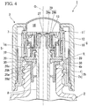
- the thickness of the crushing protrusion 20b in the vertical direction is thinner than which of the annular protrusion 20a as shown in Figs. 3 and 4 .
- the overhang recess 20c is formed so which a portion thereof is located just above the crushing protrusion 20b and the remaining portions are located just above the annular protrusion 20a as shown in Fig. 2A , and as shown in Fig. 2B which is a cross-sectional view taken along a line A- A of Fig. 2A , the overhang recess 20c is formed with a recessed amount (recessed depth) which is substantially equal to the protruding amount (protruding height) of the crushing protrusion 20b.
- Such an overhang recess 20c functions to allow the deformation of the crushing protrusion 20b or a circumferential edge portion thereof such which the deformation of the crushing protrusion 20b is not impeded, when the crushing protrusion 20b is relatively pressed against the guide cylinder 4 and crushed as described later.
- the crushing protrusion 20b is longer than the overhang recess 20c in a radially outward direction, and its width is formed to be wider in the circumferential direction.
- the inner protrusion 20d suppresses the displacement of the packing member 20 to the syringe tube 8 side caused when the crushing protrusion 20b is relatively pressed against the guide cylinder 4 as described later and the pressing force is directed in the radially inward direction of the packing member 20, by the inner circumferential surface of the inner protrusion 20d coming into contact with the outer circumferential surface of the syringe tube 8.
- the cylinder portion 10 of the movable lid portion 6 is mounted on the syringe tube 8 to freely rise, and the syringe tube 8 is connected to the lid base portion 5.
- the upper end portion of the syringe tube 8 is inserted into the movable lid portion 6 and the lid base portion 5.
- the outer diameter of the upper end portion of the syringe tube 8 gradually enlarges in a stepwise manner from the upper side toward the lower side, and a small-diameter tube portion 23, a middle-diameter tube portion 24 and a large-diameter tube portion 25 are formed in the upper end portion of the syringe tube 8.
- the small-diameter tube portion 23 is inserted into the inner circumferential wall 10b of the cylinder portion 10 to be freely vertically movable.
- a fitting groove 24a to which the annular plate portion 19b of the piston support portion 19 is fitted is circumferentially provided.
- the large-diameter tube portion 25 is fitted into the base cylinder portion 19a of the lid base portion 5, and is located just above the packing member 20.
- a ring holding groove 25a to which an O-ring 26 is fitted is circumferentially provided.
- the O-ring 26 forms an airtight seal between the large-diameter tube portion 25 and the base cylinder portion 19a.
- a valve body 27 that closes the upper end opening of the syringe tube 8 in a freely opening and closing manner is provided.
- the valve body 27 is disposed on the container axis O, and is connected to the upper end portion of the inner circumferential wall 10b of the cylinder portion 10 via bridge portions 28.
- a plurality of bridge portions 28 are disposed at intervals in the circumferential direction.
- the syringe tube 8 and the cylinder portion 10 are formed with engaging portions 29 which engage with each other when the cylinder portion 10 is located at the rising end position to the syringe tube 8.
- an outer engaging portion 29a provided in the cylinder portion 10 and an inner engaging portion 29b provided on the syringe tube 8 are provided.
- the outer engaging portion 29a annularly protrudes inward in the radial direction from the lower end of the inner circumferential wall 10b of the cylinder portion 10, and the inner engaging portion 29b annularly protrudes outward in the radial direction from the upper end of the small-diameter tube portion 23 of the syringe tube 8.
- the outer engaging portion 29a faces the inner engaging portion 29b from the lower part, and when the cylinder portion 10 rises to the syringe tube 8, the outer engaging portion 29a engages with the inner engaging portion 29b from the lower part, thereby restricting further rising movement of the cylinder portion 10.
- the urging means 7 is disposed between the cylinder portion 10 of the movable lid portion 6 and the piston portion 18 of the lid base portion 5.
- the urging means 7 is supported by the top wall portion 10c of the cylinder portion 10 from the upper part, and is supported on the bottom wall portion 18c of the piston portion 18 from the lower part.
- the urging means 7 is formed in a cylindrical shape, and is disposed coaxially with the container axis O.
- a coil spring or the like can be adopted.
- the packing member 20 is pressed against the flange portion 4b of the guide cylinder 4 in the mouth portion 2b of the container body 2. That is, the packing member 20 is sandwiched between the lid base portion 5 and the upper end opening edge of the mouth portion body 2a of the container body 2 via the flange portion 4b. At this time, when the packing member 20 is pressed against the flange portion 4b, the crushing protrusion 20b is crushed to an upper end opening edge of the mouth portion 2b.
- the packing member 20 comes into contact with the flange portion 4b without a clearance to provide a good seal between the lid base portion 5 and the flange portion 4b, i.e., between the lid base portion 5 and the upper end opening edge of the mouth portion 2b of the container body 2, thereby air-tightly closing the mouth portion 2b.
- the elastic deformation of the packing member 20 caused by crushing of the crushing protrusion 20b is allowed without impeding the elastic deformation, and the elastic deformation easily occurs.
- the movable lid portion 6 rises to a rising end position with respect to the syringe tube 8, and the engaging portions 29 (the outer engaging portions 29a, and the inner engaging portions 29b) are engaged with each other.
- the movable lid portion 6 is further raised to the container body 2, the movable lid portion 6 and the syringe tube 8 rise together via the engaging portion 29.
- the syringe tube 8 is extracted from the container body 2, and the syringe cap 3 is detached from the container body 2.
- the pressing force of the packing member 20 to the crushing protrusion 20b is released, the crushing protrusion 20b is restored and deformed into a protruding shape.
- the cylinder portion 10 is lowered against the urging force of the urging means 7, and the lid base portion 5 is also pressed downward accordingly. Then, the pressing force of lowering the lid base portion 5 acts on the packing member 20, and the crushing protrusion 20b of the packing member 20 is gradually crushed. However, until the crushing protrusion 20b is sufficiently crushed, the communication gap 30 between the packing member 20 and the flange portion 4b is ensured without being closed.
- the piston portion 18 of the lid base portion 5 slides relatively upward inside the cylinder portion 10 of the movable lid portion 6 to reduce the internal volume of the cylinder portion 10 and generate a positive pressure in the cylinder portion 10.
- the positive pressure is exerted on the interior of the container body 2 via the communication hole 13, the space 16 and the syringe tube 8.
- the positive pressure exerted on the interior of the container body 2 is released to the exterior through the communication gap 30, and the internal pressure rise in the container body 2 is suppressed.
- the lid base portion 5 presses the packing member 20 to crush the crushing protrusion 20b, and closes the communication gap 30 between the packing member 20 and the flange portion 4b.
- sealing properties between the packing member 20 and the flange portion 4b are ensured.
- the syringe container 1 of the present embodiment when the movable lid portion 6 is lowered to the lid base portion 5, the positive pressure generated in the cylinder portion 10 is released to the exterior through the communication gap 30 formed by the crushing protrusion 20b of the packing member 20, thereby making it possible to suppress an increase in internal pressure of the container body 2. Therefore, it is possible to keep the suction amount constant with high precision, regardless of the remaining amount of the contents.
- the lid base portion 5 engages with the connection 15 and rotates with the movable lid portion 6. Accordingly, when the mounting cylinder 9 is attached to or detached from the mouth portion 2b of the container body 2, it is also possible to rotate the lid base portion 5 as well as the movable lid portion 6. Accordingly, it is possible to allow the piston portion 18 to smoothly slide vertically inside the cylinder portion 10.
- the external cylinder 12 exposes the lid 11 upward, while interposing the circumferential edge portion thereof in the vertical direction between the mounting cylinder 9 and the external cylinder 12. Therefore, it is possible to firmly fix the lid 11 to the mounting cylinder 9, without impeding the pressing operation of the lid 11.
- the valve body 27 closes the upper opening of the syringe tube 8 in the initial state.
- the valve body 27 closes the upper opening of the syringe tube 8 in the initial state.
- the packing member 41 forms a locking protrusion 42 in the outer circumferential edge portion.
- the locking protrusion 42 is formed in a cylindrical shape in this embodiment, and engages with the outer circumferential surface of the upper end opening portion of the mouth portion 2b of the container body 2, i.e., the outer circumferential surface of the flange portion 4b of the guide cylinder 4 in an engageable and disengageable manner.
- the locking protrusion 42 may not be formed in a cylindrical shape, and a plurality of protruding pieces may be disposed and formed on the outer circumference at predetermined intervals.
- the packing member 41 formed with such a locking protrusion 42 By including the packing member 41 formed with such a locking protrusion 42, in the syringe container 40 of the present embodiment, after spouting the contents from the syringe tube 8, when the movable lid portion 6 is mounted to the container body 2 again, and the movable lid portion 6 is lowered, the displacement of the packing member 41 to the interior of the container body 2 caused by being crushed between the lid base portion 5 and the upper end opening edge of the mouth portion 2b of the container body 2 is suppressed by the locking protrusion 42 which engages with the outer circumferential surface (the outer circumferential surface of the flange portion 4b of the guide cylinder 4) of the upper end opening portion of the container body 2.
- the syringe container 40 of the present embodiment it is possible to satisfactorily ensure the sealing properties of the packing member 41, and it is possible to suppress the deformation and deterioration of the packing member 41 associated with the long period of use. Further, as in the first embodiment, when the movable lid portion 6 is lowered to the lid base portion 5, because the positive pressure generated in the cylinder portion 10 is released to the exterior and an internal pressure rise in the container body 2 can be suppressed, it is possible to keep the suction amount constant with high precision, regardless of the remaining amount of the contents.
- the mounting cylinder 9 may not be screwed to the mouth portion body 2a of the container body 2. That is, the present invention can be appropriately changed to another form in which the mounting cylinder 9 is mounted on the mouth portion 2b in a freely attachable and detachable manner
Landscapes
- Health & Medical Sciences (AREA)
- Engineering & Computer Science (AREA)
- Animal Behavior & Ethology (AREA)
- Public Health (AREA)
- Life Sciences & Earth Sciences (AREA)
- Veterinary Medicine (AREA)
- General Health & Medical Sciences (AREA)
- Anesthesiology (AREA)
- Vascular Medicine (AREA)
- Biomedical Technology (AREA)
- Heart & Thoracic Surgery (AREA)
- Hematology (AREA)
- Mechanical Engineering (AREA)
- Clinical Laboratory Science (AREA)
- Chemical & Material Sciences (AREA)
- Chemical Kinetics & Catalysis (AREA)
- Pharmacology & Pharmacy (AREA)
- Physics & Mathematics (AREA)
- Fluid Mechanics (AREA)
- Closures For Containers (AREA)
Claims (11)
- Contenant (1) pour seringue comprenant :un corps (2) de contenant qui renferme un contenu ;une partie de base de couvercle (5) qui est disposée sur un bord d'ouverture d'extrémité supérieure d'une partie orifice (2b) du corps (2) de contenant ;une partie couvercle mobile (6) qui est disposée pour se déplacer librement vers le haut et vers le bas par rapport à la partie de base de couvercle (5) ;un moyen de poussée (7) qui pousse la partie de base de couvercle (5) et la partie couvercle mobile (6) dans une direction de séparation verticale ; etun tube (8) de seringue qui est monté sur la partie de base de couvercle (5) et qui s'étend vers le corps (2) de contenant ;la partie orifice (2b) comprenant :un corps (2a) de partie orifice, etun cylindre de guidage (4) fixé en étant monté sur le corps (2a) de partie orifice ;la partie couvercle mobile (6) comprenant :un cylindre de montage (9), une partie inférieure (9a) qui est montée sur le corps (2a) de partie orifice d'une manière pouvant être attachée et détachée librement depuis un extérieur dans la direction radialeun couvercle (11) qui est formé pour être déformable élastiquement et qui ferme une ouverture d'extrémité supérieure du cylindre de montage (9), etune partie cylindre (10) qui est disposée à l'intérieur du cylindre de montage (9) dans une direction radiale et qui est raccordée au cylindre de montage (9) ;la partie de base de couvercle (5) comprenant une partie piston (18) qui est reliée au tube (8) de seringue et qui s'ajuste à l'intérieur de la partie cylindre (10) pour coulisser librement vers le haut et vers le bas ;la partie cylindre (10) étant montée sur le tube (8) de seringue pour se lever librement, et la partie cylindre (10) et le tube (8) de seringue étant dotés de parties de mise en prise (29) qui se mettent en prise les unes avec les autres lorsque la partie cylindre (10) est située au niveau d'une position d'extrémité se levant par rapport au tube (8) de seringue ;l'intérieur du tube (8) de seringue communiquant avec un espace entre l'ouverture d'extrémité supérieure du cylindre de montage (9) et le couvercle (11) ;la partie cylindre (10) étant dotée d'un trou de communication (13) par lequel l'intérieur et l'espace communiquent l'un avec l'autre ;dans lequel un élément de garniture (20) est disposé entre la partie de base de couvercle (5) et le bord d'ouverture d'extrémité supérieure de la partie orifice (2b) du corps (2) de contenant, etcaractérisé en ce quele cylindre de guidage (4) comprend :une partie cylindre principal cylindrique (4a) introduite dans la partie extrémité supérieure du corps (2a) de partie orifice, etune partie bride discoïde annulaire (4b) qui s'étend radialement vers l'extérieur depuis l'extrémité supérieure de la partie cylindre principal (4a) et qui se bloque avec le bord d'ouverture d'extrémité supérieure du corps (2a) de partie orifice, etune pièce d'essuyage (4c) qui dépasse radialement vers l'intérieur depuis la surface interne de la partie cylindre principal (4a) et verticalement et qui vient en contact coulissant avec la surface circonférentielle externe du tube (8) de seringue, etune saillie d'écrasement (20b) est formée sur la surface inférieure de l'élément de garniture (20), la saillie d'écrasement (20b) dépassant vers le bas et étant conçue pour appuyer contre la partie bride (4b) du cylindre de guidage (4) et pour être écrasée contre celle-ci, et un renfoncement en surplomb (20c) est formé sur la surface supérieure de l'élément de garniture (20), le renfoncement en surplomb (20c) étant au moins partiellement situé juste au-dessus de la saillie d'écrasement (20).
- Contenant (1) pour seringue selon la revendication 1, dans lequel l'élément de garniture (20) est pourvu d'une saillie de verrouillage (42) conçue pour être verrouillée avec la surface circonférentielle externe de la partie bride (4b) du cylindre de guidage (4).
- Contenant (1) pour seringue selon la revendication 1, dans lequel le cylindre de montage (9) est vissé dans le corps (2a) de partie orifice de la partie orifice (2b), et est raccordé à la partie cylindre (10) par l'intermédiaire d'un raccordement (15), et la partie de base de couvercle (5) entre en prise avec le raccordement (15) lorsque le cylindre de montage (9) tourne sur l'axe (O) du contenant, et tourne avec la partie couvercle mobile (6).
- Contenant (1) pour seringue selon la revendication 2, dans lequel le cylindre de montage (9) est vissé dans le corps (2a) de partie orifice de la partie orifice (2b), et est raccordé à la partie cylindre (10) par l'intermédiaire d'un raccordement (15), et la partie de base de couvercle (5) entre en prise avec le raccordement (15) lorsque le cylindre de montage (9) tourne sur l'axe (O) du contenant, et tourne avec la partie couvercle mobile (6).
- Contenant (1) pour seringue selon la revendication 1, dans lequel la partie couvercle mobile (6) comprend un cylindre externe (12) qui est monté sur le cylindre de montage (9) pour être immobile et non rotatif relativement verticalement depuis l'extérieur dans la direction radiale, et le cylindre externe (12) fait apparaître le couvercle (11) vers le haut, tout en interposant une partie marginale circonférentielle du couvercle (11) dans la direction verticale entre le cylindre de montage (9) et le cylindre externe (12).
- Contenant (1) pour seringue selon la revendication 2, dans lequel la partie couvercle mobile (6) comprend un cylindre externe (12) qui est monté sur le cylindre de montage (9) pour être immobile et non rotatif relativement verticalement depuis l'extérieur dans la direction radiale, et le cylindre externe (12) fait apparaître le couvercle (11) vers le haut, tout en interposant une partie marginale circonférentielle du couvercle (11) dans la direction verticale entre le cylindre de montage (9) et le cylindre externe (12).
- Contenant (1) de seringue selon la revendication 3, dans lequel la partie couvercle mobile (6) comprend un cylindre externe (12) qui est monté sur le cylindre de montage (9) pour être immobile et non rotatif relativement verticalement depuis l'extérieur dans la direction radiale, et le cylindre externe (12) fait apparaître le couvercle (11) vers le haut, tout en interposant une partie marginale circonférentielle du couvercle (11) dans la direction verticale entre le cylindre de montage (9) et le cylindre externe (12).
- Contenant (1) pour seringue selon la revendication 4, dans lequel la partie couvercle mobile (6) comprend un cylindre externe (12) qui est monté sur le cylindre de montage (9) pour être immobile et non rotatif relativement verticalement depuis l'extérieur dans la direction radiale, et le cylindre externe (12) fait apparaître le couvercle (11) vers le haut, tout en interposant une partie marginale circonférentielle du couvercle (11) dans la direction verticale entre le cylindre de montage (9) et le cylindre externe (12).
- Contenant (1) pour seringue selon la revendication 1, dans lequel l'élément de garniture (20) est un élément de garniture annulaire, et la saillie d'écrasement (20b) est une pluralité de saillies d'écrasement (20b) qui sont formées sur une partie marginale circonférentielle interne de l'élément de garniture annulaire à intervalles égaux dans une direction circonférentielle.
- Contenant (1) pour seringue selon la revendication 1, dans lequel l'élément de garniture (20) est un élément de garniture annulaire, et la saillie d'écrasement (20b) est formée pour être plus longue que le renfoncement en surplomb (20c) vers l'extérieur dans la direction radiale et pour être plus large dans une direction circonférentielle.
- Contenant (1) pour seringue selon la revendication 1, dans lequel une quantité en creux du renfoncement en surplomb (20c) est sensiblement égale à la quantité saillante de la saillie d'écrasement (20b).
Applications Claiming Priority (2)
| Application Number | Priority Date | Filing Date | Title |
|---|---|---|---|
| JP2014223599A JP6379011B2 (ja) | 2014-10-31 | 2014-10-31 | スポイト容器 |
| PCT/JP2015/072406 WO2016067705A1 (fr) | 2014-10-31 | 2015-08-06 | Récipient pour seringues |
Publications (3)
| Publication Number | Publication Date |
|---|---|
| EP3214014A1 EP3214014A1 (fr) | 2017-09-06 |
| EP3214014A4 EP3214014A4 (fr) | 2018-06-13 |
| EP3214014B1 true EP3214014B1 (fr) | 2019-12-04 |
Family
ID=55857052
Family Applications (1)
| Application Number | Title | Priority Date | Filing Date |
|---|---|---|---|
| EP15854713.3A Active EP3214014B1 (fr) | 2014-10-31 | 2015-08-06 | Récipient pour seringues |
Country Status (6)
| Country | Link |
|---|---|
| US (1) | US10143623B2 (fr) |
| EP (1) | EP3214014B1 (fr) |
| JP (1) | JP6379011B2 (fr) |
| KR (1) | KR102271121B1 (fr) |
| CN (1) | CN106794928B (fr) |
| WO (1) | WO2016067705A1 (fr) |
Families Citing this family (6)
| Publication number | Priority date | Publication date | Assignee | Title |
|---|---|---|---|---|
| JP6917940B2 (ja) * | 2018-03-29 | 2021-08-11 | 太平洋工業株式会社 | バルブキャップ及びキャップ付きバルブ |
| CN114341014B (zh) * | 2019-09-02 | 2024-12-03 | 宝洁公司 | 用于粘性产品的分配器 |
| JP7313248B2 (ja) * | 2019-09-30 | 2023-07-24 | 株式会社吉野工業所 | スポイト容器 |
| CN110934410B (zh) * | 2019-11-29 | 2022-06-14 | 上海容奥包装科技有限公司 | 一种睫毛膏装置 |
| JP7382911B2 (ja) * | 2020-07-31 | 2023-11-17 | 株式会社吉野工業所 | スポイト容器 |
| WO2023004577A1 (fr) * | 2021-07-27 | 2023-02-02 | The Procter & Gamble Company | Distributeur pour produits visqueux |
Family Cites Families (11)
| Publication number | Priority date | Publication date | Assignee | Title |
|---|---|---|---|---|
| JPH0642735Y2 (ja) | 1989-03-17 | 1994-11-09 | 株式会社吉野工業所 | スポイト付き容器 |
| JPH0752056Y2 (ja) * | 1989-04-06 | 1995-11-29 | 釜屋化学工業株式会社 | スポイト付き容器 |
| JPH0642735A (ja) | 1992-07-24 | 1994-02-18 | Mitsubishi Heavy Ind Ltd | ガスタービンコンバインド設備 |
| JP3291531B2 (ja) * | 1993-07-02 | 2002-06-10 | 三洋化学工業株式会社 | キャップの中栓 |
| JPH0717757U (ja) * | 1993-08-31 | 1995-03-31 | 株式会社吉野工業所 | スポイト付き容器 |
| JP2549350Y2 (ja) * | 1993-10-15 | 1997-09-30 | 鐘紡株式会社 | スポイト容器 |
| JP3387649B2 (ja) * | 1994-09-16 | 2003-03-17 | 富士写真フイルム株式会社 | 点着チップ |
| JP4251340B2 (ja) * | 1998-09-25 | 2009-04-08 | 株式会社資生堂 | スポイト付きキャップ |
| US8403008B2 (en) | 2010-05-24 | 2013-03-26 | Elc Management, Llc | Metered dose applicator with light for activating product |
| CN103025622B (zh) | 2010-06-07 | 2015-07-29 | 莱雅公司 | 使用吸液管的封装及涂抹装置 |
| KR200453126Y1 (ko) | 2010-07-23 | 2011-04-13 | 주식회사 에프에스코리아 | 스포이드형 화장품 용기 |
-
2014
- 2014-10-31 JP JP2014223599A patent/JP6379011B2/ja active Active
-
2015
- 2015-08-06 EP EP15854713.3A patent/EP3214014B1/fr active Active
- 2015-08-06 WO PCT/JP2015/072406 patent/WO2016067705A1/fr not_active Ceased
- 2015-08-06 KR KR1020177004361A patent/KR102271121B1/ko active Active
- 2015-08-06 CN CN201580046182.9A patent/CN106794928B/zh active Active
- 2015-08-06 US US15/328,826 patent/US10143623B2/en active Active
Non-Patent Citations (1)
| Title |
|---|
| None * |
Also Published As
| Publication number | Publication date |
|---|---|
| WO2016067705A1 (fr) | 2016-05-06 |
| JP6379011B2 (ja) | 2018-08-22 |
| EP3214014A4 (fr) | 2018-06-13 |
| JP2016088556A (ja) | 2016-05-23 |
| US10143623B2 (en) | 2018-12-04 |
| CN106794928B (zh) | 2018-08-24 |
| KR102271121B1 (ko) | 2021-07-01 |
| EP3214014A1 (fr) | 2017-09-06 |
| KR20170078588A (ko) | 2017-07-07 |
| CN106794928A (zh) | 2017-05-31 |
| US20170216141A1 (en) | 2017-08-03 |
Similar Documents
| Publication | Publication Date | Title |
|---|---|---|
| EP3214014B1 (fr) | Récipient pour seringues | |
| EP3480130B1 (fr) | Récipient de décharge | |
| AU2015259182A1 (en) | Mechanically sealed container cap | |
| JP6335756B2 (ja) | スポイト容器 | |
| JP7158253B2 (ja) | 吐出器 | |
| JP7486456B2 (ja) | スポイト容器 | |
| CN106163940B (zh) | 带吸管的容器 | |
| JP7250492B2 (ja) | 混合容器 | |
| JP6298753B2 (ja) | スポイト容器 | |
| JP7399016B2 (ja) | スポイト容器 | |
| JP5311475B2 (ja) | 液体吐出ポンプ | |
| JP7321616B1 (ja) | 蓋付き容器および蓋ユニット | |
| JP2016222291A (ja) | スポイト容器 | |
| JP2019064673A (ja) | 吐出器 | |
| JP2019177940A (ja) | ポンプ機構及び吐出器 | |
| JP2024041402A (ja) | スポイト容器 | |
| JP6007019B2 (ja) | 吐出容器 | |
| WO2024135776A1 (fr) | Récipient compte-gouttes | |
| JP2024089218A (ja) | スポイト容器 | |
| JP2024089211A (ja) | スポイト容器 | |
| JP2024156405A (ja) | スポイト容器 | |
| JP2016113195A (ja) | 噴出容器 | |
| JP2014213172A (ja) | 吐出容器 | |
| JP2021035841A (ja) | 吐出器 |
Legal Events
| Date | Code | Title | Description |
|---|---|---|---|
| STAA | Information on the status of an ep patent application or granted ep patent |
Free format text: STATUS: THE INTERNATIONAL PUBLICATION HAS BEEN MADE |
|
| PUAI | Public reference made under article 153(3) epc to a published international application that has entered the european phase |
Free format text: ORIGINAL CODE: 0009012 |
|
| STAA | Information on the status of an ep patent application or granted ep patent |
Free format text: STATUS: REQUEST FOR EXAMINATION WAS MADE |
|
| 17P | Request for examination filed |
Effective date: 20170531 |
|
| AK | Designated contracting states |
Kind code of ref document: A1 Designated state(s): AL AT BE BG CH CY CZ DE DK EE ES FI FR GB GR HR HU IE IS IT LI LT LU LV MC MK MT NL NO PL PT RO RS SE SI SK SM TR |
|
| AX | Request for extension of the european patent |
Extension state: BA ME |
|
| DAV | Request for validation of the european patent (deleted) | ||
| DAX | Request for extension of the european patent (deleted) | ||
| A4 | Supplementary search report drawn up and despatched |
Effective date: 20180511 |
|
| RIC1 | Information provided on ipc code assigned before grant |
Ipc: B01L 3/02 20060101ALI20180504BHEP Ipc: A61J 1/20 20060101ALI20180504BHEP Ipc: B65D 53/02 20060101ALI20180504BHEP Ipc: B65D 51/32 20060101AFI20180504BHEP |
|
| STAA | Information on the status of an ep patent application or granted ep patent |
Free format text: STATUS: EXAMINATION IS IN PROGRESS |
|
| 17Q | First examination report despatched |
Effective date: 20190131 |
|
| GRAP | Despatch of communication of intention to grant a patent |
Free format text: ORIGINAL CODE: EPIDOSNIGR1 |
|
| STAA | Information on the status of an ep patent application or granted ep patent |
Free format text: STATUS: GRANT OF PATENT IS INTENDED |
|
| INTG | Intention to grant announced |
Effective date: 20190826 |
|
| GRAS | Grant fee paid |
Free format text: ORIGINAL CODE: EPIDOSNIGR3 |
|
| GRAA | (expected) grant |
Free format text: ORIGINAL CODE: 0009210 |
|
| STAA | Information on the status of an ep patent application or granted ep patent |
Free format text: STATUS: THE PATENT HAS BEEN GRANTED |
|
| AK | Designated contracting states |
Kind code of ref document: B1 Designated state(s): AL AT BE BG CH CY CZ DE DK EE ES FI FR GB GR HR HU IE IS IT LI LT LU LV MC MK MT NL NO PL PT RO RS SE SI SK SM TR |
|
| REG | Reference to a national code |
Ref country code: GB Ref legal event code: FG4D |
|
| REG | Reference to a national code |
Ref country code: CH Ref legal event code: EP |
|
| REG | Reference to a national code |
Ref country code: AT Ref legal event code: REF Ref document number: 1209117 Country of ref document: AT Kind code of ref document: T Effective date: 20191215 |
|
| REG | Reference to a national code |
Ref country code: DE Ref legal event code: R096 Ref document number: 602015043208 Country of ref document: DE |
|
| REG | Reference to a national code |
Ref country code: IE Ref legal event code: FG4D |
|
| REG | Reference to a national code |
Ref country code: NL Ref legal event code: MP Effective date: 20191204 |
|
| REG | Reference to a national code |
Ref country code: LT Ref legal event code: MG4D |
|
| PG25 | Lapsed in a contracting state [announced via postgrant information from national office to epo] |
Ref country code: SE Free format text: LAPSE BECAUSE OF FAILURE TO SUBMIT A TRANSLATION OF THE DESCRIPTION OR TO PAY THE FEE WITHIN THE PRESCRIBED TIME-LIMIT Effective date: 20191204 Ref country code: LV Free format text: LAPSE BECAUSE OF FAILURE TO SUBMIT A TRANSLATION OF THE DESCRIPTION OR TO PAY THE FEE WITHIN THE PRESCRIBED TIME-LIMIT Effective date: 20191204 Ref country code: FI Free format text: LAPSE BECAUSE OF FAILURE TO SUBMIT A TRANSLATION OF THE DESCRIPTION OR TO PAY THE FEE WITHIN THE PRESCRIBED TIME-LIMIT Effective date: 20191204 Ref country code: BG Free format text: LAPSE BECAUSE OF FAILURE TO SUBMIT A TRANSLATION OF THE DESCRIPTION OR TO PAY THE FEE WITHIN THE PRESCRIBED TIME-LIMIT Effective date: 20200304 Ref country code: GR Free format text: LAPSE BECAUSE OF FAILURE TO SUBMIT A TRANSLATION OF THE DESCRIPTION OR TO PAY THE FEE WITHIN THE PRESCRIBED TIME-LIMIT Effective date: 20200305 Ref country code: NO Free format text: LAPSE BECAUSE OF FAILURE TO SUBMIT A TRANSLATION OF THE DESCRIPTION OR TO PAY THE FEE WITHIN THE PRESCRIBED TIME-LIMIT Effective date: 20200304 Ref country code: LT Free format text: LAPSE BECAUSE OF FAILURE TO SUBMIT A TRANSLATION OF THE DESCRIPTION OR TO PAY THE FEE WITHIN THE PRESCRIBED TIME-LIMIT Effective date: 20191204 |
|
| PG25 | Lapsed in a contracting state [announced via postgrant information from national office to epo] |
Ref country code: HR Free format text: LAPSE BECAUSE OF FAILURE TO SUBMIT A TRANSLATION OF THE DESCRIPTION OR TO PAY THE FEE WITHIN THE PRESCRIBED TIME-LIMIT Effective date: 20191204 Ref country code: RS Free format text: LAPSE BECAUSE OF FAILURE TO SUBMIT A TRANSLATION OF THE DESCRIPTION OR TO PAY THE FEE WITHIN THE PRESCRIBED TIME-LIMIT Effective date: 20191204 |
|
| PG25 | Lapsed in a contracting state [announced via postgrant information from national office to epo] |
Ref country code: AL Free format text: LAPSE BECAUSE OF FAILURE TO SUBMIT A TRANSLATION OF THE DESCRIPTION OR TO PAY THE FEE WITHIN THE PRESCRIBED TIME-LIMIT Effective date: 20191204 |
|
| PG25 | Lapsed in a contracting state [announced via postgrant information from national office to epo] |
Ref country code: EE Free format text: LAPSE BECAUSE OF FAILURE TO SUBMIT A TRANSLATION OF THE DESCRIPTION OR TO PAY THE FEE WITHIN THE PRESCRIBED TIME-LIMIT Effective date: 20191204 Ref country code: CZ Free format text: LAPSE BECAUSE OF FAILURE TO SUBMIT A TRANSLATION OF THE DESCRIPTION OR TO PAY THE FEE WITHIN THE PRESCRIBED TIME-LIMIT Effective date: 20191204 Ref country code: NL Free format text: LAPSE BECAUSE OF FAILURE TO SUBMIT A TRANSLATION OF THE DESCRIPTION OR TO PAY THE FEE WITHIN THE PRESCRIBED TIME-LIMIT Effective date: 20191204 Ref country code: RO Free format text: LAPSE BECAUSE OF FAILURE TO SUBMIT A TRANSLATION OF THE DESCRIPTION OR TO PAY THE FEE WITHIN THE PRESCRIBED TIME-LIMIT Effective date: 20191204 Ref country code: ES Free format text: LAPSE BECAUSE OF FAILURE TO SUBMIT A TRANSLATION OF THE DESCRIPTION OR TO PAY THE FEE WITHIN THE PRESCRIBED TIME-LIMIT Effective date: 20191204 Ref country code: PT Free format text: LAPSE BECAUSE OF FAILURE TO SUBMIT A TRANSLATION OF THE DESCRIPTION OR TO PAY THE FEE WITHIN THE PRESCRIBED TIME-LIMIT Effective date: 20200429 |
|
| PG25 | Lapsed in a contracting state [announced via postgrant information from national office to epo] |
Ref country code: SM Free format text: LAPSE BECAUSE OF FAILURE TO SUBMIT A TRANSLATION OF THE DESCRIPTION OR TO PAY THE FEE WITHIN THE PRESCRIBED TIME-LIMIT Effective date: 20191204 Ref country code: IS Free format text: LAPSE BECAUSE OF FAILURE TO SUBMIT A TRANSLATION OF THE DESCRIPTION OR TO PAY THE FEE WITHIN THE PRESCRIBED TIME-LIMIT Effective date: 20200404 Ref country code: SK Free format text: LAPSE BECAUSE OF FAILURE TO SUBMIT A TRANSLATION OF THE DESCRIPTION OR TO PAY THE FEE WITHIN THE PRESCRIBED TIME-LIMIT Effective date: 20191204 |
|
| REG | Reference to a national code |
Ref country code: DE Ref legal event code: R097 Ref document number: 602015043208 Country of ref document: DE |
|
| REG | Reference to a national code |
Ref country code: AT Ref legal event code: MK05 Ref document number: 1209117 Country of ref document: AT Kind code of ref document: T Effective date: 20191204 |
|
| PLBE | No opposition filed within time limit |
Free format text: ORIGINAL CODE: 0009261 |
|
| STAA | Information on the status of an ep patent application or granted ep patent |
Free format text: STATUS: NO OPPOSITION FILED WITHIN TIME LIMIT |
|
| PG25 | Lapsed in a contracting state [announced via postgrant information from national office to epo] |
Ref country code: DK Free format text: LAPSE BECAUSE OF FAILURE TO SUBMIT A TRANSLATION OF THE DESCRIPTION OR TO PAY THE FEE WITHIN THE PRESCRIBED TIME-LIMIT Effective date: 20191204 |
|
| 26N | No opposition filed |
Effective date: 20200907 |
|
| PG25 | Lapsed in a contracting state [announced via postgrant information from national office to epo] |
Ref country code: SI Free format text: LAPSE BECAUSE OF FAILURE TO SUBMIT A TRANSLATION OF THE DESCRIPTION OR TO PAY THE FEE WITHIN THE PRESCRIBED TIME-LIMIT Effective date: 20191204 Ref country code: AT Free format text: LAPSE BECAUSE OF FAILURE TO SUBMIT A TRANSLATION OF THE DESCRIPTION OR TO PAY THE FEE WITHIN THE PRESCRIBED TIME-LIMIT Effective date: 20191204 Ref country code: PL Free format text: LAPSE BECAUSE OF FAILURE TO SUBMIT A TRANSLATION OF THE DESCRIPTION OR TO PAY THE FEE WITHIN THE PRESCRIBED TIME-LIMIT Effective date: 20191204 |
|
| PG25 | Lapsed in a contracting state [announced via postgrant information from national office to epo] |
Ref country code: IT Free format text: LAPSE BECAUSE OF FAILURE TO SUBMIT A TRANSLATION OF THE DESCRIPTION OR TO PAY THE FEE WITHIN THE PRESCRIBED TIME-LIMIT Effective date: 20191204 |
|
| PG25 | Lapsed in a contracting state [announced via postgrant information from national office to epo] |
Ref country code: MC Free format text: LAPSE BECAUSE OF FAILURE TO SUBMIT A TRANSLATION OF THE DESCRIPTION OR TO PAY THE FEE WITHIN THE PRESCRIBED TIME-LIMIT Effective date: 20191204 |
|
| REG | Reference to a national code |
Ref country code: CH Ref legal event code: PL |
|
| PG25 | Lapsed in a contracting state [announced via postgrant information from national office to epo] |
Ref country code: LI Free format text: LAPSE BECAUSE OF NON-PAYMENT OF DUE FEES Effective date: 20200831 Ref country code: LU Free format text: LAPSE BECAUSE OF NON-PAYMENT OF DUE FEES Effective date: 20200806 Ref country code: CH Free format text: LAPSE BECAUSE OF NON-PAYMENT OF DUE FEES Effective date: 20200831 |
|
| REG | Reference to a national code |
Ref country code: BE Ref legal event code: MM Effective date: 20200831 |
|
| PG25 | Lapsed in a contracting state [announced via postgrant information from national office to epo] |
Ref country code: IE Free format text: LAPSE BECAUSE OF NON-PAYMENT OF DUE FEES Effective date: 20200806 Ref country code: BE Free format text: LAPSE BECAUSE OF NON-PAYMENT OF DUE FEES Effective date: 20200831 |
|
| PG25 | Lapsed in a contracting state [announced via postgrant information from national office to epo] |
Ref country code: TR Free format text: LAPSE BECAUSE OF FAILURE TO SUBMIT A TRANSLATION OF THE DESCRIPTION OR TO PAY THE FEE WITHIN THE PRESCRIBED TIME-LIMIT Effective date: 20191204 Ref country code: MT Free format text: LAPSE BECAUSE OF FAILURE TO SUBMIT A TRANSLATION OF THE DESCRIPTION OR TO PAY THE FEE WITHIN THE PRESCRIBED TIME-LIMIT Effective date: 20191204 Ref country code: CY Free format text: LAPSE BECAUSE OF FAILURE TO SUBMIT A TRANSLATION OF THE DESCRIPTION OR TO PAY THE FEE WITHIN THE PRESCRIBED TIME-LIMIT Effective date: 20191204 |
|
| PG25 | Lapsed in a contracting state [announced via postgrant information from national office to epo] |
Ref country code: MK Free format text: LAPSE BECAUSE OF FAILURE TO SUBMIT A TRANSLATION OF THE DESCRIPTION OR TO PAY THE FEE WITHIN THE PRESCRIBED TIME-LIMIT Effective date: 20191204 |
|
| PGFP | Annual fee paid to national office [announced via postgrant information from national office to epo] |
Ref country code: DE Payment date: 20250702 Year of fee payment: 11 |
|
| PGFP | Annual fee paid to national office [announced via postgrant information from national office to epo] |
Ref country code: GB Payment date: 20250703 Year of fee payment: 11 |
|
| PGFP | Annual fee paid to national office [announced via postgrant information from national office to epo] |
Ref country code: FR Payment date: 20250703 Year of fee payment: 11 |