EP3214236B1 - Verfahren zur herstellung einer paneelstruktur für eine externe seitenwand oder eine verkleidung eines gebäudes sowie gebäude mit solch einer paneelstruktur - Google Patents
Verfahren zur herstellung einer paneelstruktur für eine externe seitenwand oder eine verkleidung eines gebäudes sowie gebäude mit solch einer paneelstruktur Download PDFInfo
- Publication number
- EP3214236B1 EP3214236B1 EP17159271.0A EP17159271A EP3214236B1 EP 3214236 B1 EP3214236 B1 EP 3214236B1 EP 17159271 A EP17159271 A EP 17159271A EP 3214236 B1 EP3214236 B1 EP 3214236B1
- Authority
- EP
- European Patent Office
- Prior art keywords
- seal
- longitudinal
- building
- base portions
- strip portion
- Prior art date
- Legal status (The legal status is an assumption and is not a legal conclusion. Google has not performed a legal analysis and makes no representation as to the accuracy of the status listed.)
- Active
Links
Images


Classifications
-
- E—FIXED CONSTRUCTIONS
- E04—BUILDING
- E04B—GENERAL BUILDING CONSTRUCTIONS; WALLS, e.g. PARTITIONS; ROOFS; FLOORS; CEILINGS; INSULATION OR OTHER PROTECTION OF BUILDINGS
- E04B2/00—Walls, e.g. partitions, for buildings; Wall construction with regard to insulation; Connections specially adapted to walls
- E04B2/88—Curtain walls
- E04B2/96—Curtain walls comprising panels attached to the structure through mullions or transoms
-
- E—FIXED CONSTRUCTIONS
- E04—BUILDING
- E04B—GENERAL BUILDING CONSTRUCTIONS; WALLS, e.g. PARTITIONS; ROOFS; FLOORS; CEILINGS; INSULATION OR OTHER PROTECTION OF BUILDINGS
- E04B2/00—Walls, e.g. partitions, for buildings; Wall construction with regard to insulation; Connections specially adapted to walls
- E04B2/72—Non-load-bearing walls of elements of relatively thin form with respect to the thickness of the wall
- E04B2/721—Non-load-bearing walls of elements of relatively thin form with respect to the thickness of the wall connections specially adapted therefor
-
- E—FIXED CONSTRUCTIONS
- E06—DOORS, WINDOWS, SHUTTERS, OR ROLLER BLINDS IN GENERAL; LADDERS
- E06B—FIXED OR MOVABLE CLOSURES FOR OPENINGS IN BUILDINGS, VEHICLES, FENCES OR LIKE ENCLOSURES IN GENERAL, e.g. DOORS, WINDOWS, BLINDS, GATES
- E06B3/00—Window sashes, door leaves, or like elements for closing wall or like openings; Layout of fixed or moving closures, e.g. windows in wall or like openings; Features of rigidly-mounted outer frames relating to the mounting of wing frames
- E06B3/04—Wing frames not characterised by the manner of movement
- E06B3/06—Single frames
-
- E—FIXED CONSTRUCTIONS
- E06—DOORS, WINDOWS, SHUTTERS, OR ROLLER BLINDS IN GENERAL; LADDERS
- E06B—FIXED OR MOVABLE CLOSURES FOR OPENINGS IN BUILDINGS, VEHICLES, FENCES OR LIKE ENCLOSURES IN GENERAL, e.g. DOORS, WINDOWS, BLINDS, GATES
- E06B7/00—Special arrangements or measures in connection with doors or windows
- E06B7/14—Measures for draining-off condensed water or water leaking-in frame members for draining off condensation water, throats at the bottom of a sash
Definitions
- the present invention concerns a method for making a panel structure for an external side wall or a covering of a building.
- panel structures having a row of section elements and a series of panels or sheets which are coupled to said section elements and, for example, are defined by transparent or semi-transparent modules.
- the panels are abutted side by side to one another so as to define a continuous facade or covering.
- the water tends to run unpredictably in the section elements in a longitudinal direction, and drops both outside and inside the building, at the junction zones between the section elements. Therefore, as time passes, the water that has seeped into the building tends to damage the internal walls and forms undesired dark marks below the junction zones between the sections.
- silicone or a similar sealant is applied at the junction zones between the section elements, during assembly of the latter, to obtain a seal in said zones.
- a connecting plate is fitted at each junction zone, so as to define a sort of patch that prevents the water from leaking out, favouring longitudinal flow and consequent drainage to the outside.
- the section elements are fixed to the wall by means of additional brackets, to prevent the water penetrating into the wall through the holes of the fastening system.
- the brackets are fixed to the section elements by means of horizontal holes and screws, which are higher than the area where the water tends to accumulate and, therefore, do not create outlet points from which the water could infiltrate the wall.
- This type of fastening is complex and costly to install; therefore, it is preferable to find a simpler alternative that prevents the water from infiltrating the wall.
- US2005138889A1 discloses a curtain wall including a sill member, which is formed as an integral aluminum extrusion and is secured by fasteners to a concrete slab of a building.
- a head member similar to the sill member, secures the curtain wall to a concrete slab provided between floors of the building.
- Vertical mullions are secured between the sill member and the head member at appropriate intervals along the curtain wall.
- a support member is disposed on a base of the sill member, and a setting block is disposed on such support member.
- Multiple panel members are arranged side-by-side, are secured between the sill member and the head member and are sealed by gaskets and/or structural silicon.
- US2016053529 discloses a window unit that is placed on a bottom sub-sill unit, for improved drainage of water, beading through drain holes into a channel. Water exits from such channel through holes formed at a bottom corner of the bottom sub-sill unit. In addition, an inclined lip directs the drained water away.
- the object of the present invention is to provide a method for making a panel structure for an external side wall or a covering of a building, which solves the above drawbacks in a simple inexpensive manner.
- a method for making a panel structure for an external side wall or a covering of a building, as defined in claim 1.
- the present invention further relates to a building according to claim 9.
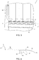
- the reference number 1 indicates, overall, an external side wall of a building (partially illustrated).
- the wall 1 is vertical, but could also have an inclination with respect to the vertical.
- the wall 1 comprises a wall 2 and a panel structure 3 which, in particular, engages and closes an opening, defined at the bottom by a horizontal surface 5 of the wall 2.
- the structure 3 comprises a row of section elements 6, which rest on the surface 5 and are aligned with one another along a longitudinal axis 7.
- Each of the section elements 6 consists of a set of pieces, which are fixed with respect to one another, are preferably made of aluminium or an aluminium alloy and are obtained by means of extrusion.
- the section elements 6 can be made of different materials, for example plastic (PVC, polyester, etc%) or sheet metal, and/or they can be obtained by means of different processes, for example by moulding or by cold or hot bending.
- the cross section orthogonal to the axis 7, is the same for all the section elements 6 and is constant along the axis 7, if we exclude the presence of drainage holes 10 spaced longitudinally from one another.
- Said cross section is essentially defined by a U shape, so that each section element 6 comprises a base portion 11, an external wall 12 and an internal wall 13.
- the walls 12 and 13 project upwards from opposite longitudinal edges of the portion 11 and horizontally face each other. Therefore, the walls 12, 13 and the portion 11 define a seat 14, which is open at the top and at the longitudinal ends of the section element 6.
- the holes 10 are made on the external wall 12 at the lower end of the seat 14.
- the walls constituting the portion 11 can be provided with drainage holes longitudinally spaced from one another.
- the structure 3 further comprises a plurality of fastening members 16, which fix the section elements 6 to the wall 2.
- each fastening member 16 comprises a plug 17 inserted in the wall 2 and a screw 18 which engages a corresponding hole in the portion 11 and is screwed into the plug 17 so as to secure the portion 11 against the surface 5.
- Figure 3 shows that the section element 6 preferably comprises a drip profile 19 (partially illustrated) to ensure that the drained water, coming out of the holes 10, runs well away from the external face of the wall 2; and/or a gutter (not illustrated) to collect the drained water.
- a drip profile 19 partially illustrated
- a gutter not illustrated
- the gutter and/or the drip profile 19 project outwards from the external wall 12 (not illustrated in figure 3 ), starting from a position below the holes 10, so as to prevent the drained water from dropping directly onto the wall 2.
- the gutter and/or the drip profile 19 comprise a longitudinal end edge which is vertically blocked between the portion 11 and the surface 5, in a manner not illustrated in detail.
- the structure 3 further comprises a plurality of panels 21, which are vertical and coplanar with one another, are abutted to one another along the axis 7 so as to form a continuous panelling and have respective bottom end portions 22 which engage the channel 15 substantially without play in a horizontal direction orthogonal to the axis 7.
- Spacer elements or sealing elements 23 can be arranged between the panels 21 and the walls 12,13.
- the panels 21 have the same standard dimensions.
- the panels 21 are defined by respective plates or modules made of polycarbonate, which are transparent or semi-transparent so as to define a window of the building.
- the structure 3 further comprises a seal 24, which is made of flexible material, for example polyethylene, and comprises a strip portion 25 which is continuous along the axis 7 and engages the seats 14 so as to cover the junction zones between the portions 11.
- the strip portion 25 has a length greater than that of a single seat 14, so as to be used to cover at least two consecutive junction zones.
- the strip portion 25 engages the whole channel 15: in this way, it is possible to store the seal 24 in the form of a coil, unwind said coil during assembly of the structure 3 so as to arrange the seal 24 directly inside the channel 15 and then cut the seal 24 to the desired length.
- the strip portion 25 has a top face 26, vertically facing the portions 22, and a bottom face 27 vertically facing the portion 11.
- the portions 22 are delimited at the bottom by a surface 28 ( fig. 1 and 2 ) which vertically overlaps the face 26, so that it is entirely covered by the face 26. In this way, any water that runs along the portions 22 does not drop directly onto the portions 11 but drops onto the strip portion 25 that guides the water towards the holes 10 and prevents the water passing through the junction zones between adjacent portions 11.
- the strip portion 25 has a longitudinal edge 29 which, in a horizontal direction orthogonal to the axis 7, is spaced from the external wall 12, so that there is an empty space or gap 30 ( fig. 1 ) allowing the water to drop from the edge 29 onto the portion 11 in the vicinity of the holes 10.
- the strip portion 25 terminates in a tongue 31, which is not covered by the portions 22 and rests against the walls 13. In this way, by dripping onto the tongue 31, the water does not go directly onto the portion 11 but is guided towards the holes 10.
- the tongue 31 is folded upwards with respect to the remaining part of the strip portion 25, i.e. it forms a fold which is arranged at a longitudinal edge of the portions 22.
- the seal 24 further comprises at least one appendage 32 which projects from the face 27 and is coupled to a corresponding vertical tongue 33 ( fig. 1 ) forming part of the portion 11.
- the coupling between the tongue 33 and the appendage 32 defines a reference for correctly positioning the seal 24 in the channel 15, in a horizontal direction orthogonal to the axis 7, during assembly.
- the appendage 32 defines a retaining seat 34 which is open at the bottom and is engaged by the tongue 33.
- the appendage 32 and therefore the retaining seat 34 are continuous along the axis 7, hence the seal 24 can be produced by extrusion.
- the faces 27 and 26 rest against the portions 11 and 22 respectively, therefore the strip portion 25 remains vertically clamped between the panels 21 and the section elements 6.
- a plurality of longitudinal and parallel ribs are provided on the face 26, in order to maintain the panels 21 slightly raised with respect to the face 26. This allows the condensate accumulated on the cells of the panels 21 to flow out and down the face 26, allowing said cell to breathe.
- the longitudinal ends of the structure 3 are defined by respective uprights 37, only one of which is illustrated.
- the seal 24 has two ends 38 which are opposite each other and are folded upwards with respect to the remaining horizontal part, so that they are arranged between the panels 21 and the uprights 37. In this way, the portion 38 forces the water that has accumulated in the section elements 6 to exit solely through the drainage holes 10, preventing an exit at the end of the structure 3 in the junction zone between the uprights 37 and the channel 15.
- Figures 5 to 8 show respective variations, the component parts of which are indicated, where possible, by the same reference numbers as those used in figure 1 . Said variations indicate that the cross section of the section elements 6 and/or the shape of the strip portion 25 after insertion in the channel 15 may be different from what is shown in figure 1 .
- the seal 24 could be defined solely by the strip portion 25, without any appendage 32.
- the strip portion 25 is arranged in the channel 15 so as to form a U shape, i.e. so that it too takes on a channel or gutter configuration to collect the water.
- the structure 3 can be used in a covering of a building (for example a horizontal covering) and not for the wall 1 described above.
- the panels 21 comprise respective flat sheets 21a, while the portions 22 are defined by appendages that project downwards from the ends of the sheets 21a and, preferably, have a shape and size such as to be snap-hooked into the top openings of the seats 14.
- section elements 6 can be fixed to a support defined by a building structure different from the wall 2, for example to a horizontal beam.
- the section elements 6, the fastening members 16, the panels 21 and the seal 24 define part of a kit which can be supplied to building firms for installing the structure 3.
- one single seal 24 is provided in common with at least some of the section elements, so as to simplify production and installation of the seal 24.
- the seal 24 can be installed after fastening the section elements 6 and forming the channel 15, unwinding said seal 24 from a coil, in a relatively quick manner, and inserting it manually into the seats 14 on the bottom of the channel 15.
- the strip portion 25 adapts to the cross section of the channel 15, since it is made of flexible material.
- the positioning of the seal 24 is relatively simple, quick and accurate, due to the flexibility of the material and possible presence of the appendage 32.
- the strip portion 25 covers all the screws 18, and not only the junction zones between the portions 11, so that the plugs 17 are protected from any infiltration of water.
- This solution consequently avoids different fastening systems, which in other known solutions are provided on the outside of the section elements 6, are generally more complex and can compromise the aesthetics of the structure 3.
- cross section and/or the material of the section elements 6 and/or of the seal 24 may be different from the description provided by way of example.
Landscapes
- Engineering & Computer Science (AREA)
- Civil Engineering (AREA)
- Structural Engineering (AREA)
- Architecture (AREA)
- Physics & Mathematics (AREA)
- Electromagnetism (AREA)
- Building Environments (AREA)
- Panels For Use In Building Construction (AREA)
Claims (15)
- Verfahren zur Herstellung einer Paneelstruktur (3) für eine äußere Seitenwand oder eine Abdeckung eines Gebäudes (1) durch einen Bausatz, der Folgendes umfasst:- eine Vielzahl von Abschnittselementen (6), die sich entlang einer longitudinalen Achse (7) erstrecken und entsprechende Basisteile (11) mit entsprechenden Sitzen (14) umfassen, die an der Oberseite und an ihren longitudinalen Enden offen sind;- Befestigungsmittel (16);- eine Vielzahl von Paneelen (21) mit entsprechenden Paneelenden (22), die eine solche Form und Größe haben, dass sie bei der Verwendung in die Sitze (14) eingreifen; und- mindestens eine Dichtung (24), die aus einem flexiblen Material besteht und einen kontinuierlichen Streifenabschnitt (25) umfasst, der eine Oberseite (26) und eine Unterseite (27) zeigt;wobei das Verfahren die Schritte umfasst- Auflegen der Basisteile (11) auf eine Halterung (2);- das Befestigen der Abschnittselemente (6) an der Halterung (2) ;- Anordnen der Dichtung, so dass die Oberseite (26) vertikal zu den Paneelenden (22) und die Unterseite (27) vertikal zu den Basisteilen (11) zeigt;- Einrasten der Enden (22) der Paneele in die Sitze;wobei die Abschnittselemente (6) longitudinal ausgerichtet sind und aneinanderstoßen, um einen longitudinalen Kanal (15) zu definieren, der durch die Kombination der Sitze (14) gebildet wird; und wobei der kontinuierliche Streifenabschnitt (25) länger ist als jeder der Sitze (14) entlang der longitudinalen Achse (7) und so angeordnet ist, dass er mindestens zwei aufeinanderfolgende Verbindungszonen zwischen benachbarten Basisteilen (11) abdeckt.
- Verfahren nach Anspruch 1, wobei der kontinuierliche Streifenabschnitt (25) derart angeordnet ist, dass er die gesamte Länge des longitudinalen Kanals (15) erfasst.
- Verfahren nach Anspruch 2, wobei das Verfahren umfasst:- Anordnen von zwei Stehern (37) an den longitudinalen Enden des longitudinalen Kanals (15),- Hochklappen zweier gegenüberliegender Enden der Dichtung (24) in Bezug auf einen verbleibenden horizontalen Teil derart, dass die gegenüberliegenden Enden zwischen den Paneelen (21) und den Stehern (37) angeordnet sind.
- Verfahren nach Anspruch 1, wobei die Oberseite (26) in horizontaler Richtung orthogonal zur longitudinalen Achse (7) größer ist als die Paneelenden (22).
- Verfahren nach einem der vorhergehenden Ansprüche, wobei die Dichtung (24) mindestens einen Fortsatz (32) umfasst, der von der Unterseite (27) vorsteht; und wobei das Verfahren das Verbinden des mindestens einen Fortsatzes (32) mit einer vertikalen Zunge (33) umfasst, die Teil des Basisteils (11) ist, wenn eine Dichtung angeordnet wird.
- Verfahren nach Anspruch 5, wobei der mindestens eine Fortsatz einen Rückhaltesitz (34) definiert; wobei das Verfahren das Einrasten der vertikalen Zunge (33) in den Rückhaltesitz (34) umfasst, wenn die Dichtung angeordnet wird.
- Verfahren nach einem der vorhergehenden Ansprüche, wobei der kontinuierliche Streifenabschnitt (25) auf den Basisteilen (11) aufliegt und die Paneelenden (22) auf dem kontinuierlichen Streifenabschnitt (25) aufliegen.
- Verfahren nach Anspruch 7, wobei die Oberseite (26) mit einer Vielzahl von parallelen longitudinalen Rippen (35) versehen ist.
- Gebäude (1) mit einer äußeren Seitenwand oder Abdeckung mit einer Halterung (2) und einer Paneelstruktur (3), wobei die Paneelstruktur durch ein Verfahren nach einem der vorhergehenden Ansprüche erhalten wird, wobei die Paneelstruktur umfasst- eine Reihe von Abschnittselementen (6), die entlang einer longitudinalen Achse (7) ausgerichtet sind und aneinanderstoßen, mit jeweiligen Basisteilen, die auf der Halterung (2) ruhen und jeweilige Sitze (14) aufweisen, die an der Oberseite und an ihren longitudinalen Enden offen sind, und unten durch die Basisteile (11) definiert sind und einen longitudinalen Kanal (15) bilden; wobei die Basisteile (11) jeweilige Verbindungszonen zwischen sich definieren;- Befestigungsmittel (17), die die Abschnittselemente (6) an der Halterung (2) befestigen;- eine Vielzahl von Paneelen (21) mit jeweiligen Paneelenden (22), die in den longitudinalen Kanal (15) eingreifen; und- mindestens eine Dichtung (24) aus flexiblem Material;wobei die Dichtung (24) einen kontinuierlichen Streifenabschnitt (25) umfasst, der mindestens zwei aufeinanderfolgende Verbindungszonen entlang der longitudinalen Achse (7) abdeckt und Folgendes aufweist:- eine Oberseite (26), die vertikal zu den Enden (22) zeigt, und- eine Unterseite (27), die senkrecht zu den Basisteilen (11) zeigt.
- Gebäude nach Anspruch 9, wobei die Enden (22) eine untere Fläche (28) aufweisen, die vollständig von der Oberseite (26) abgedeckt ist.
- Gebäude nach Anspruch 9 oder 10, wobei die Dichtung (24) außerdem mindestens einen Fortsatz (32) umfasst, der von der Unterseite (27) vorsteht und mit einer entsprechenden vertikalen Zunge (33) verbunden ist, die Teil des Basisteils (11) ist.
- Gebäude nach Anspruch 11, wobei der mindestens eine Fortsatz (32) einen Rückhaltesitz (34) definiert, in den die vertikale Zunge (33) eingreift.
- Gebäude nach einem der Ansprüche 9 bis 12, wobei die Paneelstruktur (3) mindestens einen vertikalen Steher (37) umfasst, der an einem longitudinalen Ende der Reihe angeordnet ist, und wobei der kontinuierliche Streifenabschnitt (25) einen Endabschnitt (38) umfasst, der nach oben gefaltet ist, so dass er zwischen dem vertikalen Steher (37) und den Paneelen (21) angeordnet ist.
- Das Gebäude nach einem der Ansprüche 9 bis 13, wobei der kontinuierliche Streifenabschnitt (25) an den Basisteilen (11) und den Enden (22) anliegt.
- Gebäude nach Anspruch 14, wobei die Oberseite (26) mit einer Vielzahl von parallelen longitudinalen Rippen (35) versehen ist.
Applications Claiming Priority (1)
| Application Number | Priority Date | Filing Date | Title |
|---|---|---|---|
| ITUA2016A001381A ITUA20161381A1 (it) | 2016-03-04 | 2016-03-04 | Kit per realizzare una struttura a pannelli per una parete laterale esterna o una copertura di un edificio, ed edificio provvisto di tale struttura a pannelli |
Publications (2)
| Publication Number | Publication Date |
|---|---|
| EP3214236A1 EP3214236A1 (de) | 2017-09-06 |
| EP3214236B1 true EP3214236B1 (de) | 2022-12-21 |
Family
ID=56203510
Family Applications (1)
| Application Number | Title | Priority Date | Filing Date |
|---|---|---|---|
| EP17159271.0A Active EP3214236B1 (de) | 2016-03-04 | 2017-03-03 | Verfahren zur herstellung einer paneelstruktur für eine externe seitenwand oder eine verkleidung eines gebäudes sowie gebäude mit solch einer paneelstruktur |
Country Status (4)
| Country | Link |
|---|---|
| US (1) | US20170254073A1 (de) |
| EP (1) | EP3214236B1 (de) |
| ES (1) | ES2939822T3 (de) |
| IT (1) | ITUA20161381A1 (de) |
Families Citing this family (4)
| Publication number | Priority date | Publication date | Assignee | Title |
|---|---|---|---|---|
| IT201600123688A1 (it) * | 2016-12-06 | 2018-06-06 | Marino Luigi Di | Sistema per il fissaggio a terra di pareti di edifici |
| US10876348B2 (en) * | 2018-10-09 | 2020-12-29 | Milgard Manufacturing Llc | Sash retention system |
| CN114086690A (zh) * | 2021-12-09 | 2022-02-25 | 黄淮学院 | 一种装配式居住建筑墙体构造 |
| JP7812752B2 (ja) * | 2022-06-30 | 2026-02-10 | 三和シヤッター工業株式会社 | 間仕切りパネルの組み立て構造 |
Family Cites Families (4)
| Publication number | Priority date | Publication date | Assignee | Title |
|---|---|---|---|---|
| US20050138889A1 (en) * | 2003-04-24 | 2005-06-30 | Lawrence Biebuyck | Curtain wall system with enhanced resistance to blast forces |
| ITPD20060121A1 (it) * | 2006-04-04 | 2007-10-05 | Bosca Arredi S N C | Parete divisoria per ambienti |
| US10087678B2 (en) * | 2013-03-13 | 2018-10-02 | George E. Pettibone | Modular window sub-sill unit for rainwater drainage |
| CA2851022A1 (en) * | 2014-05-01 | 2015-11-01 | Andersen Corporation | Draining sill and frame assembly incorporating the same |
-
2016
- 2016-03-04 IT ITUA2016A001381A patent/ITUA20161381A1/it unknown
-
2017
- 2017-03-03 EP EP17159271.0A patent/EP3214236B1/de active Active
- 2017-03-03 US US15/449,482 patent/US20170254073A1/en not_active Abandoned
- 2017-03-03 ES ES17159271T patent/ES2939822T3/es active Active
Also Published As
| Publication number | Publication date |
|---|---|
| EP3214236A1 (de) | 2017-09-06 |
| US20170254073A1 (en) | 2017-09-07 |
| ES2939822T3 (es) | 2023-04-27 |
| ITUA20161381A1 (it) | 2017-09-04 |
Similar Documents
| Publication | Publication Date | Title |
|---|---|---|
| US7562509B2 (en) | Exterior building panel with condensation draining system | |
| EP3214236B1 (de) | Verfahren zur herstellung einer paneelstruktur für eine externe seitenwand oder eine verkleidung eines gebäudes sowie gebäude mit solch einer paneelstruktur | |
| US4506484A (en) | Panel wall system | |
| US5191745A (en) | Mounting system for pre-fabricated panels | |
| US6385925B1 (en) | Window drain | |
| US6990775B2 (en) | Moisture drainage product, wall system incorporating such product and method therefore | |
| US8561367B2 (en) | Parapet vent | |
| US7117651B2 (en) | Rainscreen clapboard siding | |
| US10190320B2 (en) | Exterior cladding system | |
| JP6205197B2 (ja) | 建物の換気構造 | |
| US20210115672A1 (en) | Cladding system | |
| JPS61113959A (ja) | 外部パネル壁組立体 | |
| US7484335B1 (en) | Soffit vent assembly and method | |
| CN100370090C (zh) | 装配幕墙的方法以及采用该方法装配的幕墙 | |
| US20030131552A1 (en) | Siding system | |
| CA1216127A (en) | Panel wall system | |
| WO2024194496A1 (en) | Ventilation profile, cladding system comprising such a ventilation profile, and method of arranging such a ventilation profile | |
| EP2642218A1 (de) | Modulare Vorrichtung zur architektonischen Integration von rahmenlosen Solarmodulen | |
| US9771717B1 (en) | Metal ceiling panel system with retaining clips and method | |
| KR20230135954A (ko) | 두겁패널 및 이를 이용한 두겁장치 | |
| PL72010Y1 (pl) | Łącznik rynnowy | |
| US20030097810A1 (en) | Siding system | |
| RU2793485C1 (ru) | Несущий профиль навесной фасадной системы (варианты) | |
| JPS6313345Y2 (de) | ||
| JP7170985B2 (ja) | ベランダ用間仕切り |
Legal Events
| Date | Code | Title | Description |
|---|---|---|---|
| PUAI | Public reference made under article 153(3) epc to a published international application that has entered the european phase |
Free format text: ORIGINAL CODE: 0009012 |
|
| STAA | Information on the status of an ep patent application or granted ep patent |
Free format text: STATUS: THE APPLICATION HAS BEEN PUBLISHED |
|
| AK | Designated contracting states |
Kind code of ref document: A1 Designated state(s): AL AT BE BG CH CY CZ DE DK EE ES FI FR GB GR HR HU IE IS IT LI LT LU LV MC MK MT NL NO PL PT RO RS SE SI SK SM TR |
|
| AX | Request for extension of the european patent |
Extension state: BA ME |
|
| STAA | Information on the status of an ep patent application or granted ep patent |
Free format text: STATUS: REQUEST FOR EXAMINATION WAS MADE |
|
| 17P | Request for examination filed |
Effective date: 20180305 |
|
| RBV | Designated contracting states (corrected) |
Designated state(s): AL AT BE BG CH CY CZ DE DK EE ES FI FR GB GR HR HU IE IS IT LI LT LU LV MC MK MT NL NO PL PT RO RS SE SI SK SM TR |
|
| STAA | Information on the status of an ep patent application or granted ep patent |
Free format text: STATUS: EXAMINATION IS IN PROGRESS |
|
| 17Q | First examination report despatched |
Effective date: 20191031 |
|
| GRAP | Despatch of communication of intention to grant a patent |
Free format text: ORIGINAL CODE: EPIDOSNIGR1 |
|
| STAA | Information on the status of an ep patent application or granted ep patent |
Free format text: STATUS: GRANT OF PATENT IS INTENDED |
|
| INTG | Intention to grant announced |
Effective date: 20220707 |
|
| GRAS | Grant fee paid |
Free format text: ORIGINAL CODE: EPIDOSNIGR3 |
|
| GRAA | (expected) grant |
Free format text: ORIGINAL CODE: 0009210 |
|
| STAA | Information on the status of an ep patent application or granted ep patent |
Free format text: STATUS: THE PATENT HAS BEEN GRANTED |
|
| AK | Designated contracting states |
Kind code of ref document: B1 Designated state(s): AL AT BE BG CH CY CZ DE DK EE ES FI FR GB GR HR HU IE IS IT LI LT LU LV MC MK MT NL NO PL PT RO RS SE SI SK SM TR |
|
| REG | Reference to a national code |
Ref country code: GB Ref legal event code: FG4D |
|
| RIN1 | Information on inventor provided before grant (corrected) |
Inventor name: GALLINA, DANIEL |
|
| REG | Reference to a national code |
Ref country code: DE Ref legal event code: R096 Ref document number: 602017064724 Country of ref document: DE |
|
| REG | Reference to a national code |
Ref country code: CH Ref legal event code: EP |
|
| REG | Reference to a national code |
Ref country code: AT Ref legal event code: REF Ref document number: 1539137 Country of ref document: AT Kind code of ref document: T Effective date: 20230115 |
|
| REG | Reference to a national code |
Ref country code: IE Ref legal event code: FG4D |
|
| REG | Reference to a national code |
Ref country code: LT Ref legal event code: MG9D |
|
| REG | Reference to a national code |
Ref country code: NL Ref legal event code: MP Effective date: 20221221 |
|
| REG | Reference to a national code |
Ref country code: ES Ref legal event code: FG2A Ref document number: 2939822 Country of ref document: ES Kind code of ref document: T3 Effective date: 20230427 |
|
| PG25 | Lapsed in a contracting state [announced via postgrant information from national office to epo] |
Ref country code: SE Free format text: LAPSE BECAUSE OF FAILURE TO SUBMIT A TRANSLATION OF THE DESCRIPTION OR TO PAY THE FEE WITHIN THE PRESCRIBED TIME-LIMIT Effective date: 20221221 Ref country code: NO Free format text: LAPSE BECAUSE OF FAILURE TO SUBMIT A TRANSLATION OF THE DESCRIPTION OR TO PAY THE FEE WITHIN THE PRESCRIBED TIME-LIMIT Effective date: 20230321 Ref country code: LT Free format text: LAPSE BECAUSE OF FAILURE TO SUBMIT A TRANSLATION OF THE DESCRIPTION OR TO PAY THE FEE WITHIN THE PRESCRIBED TIME-LIMIT Effective date: 20221221 Ref country code: FI Free format text: LAPSE BECAUSE OF FAILURE TO SUBMIT A TRANSLATION OF THE DESCRIPTION OR TO PAY THE FEE WITHIN THE PRESCRIBED TIME-LIMIT Effective date: 20221221 |
|
| REG | Reference to a national code |
Ref country code: AT Ref legal event code: MK05 Ref document number: 1539137 Country of ref document: AT Kind code of ref document: T Effective date: 20221221 |
|
| PG25 | Lapsed in a contracting state [announced via postgrant information from national office to epo] |
Ref country code: RS Free format text: LAPSE BECAUSE OF FAILURE TO SUBMIT A TRANSLATION OF THE DESCRIPTION OR TO PAY THE FEE WITHIN THE PRESCRIBED TIME-LIMIT Effective date: 20221221 Ref country code: LV Free format text: LAPSE BECAUSE OF FAILURE TO SUBMIT A TRANSLATION OF THE DESCRIPTION OR TO PAY THE FEE WITHIN THE PRESCRIBED TIME-LIMIT Effective date: 20221221 Ref country code: HR Free format text: LAPSE BECAUSE OF FAILURE TO SUBMIT A TRANSLATION OF THE DESCRIPTION OR TO PAY THE FEE WITHIN THE PRESCRIBED TIME-LIMIT Effective date: 20221221 Ref country code: GR Free format text: LAPSE BECAUSE OF FAILURE TO SUBMIT A TRANSLATION OF THE DESCRIPTION OR TO PAY THE FEE WITHIN THE PRESCRIBED TIME-LIMIT Effective date: 20230322 |
|
| PG25 | Lapsed in a contracting state [announced via postgrant information from national office to epo] |
Ref country code: NL Free format text: LAPSE BECAUSE OF FAILURE TO SUBMIT A TRANSLATION OF THE DESCRIPTION OR TO PAY THE FEE WITHIN THE PRESCRIBED TIME-LIMIT Effective date: 20221221 |
|
| PG25 | Lapsed in a contracting state [announced via postgrant information from national office to epo] |
Ref country code: SM Free format text: LAPSE BECAUSE OF FAILURE TO SUBMIT A TRANSLATION OF THE DESCRIPTION OR TO PAY THE FEE WITHIN THE PRESCRIBED TIME-LIMIT Effective date: 20221221 Ref country code: RO Free format text: LAPSE BECAUSE OF FAILURE TO SUBMIT A TRANSLATION OF THE DESCRIPTION OR TO PAY THE FEE WITHIN THE PRESCRIBED TIME-LIMIT Effective date: 20221221 Ref country code: PT Free format text: LAPSE BECAUSE OF FAILURE TO SUBMIT A TRANSLATION OF THE DESCRIPTION OR TO PAY THE FEE WITHIN THE PRESCRIBED TIME-LIMIT Effective date: 20230421 Ref country code: EE Free format text: LAPSE BECAUSE OF FAILURE TO SUBMIT A TRANSLATION OF THE DESCRIPTION OR TO PAY THE FEE WITHIN THE PRESCRIBED TIME-LIMIT Effective date: 20221221 Ref country code: CZ Free format text: LAPSE BECAUSE OF FAILURE TO SUBMIT A TRANSLATION OF THE DESCRIPTION OR TO PAY THE FEE WITHIN THE PRESCRIBED TIME-LIMIT Effective date: 20221221 Ref country code: AT Free format text: LAPSE BECAUSE OF FAILURE TO SUBMIT A TRANSLATION OF THE DESCRIPTION OR TO PAY THE FEE WITHIN THE PRESCRIBED TIME-LIMIT Effective date: 20221221 |
|
| PG25 | Lapsed in a contracting state [announced via postgrant information from national office to epo] |
Ref country code: SK Free format text: LAPSE BECAUSE OF FAILURE TO SUBMIT A TRANSLATION OF THE DESCRIPTION OR TO PAY THE FEE WITHIN THE PRESCRIBED TIME-LIMIT Effective date: 20221221 Ref country code: PL Free format text: LAPSE BECAUSE OF FAILURE TO SUBMIT A TRANSLATION OF THE DESCRIPTION OR TO PAY THE FEE WITHIN THE PRESCRIBED TIME-LIMIT Effective date: 20221221 Ref country code: IS Free format text: LAPSE BECAUSE OF FAILURE TO SUBMIT A TRANSLATION OF THE DESCRIPTION OR TO PAY THE FEE WITHIN THE PRESCRIBED TIME-LIMIT Effective date: 20230421 Ref country code: AL Free format text: LAPSE BECAUSE OF FAILURE TO SUBMIT A TRANSLATION OF THE DESCRIPTION OR TO PAY THE FEE WITHIN THE PRESCRIBED TIME-LIMIT Effective date: 20221221 |
|
| REG | Reference to a national code |
Ref country code: DE Ref legal event code: R097 Ref document number: 602017064724 Country of ref document: DE |
|
| PLBE | No opposition filed within time limit |
Free format text: ORIGINAL CODE: 0009261 |
|
| STAA | Information on the status of an ep patent application or granted ep patent |
Free format text: STATUS: NO OPPOSITION FILED WITHIN TIME LIMIT |
|
| PG25 | Lapsed in a contracting state [announced via postgrant information from national office to epo] |
Ref country code: MC Free format text: LAPSE BECAUSE OF FAILURE TO SUBMIT A TRANSLATION OF THE DESCRIPTION OR TO PAY THE FEE WITHIN THE PRESCRIBED TIME-LIMIT Effective date: 20221221 Ref country code: DK Free format text: LAPSE BECAUSE OF FAILURE TO SUBMIT A TRANSLATION OF THE DESCRIPTION OR TO PAY THE FEE WITHIN THE PRESCRIBED TIME-LIMIT Effective date: 20221221 |
|
| 26N | No opposition filed |
Effective date: 20230922 |
|
| REG | Reference to a national code |
Ref country code: BE Ref legal event code: MM Effective date: 20230331 |
|
| PG25 | Lapsed in a contracting state [announced via postgrant information from national office to epo] |
Ref country code: LU Free format text: LAPSE BECAUSE OF NON-PAYMENT OF DUE FEES Effective date: 20230303 |
|
| REG | Reference to a national code |
Ref country code: IE Ref legal event code: MM4A |
|
| PG25 | Lapsed in a contracting state [announced via postgrant information from national office to epo] |
Ref country code: SI Free format text: LAPSE BECAUSE OF FAILURE TO SUBMIT A TRANSLATION OF THE DESCRIPTION OR TO PAY THE FEE WITHIN THE PRESCRIBED TIME-LIMIT Effective date: 20221221 Ref country code: IE Free format text: LAPSE BECAUSE OF NON-PAYMENT OF DUE FEES Effective date: 20230303 |
|
| PG25 | Lapsed in a contracting state [announced via postgrant information from national office to epo] |
Ref country code: BE Free format text: LAPSE BECAUSE OF NON-PAYMENT OF DUE FEES Effective date: 20230331 |
|
| PG25 | Lapsed in a contracting state [announced via postgrant information from national office to epo] |
Ref country code: BG Free format text: LAPSE BECAUSE OF FAILURE TO SUBMIT A TRANSLATION OF THE DESCRIPTION OR TO PAY THE FEE WITHIN THE PRESCRIBED TIME-LIMIT Effective date: 20221221 |
|
| PG25 | Lapsed in a contracting state [announced via postgrant information from national office to epo] |
Ref country code: BG Free format text: LAPSE BECAUSE OF FAILURE TO SUBMIT A TRANSLATION OF THE DESCRIPTION OR TO PAY THE FEE WITHIN THE PRESCRIBED TIME-LIMIT Effective date: 20221221 |
|
| PGFP | Annual fee paid to national office [announced via postgrant information from national office to epo] |
Ref country code: ES Payment date: 20250423 Year of fee payment: 9 |
|
| PGFP | Annual fee paid to national office [announced via postgrant information from national office to epo] |
Ref country code: CH Payment date: 20250401 Year of fee payment: 9 |
|
| PG25 | Lapsed in a contracting state [announced via postgrant information from national office to epo] |
Ref country code: CY Free format text: LAPSE BECAUSE OF FAILURE TO SUBMIT A TRANSLATION OF THE DESCRIPTION OR TO PAY THE FEE WITHIN THE PRESCRIBED TIME-LIMIT; INVALID AB INITIO Effective date: 20170303 |
|
| PG25 | Lapsed in a contracting state [announced via postgrant information from national office to epo] |
Ref country code: HU Free format text: LAPSE BECAUSE OF FAILURE TO SUBMIT A TRANSLATION OF THE DESCRIPTION OR TO PAY THE FEE WITHIN THE PRESCRIBED TIME-LIMIT; INVALID AB INITIO Effective date: 20170303 |
|
| PG25 | Lapsed in a contracting state [announced via postgrant information from national office to epo] |
Ref country code: TR Free format text: LAPSE BECAUSE OF FAILURE TO SUBMIT A TRANSLATION OF THE DESCRIPTION OR TO PAY THE FEE WITHIN THE PRESCRIBED TIME-LIMIT Effective date: 20221221 |
|
| REG | Reference to a national code |
Ref country code: CH Ref legal event code: U11 Free format text: ST27 STATUS EVENT CODE: U-0-0-U10-U11 (AS PROVIDED BY THE NATIONAL OFFICE) Effective date: 20260401 |
|
| PGFP | Annual fee paid to national office [announced via postgrant information from national office to epo] |
Ref country code: GB Payment date: 20260304 Year of fee payment: 10 |
|
| PGFP | Annual fee paid to national office [announced via postgrant information from national office to epo] |
Ref country code: DE Payment date: 20260320 Year of fee payment: 10 |
|
| PGFP | Annual fee paid to national office [announced via postgrant information from national office to epo] |
Ref country code: IT Payment date: 20260303 Year of fee payment: 10 |
|
| PGFP | Annual fee paid to national office [announced via postgrant information from national office to epo] |
Ref country code: FR Payment date: 20260323 Year of fee payment: 10 |