EP3214263B1 - Hermetischer zwei-zylinder-verdichter - Google Patents
Hermetischer zwei-zylinder-verdichter Download PDFInfo
- Publication number
- EP3214263B1 EP3214263B1 EP17153366.4A EP17153366A EP3214263B1 EP 3214263 B1 EP3214263 B1 EP 3214263B1 EP 17153366 A EP17153366 A EP 17153366A EP 3214263 B1 EP3214263 B1 EP 3214263B1
- Authority
- EP
- European Patent Office
- Prior art keywords
- diameter
- shaft portion
- cylinder
- thrust
- auxiliary
- Prior art date
- Legal status (The legal status is an assumption and is not a legal conclusion. Google has not performed a legal analysis and makes no representation as to the accuracy of the status listed.)
- Active
Links
Images


Classifications
-
- F—MECHANICAL ENGINEERING; LIGHTING; HEATING; WEAPONS; BLASTING
- F04—POSITIVE - DISPLACEMENT MACHINES FOR LIQUIDS; PUMPS FOR LIQUIDS OR ELASTIC FLUIDS
- F04C—ROTARY-PISTON, OR OSCILLATING-PISTON, POSITIVE-DISPLACEMENT MACHINES FOR LIQUIDS; ROTARY-PISTON, OR OSCILLATING-PISTON, POSITIVE-DISPLACEMENT PUMPS
- F04C23/00—Combinations of two or more pumps, each being of rotary-piston or oscillating-piston type, specially adapted for elastic fluids; Pumping installations specially adapted for elastic fluids; Multi-stage pumps specially adapted for elastic fluids
- F04C23/001—Combinations of two or more pumps, each being of rotary-piston or oscillating-piston type, specially adapted for elastic fluids; Pumping installations specially adapted for elastic fluids; Multi-stage pumps specially adapted for elastic fluids of similar working principle
-
- F—MECHANICAL ENGINEERING; LIGHTING; HEATING; WEAPONS; BLASTING
- F04—POSITIVE - DISPLACEMENT MACHINES FOR LIQUIDS; PUMPS FOR LIQUIDS OR ELASTIC FLUIDS
- F04C—ROTARY-PISTON, OR OSCILLATING-PISTON, POSITIVE-DISPLACEMENT MACHINES FOR LIQUIDS; ROTARY-PISTON, OR OSCILLATING-PISTON, POSITIVE-DISPLACEMENT PUMPS
- F04C18/00—Rotary-piston pumps specially adapted for elastic fluids
- F04C18/30—Rotary-piston pumps specially adapted for elastic fluids having the characteristics covered by two or more of groups F04C18/02, F04C18/08, F04C18/22, F04C18/24, F04C18/48, or having the characteristics covered by one of these groups together with some other type of movement between co-operating members
- F04C18/34—Rotary-piston pumps specially adapted for elastic fluids having the characteristics covered by two or more of groups F04C18/02, F04C18/08, F04C18/22, F04C18/24, F04C18/48, or having the characteristics covered by one of these groups together with some other type of movement between co-operating members having the movement defined in group F04C18/08 or F04C18/22 and relative reciprocation between the co-operating members
- F04C18/356—Rotary-piston pumps specially adapted for elastic fluids having the characteristics covered by two or more of groups F04C18/02, F04C18/08, F04C18/22, F04C18/24, F04C18/48, or having the characteristics covered by one of these groups together with some other type of movement between co-operating members having the movement defined in group F04C18/08 or F04C18/22 and relative reciprocation between the co-operating members with vanes reciprocating with respect to the outer member
-
- F—MECHANICAL ENGINEERING; LIGHTING; HEATING; WEAPONS; BLASTING
- F01—MACHINES OR ENGINES IN GENERAL; ENGINE PLANTS IN GENERAL; STEAM ENGINES
- F01C—ROTARY-PISTON OR OSCILLATING-PISTON MACHINES OR ENGINES
- F01C21/00—Component parts, details or accessories not provided for in groups F01C1/00 - F01C20/00
- F01C21/02—Arrangements of bearings
-
- F—MECHANICAL ENGINEERING; LIGHTING; HEATING; WEAPONS; BLASTING
- F01—MACHINES OR ENGINES IN GENERAL; ENGINE PLANTS IN GENERAL; STEAM ENGINES
- F01C—ROTARY-PISTON OR OSCILLATING-PISTON MACHINES OR ENGINES
- F01C21/00—Component parts, details or accessories not provided for in groups F01C1/00 - F01C20/00
- F01C21/10—Outer members for co-operation with rotary pistons; Casings
- F01C21/104—Stators; Members defining the outer boundaries of the working chamber
- F01C21/108—Stators; Members defining the outer boundaries of the working chamber with an axial surface, e.g. side plates
-
- F—MECHANICAL ENGINEERING; LIGHTING; HEATING; WEAPONS; BLASTING
- F04—POSITIVE - DISPLACEMENT MACHINES FOR LIQUIDS; PUMPS FOR LIQUIDS OR ELASTIC FLUIDS
- F04C—ROTARY-PISTON, OR OSCILLATING-PISTON, POSITIVE-DISPLACEMENT MACHINES FOR LIQUIDS; ROTARY-PISTON, OR OSCILLATING-PISTON, POSITIVE-DISPLACEMENT PUMPS
- F04C18/00—Rotary-piston pumps specially adapted for elastic fluids
- F04C18/30—Rotary-piston pumps specially adapted for elastic fluids having the characteristics covered by two or more of groups F04C18/02, F04C18/08, F04C18/22, F04C18/24, F04C18/48, or having the characteristics covered by one of these groups together with some other type of movement between co-operating members
- F04C18/34—Rotary-piston pumps specially adapted for elastic fluids having the characteristics covered by two or more of groups F04C18/02, F04C18/08, F04C18/22, F04C18/24, F04C18/48, or having the characteristics covered by one of these groups together with some other type of movement between co-operating members having the movement defined in group F04C18/08 or F04C18/22 and relative reciprocation between the co-operating members
- F04C18/356—Rotary-piston pumps specially adapted for elastic fluids having the characteristics covered by two or more of groups F04C18/02, F04C18/08, F04C18/22, F04C18/24, F04C18/48, or having the characteristics covered by one of these groups together with some other type of movement between co-operating members having the movement defined in group F04C18/08 or F04C18/22 and relative reciprocation between the co-operating members with vanes reciprocating with respect to the outer member
- F04C18/3562—Rotary-piston pumps specially adapted for elastic fluids having the characteristics covered by two or more of groups F04C18/02, F04C18/08, F04C18/22, F04C18/24, F04C18/48, or having the characteristics covered by one of these groups together with some other type of movement between co-operating members having the movement defined in group F04C18/08 or F04C18/22 and relative reciprocation between the co-operating members with vanes reciprocating with respect to the outer member the inner and outer member being in contact along one line or continuous surfaces substantially parallel to the axis of rotation
- F04C18/3564—Rotary-piston pumps specially adapted for elastic fluids having the characteristics covered by two or more of groups F04C18/02, F04C18/08, F04C18/22, F04C18/24, F04C18/48, or having the characteristics covered by one of these groups together with some other type of movement between co-operating members having the movement defined in group F04C18/08 or F04C18/22 and relative reciprocation between the co-operating members with vanes reciprocating with respect to the outer member the inner and outer member being in contact along one line or continuous surfaces substantially parallel to the axis of rotation the surfaces of the inner and outer member, forming the working space, being surfaces of revolution
-
- F—MECHANICAL ENGINEERING; LIGHTING; HEATING; WEAPONS; BLASTING
- F04—POSITIVE - DISPLACEMENT MACHINES FOR LIQUIDS; PUMPS FOR LIQUIDS OR ELASTIC FLUIDS
- F04C—ROTARY-PISTON, OR OSCILLATING-PISTON, POSITIVE-DISPLACEMENT MACHINES FOR LIQUIDS; ROTARY-PISTON, OR OSCILLATING-PISTON, POSITIVE-DISPLACEMENT PUMPS
- F04C23/00—Combinations of two or more pumps, each being of rotary-piston or oscillating-piston type, specially adapted for elastic fluids; Pumping installations specially adapted for elastic fluids; Multi-stage pumps specially adapted for elastic fluids
- F04C23/008—Hermetic pumps
-
- F—MECHANICAL ENGINEERING; LIGHTING; HEATING; WEAPONS; BLASTING
- F04—POSITIVE - DISPLACEMENT MACHINES FOR LIQUIDS; PUMPS FOR LIQUIDS OR ELASTIC FLUIDS
- F04C—ROTARY-PISTON, OR OSCILLATING-PISTON, POSITIVE-DISPLACEMENT MACHINES FOR LIQUIDS; ROTARY-PISTON, OR OSCILLATING-PISTON, POSITIVE-DISPLACEMENT PUMPS
- F04C23/00—Combinations of two or more pumps, each being of rotary-piston or oscillating-piston type, specially adapted for elastic fluids; Pumping installations specially adapted for elastic fluids; Multi-stage pumps specially adapted for elastic fluids
- F04C23/02—Pumps characterised by combination with, or adaptation to, specific driving engines or motors
-
- F—MECHANICAL ENGINEERING; LIGHTING; HEATING; WEAPONS; BLASTING
- F04—POSITIVE - DISPLACEMENT MACHINES FOR LIQUIDS; PUMPS FOR LIQUIDS OR ELASTIC FLUIDS
- F04C—ROTARY-PISTON, OR OSCILLATING-PISTON, POSITIVE-DISPLACEMENT MACHINES FOR LIQUIDS; ROTARY-PISTON, OR OSCILLATING-PISTON, POSITIVE-DISPLACEMENT PUMPS
- F04C27/00—Sealing arrangements in rotary-piston pumps specially adapted for elastic fluids
- F04C27/008—Sealing arrangements in rotary-piston pumps specially adapted for elastic fluids for other than working fluid, i.e. the sealing arrangements are not between working chambers of the machine
-
- F—MECHANICAL ENGINEERING; LIGHTING; HEATING; WEAPONS; BLASTING
- F04—POSITIVE - DISPLACEMENT MACHINES FOR LIQUIDS; PUMPS FOR LIQUIDS OR ELASTIC FLUIDS
- F04C—ROTARY-PISTON, OR OSCILLATING-PISTON, POSITIVE-DISPLACEMENT MACHINES FOR LIQUIDS; ROTARY-PISTON, OR OSCILLATING-PISTON, POSITIVE-DISPLACEMENT PUMPS
- F04C29/00—Component parts, details or accessories of pumps or pumping installations, not provided for in groups F04C18/00 - F04C28/00
- F04C29/0021—Systems for the equilibration of forces acting on the pump
-
- F—MECHANICAL ENGINEERING; LIGHTING; HEATING; WEAPONS; BLASTING
- F04—POSITIVE - DISPLACEMENT MACHINES FOR LIQUIDS; PUMPS FOR LIQUIDS OR ELASTIC FLUIDS
- F04C—ROTARY-PISTON, OR OSCILLATING-PISTON, POSITIVE-DISPLACEMENT MACHINES FOR LIQUIDS; ROTARY-PISTON, OR OSCILLATING-PISTON, POSITIVE-DISPLACEMENT PUMPS
- F04C29/00—Component parts, details or accessories of pumps or pumping installations, not provided for in groups F04C18/00 - F04C28/00
- F04C29/0042—Driving elements, brakes, couplings, transmissions specially adapted for pumps
-
- F—MECHANICAL ENGINEERING; LIGHTING; HEATING; WEAPONS; BLASTING
- F04—POSITIVE - DISPLACEMENT MACHINES FOR LIQUIDS; PUMPS FOR LIQUIDS OR ELASTIC FLUIDS
- F04C—ROTARY-PISTON, OR OSCILLATING-PISTON, POSITIVE-DISPLACEMENT MACHINES FOR LIQUIDS; ROTARY-PISTON, OR OSCILLATING-PISTON, POSITIVE-DISPLACEMENT PUMPS
- F04C29/00—Component parts, details or accessories of pumps or pumping installations, not provided for in groups F04C18/00 - F04C28/00
- F04C29/0042—Driving elements, brakes, couplings, transmissions specially adapted for pumps
- F04C29/005—Means for transmitting movement from the prime mover to driven parts of the pump, e.g. clutches, couplings, transmissions
- F04C29/0057—Means for transmitting movement from the prime mover to driven parts of the pump, e.g. clutches, couplings, transmissions for eccentric movement
-
- F—MECHANICAL ENGINEERING; LIGHTING; HEATING; WEAPONS; BLASTING
- F04—POSITIVE - DISPLACEMENT MACHINES FOR LIQUIDS; PUMPS FOR LIQUIDS OR ELASTIC FLUIDS
- F04C—ROTARY-PISTON, OR OSCILLATING-PISTON, POSITIVE-DISPLACEMENT MACHINES FOR LIQUIDS; ROTARY-PISTON, OR OSCILLATING-PISTON, POSITIVE-DISPLACEMENT PUMPS
- F04C29/00—Component parts, details or accessories of pumps or pumping installations, not provided for in groups F04C18/00 - F04C28/00
- F04C29/0042—Driving elements, brakes, couplings, transmissions specially adapted for pumps
- F04C29/0085—Prime movers
-
- F—MECHANICAL ENGINEERING; LIGHTING; HEATING; WEAPONS; BLASTING
- F04—POSITIVE - DISPLACEMENT MACHINES FOR LIQUIDS; PUMPS FOR LIQUIDS OR ELASTIC FLUIDS
- F04C—ROTARY-PISTON, OR OSCILLATING-PISTON, POSITIVE-DISPLACEMENT MACHINES FOR LIQUIDS; ROTARY-PISTON, OR OSCILLATING-PISTON, POSITIVE-DISPLACEMENT PUMPS
- F04C2240/00—Components
- F04C2240/30—Casings or housings
-
- F—MECHANICAL ENGINEERING; LIGHTING; HEATING; WEAPONS; BLASTING
- F04—POSITIVE - DISPLACEMENT MACHINES FOR LIQUIDS; PUMPS FOR LIQUIDS OR ELASTIC FLUIDS
- F04C—ROTARY-PISTON, OR OSCILLATING-PISTON, POSITIVE-DISPLACEMENT MACHINES FOR LIQUIDS; ROTARY-PISTON, OR OSCILLATING-PISTON, POSITIVE-DISPLACEMENT PUMPS
- F04C2240/00—Components
- F04C2240/40—Electric motor
-
- F—MECHANICAL ENGINEERING; LIGHTING; HEATING; WEAPONS; BLASTING
- F04—POSITIVE - DISPLACEMENT MACHINES FOR LIQUIDS; PUMPS FOR LIQUIDS OR ELASTIC FLUIDS
- F04C—ROTARY-PISTON, OR OSCILLATING-PISTON, POSITIVE-DISPLACEMENT MACHINES FOR LIQUIDS; ROTARY-PISTON, OR OSCILLATING-PISTON, POSITIVE-DISPLACEMENT PUMPS
- F04C2240/00—Components
- F04C2240/50—Bearings
-
- F—MECHANICAL ENGINEERING; LIGHTING; HEATING; WEAPONS; BLASTING
- F04—POSITIVE - DISPLACEMENT MACHINES FOR LIQUIDS; PUMPS FOR LIQUIDS OR ELASTIC FLUIDS
- F04C—ROTARY-PISTON, OR OSCILLATING-PISTON, POSITIVE-DISPLACEMENT MACHINES FOR LIQUIDS; ROTARY-PISTON, OR OSCILLATING-PISTON, POSITIVE-DISPLACEMENT PUMPS
- F04C2240/00—Components
- F04C2240/50—Bearings
- F04C2240/54—Hydrostatic or hydrodynamic bearing assemblies specially adapted for rotary positive displacement pumps or compressors
-
- F—MECHANICAL ENGINEERING; LIGHTING; HEATING; WEAPONS; BLASTING
- F04—POSITIVE - DISPLACEMENT MACHINES FOR LIQUIDS; PUMPS FOR LIQUIDS OR ELASTIC FLUIDS
- F04C—ROTARY-PISTON, OR OSCILLATING-PISTON, POSITIVE-DISPLACEMENT MACHINES FOR LIQUIDS; ROTARY-PISTON, OR OSCILLATING-PISTON, POSITIVE-DISPLACEMENT PUMPS
- F04C2240/00—Components
- F04C2240/50—Bearings
- F04C2240/56—Bearing bushings or details thereof
-
- F—MECHANICAL ENGINEERING; LIGHTING; HEATING; WEAPONS; BLASTING
- F04—POSITIVE - DISPLACEMENT MACHINES FOR LIQUIDS; PUMPS FOR LIQUIDS OR ELASTIC FLUIDS
- F04C—ROTARY-PISTON, OR OSCILLATING-PISTON, POSITIVE-DISPLACEMENT MACHINES FOR LIQUIDS; ROTARY-PISTON, OR OSCILLATING-PISTON, POSITIVE-DISPLACEMENT PUMPS
- F04C2240/00—Components
- F04C2240/60—Shafts
-
- F—MECHANICAL ENGINEERING; LIGHTING; HEATING; WEAPONS; BLASTING
- F04—POSITIVE - DISPLACEMENT MACHINES FOR LIQUIDS; PUMPS FOR LIQUIDS OR ELASTIC FLUIDS
- F04C—ROTARY-PISTON, OR OSCILLATING-PISTON, POSITIVE-DISPLACEMENT MACHINES FOR LIQUIDS; ROTARY-PISTON, OR OSCILLATING-PISTON, POSITIVE-DISPLACEMENT PUMPS
- F04C2240/00—Components
- F04C2240/60—Shafts
- F04C2240/601—Shaft flexion
-
- F—MECHANICAL ENGINEERING; LIGHTING; HEATING; WEAPONS; BLASTING
- F04—POSITIVE - DISPLACEMENT MACHINES FOR LIQUIDS; PUMPS FOR LIQUIDS OR ELASTIC FLUIDS
- F04C—ROTARY-PISTON, OR OSCILLATING-PISTON, POSITIVE-DISPLACEMENT MACHINES FOR LIQUIDS; ROTARY-PISTON, OR OSCILLATING-PISTON, POSITIVE-DISPLACEMENT PUMPS
- F04C2240/00—Components
- F04C2240/60—Shafts
- F04C2240/605—Shaft sleeves or details thereof
-
- Y—GENERAL TAGGING OF NEW TECHNOLOGICAL DEVELOPMENTS; GENERAL TAGGING OF CROSS-SECTIONAL TECHNOLOGIES SPANNING OVER SEVERAL SECTIONS OF THE IPC; TECHNICAL SUBJECTS COVERED BY FORMER USPC CROSS-REFERENCE ART COLLECTIONS [XRACs] AND DIGESTS
- Y10—TECHNICAL SUBJECTS COVERED BY FORMER USPC
- Y10S—TECHNICAL SUBJECTS COVERED BY FORMER USPC CROSS-REFERENCE ART COLLECTIONS [XRACs] AND DIGESTS
- Y10S417/00—Pumps
- Y10S417/902—Hermetically sealed motor pump unit
Definitions
- the present disclosure relates to a two-cylinder hermetic compressor used for an outdoor unit of an air conditioner and a freezer.
- a hermetic compressor used for an outdoor unit of an air conditioner and a freezer includes an electric motor unit and a compressor mechanism unit in a sealed container.
- the electric motor unit and the compressor mechanism unit are connected to each other by a shaft, and a piston attached to an eccentric portion of the shaft revolves with the rotation of the shaft.
- a main bearing and an auxiliary bearing are mounted on both end faces of a cylinder having the piston provided therein, and the shaft is supported by the main bearing and the auxiliary bearing. In most cases, the diameter of the shaft is constant except for an eccentric portion.
- PTL 1 (Unexamined Japanese Patent Publication No. 2008-14150 ) discloses a shaft having different diameters.
- the side on which the electric motor unit is provided with respect to the eccentric portion is defined as a main shaft portion, and the side opposite to the side on which the electric motor unit is provided is defined as an auxiliary shaft portion, wherein the diameter of the auxiliary shaft portion is set smaller than the diameter of the main shaft portion.
- the rotary compressor of an embodiment has a pair of cylinders having cylinder chambers, a plurality of annular partition plates and a rotating shaft.
- the rotating shaft has a pair of crank eccentric sections and a connection section.
- the plurality of annular partition plates is arranged between the pair of cylinders.
- the crank eccentric sections are arranged in the cylinder chambers, respectively, of the pair of cylinders.
- the connection section connects the pair of crank eccentric sections and is disposed inside the plurality of annular partition plates.
- the outer diameter of the crank eccentric sections is Dc
- the inner diameter of the annular partition plates is Dp
- the amount of eccentricity of the crank eccentric sections is e
- the radius of the connection section is Rj
- the relationship of Dp-Dc/2 - e ⁇ Rj ⁇ Dp/2 is satisfied.
- Clearances are formed at the ends of the connection section, which face the crank eccentric sections, and the clearances are recessed so as not to protrude further toward the outside radially than the crank eccentric sections. If the axial length of each of the clearances is K and the thickness of the annular partition plate having the greatest thickness among the annular partition plates is T, then the relationship of K ⁇ T ⁇ K + ⁇ (Dp 2 -Dc 2 ) is satisfied.
- PTL 3 discloses a hermetic type compressor and refrigeration cycle apparatus.
- a hermetic type compressor As a hermetic type compressor, a motor portion and a compression mechanism portion that are coupled to the motor portion with a rotating shaft interposed therebetween are accommodated in a closed vessel.
- the compression mechanism portion comprises a cylinder that comprises an internal diameter hole, and a main bearing and a sub-bearing in which a bearing hole that journals the rotating shaft is provided and the internal diameter hole of the cylinder is closed to form a compression chamber in the compression mechanism portion.
- the main bearing and the sub-bearing have a circular groove that is opened toward the compression chamber side, an inner circumferential surface of the circular groove is tapered such that a diameter increases gradually from the compression chamber side toward an opposite side of the compression chamber side, and a depth of the circular groove is set to 40% of a diameter of the bearing hole.
- PTL 4 shows a compressor which includes a closed container housing a compression element driven by the shaft of a motor.
- the compression element includes first and second bearings supporting first and second shaft portions, and at least one cylinder having at least one cylinder chamber disposed between the first and second bearings. At least one roller is fitted to the shaft in the at least one cylinder chamber.
- the first bearing is disposed closer to the motor than the second bearing.
- the first and second bearings have first and second annular grooves opened to the at least one cylinder chamber and first and second elastic portions provided in first and second opposing surfaces, respectively.
- a diameter of the second shaft portion is smaller than a diameter of the first shaft portion.
- a rigidity of the second elastic portion is smaller than a rigidity of the first elastic portion.
- the present invention provides a two-cylinder hermetic compressor that can reduce maximum stress exerted on an auxiliary shaft portion to suppress an amount of sliding frictional wear on the auxiliary shaft portion.
- a two-cylinder hermetic compressor according to one example of an exemplary embodiment of the present invention and as defined in claim 1 is provided, amongst others, with a thrust receiving portion on a second eccentric portion on the side of an auxiliary shaft portion, an auxiliary bearing is provided with a thrust surface on which an end face of the thrust receiving portion slides while contacting therewith, and the thrust surface is formed with a ring groove.
- a ring-shaped edge portion formed by the ring groove and the thrust surface is beveled.
- the end face of the auxiliary bearing on an inner periphery side with respect to the ring groove is formed to be lower than the end face of the auxiliary bearing on an outer periphery side with respect to the ring groove, and the end face of the auxiliary bearing on the outer periphery side with respect to the ring groove is defined as a thrust surface.
- the end face of the auxiliary bearing on the inner periphery side with respect to the ring groove is prevented from being in contact with the end face of the thrust receiving portion, whereby abnormal wear on the end face of the thrust receiving portion due to the ring-shaped edge portion of the auxiliary bearing on the inner periphery side with respect to the ring groove can be suppressed.
- the diameter of the auxiliary shaft portion is set smaller than the diameter of the main shaft portion.
- maximum stress exerted on the auxiliary shaft portion can be reduced to suppress an amount of sliding frictional wear on the auxiliary shaft portion, whereby the diameter of the auxiliary shaft portion can be made smaller than the diameter of the main shaft portion. Since the diameter of the auxiliary shaft portion can be made smaller than the diameter of the main shaft portion, a sliding loss on the auxiliary shaft portion can further be reduced.
- the thrust load of the shaft is received by the thrust surface of the auxiliary bearing through the end face of the thrust receiving portion of the shaft, even if the diameter of the auxiliary shaft portion is made smaller than the diameter of the main shaft portion, that is, even if the diameter of the auxiliary shaft portion is set smaller, it is unnecessary to decrease the area that receives the thrust load of the shaft, whereby the thrust load of the shaft can stably be received.
- maximum stress exerted on the auxiliary shaft portion can be reduced to suppress an amount of sliding frictional wear on the auxiliary shaft portion, in the two-cylinder hermetic compressor.
- FIG. 1 is a sectional view of a two-cylinder hermetic compressor according to the exemplary embodiment of the present invention.
- Two-cylinder hermetic compressor 1 includes electric motor unit 20 and compression mechanism unit 30 in sealed container 10. Electric motor unit 20 and compression mechanism unit 30 are connected to each other by shaft 40.
- Electric motor unit 20 includes stator 21 fixed on an inner surface of sealed container 10 and rotor 22 rotating in stator 21.
- Two-cylinder hermetic compressor 1 includes first compression mechanism unit 30A and second compression mechanism unit 30B as compression mechanism unit 30.
- First compression mechanism unit 30A includes first cylinder 31A, first piston 32A disposed in first cylinder 31A, and a vane (not illustrated) that partitions the interior of first cylinder 31A.
- First compression mechanism unit 30A suctions a low-pressure refrigerant gas and compresses this refrigerant gas due to the revolution of first piston 32A in first cylinder 31A.
- second compression mechanism unit 30B Similar to first compression mechanism unit 30A, second compression mechanism unit 30B includes second cylinder 31B, second piston 32B disposed in second cylinder 31B, and a vane (not illustrated) that partitions the interior of second cylinder 31B. Second compression mechanism unit 30B suctions a low-pressure refrigerant gas and compresses this refrigerant gas due to the revolution of second piston 32B in second cylinder 31B.
- Main bearing 51 is disposed on one surface of first cylinder 31A, and intermediate plate 52 is disposed on another surface of first cylinder 31A.
- intermediate plate 52 is disposed on one surface of second cylinder 31B, and auxiliary bearing 53 is disposed on another surface of second cylinder 31B.
- intermediate plate 52 partitions first cylinder 31A and second cylinder 31B.
- Intermediate plate 52 has an opening larger than the diameter of shaft 40.
- Shaft 40 is constituted by main shaft portion 41 which has rotor 22 attached thereto and is supported by main bearing 51, first eccentric portion 42 having first piston 32A attached thereto, second eccentric portion 43 having second piston 32B attached thereto, and auxiliary shaft portion 44 supported by auxiliary bearing 53.
- First eccentric portion 42 and second eccentric portion 43 are formed to have a phase difference of 180 degrees, and connection shaft portion 45 is formed between first eccentric portion 42 and second eccentric portion 43.
- First compression chamber 33A is formed between main bearing 51 and intermediate plate 52 and between the inner peripheral surface of first cylinder 31A and the outer peripheral surface of first piston 32A.
- second compression chamber 33B is formed between intermediate plate 52 and auxiliary bearing 53 and between the inner peripheral surface of second cylinder 31B and the outer peripheral surface of second piston 32B.
- the volume of first compression chamber 33A and the volume of second compression chamber 33B are the same. Specifically, the inner diameter of first cylinder 31A and the inner diameter of second cylinder 31B are the same, and the outer diameter of first piston 32A and the outer diameter of second piston 32B are the same. In addition, the height of first cylinder 31A on the inner periphery thereof and the height of second cylinder 31B on the inner periphery thereof are the same, and the height of first piston 32A and the height of second piston 32B are the same.
- Oil reservoir 11 is formed at the bottom of sealed container 10, and oil pickup 12 is provided at the lower end of shaft 40.
- oil feed path 47 is formed inside shaft 40 in the axial direction, and a communication path for feeding oil to a sliding surface of compression mechanism unit 30 is formed in oil feed path 47.
- First suction pipe 13A and second suction pipe 13B are connected to the side surface of sealed container 10, and discharge pipe 14 is connected to the top of sealed container 10.
- First suction pipe 13A is connected to first compression chamber 33A, and second suction pipe 13B is connected to second compression chamber 33B, respectively.
- Accumulator 15 is provided at the upstream side of first suction pipe 13A and second suction pipe 13B. Accumulator 15 separates the refrigerant returning from a freezing cycle into a liquid refrigerant and a gas refrigerant. The gas refrigerant flows through first suction pipe 13A and second suction pipe 13B.
- first piston 32A and second piston 32B revolve in first compression chamber 33A and second compression chamber 33B, respectively.
- the gas refrigerant suctioned from first suction pipe 13A and second suction pipe 13B into first compression chamber 33A and second compression chamber 33B is compressed in first compression chamber 33A and second compression chamber 33B due to the revolution of first piston 32A and second piston 32B, and then, discharged into sealed container 10. While the gas refrigerant discharged into sealed container 10 rises through electric motor unit 20, oil is separated therefrom, and then, the resultant gas refrigerant is discharged outside of sealed container 10 from discharge pipe 14.
- the oil sucked from oil reservoir 11 due to the rotation of shaft 40 is fed into compression mechanism unit 30 from the communication path to allow the sliding surface of compression mechanism unit 30 to be smooth.
- FIG. 2 is a side view of the shaft used in the two-cylinder hermetic compressor according to the exemplary embodiment of the present invention
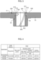
- FIG. 3 is a side sectional view of the auxiliary bearing used in the two-cylinder hermetic compressor according to the exemplary embodiment of the present invention.
- shaft 40 is constituted by main shaft portion 41, first eccentric portion 42, second eccentric portion 43, auxiliary shaft portion 44, and connection shaft portion 45.
- Thrust receiving portion 46 is provided on a side of second eccentric portion 43 facing auxiliary shaft portion 44.
- auxiliary bearing 53 is provided with thrust surfaces 53A, 53B on which the end face of thrust receiving portion 46 illustrated in FIG. 2 slides while contacting therewith.
- Thrust surfaces 53A, 53B are provided with ring groove 60.
- Thrust surface 53A is defined by the end face of auxiliary bearing 53 on an inner periphery side with respect to ring groove 60
- thrust surface 53B is defined by the end face of auxiliary bearing 53 on an outer periphery side with respect to ring groove 60.
- ring groove 60 is formed on thrust surfaces 53A, 53B, maximum stress exerted on auxiliary shaft portion 44 is reduced, whereby an amount of sliding frictional wear on auxiliary shaft portion 44 can be suppressed.
- ring-shaped edge portions 61A, 61B formed by ring groove 60 and thrust surfaces 53A, 53B are beveled. Note that ring-shaped edge portion 61A is an inner peripheral edge of ring groove 60, and ring-shaped edge portion 61B is an outer peripheral edge of ring groove 60.
- the end face (thrust surface 53A) of auxiliary bearing 53 on the inner periphery side with respect to ring groove 60 is formed to be lower than the end face (thrust surface 53B) of auxiliary bearing 53 on the outer periphery side with respect to ring groove 60 by h1 (step h1), the end face of thrust receiving portion 46 is prevented from being contact with thrust surface 53A, and the end face (thrust surface 53B) of auxiliary bearing 53 on the outer periphery side with respect to ring groove 60 is defined as a thrust surface.
- Step h1 between thrust surface 53A and thrust surface 53B is smaller than depth h2 of ring groove 60.
- the configuration in which the end face of auxiliary bearing 53 on the inner periphery side with respect to ring groove 60 is prevented from being in contact with the end face of thrust receiving portion 46 can prevent abnormal wear on the end face of thrust receiving portion 46 caused by ring-shaped edge portion 61A of auxiliary bearing 53 on the inner periphery side with respect to ring groove 60.
- the diameter of main shaft portion 41 is defined as d1
- the diameter of first eccentric portion 42 is defined as d2
- the diameter of second eccentric portion 43 is defined as d3
- the diameter of auxiliary shaft portion 44 is defined as d4
- the diameter of connection shaft portion 45 is defined as d5
- diameter d4 of auxiliary shaft portion 44 is set smaller than diameter d1 of main shaft portion 41.
- diameter d6 of thrust receiving portion 46 is set smaller than diameter d3 of second eccentric portion 43, and larger than diameter d1 of main shaft portion 41, diameter d5 of connection shaft portion 45, and diameter d4 of auxiliary shaft portion 44.
- auxiliary shaft portion 44 can be made smaller than diameter d1 of main shaft portion 41, whereby a sliding loss on auxiliary shaft portion 44 can be reduced.
- auxiliary shaft portion 44 is set smaller as described above in the configuration in which the thrust load of shaft 40 is received by auxiliary shaft portion 44, the area that receives the thrust load of shaft 40 becomes small, so that the load cannot stably be received.
- first communication path 12A which is in communication with oil feed path 47 formed inside shaft 40 is open at the end of main shaft portion 41 on the side of first eccentric portion 42
- second communication path 12B which is in communication with oil feed path 47 formed inside shaft 40 is open at the end of auxiliary shaft portion 44 on the side of second eccentric portion 43.
- the diameter is set to be smaller than diameter d1 of main shaft portion 41 on the position where first communication path 12A is open, and the diameter is set to be smaller than diameter d4 of auxiliary shaft portion 44 on the position where second communication path 12B is open, whereby oil can be reliably fed to compression mechanism unit 30.
- Third communication path 12C which is in communication with oil feed path 47 formed inside shaft 40 is open at the side surface of first eccentric portion 42
- fourth communication path 12D which is in communication with oil feed path 47 formed inside shaft 40 is open at the side surface of second eccentric portion 43.
- the thrust load of shaft 40 is received by the area of auxiliary shaft portion 44 excluding the area of oil feed path 47, because oil feed path 47 is formed inside shaft 40.
- the thrust load of shaft 40 is received on the end face of thrust receiving portion 46. Therefore, even if diameter d4 of auxiliary shaft portion 44 is made smaller than diameter d1 of main shaft portion 41, that is, even if diameter d4 of auxiliary shaft portion 44 is set smaller, it is unnecessary to decrease the area that receives the thrust load of shaft 40, whereby the thrust load of shaft 40 can stably be received.
- the height of thrust receiving portion 46 is defined as h3
- the height of a shaft diameter portion, which has a diameter smaller than diameter d4 of auxiliary shaft portion 44 and on which second communication path 12B is open is defined as h4
- height h4 of the shaft diameter portion is larger than step h1 between thrust surface 53A and thrust surface 53B
- depth h2 of ring groove 60 is larger than height h4 of the shaft diameter portion.
- oil groove 53D for guiding oil is formed on inner peripheral surface 53C of auxiliary bearing 53 on which the outer peripheral surface of auxiliary shaft portion 44 slides.
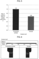
- FIGS. 4 to 6 illustrate test results of maximum stress values on the auxiliary shaft portion in the two-cylinder hermetic compressor according to the exemplary embodiment of the present invention.
- FIG. 4 shows specifications of Comparative Example in which diameter d1 of main shaft portion 41 and diameter d4 of auxiliary shaft portion 44 are the same and ring groove 60 is not formed, and Example in which diameter d4 of auxiliary shaft portion 44 is set smaller than diameter d1 of main shaft portion 41 and ring groove 60 is formed.
- diameter d4 of auxiliary shaft portion 44 is set to be 94% with respect to diameter d1 of main shaft portion 41.
- FIG. 5 is a graph showing the test result of maximum stress values on auxiliary shaft portions 44 in Comparative Example and Example
- FIG. 6 is an analysis diagram showing a stress distribution on auxiliary shaft portions 44 in Comparative Example and Example.
- While the present invention is a two-cylinder hermetic compressor, it is also applicable to a compressor provided with a plurality of, such as three or more, cylinders.
Landscapes
- Engineering & Computer Science (AREA)
- Mechanical Engineering (AREA)
- General Engineering & Computer Science (AREA)
- Applications Or Details Of Rotary Compressors (AREA)
- Compressor (AREA)
Claims (2)
- Hermetischer Zweizylinder-Kompressor (1), umfassend:eine Elektromotoreinheit (20) und eine Kompressionseinrichtungseinheit (30) in einem geschlossenen Behälter (10), wobei die Elektromotoreinheit (20) und die Kompressionseinrichtungseinheit (30) durch eine Welle (40) miteinander verbunden sind,wobei die Elektromotoreinheit (20) einen an einer Innenfläche des versiegelten Behälters (10) befestigten Stator (21) und einen in dem Stator (21) rotierenden Rotor (22) umfasst,eine erste Kompressionseinrichtungseinheit (30A) und eine zweite Kompressionseinrichtungseinheit (30B) als Kompressionseinrichtungseinheit (30) vorgesehen sind,die erste Kompressionseinrichtungseinheit (30A) einen ersten Zylinder (31A) und einen in dem ersten Zylinder (31A) vorgesehenen ersten Kolben (32A) umfasst,die zweite Kompressionseinrichtungseinheit (30B) einen zweiten Zylinder (31B) und einen in dem zweiten Zylinder (31B) vorgesehenen zweiten Kolben (32B) umfasst,ein Hauptlager (51) auf einer Oberfläche des ersten Zylinders (31A) angeordnet ist und eine Zwischenplatte (52) auf einer weiteren Oberfläche des ersten Zylinders (31A) angeordnet ist,wobei die Zwischenplatte (52) auf einer Oberfläche des zweiten Zylinders (31B) angeordnet ist und ein Hilfslager (53) auf einer weiteren Oberfläche des zweiten Zylinders (31B) angeordnet ist,wobei die Welle (40) einen Hauptwellenabschnitt (41), an dem der Rotor (22) befestigt ist und der von dem Hauptlager (51) gestützt ist, einen ersten exzentrischen Abschnitt (42), an dem der erste Kolben (32A) montiert ist, einen zweiten exzentrischen Abschnitt (43), an dem der zweite Kolben (32B) montiert ist, und einen Hilfswellenabschnitt (44), der von dem Hilfslager (53) gestützt ist, aufweist,wobei auf einer Seite des zweiten exzentrischen Abschnitts (43), die dem Hilfswellenabschnitt (44) zugewandt ist, ein Axialdruckaufnahmeabschnitt (46) vorgesehen ist,wobei das Hilfslager (53) mit einer ersten und einer zweiten Axialdruckfläche (53A, 53B) versehen ist, auf denen eine Endfläche des Axialdruckaufnahmeabschnitts (46) gleitet, während die Endfläche in Kontakt mit den Axialdruckflächen (53A, 53B) ist,wobei die Axialdruckflächen (53A, 53B) mit einer Ringnut (60) ausgebildet sind,wobei eine Endfläche des Hilfslagers (53) an einer Innenumfangsseite in Bezug auf die Ringnut (60) als erste Axialdruckfläche (53A) definiert ist,wobei eine Endfläche des Hilfslagers (53) an einer Außenumfangsseite in Bezug auf die Ringnut (60) als zweite Axialdruckfläche (53B) definiert ist, undwobei die erste Axialdruckfläche (53A) niedriger als die zweite Axialdruckfläche (53B) ausgebildet ist und die erste Axialdruckfläche (53A) daran gehindert ist, mit der Endfläche des Axialdruckaufnahmeabschnitts (46) in Kontakt zu kommen,dadurch gekennzeichnet, dass, wenn ein Durchmesser des Hauptwellenabschnitts (41) als d1 definiert ist, ein Durchmesser des ersten exzentrischen Abschnitts (42) als d2 definiert ist, ein Durchmesser des zweiten exzentrischen Abschnitts (43) als d3 definiert ist, ein Durchmesser des Hilfswellenabschnitts (44) als d4 definiert ist, ein Durchmesser des Verbindungswellenabschnitts (45) als d5 definiert ist und ein Durchmesser des Axialdruckaufnahmeabschnitts (46) als d6 definiert ist,der Durchmesser d4 des Hilfswellenabschnitts (44) kleiner eingestellt ist als der Durchmesser d1 des Hauptwellenabschnitts (41), undder Durchmesser d6 des Axialdruckaufnahmeabschnitts (46)(i) kleiner als der Durchmesser d3 des zweiten exzentrischen Abschnitts (43), und(ii) größer als der Durchmesser d1 des Hauptwellenabschnitts (41), der Durchmesser d5 des Verbindungswellenabschnitts (45) und der Durchmesser d4 des Nebenwellenabschnitts (44) eingestellt ist.
- Hermetischer Zweizylinder-Kompressor (1) nach Anspruch 1, wobei ein erster ringförmiger Randabschnitt (61A) ein innerer Umfangsrand der Ringnut (60) ist und ein zweiter ringförmiger Randabschnitt (61B) ein äußerer Umfangsrand der Ringnut (60) ist, und der erste und der zweite ringförmige Randabschnitt (61A, 61B) abgeschrägt sind.
Applications Claiming Priority (1)
| Application Number | Priority Date | Filing Date | Title |
|---|---|---|---|
| JP2016035037A JP7002033B2 (ja) | 2016-02-26 | 2016-02-26 | 2シリンダ型密閉圧縮機 |
Publications (2)
| Publication Number | Publication Date |
|---|---|
| EP3214263A1 EP3214263A1 (de) | 2017-09-06 |
| EP3214263B1 true EP3214263B1 (de) | 2024-07-24 |
Family
ID=57909502
Family Applications (1)
| Application Number | Title | Priority Date | Filing Date |
|---|---|---|---|
| EP17153366.4A Active EP3214263B1 (de) | 2016-02-26 | 2017-01-26 | Hermetischer zwei-zylinder-verdichter |
Country Status (4)
| Country | Link |
|---|---|
| US (1) | US10273957B2 (de) |
| EP (1) | EP3214263B1 (de) |
| JP (1) | JP7002033B2 (de) |
| CN (1) | CN107131125A (de) |
Families Citing this family (7)
| Publication number | Priority date | Publication date | Assignee | Title |
|---|---|---|---|---|
| JP6489173B2 (ja) * | 2017-08-09 | 2019-03-27 | ダイキン工業株式会社 | ロータリ圧縮機 |
| JP6432657B1 (ja) * | 2017-08-24 | 2018-12-05 | 株式会社富士通ゼネラル | ロータリ圧縮機 |
| CN108087284B (zh) * | 2017-12-01 | 2019-10-18 | 珠海格力电器股份有限公司 | 泵体组件、压缩机及空调器 |
| JP7186242B2 (ja) * | 2018-12-12 | 2022-12-08 | 東芝キヤリア株式会社 | 回転式圧縮機および冷凍サイクル装置 |
| WO2021019750A1 (ja) * | 2019-07-31 | 2021-02-04 | 東芝キヤリア株式会社 | 密閉型圧縮機、および冷凍サイクル装置 |
| CN112502973B (zh) * | 2020-11-18 | 2022-06-24 | 珠海格力节能环保制冷技术研究中心有限公司 | 泵体组件、压缩机和空调器 |
| CN113653645A (zh) * | 2021-09-23 | 2021-11-16 | 广东美芝精密制造有限公司 | 一种泵体和压缩机 |
Family Cites Families (18)
| Publication number | Priority date | Publication date | Assignee | Title |
|---|---|---|---|---|
| US2988267A (en) * | 1957-12-23 | 1961-06-13 | Gen Electric | Rotary compressor lubricating arrangement |
| US4640669A (en) * | 1984-11-13 | 1987-02-03 | Tecumseh Products Company | Rotary compressor lubrication arrangement |
| JPS6270686A (ja) * | 1985-09-20 | 1987-04-01 | Sanyo Electric Co Ltd | 多気筒回転圧縮機 |
| JP2004124834A (ja) | 2002-10-03 | 2004-04-22 | Mitsubishi Electric Corp | 密閉型ロータリ圧縮機 |
| CN2934666Y (zh) * | 2006-04-28 | 2007-08-15 | 西安庆安制冷设备股份有限公司 | 一种滚动活塞式压缩机 |
| JP4864572B2 (ja) * | 2006-07-03 | 2012-02-01 | 東芝キヤリア株式会社 | 回転式圧縮機及びこれを用いた冷凍サイクル装置 |
| CN101772649B (zh) * | 2007-09-07 | 2012-08-22 | 东芝开利株式会社 | 双汽缸旋转式压缩机及制冷循环装置 |
| CN102046981A (zh) * | 2008-05-28 | 2011-05-04 | 东芝开利株式会社 | 密闭型压缩机以及制冷循环装置 |
| JP4655166B2 (ja) * | 2009-08-06 | 2011-03-23 | ダイキン工業株式会社 | 圧縮機 |
| WO2011030809A1 (ja) * | 2009-09-11 | 2011-03-17 | 東芝キヤリア株式会社 | 多気筒ロータリ式圧縮機と冷凍サイクル装置 |
| JP5449999B2 (ja) * | 2009-11-26 | 2014-03-19 | 東芝キヤリア株式会社 | 密閉型圧縮機と冷凍サイクル装置 |
| JP5556450B2 (ja) * | 2010-07-02 | 2014-07-23 | パナソニック株式会社 | 回転式圧縮機 |
| JP5263360B2 (ja) * | 2011-09-26 | 2013-08-14 | ダイキン工業株式会社 | 圧縮機 |
| JP6022247B2 (ja) * | 2011-09-29 | 2016-11-09 | 東芝キヤリア株式会社 | 密閉型圧縮機及び冷凍サイクル装置 |
| CN202926630U (zh) * | 2012-11-14 | 2013-05-08 | 广东美芝制冷设备有限公司 | 旋转式压缩机和多气缸旋转式压缩机 |
| JP6066801B2 (ja) * | 2013-03-29 | 2017-01-25 | 三菱電機株式会社 | 密閉型回転圧縮機 |
| CN206299566U (zh) * | 2014-08-01 | 2017-07-04 | 东芝开利株式会社 | 旋转式压缩机及冷冻循环装置 |
| CN206017154U (zh) * | 2016-09-13 | 2017-03-15 | 西安庆安制冷设备股份有限公司 | 一种转子式压缩机结构 |
-
2016
- 2016-02-26 JP JP2016035037A patent/JP7002033B2/ja active Active
-
2017
- 2017-01-26 EP EP17153366.4A patent/EP3214263B1/de active Active
- 2017-02-08 US US15/427,899 patent/US10273957B2/en active Active
- 2017-02-20 CN CN201710090056.4A patent/CN107131125A/zh active Pending
Also Published As
| Publication number | Publication date |
|---|---|
| JP7002033B2 (ja) | 2022-01-20 |
| US20170248139A1 (en) | 2017-08-31 |
| EP3214263A1 (de) | 2017-09-06 |
| CN107131125A (zh) | 2017-09-05 |
| JP2017150424A (ja) | 2017-08-31 |
| US10273957B2 (en) | 2019-04-30 |
Similar Documents
| Publication | Publication Date | Title |
|---|---|---|
| EP3214263B1 (de) | Hermetischer zwei-zylinder-verdichter | |
| EP3214312B1 (de) | Hermetischer zwei-zylinder-verdichter | |
| EP2762727B1 (de) | Spiralverdichter | |
| EP2947321A1 (de) | Mehrzylindriger rotationsverdichter | |
| US20130171017A1 (en) | Rotary compressor with dual eccentric portion | |
| CN103982437B (zh) | 容积型压缩机 | |
| WO2019044867A1 (ja) | スクロール型圧縮機 | |
| US11313367B2 (en) | Rotary compressor with roller oil groove | |
| EP3647595B1 (de) | Rotationsverdichter | |
| EP2206925A1 (de) | Rotierende strömungsmaschine | |
| EP3211233B1 (de) | Zweizylinder hermetischer kompressor | |
| JP6869378B2 (ja) | ロータリ圧縮機 | |
| KR20160132802A (ko) | 밀폐형 압축기 | |
| JP2017053263A (ja) | ロータリ圧縮機 | |
| KR101738460B1 (ko) | 밀폐형 압축기 | |
| KR20200004748A (ko) | 스크롤 압축기 | |
| WO2018168344A1 (ja) | ロータリー式圧縮機 | |
| EP3217014A1 (de) | Verdichter | |
| JP2015105616A (ja) | 回転式圧縮機 | |
| WO2020230230A1 (ja) | ロータリ圧縮機 | |
| JP2009174382A (ja) | 圧縮機 | |
| CN106662093A (zh) | 开放型压缩机 |
Legal Events
| Date | Code | Title | Description |
|---|---|---|---|
| PUAI | Public reference made under article 153(3) epc to a published international application that has entered the european phase |
Free format text: ORIGINAL CODE: 0009012 |
|
| STAA | Information on the status of an ep patent application or granted ep patent |
Free format text: STATUS: THE APPLICATION HAS BEEN PUBLISHED |
|
| AK | Designated contracting states |
Kind code of ref document: A1 Designated state(s): AL AT BE BG CH CY CZ DE DK EE ES FI FR GB GR HR HU IE IS IT LI LT LU LV MC MK MT NL NO PL PT RO RS SE SI SK SM TR |
|
| AX | Request for extension of the european patent |
Extension state: BA ME |
|
| STAA | Information on the status of an ep patent application or granted ep patent |
Free format text: STATUS: REQUEST FOR EXAMINATION WAS MADE |
|
| 17P | Request for examination filed |
Effective date: 20180306 |
|
| RBV | Designated contracting states (corrected) |
Designated state(s): AL AT BE BG CH CY CZ DE DK EE ES FI FR GB GR HR HU IE IS IT LI LT LU LV MC MK MT NL NO PL PT RO RS SE SI SK SM TR |
|
| STAA | Information on the status of an ep patent application or granted ep patent |
Free format text: STATUS: EXAMINATION IS IN PROGRESS |
|
| 17Q | First examination report despatched |
Effective date: 20200930 |
|
| GRAP | Despatch of communication of intention to grant a patent |
Free format text: ORIGINAL CODE: EPIDOSNIGR1 |
|
| STAA | Information on the status of an ep patent application or granted ep patent |
Free format text: STATUS: GRANT OF PATENT IS INTENDED |
|
| INTG | Intention to grant announced |
Effective date: 20240216 |
|
| GRAS | Grant fee paid |
Free format text: ORIGINAL CODE: EPIDOSNIGR3 |
|
| GRAA | (expected) grant |
Free format text: ORIGINAL CODE: 0009210 |
|
| STAA | Information on the status of an ep patent application or granted ep patent |
Free format text: STATUS: THE PATENT HAS BEEN GRANTED |
|
| AK | Designated contracting states |
Kind code of ref document: B1 Designated state(s): AL AT BE BG CH CY CZ DE DK EE ES FI FR GB GR HR HU IE IS IT LI LT LU LV MC MK MT NL NO PL PT RO RS SE SI SK SM TR |
|
| REG | Reference to a national code |
Ref country code: GB Ref legal event code: FG4D |
|
| REG | Reference to a national code |
Ref country code: CH Ref legal event code: EP |
|
| REG | Reference to a national code |
Ref country code: IE Ref legal event code: FG4D Ref country code: DE Ref legal event code: R096 Ref document number: 602017083466 Country of ref document: DE |
|
| REG | Reference to a national code |
Ref country code: LT Ref legal event code: MG9D |
|
| REG | Reference to a national code |
Ref country code: NL Ref legal event code: MP Effective date: 20240724 |
|
| PG25 | Lapsed in a contracting state [announced via postgrant information from national office to epo] |
Ref country code: PT Free format text: LAPSE BECAUSE OF FAILURE TO SUBMIT A TRANSLATION OF THE DESCRIPTION OR TO PAY THE FEE WITHIN THE PRESCRIBED TIME-LIMIT Effective date: 20241125 |
|
| REG | Reference to a national code |
Ref country code: AT Ref legal event code: MK05 Ref document number: 1706477 Country of ref document: AT Kind code of ref document: T Effective date: 20240724 |
|
| PG25 | Lapsed in a contracting state [announced via postgrant information from national office to epo] |
Ref country code: NL Free format text: LAPSE BECAUSE OF FAILURE TO SUBMIT A TRANSLATION OF THE DESCRIPTION OR TO PAY THE FEE WITHIN THE PRESCRIBED TIME-LIMIT Effective date: 20240724 |
|
| PG25 | Lapsed in a contracting state [announced via postgrant information from national office to epo] |
Ref country code: PT Free format text: LAPSE BECAUSE OF FAILURE TO SUBMIT A TRANSLATION OF THE DESCRIPTION OR TO PAY THE FEE WITHIN THE PRESCRIBED TIME-LIMIT Effective date: 20241125 Ref country code: NL Free format text: LAPSE BECAUSE OF FAILURE TO SUBMIT A TRANSLATION OF THE DESCRIPTION OR TO PAY THE FEE WITHIN THE PRESCRIBED TIME-LIMIT Effective date: 20240724 |
|
| PG25 | Lapsed in a contracting state [announced via postgrant information from national office to epo] |
Ref country code: NO Free format text: LAPSE BECAUSE OF FAILURE TO SUBMIT A TRANSLATION OF THE DESCRIPTION OR TO PAY THE FEE WITHIN THE PRESCRIBED TIME-LIMIT Effective date: 20241024 |
|
| PG25 | Lapsed in a contracting state [announced via postgrant information from national office to epo] |
Ref country code: PL Free format text: LAPSE BECAUSE OF FAILURE TO SUBMIT A TRANSLATION OF THE DESCRIPTION OR TO PAY THE FEE WITHIN THE PRESCRIBED TIME-LIMIT Effective date: 20240724 Ref country code: FI Free format text: LAPSE BECAUSE OF FAILURE TO SUBMIT A TRANSLATION OF THE DESCRIPTION OR TO PAY THE FEE WITHIN THE PRESCRIBED TIME-LIMIT Effective date: 20240724 Ref country code: GR Free format text: LAPSE BECAUSE OF FAILURE TO SUBMIT A TRANSLATION OF THE DESCRIPTION OR TO PAY THE FEE WITHIN THE PRESCRIBED TIME-LIMIT Effective date: 20241025 |
|
| PG25 | Lapsed in a contracting state [announced via postgrant information from national office to epo] |
Ref country code: BG Free format text: LAPSE BECAUSE OF FAILURE TO SUBMIT A TRANSLATION OF THE DESCRIPTION OR TO PAY THE FEE WITHIN THE PRESCRIBED TIME-LIMIT Effective date: 20240724 |
|
| PG25 | Lapsed in a contracting state [announced via postgrant information from national office to epo] |
Ref country code: LV Free format text: LAPSE BECAUSE OF FAILURE TO SUBMIT A TRANSLATION OF THE DESCRIPTION OR TO PAY THE FEE WITHIN THE PRESCRIBED TIME-LIMIT Effective date: 20240724 |
|
| PG25 | Lapsed in a contracting state [announced via postgrant information from national office to epo] |
Ref country code: IS Free format text: LAPSE BECAUSE OF FAILURE TO SUBMIT A TRANSLATION OF THE DESCRIPTION OR TO PAY THE FEE WITHIN THE PRESCRIBED TIME-LIMIT Effective date: 20241124 Ref country code: AT Free format text: LAPSE BECAUSE OF FAILURE TO SUBMIT A TRANSLATION OF THE DESCRIPTION OR TO PAY THE FEE WITHIN THE PRESCRIBED TIME-LIMIT Effective date: 20240724 |
|
| PG25 | Lapsed in a contracting state [announced via postgrant information from national office to epo] |
Ref country code: HR Free format text: LAPSE BECAUSE OF FAILURE TO SUBMIT A TRANSLATION OF THE DESCRIPTION OR TO PAY THE FEE WITHIN THE PRESCRIBED TIME-LIMIT Effective date: 20240724 |
|
| PG25 | Lapsed in a contracting state [announced via postgrant information from national office to epo] |
Ref country code: RS Free format text: LAPSE BECAUSE OF FAILURE TO SUBMIT A TRANSLATION OF THE DESCRIPTION OR TO PAY THE FEE WITHIN THE PRESCRIBED TIME-LIMIT Effective date: 20241024 Ref country code: ES Free format text: LAPSE BECAUSE OF FAILURE TO SUBMIT A TRANSLATION OF THE DESCRIPTION OR TO PAY THE FEE WITHIN THE PRESCRIBED TIME-LIMIT Effective date: 20240724 |
|
| PG25 | Lapsed in a contracting state [announced via postgrant information from national office to epo] |
Ref country code: RS Free format text: LAPSE BECAUSE OF FAILURE TO SUBMIT A TRANSLATION OF THE DESCRIPTION OR TO PAY THE FEE WITHIN THE PRESCRIBED TIME-LIMIT Effective date: 20241024 Ref country code: PL Free format text: LAPSE BECAUSE OF FAILURE TO SUBMIT A TRANSLATION OF THE DESCRIPTION OR TO PAY THE FEE WITHIN THE PRESCRIBED TIME-LIMIT Effective date: 20240724 Ref country code: NO Free format text: LAPSE BECAUSE OF FAILURE TO SUBMIT A TRANSLATION OF THE DESCRIPTION OR TO PAY THE FEE WITHIN THE PRESCRIBED TIME-LIMIT Effective date: 20241024 Ref country code: LV Free format text: LAPSE BECAUSE OF FAILURE TO SUBMIT A TRANSLATION OF THE DESCRIPTION OR TO PAY THE FEE WITHIN THE PRESCRIBED TIME-LIMIT Effective date: 20240724 Ref country code: IS Free format text: LAPSE BECAUSE OF FAILURE TO SUBMIT A TRANSLATION OF THE DESCRIPTION OR TO PAY THE FEE WITHIN THE PRESCRIBED TIME-LIMIT Effective date: 20241124 Ref country code: HR Free format text: LAPSE BECAUSE OF FAILURE TO SUBMIT A TRANSLATION OF THE DESCRIPTION OR TO PAY THE FEE WITHIN THE PRESCRIBED TIME-LIMIT Effective date: 20240724 Ref country code: GR Free format text: LAPSE BECAUSE OF FAILURE TO SUBMIT A TRANSLATION OF THE DESCRIPTION OR TO PAY THE FEE WITHIN THE PRESCRIBED TIME-LIMIT Effective date: 20241025 Ref country code: FI Free format text: LAPSE BECAUSE OF FAILURE TO SUBMIT A TRANSLATION OF THE DESCRIPTION OR TO PAY THE FEE WITHIN THE PRESCRIBED TIME-LIMIT Effective date: 20240724 Ref country code: ES Free format text: LAPSE BECAUSE OF FAILURE TO SUBMIT A TRANSLATION OF THE DESCRIPTION OR TO PAY THE FEE WITHIN THE PRESCRIBED TIME-LIMIT Effective date: 20240724 Ref country code: BG Free format text: LAPSE BECAUSE OF FAILURE TO SUBMIT A TRANSLATION OF THE DESCRIPTION OR TO PAY THE FEE WITHIN THE PRESCRIBED TIME-LIMIT Effective date: 20240724 Ref country code: AT Free format text: LAPSE BECAUSE OF FAILURE TO SUBMIT A TRANSLATION OF THE DESCRIPTION OR TO PAY THE FEE WITHIN THE PRESCRIBED TIME-LIMIT Effective date: 20240724 |
|
| PG25 | Lapsed in a contracting state [announced via postgrant information from national office to epo] |
Ref country code: RO Free format text: LAPSE BECAUSE OF FAILURE TO SUBMIT A TRANSLATION OF THE DESCRIPTION OR TO PAY THE FEE WITHIN THE PRESCRIBED TIME-LIMIT Effective date: 20240724 Ref country code: DK Free format text: LAPSE BECAUSE OF FAILURE TO SUBMIT A TRANSLATION OF THE DESCRIPTION OR TO PAY THE FEE WITHIN THE PRESCRIBED TIME-LIMIT Effective date: 20240724 Ref country code: SM Free format text: LAPSE BECAUSE OF FAILURE TO SUBMIT A TRANSLATION OF THE DESCRIPTION OR TO PAY THE FEE WITHIN THE PRESCRIBED TIME-LIMIT Effective date: 20240724 |
|
| PG25 | Lapsed in a contracting state [announced via postgrant information from national office to epo] |
Ref country code: EE Free format text: LAPSE BECAUSE OF FAILURE TO SUBMIT A TRANSLATION OF THE DESCRIPTION OR TO PAY THE FEE WITHIN THE PRESCRIBED TIME-LIMIT Effective date: 20240724 |
|
| PG25 | Lapsed in a contracting state [announced via postgrant information from national office to epo] |
Ref country code: CZ Free format text: LAPSE BECAUSE OF FAILURE TO SUBMIT A TRANSLATION OF THE DESCRIPTION OR TO PAY THE FEE WITHIN THE PRESCRIBED TIME-LIMIT Effective date: 20240724 |
|
| REG | Reference to a national code |
Ref country code: DE Ref legal event code: R097 Ref document number: 602017083466 Country of ref document: DE |
|
| PG25 | Lapsed in a contracting state [announced via postgrant information from national office to epo] |
Ref country code: IT Free format text: LAPSE BECAUSE OF FAILURE TO SUBMIT A TRANSLATION OF THE DESCRIPTION OR TO PAY THE FEE WITHIN THE PRESCRIBED TIME-LIMIT Effective date: 20240724 Ref country code: SK Free format text: LAPSE BECAUSE OF FAILURE TO SUBMIT A TRANSLATION OF THE DESCRIPTION OR TO PAY THE FEE WITHIN THE PRESCRIBED TIME-LIMIT Effective date: 20240724 |
|
| PLBE | No opposition filed within time limit |
Free format text: ORIGINAL CODE: 0009261 |
|
| STAA | Information on the status of an ep patent application or granted ep patent |
Free format text: STATUS: NO OPPOSITION FILED WITHIN TIME LIMIT |
|
| 26N | No opposition filed |
Effective date: 20250425 |
|
| REG | Reference to a national code |
Ref country code: CH Ref legal event code: PL |
|
| PG25 | Lapsed in a contracting state [announced via postgrant information from national office to epo] |
Ref country code: SE Free format text: LAPSE BECAUSE OF FAILURE TO SUBMIT A TRANSLATION OF THE DESCRIPTION OR TO PAY THE FEE WITHIN THE PRESCRIBED TIME-LIMIT Effective date: 20240724 |
|
| PG25 | Lapsed in a contracting state [announced via postgrant information from national office to epo] |
Ref country code: MC Free format text: LAPSE BECAUSE OF FAILURE TO SUBMIT A TRANSLATION OF THE DESCRIPTION OR TO PAY THE FEE WITHIN THE PRESCRIBED TIME-LIMIT Effective date: 20240724 Ref country code: LU Free format text: LAPSE BECAUSE OF NON-PAYMENT OF DUE FEES Effective date: 20250126 |
|
| GBPC | Gb: european patent ceased through non-payment of renewal fee |
Effective date: 20250126 |
|
| PG25 | Lapsed in a contracting state [announced via postgrant information from national office to epo] |
Ref country code: BE Free format text: LAPSE BECAUSE OF NON-PAYMENT OF DUE FEES Effective date: 20250131 Ref country code: GB Free format text: LAPSE BECAUSE OF NON-PAYMENT OF DUE FEES Effective date: 20250126 |
|
| PG25 | Lapsed in a contracting state [announced via postgrant information from national office to epo] |
Ref country code: FR Free format text: LAPSE BECAUSE OF NON-PAYMENT OF DUE FEES Effective date: 20250131 |
|
| PG25 | Lapsed in a contracting state [announced via postgrant information from national office to epo] |
Ref country code: CH Free format text: LAPSE BECAUSE OF NON-PAYMENT OF DUE FEES Effective date: 20250131 |
|
| REG | Reference to a national code |
Ref country code: BE Ref legal event code: MM Effective date: 20250131 |
|
| PG25 | Lapsed in a contracting state [announced via postgrant information from national office to epo] |
Ref country code: IE Free format text: LAPSE BECAUSE OF NON-PAYMENT OF DUE FEES Effective date: 20250126 |
|
| PGFP | Annual fee paid to national office [announced via postgrant information from national office to epo] |
Ref country code: DE Payment date: 20260121 Year of fee payment: 10 |