EP3214284B1 - Système d'échappement en particulier pour un moteur à combustion interne d'un véhicule automobile - Google Patents
Système d'échappement en particulier pour un moteur à combustion interne d'un véhicule automobile Download PDFInfo
- Publication number
- EP3214284B1 EP3214284B1 EP17150122.4A EP17150122A EP3214284B1 EP 3214284 B1 EP3214284 B1 EP 3214284B1 EP 17150122 A EP17150122 A EP 17150122A EP 3214284 B1 EP3214284 B1 EP 3214284B1
- Authority
- EP
- European Patent Office
- Prior art keywords
- reactant
- exhaust gas
- heating
- heating element
- accordance
- Prior art date
- Legal status (The legal status is an assumption and is not a legal conclusion. Google has not performed a legal analysis and makes no representation as to the accuracy of the status listed.)
- Active
Links
Images





Classifications
-
- F—MECHANICAL ENGINEERING; LIGHTING; HEATING; WEAPONS; BLASTING
- F01—MACHINES OR ENGINES IN GENERAL; ENGINE PLANTS IN GENERAL; STEAM ENGINES
- F01N—GAS-FLOW SILENCERS OR EXHAUST APPARATUS FOR MACHINES OR ENGINES IN GENERAL; GAS-FLOW SILENCERS OR EXHAUST APPARATUS FOR INTERNAL-COMBUSTION ENGINES
- F01N3/00—Exhaust or silencing apparatus having means for purifying, rendering innocuous, or otherwise treating exhaust
- F01N3/08—Exhaust or silencing apparatus having means for purifying, rendering innocuous, or otherwise treating exhaust for rendering innocuous
- F01N3/10—Exhaust or silencing apparatus having means for purifying, rendering innocuous, or otherwise treating exhaust for rendering innocuous by thermal or catalytic conversion of noxious components of exhaust
- F01N3/18—Exhaust or silencing apparatus having means for purifying, rendering innocuous, or otherwise treating exhaust for rendering innocuous by thermal or catalytic conversion of noxious components of exhaust characterised by methods of operation; Control
- F01N3/20—Exhaust or silencing apparatus having means for purifying, rendering innocuous, or otherwise treating exhaust for rendering innocuous by thermal or catalytic conversion of noxious components of exhaust characterised by methods of operation; Control specially adapted for catalytic conversion
- F01N3/206—Adding periodically or continuously substances to exhaust gases for promoting purification, e.g. catalytic material in liquid form, NOx reducing agents
- F01N3/2066—Selective catalytic reduction [SCR]
-
- F—MECHANICAL ENGINEERING; LIGHTING; HEATING; WEAPONS; BLASTING
- F01—MACHINES OR ENGINES IN GENERAL; ENGINE PLANTS IN GENERAL; STEAM ENGINES
- F01N—GAS-FLOW SILENCERS OR EXHAUST APPARATUS FOR MACHINES OR ENGINES IN GENERAL; GAS-FLOW SILENCERS OR EXHAUST APPARATUS FOR INTERNAL-COMBUSTION ENGINES
- F01N3/00—Exhaust or silencing apparatus having means for purifying, rendering innocuous, or otherwise treating exhaust
- F01N3/08—Exhaust or silencing apparatus having means for purifying, rendering innocuous, or otherwise treating exhaust for rendering innocuous
- F01N3/10—Exhaust or silencing apparatus having means for purifying, rendering innocuous, or otherwise treating exhaust for rendering innocuous by thermal or catalytic conversion of noxious components of exhaust
- F01N3/24—Exhaust or silencing apparatus having means for purifying, rendering innocuous, or otherwise treating exhaust for rendering innocuous by thermal or catalytic conversion of noxious components of exhaust characterised by constructional aspects of converting apparatus
- F01N3/28—Construction of catalytic reactors
- F01N3/2892—Exhaust flow directors or the like, e.g. upstream of catalytic device
-
- H—ELECTRICITY
- H05—ELECTRIC TECHNIQUES NOT OTHERWISE PROVIDED FOR
- H05B—ELECTRIC HEATING; ELECTRIC LIGHT SOURCES NOT OTHERWISE PROVIDED FOR; CIRCUIT ARRANGEMENTS FOR ELECTRIC LIGHT SOURCES, IN GENERAL
- H05B3/00—Ohmic-resistance heating
- H05B3/20—Heating elements having extended surface area substantially in a two-dimensional [2D] plane, e.g. plate-heater
-
- F—MECHANICAL ENGINEERING; LIGHTING; HEATING; WEAPONS; BLASTING
- F01—MACHINES OR ENGINES IN GENERAL; ENGINE PLANTS IN GENERAL; STEAM ENGINES
- F01N—GAS-FLOW SILENCERS OR EXHAUST APPARATUS FOR MACHINES OR ENGINES IN GENERAL; GAS-FLOW SILENCERS OR EXHAUST APPARATUS FOR INTERNAL-COMBUSTION ENGINES
- F01N2240/00—Combination or association of two or more different exhaust treating devices, or of at least one such device with an auxiliary device, not covered by indexing codes F01N2230/00 or F01N2250/00, one of the devices being
- F01N2240/16—Combination or association of two or more different exhaust treating devices, or of at least one such device with an auxiliary device, not covered by indexing codes F01N2230/00 or F01N2250/00, one of the devices being an electric heater, i.e. a resistance heater
-
- F—MECHANICAL ENGINEERING; LIGHTING; HEATING; WEAPONS; BLASTING
- F01—MACHINES OR ENGINES IN GENERAL; ENGINE PLANTS IN GENERAL; STEAM ENGINES
- F01N—GAS-FLOW SILENCERS OR EXHAUST APPARATUS FOR MACHINES OR ENGINES IN GENERAL; GAS-FLOW SILENCERS OR EXHAUST APPARATUS FOR INTERNAL-COMBUSTION ENGINES
- F01N2240/00—Combination or association of two or more different exhaust treating devices, or of at least one such device with an auxiliary device, not covered by indexing codes F01N2230/00 or F01N2250/00, one of the devices being
- F01N2240/20—Combination or association of two or more different exhaust treating devices, or of at least one such device with an auxiliary device, not covered by indexing codes F01N2230/00 or F01N2250/00, one of the devices being a flow director or deflector
-
- F—MECHANICAL ENGINEERING; LIGHTING; HEATING; WEAPONS; BLASTING
- F01—MACHINES OR ENGINES IN GENERAL; ENGINE PLANTS IN GENERAL; STEAM ENGINES
- F01N—GAS-FLOW SILENCERS OR EXHAUST APPARATUS FOR MACHINES OR ENGINES IN GENERAL; GAS-FLOW SILENCERS OR EXHAUST APPARATUS FOR INTERNAL-COMBUSTION ENGINES
- F01N2610/00—Adding substances to exhaust gases
- F01N2610/02—Adding substances to exhaust gases the substance being ammonia or urea
-
- F—MECHANICAL ENGINEERING; LIGHTING; HEATING; WEAPONS; BLASTING
- F01—MACHINES OR ENGINES IN GENERAL; ENGINE PLANTS IN GENERAL; STEAM ENGINES
- F01N—GAS-FLOW SILENCERS OR EXHAUST APPARATUS FOR MACHINES OR ENGINES IN GENERAL; GAS-FLOW SILENCERS OR EXHAUST APPARATUS FOR INTERNAL-COMBUSTION ENGINES
- F01N2610/00—Adding substances to exhaust gases
- F01N2610/10—Adding substances to exhaust gases the substance being heated, e.g. by heating tank or supply line of the added substance
- F01N2610/102—Adding substances to exhaust gases the substance being heated, e.g. by heating tank or supply line of the added substance after addition to exhaust gases, e.g. by a passively or actively heated surface in the exhaust conduit
-
- F—MECHANICAL ENGINEERING; LIGHTING; HEATING; WEAPONS; BLASTING
- F01—MACHINES OR ENGINES IN GENERAL; ENGINE PLANTS IN GENERAL; STEAM ENGINES
- F01N—GAS-FLOW SILENCERS OR EXHAUST APPARATUS FOR MACHINES OR ENGINES IN GENERAL; GAS-FLOW SILENCERS OR EXHAUST APPARATUS FOR INTERNAL-COMBUSTION ENGINES
- F01N2610/00—Adding substances to exhaust gases
- F01N2610/14—Arrangements for the supply of substances, e.g. conduits
- F01N2610/1453—Sprayers or atomisers; Arrangement thereof in the exhaust apparatus
-
- H—ELECTRICITY
- H05—ELECTRIC TECHNIQUES NOT OTHERWISE PROVIDED FOR
- H05B—ELECTRIC HEATING; ELECTRIC LIGHT SOURCES NOT OTHERWISE PROVIDED FOR; CIRCUIT ARRANGEMENTS FOR ELECTRIC LIGHT SOURCES, IN GENERAL
- H05B2203/00—Aspects relating to Ohmic resistive heating covered by group H05B3/00
- H05B2203/022—Heaters specially adapted for heating gaseous material
-
- Y—GENERAL TAGGING OF NEW TECHNOLOGICAL DEVELOPMENTS; GENERAL TAGGING OF CROSS-SECTIONAL TECHNOLOGIES SPANNING OVER SEVERAL SECTIONS OF THE IPC; TECHNICAL SUBJECTS COVERED BY FORMER USPC CROSS-REFERENCE ART COLLECTIONS [XRACs] AND DIGESTS
- Y02—TECHNOLOGIES OR APPLICATIONS FOR MITIGATION OR ADAPTATION AGAINST CLIMATE CHANGE
- Y02A—TECHNOLOGIES FOR ADAPTATION TO CLIMATE CHANGE
- Y02A50/00—TECHNOLOGIES FOR ADAPTATION TO CLIMATE CHANGE in human health protection, e.g. against extreme weather
- Y02A50/20—Air quality improvement or preservation, e.g. vehicle emission control or emission reduction by using catalytic converters
-
- Y—GENERAL TAGGING OF NEW TECHNOLOGICAL DEVELOPMENTS; GENERAL TAGGING OF CROSS-SECTIONAL TECHNOLOGIES SPANNING OVER SEVERAL SECTIONS OF THE IPC; TECHNICAL SUBJECTS COVERED BY FORMER USPC CROSS-REFERENCE ART COLLECTIONS [XRACs] AND DIGESTS
- Y02—TECHNOLOGIES OR APPLICATIONS FOR MITIGATION OR ADAPTATION AGAINST CLIMATE CHANGE
- Y02T—CLIMATE CHANGE MITIGATION TECHNOLOGIES RELATED TO TRANSPORTATION
- Y02T10/00—Road transport of goods or passengers
- Y02T10/10—Internal combustion engine [ICE] based vehicles
- Y02T10/12—Improving ICE efficiencies
Definitions
- the present invention relates to an exhaust system by which, for example, the exhaust gases generated in an internal combustion engine of a vehicle can be discharged to the environment.
- the DE 10 2014 117 048 A1 discloses an exhaust system in which a reagent, such as a urea / water solution is injected to reduce the nitrogen oxide content in the exhaust gas.
- a reagent such as a urea / water solution
- the injected in spray form reactant is injected to an electrically energizable heating element.
- the electrically energizable heating element aids in the evaporation of the reaction agent.
- An exhaust system according to the preamble of claim 1 is known from FR 3 014 136 A1 known.
- the present invention combines the aspect of aiding reactant evaporation through a reactant heater assembly located in the exhaust guide channel with the increased swirl generated downstream of a mixer assembly.
- the Christsffenetzan extract comprises at least one heatable by electrical excitation and flow around the exhaust gas and reactant, designed as a heating element heating element.
- a heating element heating element In general, such a Schuleiterelement heats due to its ohmic resistance.
- a heating element may be surrounded by electrically insulating material in order to avoid an electrical short circuit.
- At least one heating element is strip-shaped and has an essentially parallel band surface to an exhaust gas flow direction.
- band-like in the sense of the present invention means that the Schuleiterelement thus formed is formed transversely to its longitudinal extent substantially flat and wide, so that a substantial portion of the surface of a so constructed Schuleiterelements is provided by the two broad sides of the same ,
- At least one ribbon-like heating element is wound meander-like at least in regions.
- the reaction means heating arrangement be in the one of Reactant injection formed reactant spray cone detected volume range extends. It should be emphasized here that in principle it can be assumed that due to exhaust gas flowing in the exhaust gas duct, the reaction agent discharged from the reaction agent injection arrangement will not propagate in the form of an exact geometric cone. For the purposes of the present invention, that volume range in which the reaction agent discharged from the reagent injection arrangement is at least largely dispensed is considered as a reagent spray cone or the volume range which detects it.
- such a Schumacherelement can form a closed Schumacherschleife, so that a comparatively large thermal interaction length can be provided.
- the reactant heating assembly may comprise at least one electrically energizable heating element and at least one substantially plate-like heat transfer element in heat communication with the heating element.
- a direct contact of the reaction means with the heating element itself is not necessarily provided or required. Rather, the at least one plate-like heat transfer element provides that surface which comes into contact by wetting with the reactant and thus contributes to its evaporation.
- At least one plate-like heat transfer element has a heat transfer element surface substantially parallel to an exhaust gas flow direction.
- At least one heating element is held between two interconnected, preferably at least partially adjacent to each other, plate-like heat transfer elements.
- a heat transfer medium preferably metal powder and / or graphite material
- At least one plate-like heat transfer element has a plurality of exhaust gas passages or / and exhaust gas guide elements.
- reaction-medium heating arrangement in an embodiment which is advantageous, in particular, for use in the aggressive environment provided by the exhaust gases and the reaction means, provision can be made for the reaction-medium heating arrangement to comprise at least one ceramic heating element which can be heated by electrical excitation.
- At least one ceramic heating element comprises a plurality of rod-like heating sections.
- the Christsstoffflower extract comprises at least one heatable by electrical excitation heating element and the heating element at least partially surrounding porous Christsstoffabilityêt, preferably made of metal foam material or wire mesh.
- the porous reagent receiving body can absorb the initially in droplet form incident on this reactant by capillary action and then release continuously due to its elevated temperature, so that a more uniform release of reagent is ensured.
- Downstream of the mixer assembly may be a reactant treatment arrangement, such as e.g. a catalyst arrangement for selective catalytic reduction and / or a particle filter may be arranged.
- a reactant treatment arrangement such as e.g. a catalyst arrangement for selective catalytic reduction and / or a particle filter may be arranged.
- the heating element comprises at least two heating conductor sections wound in a meandering manner, adjoining one another in a connection region and extending substantially next to each other.
- a large interaction length or interaction surface is provided for heating a reactant injected into the exhaust gas flow in an exhaust gas system.
- each Thompsonleiterabrough in a Schumacherabitesslfitscardi successively a plurality of substantially transverse to the Schuleiterabiteslfitscardi alternately oppositely oriented bulges, wherein at least two Schuleiterabroughen in the same direction transverse to the Schuleiteraboughlfitsutter oriented bulges in the Schuleiterabitesslnature are offset from one another.
- it can be ensured that, by avoiding congruent positioning of the heating conductor sections, all the surface regions thereof flow around them efficiently and thus can be used for heating the reaction medium.
- a large surface available for heating can be provided in a preferred embodiment in that the heating conductor sections are formed with the connecting region connecting them in a ribbon-like manner.
- band surfaces of the heating conductor sections provided on broad sides of the heating conductor sections are oriented essentially parallel to one another.
- two heating conductor sections can have a connection region for electrical contacting in a respective first end region and connect in a respective second end region via a connection region to another heating conductor section.
- Fig. 1 is a schematic representation of a portion of an exhaust system 10, for example, for an internal combustion engine of a vehicle shown.
- the exhaust system 10 includes an exhaust pipe 12 generally designated 14 in an exhaust pipe.
- a first exhaust treatment system 16 may be provided, which may be formed for example as a diesel oxidation catalyst or as a lean NOx trap.
- a second Exhaust treatment arrangement 18 may be provided: This may comprise, for example, a catalyst arrangement for selective catalytic reduction or a particle filter.
- a reagent injection device 20 also generally referred to as an injector. This injects a reaction agent, for example a urea / water mixture, into the exhaust gas guide channel 14, in order to achieve thorough mixing of the reaction medium R thus injected with the exhaust gas A flowing in the exhaust gas guide channel.
- a reaction agent for example a urea / water mixture
- a mixer arrangement 22 is provided in the exhaust gas guide channel 14. This serves to achieve an improved mixing of the reagent R with the exhaust gas A and may comprise a plurality of obliquely employed with respect to the exhaust gas flow direction and thus providing for a Strömungsverwirbelung deflection. Since the mixer assembly 22 is flowed around by the comparatively hot exhaust gas A, it is also heated by this, so that the first incident in droplet form on the deflection surfaces of the mixer assembly 22 reactant R is heated by the mixer assembly 22 itself and thus evaporated more.
- a reactant heater assembly 24 is provided in the exhaust gas flow direction downstream of the reagent injector assembly 20 and upstream of the mixer assembly 22.
- This comprises a heatable by electrical excitation heating element 26, which is supported on the exhaust pipe 12 via a carrier 28 and an insulation assembly 30, such as mica or the like.
- the heating element 26 extends into the volume region V occupied by the spray cone of the reaction agent R formed by the reaction agent injection arrangement 20 and is thus available almost with its entire extension length for thermal interaction with the exhaust gas A flowing in the exhaust gas guide channel 14.
- FIG Fig. 2 An example of such an electrically energizable heating element 26 is shown in FIG Fig. 2 shown.
- the heating element 26 is formed as a heating element 27 and forms between two connection portions 30, 32, which over the in Fig. 1 can be worn on the exhaust pipe 12, a closed loop 34 with two juxtaposed and meandering wound, so essentially provided with ondulierter or wavy structure provided loop sections or Bankleiterabismeen 36, 38th
- the Schuleiterelement 27 can due to its ohm' Hair Resistant comprise electrically energizable core area which is surrounded by an electrically insulating jacket.
- the heating element 27 may have different profiles than in Fig. 2 shown.
- Fig. 2 illustrated configuration is particularly advantageous as a closed loop with meander-like loop portions due to the comparatively large interaction length with the emitted by the reagent injection 20 reactant R.
- the reactant R flowing around it is heated and at least partially evaporated.
- the reactant R impinging on the mixer arrangement 22 in this already vaporized or heated state can be further heated in the mixer arrangement 22 due to the effect already described above and thus completely evaporated and mixed completely and evenly with the exhaust gas A flowing in the exhaust gas guide channel 14.
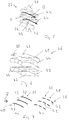
- FIG. 3 shows a heatable by electrical excitation heating element 26, which is provided as a band-like heating conductor element 40, for example, as a metal strip, if necessary, with electrical insulation.
- the heating element 26 or the heating conductor element 40 is provided with a meander-like structure between its two connection regions 30, 32 provided for electrical contacting and thus has a plurality of substantially parallel longitudinal sections 42 which adjoin one another in respective curved regions 44.
- the strip surface O provided substantially by the two broad sides B 1 , B 2 of the heating conductor element 40 facing away from one another is oriented, in particular in the longitudinal sections 42 and in the curved regions 44, such that they, like the Fig. 5 this suggests, is substantially parallel to the flow direction of the exhaust gas A.
- an impairment of the flow of the exhaust gas A is largely avoided, in particular in the region of the occupied by the spray cone of the reagent R volume range V.
- the heating element 40 provided with its meandering structure provides a comparatively large surface area O, upon which the reactant R discharged through the reagent injection assembly 20 can impinge and thus absorb heat.
- the arrangement of the heating conductor element 40 is preferably such that the reaction agent R discharged through the reaction agent injection arrangement 20 has a flow direction component parallel to the surface O, so that it can enter the intermediate spaces formed between the sections 42 and thus impinge on the surface O.
- FIG Fig. 6 An embodiment of the heating element 26 or of the heating conductor element 40 designed differently in particular with respect to the positioning is shown in FIG Fig. 6 shown. It can be seen that in this embodiment, the two terminal portions 30, 32, unlike in the embodiment according to Fig. 3 are not oriented in a common plane and away from each other, but in mutually offset planes and the two last band portions 42 are arranged substantially in a straight line continuing.
- the Fig. 7 illustrates in a schematic representation of various embodiments of the heating assembly 24.
- the representation of Fig. 7a corresponds substantially to the embodiment according to Fig. 3 or Fig. 6 with a heater element 40 which provides the heating element 26 and, in the illustrated example, has three band sections 42 oriented essentially parallel to one another.
- Fig. 7b three such Thompsonieri 40 are provided, which lie substantially in the flow direction of the exhaust gas A consecutively and, for example, each also three mutually substantially parallel oriented longitudinal sections 42 have.
- the successive in the flow direction of the exhaust gas A Schuleiteriata 40 are preferably positioned so that their length sections 42 to reduce the flow resistance for the exhaust gas flowing in the exhaust duct 14 exhaust gas A each other in the flow direction continuing, that are arranged substantially in alignment with each other.
- the heating conductor element 40 has two heating conductor sections 40 ', 40 ", which extend substantially next to one another in the heating conductor section longitudinal direction H L and are respectively meandered, ie provided with a substantially wave-like structure of the respective curvature regions 44 ', 44 "of the heating conductor sections 40', 40", bulges that are oriented away from one another in a direction transverse to the heating conductor section longitudinal direction H L are formed, between which the longitudinal sections 42 ', 42 "extend.
- the two adjacent heating conductor sections 40', 40" each have a connection region 30, 32.
- the two heating conductor sections 40', 40" adjoin one another via a connection region 41 and thus form an integral structure of the heating conductor element 40.
- the two connection regions 30, 32 thus lie directly next to one another and can be easily and simply connected Way with correspondingly shaped counter-connection areas, for example, on an exhaust gas duct, are electrically contacted.
- the surfaces O ', O "of the heating conductor sections 40', 40" formed on respective broad sides B 1 , B 2 are oriented essentially parallel to one another, so that the exhaust gas A flowing around the heating element 40 has a very low flow resistance, while at the same time providing a comparatively high flow resistance large surface for heating the injected into the exhaust gas A reagent R is available.
- bulges of the two heating conductor sections 40 ', 40 "formed in the region of the curved regions 44', 44" in the heating conductor section longitudinal direction H L are also offset relative to one another in this heating conductor element 40, so that essentially there, where in one of the heating conductor sections 40 ', 40 "a bulge is oriented in a first direction transverse to the heating conductor section longitudinal direction H L , in the same longitudinal region of the other heating conductor section a bulge is oriented in a second direction opposite the first direction transverse to the heating conductor section longitudinal direction H L
- Wienleiterabismee 40 ', 40 "thus have a phase-shifted course to each other, wherein the phase shift can be in the range of half the wavelength of the meandering or wave-like structure but can also assume other values.
- heating element 40 may in principle be constructed a structure as shown in FIG. 7b ) is indicated, wherein not individual separately formed Bankleitermaschine, but Bankleiterabroughe a Schuleiterelements in the flow direction of the exhaust gas A follow one another.
- a plurality of such heating conductor elements 40 as in Fig. 7c ), arranged in succession.
- such a plurality of Thompsonleiterabête comprehensive Schuleiterelement can be constructed with more than two Schuleiterab mustarden. For example, three substantially adjacent Bankleiterab mustarde be provided, in which case the two connection areas are not adjacent to each other, but on opposite sides.
- the 8 to 11 show a further alternative embodiment of a Christskarffyan Aunt 24.
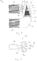
- the Christskaritzan Aunt 24 comprises a trained example as a glow plug heating element 26 which is carried with a body portion 46, for example, the exhaust pipe 12 and with a heatable by electrical excitation heating region or annealing region 48 in the exhaust gas duct 14 sticks out.
- a body portion 46 for example, the exhaust pipe 12
- a heatable by electrical excitation heating region or annealing region 48 in the exhaust gas duct 14 sticks out.
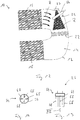
- At this heating area 48 are in the in the Fig. 8 to 10 illustrated example, two plate-like heat transfer elements 50, 52 worn.
- the two heat transfer elements 50, 52 are shaped in such a way that they each form a substantially semicircular formation 54, 56 in their section surrounding the heating region 48, so that a volume region is formed, in which the heating region 48 is below, for example Interim storage of a heat transfer medium 58, such as. As metal powder or graphite foil, is added.
- the two heat transfer elements 50, 52 can be fixed to each other, for example by pressing, welding or the like, and thus be stably supported on the heating area 48.
- exhaust gas passage openings 60 may be formed in the heat transfer elements 50, wherein, for example, adjacent to these exhaust gas passages 60 exhaust guide elements, for example by bending portions of the Heat transfer elements 50, 52 may be provided.
- FIG. 11 An alternative embodiment is in Fig. 11 shown.
- a single plate-like heat transfer element 50 ' is provided with a circular formation 54', which is arranged surrounding the heating element 26 in its heating region 48.
- the heating element 48 may be fixedly connected to the heat transfer element 50, for example by welding 62.
- FIGS Fig. 12 to 14 Another alternative embodiment of a reaction heater 24 is shown in FIGS Fig. 12 to 14 shown.
- the Christsstoffteilan extract 24 includes a heatable by electrical excitation heating element 26, which is formed in this case as a ceramic heating element 64.
- This comprises a carrier 66 fixed, for example, to the exhaust gas guide tube 12, and a plurality of rod-like heating sections 68 extending from the carrier 66 into the volume region V in the example shown. These can be used for efficient thermal interaction with the reagent R in an in Fig. 14 illustrated star-like configuration with respect to each other.
- FIG Fig. 15 Another embodiment of a reaction heater 24 is shown in FIG Fig. 15 shown.
- the Itemssstoffsammlungchristan extract 24 includes a heating element 26, which in terms of its construction substantially in Fig. 9
- the heating element 26 shown can correspond to a heating region 48 that can be heated by electrical excitation and, in particular, in the area of the volume region V can have.
- the heating region 48 is surrounded by a reagent receiving body 70 of porous material.
- the reactant R discharged from the reagent injection assembly 20 impinges on the surface of the porous reactant receiving body 70 and can enter its inside volume portion by capillary action.
- the reagent receiving body 70 thus forms a reagent reservoir in which the reactant is heated and dispensed in vapor form. This leads to a homogenization of the output in the form of vapor in the flow of the exhaust gas A and then mixed by the mixer assembly 22 completely with the exhaust gas A reactant stream.
- the reagent receiving body 70 is preferably made of metal foam material or other porous material, such as. B. wire mesh, constructed.
- an exhaust system may also include several of the above-described Christsschitzan elbow different types in combination.
Landscapes
- Chemical & Material Sciences (AREA)
- Engineering & Computer Science (AREA)
- Chemical Kinetics & Catalysis (AREA)
- Health & Medical Sciences (AREA)
- Toxicology (AREA)
- Combustion & Propulsion (AREA)
- Mechanical Engineering (AREA)
- General Engineering & Computer Science (AREA)
- Exhaust Gas After Treatment (AREA)
Claims (13)
- Système d'échappement, en particulier pour un moteur à combustion interne d'un véhicule, comprenant- un canal de guidage de gaz d'échappement (14),- un arrangement d'injection de réactif (20) pour injecter du réactif (R) dans le gaz d'échappement (A) passant par le canal de guidage de gaz d'échappement (14),- en aval de l'arrangement d'injection de réactif (20) un arrangement de mélangeur (22) pour faciliter le mélange de réactif injecté par l'arrangement d'injection de réactif (20) avec du gaz d'échappement (A) passant par le canal de guidage de gaz d'échappement (14),- en amont de l'arrangement d'injection de réactif (20) et en amont de l'arrangement de mélangeur (22), un arrangement de chauffage de réactif (24) s'étendant dans le canal de guidage de gaz d'échappement (14) autour duquel le flux de gaz d'échappement (A) et le réactif (R) injecté par l'arrangement d'injection de réactif (20) peuvent passer,où l'arrangement de chauffage de réactif (24) comprend au moins un élément de chauffage (26) qui peut être chauffé par une excitation électrique et autour duquel le flux de gaz d'échappement (A) et le réactif (R) peuvent passer,
caractérisé en ce qu'au moins un élément de chauffage (40) en tant qu'élément conducteur de chaleur a une configuration en forme de bande, est adapté en tournant au moins en partie en serpentin et comprend une surface de bande (O) essentiellement parallèle à un sens du flux du gaz d'échappement. - Système d'échappement selon la revendication 1, caractérisé en ce que l'arrangement de chauffage de réactif (24) s'étend dans la région de volume (V) couverte par un cône de pulvérisation formé à l'arrangement d'injection de réactif (20).
- Système d'échappement selon les revendications 1 ou 2, caractérisé en ce qu'au moins un élément conducteur de chaleur (27) forme une boucle conductrice de chaleur fermé (34).
- Système d'échappement selon la revendication 1, 2 ou 3, caractérisé en ce qu'une pluralité d'éléments de chauffage (40) est arrangée se succédant dans le sens du flux de gaz d'échappement.
- Système d'échappement selon une des revendications 1-4, caractérisé en ce que l'arrangement de chauffage de réactif (24) comprend au moins un élément de chauffage (26) qui peut être chauffé par une excitation électrique et au moins un élément de transfert de chaleur (50, 52 ;50') essentiellement en forme de plaque qui est en communication de transfert de chaleur avec l'élément de chauffage (26).
- Système d'échappement selon la revendication 5, caractérisé en ce qu'au moins un élément de transfert de chaleur en forme de plaque (50, 52 ;50') comprend une surface d'élément de transfert de chaleur (OW) essentiellement parallèle à un flux de gaz d'échappement.
- Système d'échappement selon les revendications 5 ou 6, caractérisé en ce qu'au moins un élément de chauffage (26) est supporté entre deux éléments de transfert de chaleur en forme de plaque (50, 52) interconnectés et de préférence au moins en partie en appui.
- Système d'échappement selon une des revendications 5-7, caractérisé en ce qu'un médium de transfert de chaleur (58), de préférence une poudre de métal ou/et un matériau de graphite, est arrangé entre au moins un élément de transfert de chaleur en forme de plaque (50, 52) et un élément de chauffage (26).
- Système d'échappement selon une des revendications 5-7, caractérisé en ce qu'au moins un élément de transfert de chaleur en forme de plaque (50, 52 ;50') comprend une pluralité d'ouvertures de passage de gaz d'échappement (60) ou/et d'éléments de guidage de gaz d'échappement.
- Système d'échappement selon une des revendications 1-9, caractérisé en ce que l'arrangement de chauffage de réactif (24) comprend au moins un élément de chauffage en céramique (64) qui peut être chauffé par excitation électrique.
- Système d'échappement selon la revendication 10, caractérisé en ce qu'au moins un élément de chauffage en céramique (64) comprend une pluralité de sections de chauffage en forme de barre (68).
- Système d'échappement selon une des revendications 1-11, caractérisé en ce que l'arrangement de chauffage de réactif (24) comprend au moins un élément de chauffage (26) qui peut être chauffé par excitation électrique et un corps de réception de réactif (70) poreux entourant l'élément de chauffage (26) au moins en partie, de préférence fait d'un matériau de mousse métallique ou d'un treillis métallique.
- Système d'échappement selon une des revendications 1-12, caractérisé en ce qu'un arrangement de traitement à réactif (18), de préférence un arrangement de catalyseur pour la réaction catalytique sélective ou/et un filtre à particules, est arrangé en aval de l'arrangement de mélangeur (22).
Applications Claiming Priority (2)
| Application Number | Priority Date | Filing Date | Title |
|---|---|---|---|
| DE102016103798 | 2016-03-03 | ||
| DE102016107213.3A DE102016107213A1 (de) | 2016-03-03 | 2016-04-19 | Abgasanlage, insbesondere für eine Brennkraftmaschine eines Fahrzeugs |
Publications (3)
| Publication Number | Publication Date |
|---|---|
| EP3214284A2 EP3214284A2 (fr) | 2017-09-06 |
| EP3214284A3 EP3214284A3 (fr) | 2017-11-15 |
| EP3214284B1 true EP3214284B1 (fr) | 2019-03-13 |
Family
ID=57708503
Family Applications (1)
| Application Number | Title | Priority Date | Filing Date |
|---|---|---|---|
| EP17150122.4A Active EP3214284B1 (fr) | 2016-03-03 | 2017-01-03 | Système d'échappement en particulier pour un moteur à combustion interne d'un véhicule automobile |
Country Status (1)
| Country | Link |
|---|---|
| EP (1) | EP3214284B1 (fr) |
Families Citing this family (3)
| Publication number | Priority date | Publication date | Assignee | Title |
|---|---|---|---|---|
| WO2017151975A1 (fr) | 2016-03-02 | 2017-09-08 | Watlow Electric Manufacturing Company | Éléments de chauffage à nu pour le chauffage d'écoulements de fluide |
| DE102020110869A1 (de) * | 2020-04-22 | 2021-10-28 | Purem GmbH | Abgasheizer |
| JP2024546757A (ja) * | 2021-12-09 | 2024-12-26 | エミッソル リミテッド ライアビリティー カンパニー | 排ガス混合器、システム、及び使用方法 |
Citations (1)
| Publication number | Priority date | Publication date | Assignee | Title |
|---|---|---|---|---|
| DE10223148A1 (de) * | 2002-05-16 | 2003-11-27 | Ego Elektro Geraetebau Gmbh | Partikelfilter mit einer elektrischen Heizung |
Family Cites Families (12)
| Publication number | Priority date | Publication date | Assignee | Title |
|---|---|---|---|---|
| US4671058A (en) * | 1983-11-21 | 1987-06-09 | Nippondenso Co., Ltd. | Heating device |
| JPS61163585A (ja) * | 1985-01-11 | 1986-07-24 | 株式会社デンソー | セラミツクヒ−タ |
| JPH05296032A (ja) * | 1992-04-21 | 1993-11-09 | Ngk Spark Plug Co Ltd | 電気ヒータ |
| US6722123B2 (en) * | 2001-10-17 | 2004-04-20 | Fleetguard, Inc. | Exhaust aftertreatment device, including chemical mixing and acoustic effects |
| KR100534081B1 (ko) * | 2003-06-12 | 2005-12-07 | 일진전기 주식회사 | 지그를 이용한 전기히터 제작방법 및 그 전기히터 |
| US8935918B2 (en) * | 2010-04-23 | 2015-01-20 | GM Global Technology Operations LLC | Reconfigurable mixer for an exhaust aftertreatment system and method of using the same |
| US20110271662A1 (en) * | 2010-05-10 | 2011-11-10 | Winsor Richard E | Compact reduction agent doser for use in an scr system of an internal combustion engine |
| DE102011088569A1 (de) * | 2011-12-14 | 2013-06-20 | Robert Bosch Gmbh | Vorrichtung und Verfahren zum Verdampfen eines Fluids in einem Abgasstrang |
| DE202012011764U1 (de) * | 2012-12-07 | 2013-03-21 | Eberspächer Catem Gmbh & Co. Kg | Mischer zur Nachbehandlung von Abgasen |
| FR3014136B1 (fr) * | 2013-12-03 | 2018-04-20 | Faurecia Systemes D'echappement | Dispositif d'injection d'un reducteur et ligne d'echappement correspondante |
| JP6083374B2 (ja) | 2013-12-05 | 2017-02-22 | 株式会社デンソー | 還元剤添加装置 |
| DE102014111310B4 (de) * | 2014-08-07 | 2021-05-06 | Denso Corporation | Abgasmischer mit integrierter Heizeinrichtung |
-
2017
- 2017-01-03 EP EP17150122.4A patent/EP3214284B1/fr active Active
Patent Citations (1)
| Publication number | Priority date | Publication date | Assignee | Title |
|---|---|---|---|---|
| DE10223148A1 (de) * | 2002-05-16 | 2003-11-27 | Ego Elektro Geraetebau Gmbh | Partikelfilter mit einer elektrischen Heizung |
Also Published As
| Publication number | Publication date |
|---|---|
| EP3214284A3 (fr) | 2017-11-15 |
| EP3214284A2 (fr) | 2017-09-06 |
Similar Documents
| Publication | Publication Date | Title |
|---|---|---|
| DE102016107213A1 (de) | Abgasanlage, insbesondere für eine Brennkraftmaschine eines Fahrzeugs | |
| EP3473827B1 (fr) | Dispositif de mélange | |
| EP4023864B1 (fr) | Unité électrique de chauffage pour gaz d'échappement | |
| EP2929156B1 (fr) | Mélangeur pour le traitement de gaz d'échappement | |
| EP0412086B1 (fr) | Dispositif pour accelerer la reponse d'un catalyseur de gaz d'echappement | |
| EP2836687B1 (fr) | Connection électrique de plusieurs couches en tôle d'un corps en nid d'abeille et corps en nid d'abeille correspondant | |
| EP3686405B1 (fr) | Élément chauffant de gaz d'échappement | |
| EP0605479B1 (fr) | Pot catalytique | |
| DE112020002424T5 (de) | Fahrzeugabgasreinigungsvorrichtung, entsprechendes Herstellungsverfahren, Abgasleitung und Fahrzeug | |
| EP0845074B1 (fr) | Catalyseur pour la reduction des hydrocarbures dans les gaz d'echappement d'un vehicule a moteur | |
| EP3584003B1 (fr) | Mélangeur | |
| EP3212907A1 (fr) | Corps en nid-d'abeilles à dispositif de chauffe électrique | |
| EP3470640B1 (fr) | Module de traitement de gaz d'échappement | |
| EP4174294B1 (fr) | Unité de chauffage pour un système d'échappement d'un moteur à combustion interne | |
| EP2061580B1 (fr) | Dispositif d'évaporation d'un réactif | |
| EP3545179B1 (fr) | Dispositif d'évaporation d'un fluide | |
| DE102014117687A1 (de) | Vorrichtung zum Einspritzen eines Reduktionsmittels und entsprechender Abgasstrang | |
| DE102007002981B4 (de) | Statischer Mischer für eine Abgasanlage eines brennkraftmaschinenbetriebenen Fahrzeugs, insbesondere Kraftfahrzeugs | |
| EP3214284A2 (fr) | Système d'échappement en particulier pour un moteur à combustion interne d'un véhicule automobile | |
| EP3943720A1 (fr) | Dispositif de chauffage électrique | |
| EP3321484B1 (fr) | Dispositif de distribution d'agent réactif | |
| DE102022132126A1 (de) | Abgasbehandlungsanordnung | |
| DE102022103212A1 (de) | Heizelement und Abgasstrang mit einem derartigen Element | |
| EP3990760A1 (fr) | Dispositif de post-traitement de gaz d'échappement | |
| DE10009938B4 (de) | Vorrichtung zum Reinigen von Abgas |
Legal Events
| Date | Code | Title | Description |
|---|---|---|---|
| PUAI | Public reference made under article 153(3) epc to a published international application that has entered the european phase |
Free format text: ORIGINAL CODE: 0009012 |
|
| STAA | Information on the status of an ep patent application or granted ep patent |
Free format text: STATUS: THE APPLICATION HAS BEEN PUBLISHED |
|
| AK | Designated contracting states |
Kind code of ref document: A2 Designated state(s): AL AT BE BG CH CY CZ DE DK EE ES FI FR GB GR HR HU IE IS IT LI LT LU LV MC MK MT NL NO PL PT RO RS SE SI SK SM TR |
|
| AX | Request for extension of the european patent |
Extension state: BA ME |
|
| PUAL | Search report despatched |
Free format text: ORIGINAL CODE: 0009013 |
|
| AK | Designated contracting states |
Kind code of ref document: A3 Designated state(s): AL AT BE BG CH CY CZ DE DK EE ES FI FR GB GR HR HU IE IS IT LI LT LU LV MC MK MT NL NO PL PT RO RS SE SI SK SM TR |
|
| AX | Request for extension of the european patent |
Extension state: BA ME |
|
| RIC1 | Information provided on ipc code assigned before grant |
Ipc: H05B 3/20 20060101ALI20171010BHEP Ipc: F01N 3/20 20060101AFI20171010BHEP Ipc: F01N 3/28 20060101ALI20171010BHEP |
|
| STAA | Information on the status of an ep patent application or granted ep patent |
Free format text: STATUS: REQUEST FOR EXAMINATION WAS MADE |
|
| 17P | Request for examination filed |
Effective date: 20180306 |
|
| RBV | Designated contracting states (corrected) |
Designated state(s): AL AT BE BG CH CY CZ DE DK EE ES FI FR GB GR HR HU IE IS IT LI LT LU LV MC MK MT NL NO PL PT RO RS SE SI SK SM TR |
|
| GRAP | Despatch of communication of intention to grant a patent |
Free format text: ORIGINAL CODE: EPIDOSNIGR1 |
|
| STAA | Information on the status of an ep patent application or granted ep patent |
Free format text: STATUS: GRANT OF PATENT IS INTENDED |
|
| INTG | Intention to grant announced |
Effective date: 20181010 |
|
| GRAS | Grant fee paid |
Free format text: ORIGINAL CODE: EPIDOSNIGR3 |
|
| GRAA | (expected) grant |
Free format text: ORIGINAL CODE: 0009210 |
|
| STAA | Information on the status of an ep patent application or granted ep patent |
Free format text: STATUS: THE PATENT HAS BEEN GRANTED |
|
| AK | Designated contracting states |
Kind code of ref document: B1 Designated state(s): AL AT BE BG CH CY CZ DE DK EE ES FI FR GB GR HR HU IE IS IT LI LT LU LV MC MK MT NL NO PL PT RO RS SE SI SK SM TR |
|
| REG | Reference to a national code |
Ref country code: GB Ref legal event code: FG4D Free format text: NOT ENGLISH |
|
| REG | Reference to a national code |
Ref country code: AT Ref legal event code: REF Ref document number: 1107977 Country of ref document: AT Kind code of ref document: T Effective date: 20190315 Ref country code: CH Ref legal event code: EP |
|
| REG | Reference to a national code |
Ref country code: IE Ref legal event code: FG4D Free format text: LANGUAGE OF EP DOCUMENT: GERMAN |
|
| REG | Reference to a national code |
Ref country code: DE Ref legal event code: R096 Ref document number: 502017000898 Country of ref document: DE |
|
| REG | Reference to a national code |
Ref country code: SE Ref legal event code: TRGR |
|
| REG | Reference to a national code |
Ref country code: NL Ref legal event code: MP Effective date: 20190313 |
|
| REG | Reference to a national code |
Ref country code: LT Ref legal event code: MG4D |
|
| PG25 | Lapsed in a contracting state [announced via postgrant information from national office to epo] |
Ref country code: LT Free format text: LAPSE BECAUSE OF FAILURE TO SUBMIT A TRANSLATION OF THE DESCRIPTION OR TO PAY THE FEE WITHIN THE PRESCRIBED TIME-LIMIT Effective date: 20190313 Ref country code: NO Free format text: LAPSE BECAUSE OF FAILURE TO SUBMIT A TRANSLATION OF THE DESCRIPTION OR TO PAY THE FEE WITHIN THE PRESCRIBED TIME-LIMIT Effective date: 20190613 Ref country code: FI Free format text: LAPSE BECAUSE OF FAILURE TO SUBMIT A TRANSLATION OF THE DESCRIPTION OR TO PAY THE FEE WITHIN THE PRESCRIBED TIME-LIMIT Effective date: 20190313 |
|
| PG25 | Lapsed in a contracting state [announced via postgrant information from national office to epo] |
Ref country code: HR Free format text: LAPSE BECAUSE OF FAILURE TO SUBMIT A TRANSLATION OF THE DESCRIPTION OR TO PAY THE FEE WITHIN THE PRESCRIBED TIME-LIMIT Effective date: 20190313 Ref country code: GR Free format text: LAPSE BECAUSE OF FAILURE TO SUBMIT A TRANSLATION OF THE DESCRIPTION OR TO PAY THE FEE WITHIN THE PRESCRIBED TIME-LIMIT Effective date: 20190614 Ref country code: BG Free format text: LAPSE BECAUSE OF FAILURE TO SUBMIT A TRANSLATION OF THE DESCRIPTION OR TO PAY THE FEE WITHIN THE PRESCRIBED TIME-LIMIT Effective date: 20190613 Ref country code: RS Free format text: LAPSE BECAUSE OF FAILURE TO SUBMIT A TRANSLATION OF THE DESCRIPTION OR TO PAY THE FEE WITHIN THE PRESCRIBED TIME-LIMIT Effective date: 20190313 Ref country code: LV Free format text: LAPSE BECAUSE OF FAILURE TO SUBMIT A TRANSLATION OF THE DESCRIPTION OR TO PAY THE FEE WITHIN THE PRESCRIBED TIME-LIMIT Effective date: 20190313 Ref country code: NL Free format text: LAPSE BECAUSE OF FAILURE TO SUBMIT A TRANSLATION OF THE DESCRIPTION OR TO PAY THE FEE WITHIN THE PRESCRIBED TIME-LIMIT Effective date: 20190313 |
|
| PG25 | Lapsed in a contracting state [announced via postgrant information from national office to epo] |
Ref country code: EE Free format text: LAPSE BECAUSE OF FAILURE TO SUBMIT A TRANSLATION OF THE DESCRIPTION OR TO PAY THE FEE WITHIN THE PRESCRIBED TIME-LIMIT Effective date: 20190313 Ref country code: CZ Free format text: LAPSE BECAUSE OF FAILURE TO SUBMIT A TRANSLATION OF THE DESCRIPTION OR TO PAY THE FEE WITHIN THE PRESCRIBED TIME-LIMIT Effective date: 20190313 Ref country code: RO Free format text: LAPSE BECAUSE OF FAILURE TO SUBMIT A TRANSLATION OF THE DESCRIPTION OR TO PAY THE FEE WITHIN THE PRESCRIBED TIME-LIMIT Effective date: 20190313 Ref country code: IT Free format text: LAPSE BECAUSE OF FAILURE TO SUBMIT A TRANSLATION OF THE DESCRIPTION OR TO PAY THE FEE WITHIN THE PRESCRIBED TIME-LIMIT Effective date: 20190313 Ref country code: SK Free format text: LAPSE BECAUSE OF FAILURE TO SUBMIT A TRANSLATION OF THE DESCRIPTION OR TO PAY THE FEE WITHIN THE PRESCRIBED TIME-LIMIT Effective date: 20190313 Ref country code: PT Free format text: LAPSE BECAUSE OF FAILURE TO SUBMIT A TRANSLATION OF THE DESCRIPTION OR TO PAY THE FEE WITHIN THE PRESCRIBED TIME-LIMIT Effective date: 20190713 Ref country code: AL Free format text: LAPSE BECAUSE OF FAILURE TO SUBMIT A TRANSLATION OF THE DESCRIPTION OR TO PAY THE FEE WITHIN THE PRESCRIBED TIME-LIMIT Effective date: 20190313 Ref country code: ES Free format text: LAPSE BECAUSE OF FAILURE TO SUBMIT A TRANSLATION OF THE DESCRIPTION OR TO PAY THE FEE WITHIN THE PRESCRIBED TIME-LIMIT Effective date: 20190313 |
|
| PG25 | Lapsed in a contracting state [announced via postgrant information from national office to epo] |
Ref country code: PL Free format text: LAPSE BECAUSE OF FAILURE TO SUBMIT A TRANSLATION OF THE DESCRIPTION OR TO PAY THE FEE WITHIN THE PRESCRIBED TIME-LIMIT Effective date: 20190313 Ref country code: SM Free format text: LAPSE BECAUSE OF FAILURE TO SUBMIT A TRANSLATION OF THE DESCRIPTION OR TO PAY THE FEE WITHIN THE PRESCRIBED TIME-LIMIT Effective date: 20190313 |
|
| REG | Reference to a national code |
Ref country code: DE Ref legal event code: R097 Ref document number: 502017000898 Country of ref document: DE |
|
| PG25 | Lapsed in a contracting state [announced via postgrant information from national office to epo] |
Ref country code: IS Free format text: LAPSE BECAUSE OF FAILURE TO SUBMIT A TRANSLATION OF THE DESCRIPTION OR TO PAY THE FEE WITHIN THE PRESCRIBED TIME-LIMIT Effective date: 20190713 |
|
| PLBE | No opposition filed within time limit |
Free format text: ORIGINAL CODE: 0009261 |
|
| STAA | Information on the status of an ep patent application or granted ep patent |
Free format text: STATUS: NO OPPOSITION FILED WITHIN TIME LIMIT |
|
| PG25 | Lapsed in a contracting state [announced via postgrant information from national office to epo] |
Ref country code: DK Free format text: LAPSE BECAUSE OF FAILURE TO SUBMIT A TRANSLATION OF THE DESCRIPTION OR TO PAY THE FEE WITHIN THE PRESCRIBED TIME-LIMIT Effective date: 20190313 |
|
| 26N | No opposition filed |
Effective date: 20191216 |
|
| PG25 | Lapsed in a contracting state [announced via postgrant information from national office to epo] |
Ref country code: SI Free format text: LAPSE BECAUSE OF FAILURE TO SUBMIT A TRANSLATION OF THE DESCRIPTION OR TO PAY THE FEE WITHIN THE PRESCRIBED TIME-LIMIT Effective date: 20190313 |
|
| PG25 | Lapsed in a contracting state [announced via postgrant information from national office to epo] |
Ref country code: TR Free format text: LAPSE BECAUSE OF FAILURE TO SUBMIT A TRANSLATION OF THE DESCRIPTION OR TO PAY THE FEE WITHIN THE PRESCRIBED TIME-LIMIT Effective date: 20190313 |
|
| PG25 | Lapsed in a contracting state [announced via postgrant information from national office to epo] |
Ref country code: MC Free format text: LAPSE BECAUSE OF FAILURE TO SUBMIT A TRANSLATION OF THE DESCRIPTION OR TO PAY THE FEE WITHIN THE PRESCRIBED TIME-LIMIT Effective date: 20190313 |
|
| REG | Reference to a national code |
Ref country code: CH Ref legal event code: PL |
|
| REG | Reference to a national code |
Ref country code: BE Ref legal event code: MM Effective date: 20200131 |
|
| PG25 | Lapsed in a contracting state [announced via postgrant information from national office to epo] |
Ref country code: LU Free format text: LAPSE BECAUSE OF NON-PAYMENT OF DUE FEES Effective date: 20200103 |
|
| PG25 | Lapsed in a contracting state [announced via postgrant information from national office to epo] |
Ref country code: CH Free format text: LAPSE BECAUSE OF NON-PAYMENT OF DUE FEES Effective date: 20200131 Ref country code: LI Free format text: LAPSE BECAUSE OF NON-PAYMENT OF DUE FEES Effective date: 20200131 Ref country code: BE Free format text: LAPSE BECAUSE OF NON-PAYMENT OF DUE FEES Effective date: 20200131 |
|
| PG25 | Lapsed in a contracting state [announced via postgrant information from national office to epo] |
Ref country code: IE Free format text: LAPSE BECAUSE OF NON-PAYMENT OF DUE FEES Effective date: 20200103 |
|
| REG | Reference to a national code |
Ref country code: DE Ref legal event code: R082 Ref document number: 502017000898 Country of ref document: DE Representative=s name: RUTTENSPERGER LACHNIT TROSSIN GOMOLL, PATENT- , DE Ref country code: DE Ref legal event code: R081 Ref document number: 502017000898 Country of ref document: DE Owner name: PUREM GMBH, DE Free format text: FORMER OWNER: EBERSPAECHER EXHAUST TECHNOLOGY GMBH & CO. KG, 66539 NEUNKIRCHEN, DE |
|
| REG | Reference to a national code |
Ref country code: GB Ref legal event code: 732E Free format text: REGISTERED BETWEEN 20210902 AND 20210908 |
|
| PG25 | Lapsed in a contracting state [announced via postgrant information from national office to epo] |
Ref country code: MT Free format text: LAPSE BECAUSE OF FAILURE TO SUBMIT A TRANSLATION OF THE DESCRIPTION OR TO PAY THE FEE WITHIN THE PRESCRIBED TIME-LIMIT Effective date: 20190313 Ref country code: CY Free format text: LAPSE BECAUSE OF FAILURE TO SUBMIT A TRANSLATION OF THE DESCRIPTION OR TO PAY THE FEE WITHIN THE PRESCRIBED TIME-LIMIT Effective date: 20190313 |
|
| PG25 | Lapsed in a contracting state [announced via postgrant information from national office to epo] |
Ref country code: MK Free format text: LAPSE BECAUSE OF FAILURE TO SUBMIT A TRANSLATION OF THE DESCRIPTION OR TO PAY THE FEE WITHIN THE PRESCRIBED TIME-LIMIT Effective date: 20190313 |
|
| REG | Reference to a national code |
Ref country code: AT Ref legal event code: MM01 Ref document number: 1107977 Country of ref document: AT Kind code of ref document: T Effective date: 20220103 |
|
| PG25 | Lapsed in a contracting state [announced via postgrant information from national office to epo] |
Ref country code: AT Free format text: LAPSE BECAUSE OF NON-PAYMENT OF DUE FEES Effective date: 20220103 |
|
| PGFP | Annual fee paid to national office [announced via postgrant information from national office to epo] |
Ref country code: SE Payment date: 20230123 Year of fee payment: 7 |
|
| REG | Reference to a national code |
Ref country code: SE Ref legal event code: EUG |
|
| PG25 | Lapsed in a contracting state [announced via postgrant information from national office to epo] |
Ref country code: SE Free format text: LAPSE BECAUSE OF NON-PAYMENT OF DUE FEES Effective date: 20240104 |
|
| PGFP | Annual fee paid to national office [announced via postgrant information from national office to epo] |
Ref country code: GB Payment date: 20260122 Year of fee payment: 10 |
|
| PGFP | Annual fee paid to national office [announced via postgrant information from national office to epo] |
Ref country code: DE Payment date: 20260120 Year of fee payment: 10 |
|
| PGFP | Annual fee paid to national office [announced via postgrant information from national office to epo] |
Ref country code: FR Payment date: 20260121 Year of fee payment: 10 |