EP3214310A1 - Rotoranordnung für eine pumpe sowie pumpenaggregat - Google Patents
Rotoranordnung für eine pumpe sowie pumpenaggregat Download PDFInfo
- Publication number
- EP3214310A1 EP3214310A1 EP17158319.8A EP17158319A EP3214310A1 EP 3214310 A1 EP3214310 A1 EP 3214310A1 EP 17158319 A EP17158319 A EP 17158319A EP 3214310 A1 EP3214310 A1 EP 3214310A1
- Authority
- EP
- European Patent Office
- Prior art keywords
- axial
- drive shaft
- rotor
- section
- pump
- Prior art date
- Legal status (The legal status is an assumption and is not a legal conclusion. Google has not performed a legal analysis and makes no representation as to the accuracy of the status listed.)
- Withdrawn
Links
- 238000003780 insertion Methods 0.000 claims description 3
- 230000037431 insertion Effects 0.000 claims description 3
- 230000004323 axial length Effects 0.000 description 17
- 238000005096 rolling process Methods 0.000 description 3
- 238000005452 bending Methods 0.000 description 2
- 239000012530 fluid Substances 0.000 description 2
- 230000007704 transition Effects 0.000 description 2
- 230000005540 biological transmission Effects 0.000 description 1
- 238000011161 development Methods 0.000 description 1
- 230000018109 developmental process Effects 0.000 description 1
- 238000006073 displacement reaction Methods 0.000 description 1
- 239000007788 liquid Substances 0.000 description 1
- 230000002093 peripheral effect Effects 0.000 description 1
Images

Classifications
-
- F—MECHANICAL ENGINEERING; LIGHTING; HEATING; WEAPONS; BLASTING
- F04—POSITIVE - DISPLACEMENT MACHINES FOR LIQUIDS; PUMPS FOR LIQUIDS OR ELASTIC FLUIDS
- F04C—ROTARY-PISTON, OR OSCILLATING-PISTON, POSITIVE-DISPLACEMENT MACHINES FOR LIQUIDS; ROTARY-PISTON, OR OSCILLATING-PISTON, POSITIVE-DISPLACEMENT PUMPS
- F04C2/00—Rotary-piston machines or pumps
- F04C2/08—Rotary-piston machines or pumps of intermeshing-engagement type, i.e. with engagement of co-operating members similar to that of toothed gearing
- F04C2/10—Rotary-piston machines or pumps of intermeshing-engagement type, i.e. with engagement of co-operating members similar to that of toothed gearing of internal-axis type with the outer member having more teeth or tooth-equivalents, e.g. rollers, than the inner member
- F04C2/102—Rotary-piston machines or pumps of intermeshing-engagement type, i.e. with engagement of co-operating members similar to that of toothed gearing of internal-axis type with the outer member having more teeth or tooth-equivalents, e.g. rollers, than the inner member the two members rotating simultaneously around their respective axes
-
- F—MECHANICAL ENGINEERING; LIGHTING; HEATING; WEAPONS; BLASTING
- F04—POSITIVE - DISPLACEMENT MACHINES FOR LIQUIDS; PUMPS FOR LIQUIDS OR ELASTIC FLUIDS
- F04C—ROTARY-PISTON, OR OSCILLATING-PISTON, POSITIVE-DISPLACEMENT MACHINES FOR LIQUIDS; ROTARY-PISTON, OR OSCILLATING-PISTON, POSITIVE-DISPLACEMENT PUMPS
- F04C15/00—Component parts, details or accessories of machines, pumps or pumping installations, not provided for in groups F04C2/00 - F04C14/00
- F04C15/0057—Driving elements, brakes, couplings, transmission specially adapted for machines or pumps
- F04C15/0076—Fixing rotors on shafts, e.g. by clamping together hub and shaft
-
- F—MECHANICAL ENGINEERING; LIGHTING; HEATING; WEAPONS; BLASTING
- F04—POSITIVE - DISPLACEMENT MACHINES FOR LIQUIDS; PUMPS FOR LIQUIDS OR ELASTIC FLUIDS
- F04C—ROTARY-PISTON, OR OSCILLATING-PISTON, POSITIVE-DISPLACEMENT MACHINES FOR LIQUIDS; ROTARY-PISTON, OR OSCILLATING-PISTON, POSITIVE-DISPLACEMENT PUMPS
- F04C2230/00—Manufacture
- F04C2230/60—Assembly methods
- F04C2230/602—Gap; Clearance
-
- F—MECHANICAL ENGINEERING; LIGHTING; HEATING; WEAPONS; BLASTING
- F04—POSITIVE - DISPLACEMENT MACHINES FOR LIQUIDS; PUMPS FOR LIQUIDS OR ELASTIC FLUIDS
- F04C—ROTARY-PISTON, OR OSCILLATING-PISTON, POSITIVE-DISPLACEMENT MACHINES FOR LIQUIDS; ROTARY-PISTON, OR OSCILLATING-PISTON, POSITIVE-DISPLACEMENT PUMPS
- F04C2230/00—Manufacture
- F04C2230/60—Assembly methods
- F04C2230/603—Centering; Aligning
-
- F—MECHANICAL ENGINEERING; LIGHTING; HEATING; WEAPONS; BLASTING
- F04—POSITIVE - DISPLACEMENT MACHINES FOR LIQUIDS; PUMPS FOR LIQUIDS OR ELASTIC FLUIDS
- F04C—ROTARY-PISTON, OR OSCILLATING-PISTON, POSITIVE-DISPLACEMENT MACHINES FOR LIQUIDS; ROTARY-PISTON, OR OSCILLATING-PISTON, POSITIVE-DISPLACEMENT PUMPS
- F04C2240/00—Components
- F04C2240/20—Rotors
-
- F—MECHANICAL ENGINEERING; LIGHTING; HEATING; WEAPONS; BLASTING
- F04—POSITIVE - DISPLACEMENT MACHINES FOR LIQUIDS; PUMPS FOR LIQUIDS OR ELASTIC FLUIDS
- F04C—ROTARY-PISTON, OR OSCILLATING-PISTON, POSITIVE-DISPLACEMENT MACHINES FOR LIQUIDS; ROTARY-PISTON, OR OSCILLATING-PISTON, POSITIVE-DISPLACEMENT PUMPS
- F04C2240/00—Components
- F04C2240/60—Shafts
Definitions
- the present invention initially relates to a rotor assembly for a pump, for example for a ring gear machine in a pump unit. Furthermore, the invention relates to a pump unit, which comprises the rotor assembly according to the invention.
- gear pumps are known in which a gear pump is designed for conveying a medium.
- Such gear pumps are designed for example as a toothed ring machine, which is also referred to as a gerotor.
- An inner toothed ring forms a rotor of the pump, on which acts as a result of the generated pressure, a transverse force, which must be counteracted by a corresponding storage. If this lateral force can not be compensated sufficiently, there will be a displacement of the rotor, which in particular can negatively affect the running properties.
- the JP 2012-026294 A shows a fluid pump with a ring gear machine whose inner ring is mounted on a drive shaft and on a housing formed on a stub axle.
- the JP 2015-048784 A teaches an electric oil pump with a ring gear machine.
- a drive shaft of the oil pump is supported at an axial end of the drive shaft in a housing.
- an electric oil pump in which a housing has a bearing portion for supporting a tip end portion of a shaft to supplementally support the shaft.
- the EP 1 580 431 A1 , the JP 2015-108306 A and the EP 2 570 672 A2 show gear pumps in which an outer ring gear is supported by a sliding bearing.
- the object of the present invention is to minimize the undesirable influence of a transverse force on the rotor of a pump with little effort.
- the rotor assembly according to the invention is provided for a pump for conveying a medium.
- the pump preferably forms a pump unit together with an electric motor.
- the rotor assembly comprises a rotor which serves by rotation for the direct delivery of the medium and thus forms a pump rotor.
- the design of the rotor is to be selected according to the applied principle of the pump. If the pump is formed, for example, by a gear pump, then the rotor is a gear or a toothed ring.
- the medium is preferably a liquid, more preferably an oil.
- the rotor has an opening with which it sits non-rotatably on a drive shaft, so that a rotation of the drive shaft leads to a rotation of the rotor.
- a torque from the drive shaft to the rotor is transferable.
- the drive shaft protrudes at least into the opening or preferably through it.
- the opening forms an axis of rotation of the rotor.
- the opening constitutes a hub of the rotor and is preferably continuous.
- the drive shaft forms a component of the rotor assembly.
- the rotor in an operating state at an axial position of the drive shaft relative to the drive shaft about any axis perpendicular to the drive shaft tiltable, d. H. tiltable.
- the said axis of tiltability intersects the drive shaft in said axial position of the drive shaft.
- the said axis of tiltability has an arbitrary angle of rotation with respect to the drive shaft, so that the tiltability of the rotor is independent of the rotational angle of the drive shaft.
- the operating condition is a condition in which the rotor is fully mounted on the drive shaft so that the rotor is non-rotatably mounted on the drive shaft and the rotor assembly is usable for its function in the pump.
- the rotor can be tilted at said axial position about each axis perpendicular to the drive shaft yielding the lateral force, the rotor can follow an occurring lateral force without tilting with respect to the axis of rotation.
- the lateral force yielding drive shaft is then no longer exactly in the axis of rotation.
- the rotor due to its tiltability relative to the drive shaft can remain in the axis of rotation, its function in the pump is not limited. In particular, it does not happen that the rotor rotates in the event of tilting with respect to the axis of rotation with increased friction compared to other stationary or rotating components of the pump. Rather, the rotor shifts parallel to its main extension plane.
- a particular advantage of the rotor assembly according to the invention is that by a low-cost warranty of said tiltability storage of the drive shaft and the rotor is not necessary on both sides of the rotor. It only requires a bearing on one side of the rotor, since it is the rotor according to the invention allows to tilt against the lateral force yielding drive shaft.
- the tiltability of the rotor relative to the drive shaft is limited, so that the rotor can be tilted up to a maximum tilt angle relative to the drive shaft.
- the maximum tilt angle is preferably so large that a maximum occurring during operation of the rotor assembly bending of the drive shaft can be compensated so that the rotor does not tilt with respect to the axis of rotation.
- the maximum tilt angle is preferably at most 5 ° and more preferably at most 1 °.
- the maximum tilt angle is preferably at least 0.1 ° and more preferably at least 0.5 °.
- the opening preferably has a first axial section, which also forms a first axial section of the drive shaft.
- a gap extending around the drive shaft is formed in the opening of the rotor between the rotor and the drive shaft, which constitutes a play in the radial direction between the rotor and the drive shaft.
- the circumferential gap is increasingly formed in the axial direction.
- the radially extending size of the gap i. H. the gap width in the axial direction too.
- Said radial direction is related to the axis of rotation; ie that the radial direction perpendicular to Is rotational axis, namely in the direction of the radii, starting from the axis of rotation.
- Said axial direction is the direction of the axis of rotation.
- the first axial section preferably comprises at least half of the axial length of the opening, but may also comprise the entire axial length of the opening.
- the drive shaft has a convex longitudinal section in an axial region carrying the rotor, in particular in the first axial section.
- the longitudinal section lies in a plane in which the axis of rotation is located.
- the convexity is formed with respect to the shaft bearing surface in the opening of the rotor and allows the tilting of the rotor relative to the drive shaft.
- the rotor has a convex longitudinal section in the region of its opening, in particular in the first axial section of its opening.
- the longitudinal section lies in a plane in which the axis of rotation is located.
- the convexity is formed with respect to the drive shaft and allows the tilting of the rotor relative to the drive shaft.
- the opening preferably further has a second axial section, which also forms a second axial section of the drive shaft.
- the opening has a non-circular cross-section, to which the drive shaft has a corresponding cross-section, so that the rotor sits in the second axial section in a form-fitting manner on the drive shaft and torque can be transmitted from the drive shaft to the rotor.
- the cross section is in one Plane which is perpendicular to the drive shaft or perpendicular to the opening.
- the non-circular cross section of the opening or the corresponding cross section of the drive shaft is preferably formed by a polygonal or by a single or multiple flat.
- the polygon is preferably formed by a square.
- the multiple flat is preferably formed by a two-flat.
- a game is present, which is preferably between 0.05 mm and 0.5 mm.
- the drive shaft preferably further comprises an axial motor portion, in which the drive shaft forms a component of an electric motor for driving the pump; in particular a motor shaft of a motor rotor.
- the axial motor portion is axially spaced from the first axial portion and the second axial portion.
- the axial motor portion is axially spaced from the rotor of the pump and the opening thereof.
- a torque is generated and transmitted to the drive shaft.
- the torque is transmitted further from the drive shaft to the rotor of the pump.
- the first axial section of the drive shaft is preferably arranged axially between the second axial section and the axial motor section.
- the second axial section of the drive shaft is preferably formed on one of the two axial ends of the drive shaft.
- the drive shaft protrudes with its axial end preferably completely into the opening of the rotor. It can protrude with an axial clearance through the opening of the rotor.
- the opening and the drive shaft preferably each have a circular cross section.
- the cross section lies in a plane which is perpendicular to the drive shaft or perpendicular to the opening.
- the first axial section is preferably divided into a first axial section and into a second axial section.
- the gap width is constant in the two axial sections in the axial direction, but differs between the two axial sections, so that the circumferential gap in the axial direction is increasingly formed.
- a step of the gap is formed between the two axial sections.
- the stepped gap can be given by the fact that the opening in the rotor has different diameters in the two axial sections and / or that the drive shaft has different diameters in the two axial sections.
- the circumferential gap preferably has the shape of a hollow cylinder in the two axial sections.
- the opening in the rotor preferably has the shape of a cylinder in the first axial section.
- the opening in the two axial sections preferably has the shape of a cylinder.
- the drive shaft preferably has the shape of a cylinder in the first axial section.
- the drive shaft in the two axial sections has different diameters, so has the drive shaft in the two Axial sections preferably each have the shape of a cylinder.
- the second axial section is preferably arranged between the first axial section and the second axial section.
- the second axial section is located in a central axial region of the opening.
- the second axial portion is located in an axial center of the opening.
- the circumferential gap in the second axial section has a smaller size extending in the radial direction, i. H. a smaller gap width, as in the first axial section on.
- the play in the radial direction between the drive shaft and the rotor in the second axial portion is smallest.
- the play in the radial direction between the drive shaft and the rotor in the second axial section is preferably minimal.
- the circumferential gap has in the second axial portion of a radially extending size, d. H. a gap width, which is preferably between one-thousandth and one-hundredth of the diameter of the drive shaft in the second axial section.
- the circumferential gap has in the second axial portion of a radially extending size, d. H. a gap width which is preferably between 0.01 mm and 0.07 mm, more preferably between 0.03 mm and 0.05 mm.
- the circumferential gap has in the first axial section a radially extending size, ie, a gap width, preferably between one hundredth and one tenth of the diameter of the drive shaft in the first axial section is.
- the circumferential gap has, in the second axial section, a size which extends in the radial direction, ie a gap width which is preferably between 0.08 mm and 0.3 mm, particularly preferably between 0.1 mm and 0.2 mm.
- the first axial section preferably has an axial length that is between one tenth and five tenths of the axial length of the opening. This axial length is particularly preferably between two tenths and four tenths of the axial length of the opening.
- the second axial section preferably has an axial length that is between one tenth and five tenths of the axial length of the opening. This axial length is particularly preferably between two tenths and four tenths of the axial length of the opening.
- the second axial section preferably has a technically minimum axial length such that it forms a peripheral edge against which the drive shaft and the rotor abut in the radial direction with minimal play. This edge forms the fulcrum for tilting the rotor.
- the second axial portion preferably has an axial length that is between one tenth and five tenths of the axial length of the opening. This axial length is particularly preferably between two tenths and four tenths of the axial length of the opening.
- the opening further preferably has an axial insertion portion, in which it is widened with respect to the circumferential gap.
- the opening is widened in a cone shape with respect to the circumferential gap.
- the Drive shaft protrudes into the opening of the rotor starting at the introduction section.
- the drive shaft preferably has a smaller extent in the radial direction than in the first axial section.
- the drive shaft preferably has an outer diameter of the non-circular cross-sectional shape which is smaller than the diameter in the first axial section, in particular smaller than the diameter in the second axial section section.
- the drive shaft preferably has a circumferential phase between the first axial section and the second axial section, which is preferably formed at the transition from the greater extent in the radial direction in the first axial section to the smaller extent in the radial direction in the second axial section.
- This phase is a circumferential slope of the described transition. Due to the phase sufficient tiltability is ensured without the need for a larger gap width in the second axial section.
- a free space extending in the axial direction is preferably formed between the drive shaft and the rotor. This clearance leads to a play in the axial direction between the drive shaft and the rotor, which prevents a striking lateral abutment when tilting the rotor.
- the drive shaft is formed by a motor shaft of an electric motor.
- the electric motor is to drive of the rotor and thus designed to drive the pump.
- the motor shaft has the above-mentioned axial motor portion and an axial pump portion, wherein the axial pump portion is seated in the opening of the rotor.
- the motor shaft preferably has exactly two axial bearing sections in which it can be stored rotatably; in which it is designed in particular for inclusion in a plain bearing or in a rolling bearing.
- One of the exactly two bearing sections is arranged at an axial end of the motor shaft opposite the pump section, so that it is located in the axial motor section.
- the other of the exactly two bearing sections is arranged between the axial motor section and the axial pump section.
- the drive shaft is preferably located at that axial end of the drive shaft, which is located in the axial pump section, no bearing section, d. H. the drive shaft is not formed there for rotary bearing. It is namely a particular advantage of the rotor assembly according to the invention that can be dispensed with a rotary bearing of the drive shaft at this axial end, since the drive shaft can bend slightly under load, without the rotor is tilted relative to the axis of rotation.
- the rotor is designed according to the realized operating principle of the pump, which may be any working principle with rotating components.
- the pump is preferably a gear pump, in particular a ring gear machine, which is also referred to as a gerotor.
- the rotor is preferably formed by a gear, in particular by an inner toothed ring.
- the rotor in particular the inner toothed ring, is designed to have an axial play in the pump of preferably less than 0.1 mm, particularly preferably less than 0.02 mm.
- the pump is preferably a pump for conveying a working fluid in a motor vehicle; for example, an oil pump.
- the pump unit according to the invention serves to convey a medium.
- the pump unit comprises a pump formed in an axial pump section of the pump unit for direct delivery of a medium.
- the pump unit further comprises an electric motor formed in an axial motor section of the pump unit for driving the pump.
- the pump unit comprises the rotor arrangement according to the invention.
- the drive shaft of the rotor assembly forms a motor shaft of the electric motor and is non-rotatably connected to the rotor arranged in the pump.
- the electric motor preferably has a motor rotor comprising the motor shaft and a motor stator.
- the rotor of the pump is preferably formed by an inner ring, wherein the pump preferably further comprises an outer ring, wherein the inner ring and the outer ring form a toothed ring machine.
- the pump unit preferably comprises one of the preferred embodiments of the rotor arrangement according to the invention. Moreover, the pump unit preferably also has those features which are specified in connection with the rotor arrangement according to the invention and its preferred embodiments.
- the pump unit is preferably an electric oil pump for a motor vehicle.
- Fig. 1 shows a side view of a preferred embodiment of a pump assembly according to the invention, which is designed to convey oil in a motor vehicle.
- the pump unit comprises a pump 01 and an electric motor 02 for driving the pump 01.
- the pump 01 comprises an inlet 03 and an outlet 04 for the oil to be pumped.
- Fig. 2 shows that in Fig. 1 shown pump unit in a longitudinal sectional view.
- the electric motor 02 comprises a motor stator 06 and a motor rotor 07.
- the motor rotor 07 comprises a motor shaft 08, which simultaneously forms a drive shaft of the pump 01.
- the pump 01 comprises an inner ring 09 and an outer ring 11, which form a toothed ring machine.
- Of the Inner ring 09 is non-rotatably mounted on the drive shaft 08 and forms a rotor of the pump 01st
- the drive shaft 08 is rotatably mounted at exactly two axial positions, each with a rolling bearing 12; namely on both sides of the motor rotor 07, so that one of the two rolling bearings 12 is arranged axially between the motor motor 07 and the inner ring 09. Consequently, the drive shaft 08 is supported only on one of the two sides of the inner ring 09, so that an arranged in the pump 01 axial end 13 of the drive shaft 08 is not stored.
- a pressure acting on the oil to be delivered between 3 bar and 25 bar can be generated. Due to the principle of action of the ring gear formed by the inner ring 09 and the outer ring 11 acts on the inner ring 09, a transverse force on the drive shaft 08 from the direction of the inlet 03. Since the drive shaft 08 is not supported at its axial end 13, there is a bending of Drive shaft 08 in the region of the axial end 13, so that the drive shaft 08 is tilted in this area relative to a rotational axis 14. However, this tilting does not mean that the inner ring 09 is tilted relative to the rotational axis 14, since according to the invention the inner ring 09 is tiltable relative to the drive shaft 08.
- This tiltability is independent of the angle of rotation of the drive shaft 08, so that the inner ring 09 is tiltable at any angle of rotation of the drive shaft 08 relative to the drive shaft 08.
- This tiltability is made possible by a special design of the drive shaft 08 in its inner ring 09 supporting axial region.
- This axial region initially comprises a first axial section 16 and a second axial section 17.
- the second axial section 17 is used for transmission a torque from the drive shaft 08 on the inner ring 09, for which the drive shaft 08 in the second axial section 17 has a square as a cross section, which sits with a radial clearance of a few tenths of a millimeter in the inner ring 09.
- a drive shaft 08 receiving opening 18 in the inner ring 09 has in the second axial section 17 has a four-sided cross section, so that a rotationally fixed connection between the drive shaft 08 and the inner ring 09 is formed.
- the first axial section 16 is divided into a first axial section 19 and a first axial section 21.
- the drive shaft 08 and the opening 18 each have a circular cross-section.
- a circumferential gap 22 (shown in FIG Fig. 3 ) exists, so that a clearance in the radial direction between the drive shaft 08 and the inner ring 09 is given.
- the circumferential gap 22 in the first axial portion 19 is about 0.15 mm and in the second axial portion 21 only about 0.04 mm wide. Consequently, the gap 22 in the first axial section 19 in the radial direction is greater than in the second axial section 21.
- the circumferential gap 22 can also be described as a cutout in the drive shaft 08.
- the drive shaft 08 and a rotor of the pump 01 performing inner ring 09 form a rotor assembly according to the invention, which is characterized by the Verkipples of the rotor 09 relative to the drive shaft 08 regardless of the rotation angle of the drive shaft 08.
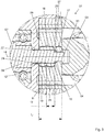
- Fig. 3 shows the formed from the drive shaft 08 and the one rotor representing inner ring 09 rotor assembly of the Fig. 1 and Fig. 2 shown pump unit in detail.
- the circumferential gap 22 is only about 0.04 mm wide. Consequently, the circumferential gap 22 is very small, so that the play in the radial direction between the drive shaft 08 and the inner ring 09 in the second axial section 21 is very small.
- the second axial section 21 forms the fulcrum for the tilting of the inner ring 09 relative to the drive shaft 08.
- the second axial section 21 has an axial length a which is approximately one third of an axial length b of the opening 18.
- the opening 18 On the electric motor 02 (shown in Fig. 2 ) facing side, the opening 18 has a cone-shaped extension 24 in the form of a phase.
- the drive shaft 08 has at the end of the first axial portion 16, which faces the second axial portion 17, a phase 26, which also contributes to the tiltability.
- a phase 26 which also contributes to the tiltability.
- an axially extending clearance 27 is present, so that between the drive shaft 08 and the inner ring 09 is also a game in the axial direction, which also contributes to Verkipp sadness.
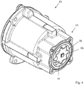
- Fig. 4 shows that in Fig. 1 and Fig. 2 shown pump unit in a perspective detail view, in which the pump 01 is shown in an open state.
- the toothed ring machine formed by the inner ring 09 and the outer ring 11 and the drive shaft 08 can be seen.
- the drive shaft 08 has in the second axial portion 17 (shown in FIG Fig. 3 ) has a square-shaped cross section.
Landscapes
- Engineering & Computer Science (AREA)
- Mechanical Engineering (AREA)
- General Engineering & Computer Science (AREA)
- Details And Applications Of Rotary Liquid Pumps (AREA)
- Rotary Pumps (AREA)
Abstract
Die vorliegende Erfindung betrifft zunächst eine Rotoranordnung für eine Pumpe (01); beispielweise für eine Zahnringmaschine in einem Pumpenaggregat. Die erfindungsgemäße Rotoranordnung umfasst einen Rotor (09) zum Fördern eines Mediums. Der Rotor (19) weist eine Öffnung (18) auf, mit welcher er drehfest auf einer Antriebswelle (08) sitzt. Erfindungsgemäß ist der Rotor (09) an einer axialen Position der Antriebswelle (08) gegenüber der Antriebswelle (08) um jede beliebige Achse senkrecht zur Antriebswelle (08) kippbar. Im Weiteren betrifft die Erfindung ein Pumpenaggregat, welches die erfindungsgemäße Rotoranordnung umfasst.
Description
- Die vorliegende Erfindung betrifft zunächst eine Rotoranordnung für eine Pumpe, beispielsweise für eine Zahnringmaschine in einem Pumpenaggregat. Im Weiteren betrifft die Erfindung ein Pumpenaggregat, welches die erfindungsgemäße Rotoranordnung umfasst.
- Aus dem Stand der Technik sind Pumpen bekannt, in denen eine Zahnradpumpe zum Fördern eines Mediums ausgebildet ist. Derartige Zahnradpumpen sind beispielsweise als eine Zahnringmaschine ausgebildet, welche auch als Gerotor bezeichnet wird. Ein innerer Zahnring bildet einen Rotor der Pumpe, auf welchen infolge des erzeugten Druckes eine Querkraft wirkt, welcher durch eine entsprechende Lagerung entgegengewirkt werden muss. Wenn diese Querkraft nicht hinreichend kompensiert werden kann, kommt es zu einer Verlagerung des Rotors, was sich insbesondere auf die Laufeigenschaften negativ auswirken kann.
- Die
JP 2012-026294 A - Die
JP 2015-048784 A - Aus der
DE 10 2012 204 191 A1 ist eine elektrische Ölpumpe bekannt, bei welcher ein Gehäuse einen Lagerabschnitt zur Lagerung eines spitzen Endabschnittes einer Welle aufweist, um die Welle ergänzend zu stützen. - Die
EP 1 580 431 A1 , dieJP 2015-108306 A
EP 2 570 672 A2 zeigen Zahnradpumpen, bei denen ein äußerer Zahnring durch eine Gleitlagerung gelagert ist. - Die Aufgabe der vorliegenden Erfindung besteht ausgehend vom Stand der Technik darin, den unerwünschten Einfluss einer Querkraft auf den Rotor einer Pumpe aufwandsarm zu minimieren.
- Die genannte Aufgabe wird gelöst durch eine Rotoranordnung gemäß dem beigefügten Anspruch 1 sowie durch ein Pumpenaggregat gemäß dem beigefügten nebengeordneten Anspruch 10.
- Die erfindungsgemäße Rotoranordnung ist für eine Pumpe zum Fördern eines Mediums vorgesehen. Die Pumpe bildet bevorzugt gemeinsam mit einem Elektromotor ein Pumpenaggregat. Die Rotoranordnung umfasst einen Rotor, welcher durch Rotation zum unmittelbaren Fördern des Mediums dient und somit einen Pumpenrotor bildet. Die Ausführung des Rotors ist entsprechend dem angewendeten Prinzip der Pumpe zu wählen. Ist die Pumpe beispielsweise durch eine Zahnradpumpe gebildet, so handelt es sich bei dem Rotor um ein Zahnrad bzw. um einen Zahnring. Bei dem Medium handelt es sich bevorzugt um eine Flüssigkeit, besonders bevorzugt um ein Öl.
- Der Rotor weist eine Öffnung auf, mit welcher er drehfest auf einer Antriebswelle sitzt, sodass eine Rotation der Antriebswelle zu einer Rotation des Rotors führt. Somit ist ein Drehmoment von der Antriebswelle auf den Rotor übertragbar. Die Antriebswelle ragt zumindest in die Öffnung hinein oder bevorzugt durch diese hindurch. Die Öffnung bildet eine Drehachse des Rotors. Die Öffnung stellt eine Nabe des Rotors dar und ist bevorzugt durchgehend ausgebildet. Die Antriebswelle bildet eine Komponente der Rotoranordnung.
- Erfindungsgemäß ist der Rotor in einem Betriebszustand an einer axialen Position der Antriebswelle gegenüber der Antriebswelle um jede beliebige Achse senkrecht zur Antriebswelle kippbar, d. h. verkippbar. Die genannte Achse der Kippbarkeit schneidet die Antriebswelle in der genannten axialen Position der Antriebswelle. Die genannte Achse der Kippbarkeit weist einen beliebigen Drehwinkel in Bezug auf die Antriebswelle auf, sodass die Kippbarkeit des Rotors unabhängig vom Drehwinkel der Antriebswelle ist. Bei dem Betriebszustand handelt es sich um einen Zustand, in welchem der Rotor vollständig auf der Antriebswelle montiert ist, sodass der Rotor drehfest auf der Antriebswelle sitzt und die Rotoranordnung für ihre Funktion in der Pumpe verwendbar ist.
- Da der Rotor an der genannten axialen Position um jede Achse senkrecht zu der der Querkraft nachgebenden Antriebswelle kippbar ist, kann der Rotor einer auftretenden Querkraft folgen, ohne dabei gegenüber der Rotationsachse zu verkippen. Die der Querkraft nachgebende Antriebswelle liegt dann nämlich nicht mehr genau in der Rotationsachse. Da jedoch der Rotor aufgrund seiner Kippbarkeit gegenüber der Antriebswelle in der Rotationsachse verbleiben kann, ist seine Funktion in der Pumpe nicht eingeschränkt. Insbesondere kommt es nicht dazu, dass der Rotor im Falle einer Verkippung gegenüber der Rotationsachse mit einer erhöhten Reibung gegenüber anderen ruhenden oder rotierenden Komponenten der Pumpe rotiert. Vielmehr verlagert sich der Rotor parallel zu seiner Haupterstreckungsebene.
- Ein besonderer Vorteil der erfindungsgemäßen Rotoranordnung besteht darin, dass durch eine aufwandarme Gewährleistung der genannten Verkippbarkeit eine Lagerung der Antriebswelle und des Rotors beidseitig des Rotors nicht notwendig ist. Es bedarf lediglich einer Lagerung auf einer Seite des Rotors, da es dem Rotor erfindungsgemäß ermöglicht ist, gegenüber der der Querkraft nachgebenden Antriebswelle zu verkippen.
- Die Kippbarkeit des Rotors gegenüber der Antriebswelle ist begrenzt, sodass der Rotor bis zu einem maximalen Verkippwinkel gegenüber der Antriebswelle verkippbar ist. Der maximale Verkippwinkel ist bevorzugt so groß, dass eine bei einem Betrieb der Rotoranordnung maximal auftretende Verbiegung der Antriebswelle ausgleichbar ist, sodass der Rotor gegenüber der Rotationsachse nicht verkippt. Der maximale Verkippwinkel beträgt bevorzugt höchstens 5° und besonders bevorzugt höchstens 1°. Der maximale Verkippwinkel beträgt bevorzugt mindestens 0,1° und weiter bevorzugt mindestens 0,5°.
- Die Öffnung weist bevorzugt einen ersten axialen Abschnitt auf, der auch einen ersten axialen Abschnitt der Antriebswelle bildet. In diesem ersten axialen Abschnitt ist in der Öffnung des Rotors zwischen dem Rotor und der Antriebswelle ein um die Antriebswelle umlaufender Spalt ausgebildet, der ein Spiel in radialer Richtung zwischen dem Rotor und der Antriebswelle darstellt. Der umlaufende Spalt ist in axialer Richtung zunehmend ausgebildet. Somit nimmt die sich in radialer Richtung erstreckende Größe des Spaltes, d. h. die Spaltbreite in axialer Richtung zu. Dieser in axialer Richtung größer werdende Spalt erlaubt die erfindungsgemäße Kippbarkeit des Rotors gegenüber der Antriebswelle, ohne dass das Spiel zwischen dem Rotor und der Antriebswelle unnötig groß ist.
- Die genannte radiale Richtung ist auf die Rotationsachse bezogen; d. h. dass die radiale Richtung senkrecht zur Rotationsachse ist, nämlich in Richtung der Radien ausgehend von der Rotationsachse. Die genannte axiale Richtung ist die Richtung der Rotationsachse.
- Der erste axiale Abschnitt umfasst bevorzugt mindestens die Hälfte der axialen Länge der Öffnung und kann aber auch die gesamte axiale Länge der Öffnung umfassen.
- Bei bevorzugten Ausführungsformen der erfindungsgemäßen Rotoranordnung weist die Antriebswelle in einem den Rotor tragenden axialen Bereich, insbesondere im ersten axialen Abschnitt, einen konvexen Längsschnitt auf. Der Längsschnitt liegt in einer Ebene, in welcher auch die Rotationsachse liegt. Die Konvexität ist gegenüber der Wellenlagerfläche in der Öffnung des Rotors ausgebildet und erlaubt die Verkippung des Rotors gegenüber der Antriebswelle.
- Bei bevorzugten Ausführungsformen der erfindungsgemäßen Rotoranordnung weist der Rotor im Bereich seiner Öffnung, insbesondere im ersten axialen Abschnitt seiner Öffnung, einen konvexen Längsschnitt auf. Der Längsschnitt liegt in einer Ebene, in welcher auch die Rotationsachse liegt. Die Konvexität ist gegenüber der Antriebswelle ausgebildet und erlaubt die Verkippung des Rotors gegenüber der Antriebswelle.
- Die Öffnung weist bevorzugt weiterhin einen zweiten axialen Abschnitt auf, der auch einen zweiten axialen Abschnitt der Antriebswelle bildet. Im zweiten axialen Abschnitt besitzt die Öffnung einen unrunden Querschnitt, zu welchem die Antriebswelle einen korrespondierenden Querschnitt besitzt, sodass der Rotor im zweiten axialen Abschnitt formschlüssig auf der Antriebswelle sitzt und ein Drehmoment von der Antriebswelle auf den Rotor übertragbar ist. Der Querschnitt liegt in einer Ebene, die senkrecht zur Antriebswelle bzw. senkrecht zur Öffnung liegt. Der unrunde Querschnitt der Öffnung bzw. der dazu korrespondierende Querschnitt der Antriebswelle ist bevorzugt durch einen Mehrkant oder durch einen Einfach- oder Mehrfachflach gebildet. Der Mehrkant ist bevorzugt durch einen Vierkant gebildet. Das Mehrfachflach ist bevorzugt durch ein Zweiflach gebildet. Zwischen dem unrunden Querschnitt der Öffnung und dem dazu korrespondierenden Querschnitt der Antriebswelle ist in radialer Richtung bevorzugt ein Spiel vorhanden, welches bevorzugt zwischen 0,05 mm und 0,5 mm beträgt.
- Die Antriebswelle weist bevorzugt weiterhin einen axialen Motorabschnitt auf, in welchem die Antriebswelle eine Komponente eines Elektromotors zum Antrieb der Pumpe bildet; insbesondere eine Motorwelle eines Motorrotors. Der axiale Motorabschnitt ist axial beabstandet zum ersten axialen Abschnitt und zum zweiten axialen Abschnitt. Der axiale Motorabschnitt ist axial beabstandet zum Rotor der Pumpe und dessen Öffnung angeordnet. Im Elektromotor wird ein Drehmoment erzeugt und auf die Antriebswelle übertragen. Das Drehmoment wird weiter von der Antriebswelle auf den Rotor der Pumpe übertragen.
- Der erste axiale Abschnitt der Antriebswelle ist bevorzugt axial zwischen dem zweiten axialen Abschnitt und dem axialen Motorabschnitt angeordnet. Dabei ist der zweite axiale Abschnitt der Antriebswelle bevorzugt an einem der beiden axialen Enden der Antriebswelle ausgebildet. Die Antriebswelle ragt mit ihrem axialen Ende bevorzugt vollständig in die Öffnung des Rotors hinein. Dabei kann sie mit einem axialen Spiel durch die Öffnung des Rotors hindurchragen.
- In dem ersten axialen Abschnitt weisen die Öffnung und die Antriebswelle bevorzugt jeweils einen kreisförmigen Querschnitt auf. Der Querschnitt liegt in einer Ebene, die senkrecht zur Antriebswelle bzw. senkrecht zur Öffnung liegt.
- Der erste axiale Abschnitt ist bevorzugt in einen ersten axialen Teilabschnitt und in einen zweiten axialen Teilabschnitt geteilt. Die sich in radialer Richtung erstreckende Größe des umlaufenden Spaltes, d. h. die Spaltbreite ist in den beiden axialen Teilabschnitten jeweils in axialer Richtung konstant, jedoch unterscheidet sie sich zwischen den beiden axialen Teilabschnitten, damit der umlaufende Spalt in axialer Richtung zunehmend ausgebildet ist. Somit ist zwischen den beiden axialen Teilabschnitten eine Stufe des Spaltes ausgebildet. Der abgestufte Spalt kann dadurch gegeben sein, dass die Öffnung im Rotor in den beiden axialen Teilabschnitten unterschiedliche Durchmesser aufweist oder/und dass die Antriebswelle in den beiden axialen Teilabschnitten unterschiedliche Durchmesser aufweist.
- Der umlaufende Spalt weist in den beiden axialen Teilabschnitten bevorzugt jeweils die Form eines Hohlzylinders auf.
- Die Öffnung im Rotor weist im ersten axialen Abschnitt bevorzugt die Form eines Zylinders auf. Insofern die Öffnung in den beiden axialen Teilabschnitten unterschiedliche Durchmesser aufweist, so weist die Öffnung in den beiden axialen Teilabschnitten bevorzugt jeweils die Form eines Zylinders auf.
- Die Antriebswelle weist im ersten axialen Abschnitt bevorzugt die Form eines Zylinders auf. Insofern die Antriebswelle in den beiden axialen Teilabschnitten unterschiedliche Durchmesser aufweist, so weist die Antriebswelle in den beiden axialen Teilabschnitten bevorzugt jeweils die Form eines Zylinders auf.
- Der zweite axiale Teilabschnitt ist bevorzugt zwischen dem ersten axialen Teilabschnitt und dem zweiten axialen Abschnitt angeordnet. Folglich befindet sich der zweite axiale Teilabschnitt in einem mittleren axialen Bereich der Öffnung. Bevorzugt befindet sich der zweite axiale Teilabschnitt in einer axialen Mitte der Öffnung.
- Bevorzugt weist der umlaufende Spalt im zweiten axialen Teilabschnitt eine geringere sich in radialer Richtung erstreckende Größe, d. h. eine geringere Spaltbreite, als im ersten axialen Teilabschnitt auf. Somit ist das Spiel in radialer Richtung zwischen der Antriebswelle und dem Rotor im zweiten axialen Teilabschnitt am kleinsten. Insbesondere ist das Spiel in radialer Richtung zwischen der Antriebswelle und dem Rotor im zweiten axialen Teilabschnitt bevorzugt minimal.
- Der umlaufende Spalt weist im zweiten axialen Teilabschnitt eine sich in radialer Richtung erstreckende Größe, d. h. eine Spaltbreite auf, die bevorzugt zwischen einem Tausendstel und einem Hundertstel des Durchmessers der Antriebswelle im zweiten axialen Teilabschnitt beträgt. Der umlaufende Spalt weist im zweiten axialen Teilabschnitt eine sich in radialer Richtung erstreckende Größe, d. h. eine Spaltbreite auf, die bevorzugt zwischen 0,01 mm und 0,07 mm, besonders bevorzugt zwischen 0,03 mm und 0,05 mm beträgt.
- Der umlaufende Spalt weist im ersten axialen Teilabschnitt eine sich in radialer Richtung erstreckende Größe, d. h. eine Spaltbreite auf, die bevorzugt zwischen einem Hundertstel und einem Zehntel des Durchmessers der Antriebswelle im ersten axialen Teilabschnitt beträgt. Der umlaufende Spalt weist im zweiten axialen Teilabschnitt eine sich in radialer Richtung erstreckende Größe, d. h. eine Spaltbreite auf, die bevorzugt zwischen 0,08 mm und 0,3 mm, besonders bevorzugt zwischen 0,1 mm und 0,2 mm beträgt.
- Der erste axiale Teilabschnitt weist bevorzugt eine axiale Länge auf, die zwischen einem Zehntel und fünf Zehnteln der axialen Länge der Öffnung beträgt. Besonders bevorzugt beträgt diese axiale Länge zwischen zwei Zehnteln und vier Zehnteln der axialen Länge der Öffnung.
- Der zweite axiale Teilabschnitt weist bevorzugt eine axiale Länge auf, die zwischen einem Zehntel und fünf Zehnteln der axialen Länge der Öffnung beträgt. Besonders bevorzugt beträgt diese axiale Länge zwischen zwei Zehnteln und vier Zehnteln der axialen Länge der Öffnung. Der zweite axiale Teilabschnitt weist alternativ bevorzugt eine technisch minimale axiale Länge auf, sodass er eine umlaufende Kante bildet, an der die Antriebswelle und der Rotor mit einem minimalen Spiel in radialer Richtung anstoßen. Diese Kante bildet den Drehpunkt zum Verkippen des Rotors.
- Der zweite axiale Abschnitt weist bevorzugt eine axiale Länge auf, die zwischen einem Zehntel und fünf Zehnteln der axialen Länge der Öffnung beträgt. Besonders bevorzugt beträgt diese axiale Länge zwischen zwei Zehnteln und vier Zehnteln der axialen Länge der Öffnung.
- Die Öffnung weist weiterhin bevorzugt einen axialen Einführungsabschnitt auf, in welchem sie gegenüber dem umlaufenden Spalt erweitert ist. Bevorzugt ist die Öffnung konusförmig gegenüber dem umlaufenden Spalt erweitert. Die Antriebswelle ragt beginnend am Einführungsabschnitt in die Öffnung des Rotors hinein.
- Die Antriebswelle weist im zweiten axialen Abschnitt bevorzugt eine geringere Ausdehnung in radialer Richtung als im ersten axialen Abschnitt auf. So weist die Antriebswelle im zweiten axialen Abschnitt bevorzugt einen äußeren Durchmesser der unrunden Querschnittsform auf, der kleiner als der Durchmesser im ersten axialen Abschnitt, insbesondere kleiner als der Durchmesser im zweiten axialen Teilabschnitt ist.
- Die Antriebswelle weist zwischen dem ersten axialen Abschnitt und dem zweiten axialen Abschnitt bevorzugt eine umlaufende Phase auf, die bevorzugt am Übergang von der größeren Ausdehnung in radialer Richtung im ersten axialen Abschnitt zu der kleineren Ausdehnung in radialer Richtung im zweiten axialen Abschnitt ausgebildet ist. Bei dieser Phase handelt es sich um eine umlaufende Abschrägung des beschriebenen Überganges. Durch die Phase ist eine ausreichende Kippbarkeit gewährleistet, ohne dass es einer größeren Spaltbreite im zweiten axialen Abschnitt bedarf.
- Zwischen dem ersten axialen Abschnitt und dem zweiten axialen Abschnitt ist zwischen der Antriebswelle und dem Rotor bevorzugt ein sich in axialer Richtung erstreckender Freiraum ausgebildet. Dieser Freiraum führt zu einem Spiel in axialer Richtung zwischen der Antriebswelle und dem Rotor, welches ein Anschlagen seitliches Anschlagen beim Verkippen des Rotors verhindert.
- Bei bevorzugten Ausführungsformen der erfindungsgemäßen Rotoranordnung ist die Antriebswelle durch eine Motorwelle eines Elektromotors gebildet. Der Elektromotor ist zum Antrieb des Rotors und somit zum Antrieb der Pumpe ausgebildet. Die Motorwelle weist den oben genannte axialen Motorabschnitt und einen axialen Pumpenabschnitt auf, wobei der axiale Pumpenabschnitt in der Öffnung des Rotors sitzt.
- Die Motorwelle weist bevorzugt genau zwei axiale Lagerabschnitte auf, in denen sie rotativ lagerbar ist; in denen sie insbesondere zur Aufnahme in ein Gleitlager oder in ein Wälzlager ausgebildet ist. Einer der genau zwei Lagerabschnitte ist an einem dem Pumpenabschnitt gegenüberliegenden axialen Ende der Motorwelle angeordnet, sodass er sich im axialen Motorabschnitt befindet. Der andere der genau zwei Lagerabschnitte ist zwischen dem axialen Motorabschnitt und dem axialen Pumpenabschnitt angeordnet.
- Jedenfalls befindet sich bevorzugt an demjenigen axialen Ende der Antriebswelle, welches sich im axialen Pumpenabschnitt befindet, kein Lagerabschnitt, d. h. die Antriebswelle ist dort nicht zur rotativen Lagerung ausgebildet. Es ist nämlich ein besonderer Vorteil der erfindungsgemäßen Rotoranordnung, dass auf eine rotative Lagerung der Antriebswelle an diesem axialen Ende verzichtet werden kann, da sich die Antriebswelle unter Last geringfügig verbiegen kann, ohne dass der Rotor gegenüber der Rotationsachse verkippt wird.
- Der Rotor ist entsprechend dem realisierten Arbeitsprinzip der Pumpe ausgebildet, wobei es sich um ein beliebiges Arbeitsprinzip mit rotierenden Komponenten handeln kann. Bevorzugt handelt es sich bei der Pumpe um eine Zahnradpumpe, insbesondere um eine Zahnringmaschine, die auch als Gerotor bezeichnet wird. Somit ist der Rotor bevorzugt durch ein Zahnrad, insbesondere durch einen inneren Zahnring gebildet.
- Der Rotor, insbesondere der innere Zahnring ist dazu ausgebildet, in der Pumpe ein axiales Spiel von bevorzugt weniger als 0,1 mm, besonders bevorzugt weniger als 0,02 mm aufzuweisen.
- Bei der Pumpe handelt es sich bevorzugt um eine Pumpe zum Fördern einer Betriebsflüssigkeit in einem Kraftfahrzeug; beispielsweise um eine Ölpumpe.
- Das erfindungsgemäße Pumpenaggregat dient zum Fördern eines Mediums. Das Pumpenaggregat umfasst eine in einem axialen Pumpenabschnitt des Pumpenaggregats ausgebildete Pumpe zum unmittelbaren Fördern eines Mediums. Das Pumpenaggregat umfasst weiterhin einen in einem axialen Motorabschnitt des Pumpenaggregats ausgebildeten Elektromotor zum Antrieb der Pumpe. Das Pumpenaggregat umfasst die erfindungsgemäße Rotoranordnung. Die Antriebwelle der Rotoranordnung bildet eine Motorwelle des Elektromotors und ist drehfest mit dem in der Pumpe angeordneten Rotor verbunden. Der Elektromotor besitzt bevorzugt einen die Motorwelle umfassenden Motorrotor und einen Motorstator. Der Rotor der Pumpe ist bevorzugt durch einen Innenring gebildet, wobei die Pumpe bevorzugt weiterhin einen Außenring umfasst, wobei der Innenring und der Außenring eine Zahnringmaschine bilden.
- Das Pumpenaggregat umfasst bevorzugt eine der bevorzugten Ausführungsformen der erfindungsgemäßen Rotoranordnung. Im Übrigen weist das Pumpenaggregat bevorzugt auch diejenigen Merkmale auf, die im Zusammenhang mit der erfindungsgemäßen Rotoranordnung und deren bevorzugten Ausführungsformen angegeben sind.
- Bei dem Pumpenaggregat handelt es sich bevorzugt um eine elektrische Ölpumpe für ein Kraftfahrzeug.
- Weitere Vorteile, Einzelheiten und Weiterbildungen der Erfindung ergeben sich aus der nachfolgenden Beschreibung bevorzugter Ausführungsformen der Erfindung, unter Bezugnahme auf die Zeichnung. Es zeigen:
- Fig. 1:
- eine seitliche Ansicht einer bevorzugten Ausführungsform eines erfindungsgemäßen Pumpenaggregates;
- Fig. 2:
- das in
Fig. 1 gezeigte Pumpenaggregat in einer Längsschnittansicht; - Fig. 3:
- eine erfindungsgemäße Rotoranordnung des in
Fig. 1 gezeigten Pumpenaggregates; und - Fig. 4:
- das in
Fig. 1 gezeigte Pumpenaggregat in einer perspektivischen Detailansicht. -
Fig. 1 zeigt eine seitliche Ansicht einer bevorzugten Ausführungsform eines erfindungsgemäßen Pumpenaggregates, welches zur Förderung von Öl in einem Kraftfahrzeug ausgebildet ist. Das Pumpenaggregat umfasst eine Pumpe 01 und einen Elektromotor 02 zum Antrieb der Pumpe 01. Die Pumpe 01 umfasst einen Einlass 03 und einen Auslass 04 für das zu pumpende Öl. -
Fig. 2 zeigt das inFig. 1 gezeigte Pumpenaggregat in einer Längsschnittansicht. Der Elektromotor 02 umfasst einen Motorstator 06 und einen Motorrotor 07. Der Motorrotor 07 umfasst eine Motorwelle 08, die gleichzeitig eine Antriebswelle der Pumpe 01 bildet. Die Pumpe 01 umfasst einen Innenring 09 und einen Außenring 11, welche eine Zahnringmaschine bilden. Der Innenring 09 sitzt drehfest auf der Antriebswelle 08 und bildet einen Rotor der Pumpe 01. - Die Antriebswelle 08 ist an genau zwei axialen Positionen mit jeweils einem Wälzlager 12 rotativ gelagert; nämlich beidseitig des Motorrotors 07, sodass das eine der beiden Wälzlager 12 axial zwischen dem Motorotor 07 und dem Innenring 09 angeordnet ist. Folglich ist die Antriebswelle 08 nur auf einer der beiden Seiten des Innenringes 09 gelagert, sodass ein in der Pumpe 01 angeordnetes axiales Ende 13 der Antriebswelle 08 nicht gelagert ist.
- Mithilfe der Pumpe 01 ist ein auf das zu fördernde Öl wirkender Druck zwischen 3 bar und 25 bar erzeugbar. Aufgrund des Wirkprinzips der durch den Innenring 09 und den Außenring 11 gebildeten Zahnringmaschine wirkt über den Innenring 09 eine Querkraft auf die Antriebswelle 08 aus Richtung des Einlasses 03. Da die Antriebswelle 08 an ihrem axialen Ende 13 nicht gelagert ist, kommt es zu einer Verbiegung der Antriebswelle 08 im Bereich des axialen Endes 13, sodass die Antriebswelle 08 in diesem Bereich gegenüber einer Rotationsachse 14 verkippt wird. Diese Verkippung führt aber nicht dazu, dass auch der Innenring 09 gegenüber der Rotationsachse 14 verkippt wird, da erfindungsgemäß der Innenring 09 gegenüber der Antriebswelle 08 verkippbar ist. Diese Verkippbarkeit ist unabhängig vom Drehwinkel der Antriebswelle 08 gegeben, sodass der Innenring 09 bei jedem beliebigen Drehwinkel der Antriebswelle 08 gegenüber der Antriebswelle 08 kippbar ist. Diese Verkippbarkeit ist durch eine besondere Gestaltung der Antriebswelle 08 in ihrem den Innenring 09 tragenden axialen Bereich ermöglicht. Dieser axiale Bereich umfasst zunächst einen ersten axialen Abschnitt 16 und einen zweiten axialen Abschnitt 17. Der zweite axiale Abschnitt 17 dient der Übertragung eines Drehmomentes von der Antriebswelle 08 auf den Innenring 09, wofür die Antriebswelle 08 im zweiten axialen Abschnitt 17 als Querschnitt einen Vierkant aufweist, welcher mit einem radialen Spiel von wenigen Zehntel Millimetern im Innenring 09 sitzt. Eine die Antriebswelle 08 aufnehmende Öffnung 18 im Innenring 09 weist im zweiten axialen Abschnitt 17 einen vierkantigen Querschnitt auf, sodass eine drehfeste Verbindung zwischen der Antriebswelle 08 und dem Innenring 09 ausgebildet ist.
- Der erste axiale Abschnitt 16 ist in einen ersten axialen Teilabschnitt 19 und in einen ersten axialen Teilabschnitt 21 geteilt. Im gesamten ersten axialen Abschnitt 16 weisen die Antriebswelle 08 und die Öffnung 18 jeweils einen kreisförmigen Querschnitt auf. Im gesamten ersten axialen Abschnitt 16 ist zwischen der Antriebswelle 08 und dem Innenring 09 in der Öffnung 18 ein umlaufender Spalt 22 (dargestellt in
Fig. 3 ) vorhanden, sodass ein Spiel in radialer Richtung zwischen der Antriebswelle 08 und dem Innenring 09 gegeben ist. Allerdings ist der umlaufende Spalt 22 im ersten axialen Teilabschnitt 19 etwa 0,15 mm und im zweiten axialen Teilabschnitt 21 nur etwa 0,04 mm breit. Folglich ist der Spalt 22 im ersten axialen Teilabschnitt 19 in radialer Richtung größer als im zweiten axialen Teilabschnitt 21. Der umlaufene Spalt 22 kann auch als Freischnitt in der Antriebswelle 08 beschrieben werden. - Die Antriebswelle 08 und der einen Rotor der Pumpe 01 darstellende Innenring 09 bilden eine erfindungsgemäße Rotoranordnung, welche durch die Verkippbarkeit des Rotors 09 gegenüber Antriebswelle 08 unabhängig vom Drehwinkel der Antriebswelle 08 gekennzeichnet ist.
-
Fig. 3 zeigt die aus der Antriebswelle 08 und dem einen Rotor darstellenden Innenring 09 gebildete Rotoranordnung des inFig. 1 und Fig. 2 gezeigten Pumpenaggregates im Detail. Im zweiten axialen Teilabschnitt 21 ist der umlaufende Spalt 22 nur etwa 0,04 mm breit. Folglich ist der umlaufende Spalt 22 sehr klein, sodass das Spiel in radialer Richtung zwischen der Antriebswelle 08 und dem Innenring 09 im zweiten axialen Teilabschnitt 21 sehr klein ist. Der zweite axiale Teilabschnitt 21 bildet den Drehpunkt für die Verkippung des Innenringes 09 gegenüber der Antriebswelle 08. Der zweite axiale Teilabschnitt 21 weist eine axiale Länge a auf, welche etwa ein Drittel einer axialen Länge b der Öffnung 18 beträgt. - Auf der dem Elektromotor 02 (gezeigt in
Fig. 2 ) zugewandten Seite weist die Öffnung 18 eine konusförmige Erweiterung 24 in Form einer Phase auf. Die Antriebswelle 08 weist an demjenigen Ende des ersten axialen Abschnittes 16, welches dem zweiten axialen Abschnitt 17 zugewandt ist, eine Phase 26 auf, welche ebenfalls zur Verkippbarkeit beiträgt. Zwischen dem ersten axialen Abschnitt 16 und dem zweiten axialen Abschnitt 17 ist zwischen der Antriebswelle 08 und dem Innenring 09 ein sich in axialer Richtung erstreckender Freiraum 27 vorhanden, sodass zwischen der Antriebswelle 08 und dem Innenring 09 auch ein Spiel in axialer Richtung gegeben ist, welches ebenfalls zur Verkippbarkeit beiträgt. -
Fig. 4 zeigt das inFig. 1 und Fig. 2 gezeigte Pumpenaggregat in einer perspektivischen Detailansicht, in welcher die Pumpe 01 in einem geöffneten Zustand dargestellt ist. Es sind insbesondere die durch den Innenring 09 und den Außenring 11 gebildete Zahnringmaschine und die Antriebswelle 08 erkennbar. Die Antriebswelle 08 weist im zweiten axialen Abschnitt 17 (gezeigt inFig. 3 ) einen vierkantförmigen Querschnitt auf. -
- 01
- Pumpe
- 02
- Elektromotor
- 03
- Einlass
- 04
- Auslass
- 05
- -
- 06
- Motorstator
- 07
- Motorrotor
- 08
- Motorwelle/Antriebswelle
- 09
- Innenring/Rotor der Pumpe
- 10
- -
- 11
- Außenring
- 12
- Wälzlager
- 13
- axiales Ende
- 14
- Rotationsachse
- 15
- -
- 16
- erster axialer Abschnitt
- 17
- zweiter axialer Abschnitt
- 18
- Öffnung
- 19
- erster axialer Teilabschnitt
- 20
- -
- 21
- zweiter axialer Teilabschnitt
- 22
- umlaufender Spalt
- 23
- -
- 24
- konusförmige Erweiterung
- 25
- -
- 26
- Phase
- 27
- Freiraum
Claims (7)
- Rotoranordnung für eine Pumpe (01), umfassend einen Rotor (09) zum Fördern eines Mediums, welcher eine Öffnung (18) aufweist, mit welcher er auf einer Antriebswelle (08) sitzt, wobei der Rotor (09) drehfest an der Antriebswelle (08) befestigt ist; wobei der Rotor (09) an einer axialen Position der Antriebswelle (08) gegenüber der Antriebswelle (08) um jede beliebige Achse senkrecht zur Antriebswelle (08) kippbar ist; wobei die Öffnung (18) einen ersten axialen Abschnitt (16) aufweist, in welchem zwischen dem Rotor (09) und der Antriebswelle (08) ein umlaufender Spalt (22) ausgebildet ist, der eine sich in radialer Richtung erstreckende Spaltbreite aufweist, die in axialer Richtung zunehmend ausgebildet ist; und wobei die Öffnung (18) weiterhin einen zweiten axialen Abschnitt (17) aufweist, in welchem sie einen unrunden Querschnitt besitzt, zu welchem die Antriebswelle (08) einen korrespondierenden Querschnitt aufweist, sodass der Rotor (09) im zweiten axialen Abschnitt (17) der Öffnung (18) formschlüssig auf der Antriebswelle (08) sitzt, dadurch gekennzeichnet, dass der erste axiale Abschnitt (16) in einen ersten axialen Teilabschnitt (19) und in einen zweiten axialen Teilabschnitt (21) geteilt ist, wobei der Spalt (22) in den beiden axialen Teilabschnitten (19, 21) in axialer Richtung jeweils konstant groß ist, und wobei der Spalt (22) im zweiten axialen Teilabschnitt (21) eine geringere Spaltbreite als im ersten axialen Teilabschnitt (19) aufweist.
- Rotoranordnung nach Anspruch 1, dadurch gekennzeichnet, dass der Rotor (09) im Bereich seiner Öffnung (18) und/oder die Antriebswelle (08) in einem den Rotor (09) tragenden axialen Bereich einen konvexen Längsschnitt aufweist.
- Rotoranordnung nach Anspruch 1 oder 2, dadurch gekennzeichnet, dass der umlaufende Spalt (22) im ersten axialen Teilabschnitt (19) eine Spaltbreite zwischen 0,08 mm und 0,3 mm und im zweiten axialen Teilabschnitt (21) eine Spaltbreite zwischen 0,01 mm und 0,07 mm aufweist.
- Rotoranordnung nach einem der Ansprüche 1 bis 3, dadurch gekennzeichnet, dass die Öffnung (18) weiterhin einen axialen Einführungsabschnitt (24) aufweist, in welchem sie konusförmig gegenüber dem umlaufenden Spalt (22) erweitert ist, wobei die Antriebswelle (08) beginnend am Einführungsabschnitt (24) in die Öffnung (18) des Rotors (09) hineinragt.
- Rotoranordnung nach einem der Ansprüche 1 bis 4, dadurch gekennzeichnet, dass die Antriebswelle (08) weiterhin einen axialen Motorabschnitt aufweist, in welchem die Antriebswelle (08) eine Komponente eines Elektromotors (02) zum Antrieb der Pumpe (01) bildet.
- Rotoranordnung nach einem der Ansprüche 1 bis 5, dadurch gekennzeichnet, dass der Rotor durch einen Innenring (09) einer Zahnringmaschine (09, 11) gebildet ist.
- Pumpenaggregat zum Fördern eines Mediums, umfassend eine in einem axialen Pumpenabschnitt ausgebildete Pumpe (01), einen in einem axialen Motorabschnitt ausgebildeten Elektromotor (02) und eine Rotoranordnung nach einem der Ansprüche 1 bis 6, wobei die Antriebwelle (08) eine Motorwelle des Elektromotors (02) bildet und drehfest mit dem in der Pumpe (01) angeordneten Rotor (09) verbunden ist.
Applications Claiming Priority (1)
| Application Number | Priority Date | Filing Date | Title |
|---|---|---|---|
| DE102016103902.0A DE102016103902B4 (de) | 2016-03-04 | 2016-03-04 | Rotoranordnung für eine Pumpe sowie Pumpenaggregat |
Publications (1)
| Publication Number | Publication Date |
|---|---|
| EP3214310A1 true EP3214310A1 (de) | 2017-09-06 |
Family
ID=58192159
Family Applications (1)
| Application Number | Title | Priority Date | Filing Date |
|---|---|---|---|
| EP17158319.8A Withdrawn EP3214310A1 (de) | 2016-03-04 | 2017-02-28 | Rotoranordnung für eine pumpe sowie pumpenaggregat |
Country Status (2)
| Country | Link |
|---|---|
| EP (1) | EP3214310A1 (de) |
| DE (1) | DE102016103902B4 (de) |
Citations (10)
| Publication number | Priority date | Publication date | Assignee | Title |
|---|---|---|---|---|
| DE102004028127A1 (de) * | 2003-06-11 | 2005-01-05 | Denso Corp., Kariya | Kraftstoffeinspritzpumpe mit einem inneren Aufbau zum Absorbieren einer Winkelverlagerung |
| EP1580431A1 (de) | 2002-12-24 | 2005-09-28 | Koyo Seiko Co., Ltd. | Elektrische innenzahnradpumpe |
| JP2012026294A (ja) | 2010-07-20 | 2012-02-09 | Aisin Seiki Co Ltd | 流体ポンプ |
| DE102011011384A1 (de) * | 2011-02-17 | 2012-08-23 | Festool Gmbh | Hand-Werkzeugmaschine mit einem Lamellenmotor aus einem Nicht-Metall |
| DE102012204191A1 (de) | 2011-03-30 | 2012-10-04 | Hitachi Automotive Systems, Ltd. | Elektrische Ölpumpe |
| EP2570672A2 (de) | 2011-09-17 | 2013-03-20 | Jtekt Corporation | Elektrische Ölpumpe |
| US20140178234A1 (en) * | 2012-12-24 | 2014-06-26 | Denso Corporation | Internal rotor-type fluid machine |
| WO2015019859A1 (ja) * | 2013-08-09 | 2015-02-12 | アイシン精機株式会社 | 流体ポンプ用インナロータ |
| JP2015048784A (ja) | 2013-09-02 | 2015-03-16 | 株式会社ジェイテクト | 電動オイルポンプ装置 |
| JP2015108306A (ja) | 2013-12-03 | 2015-06-11 | 本田技研工業株式会社 | オイルポンプ |
Family Cites Families (3)
| Publication number | Priority date | Publication date | Assignee | Title |
|---|---|---|---|---|
| GB2157803B (en) | 1984-04-25 | 1988-05-18 | Facet Enterprises | Vent-relief valve for a wet motor gerotor fuel pump |
| DE102011000533A1 (de) | 2011-02-07 | 2012-08-09 | Zf Lenksysteme Gmbh | Verstellbare Verdrängerpumpe |
| DE102013223999A1 (de) | 2013-11-25 | 2015-05-28 | Mahle International Gmbh | Flügelzellenpumpe oder Pendelschieberpumpe |
-
2016
- 2016-03-04 DE DE102016103902.0A patent/DE102016103902B4/de active Active
-
2017
- 2017-02-28 EP EP17158319.8A patent/EP3214310A1/de not_active Withdrawn
Patent Citations (11)
| Publication number | Priority date | Publication date | Assignee | Title |
|---|---|---|---|---|
| EP1580431A1 (de) | 2002-12-24 | 2005-09-28 | Koyo Seiko Co., Ltd. | Elektrische innenzahnradpumpe |
| DE102004028127A1 (de) * | 2003-06-11 | 2005-01-05 | Denso Corp., Kariya | Kraftstoffeinspritzpumpe mit einem inneren Aufbau zum Absorbieren einer Winkelverlagerung |
| JP2012026294A (ja) | 2010-07-20 | 2012-02-09 | Aisin Seiki Co Ltd | 流体ポンプ |
| DE102011011384A1 (de) * | 2011-02-17 | 2012-08-23 | Festool Gmbh | Hand-Werkzeugmaschine mit einem Lamellenmotor aus einem Nicht-Metall |
| DE102012204191A1 (de) | 2011-03-30 | 2012-10-04 | Hitachi Automotive Systems, Ltd. | Elektrische Ölpumpe |
| EP2570672A2 (de) | 2011-09-17 | 2013-03-20 | Jtekt Corporation | Elektrische Ölpumpe |
| US20140178234A1 (en) * | 2012-12-24 | 2014-06-26 | Denso Corporation | Internal rotor-type fluid machine |
| WO2015019859A1 (ja) * | 2013-08-09 | 2015-02-12 | アイシン精機株式会社 | 流体ポンプ用インナロータ |
| EP3032102A1 (de) * | 2013-08-09 | 2016-06-15 | Aisin Seiki Kabushiki Kaisha | Innenrotor einer flüssigkeitspumpe |
| JP2015048784A (ja) | 2013-09-02 | 2015-03-16 | 株式会社ジェイテクト | 電動オイルポンプ装置 |
| JP2015108306A (ja) | 2013-12-03 | 2015-06-11 | 本田技研工業株式会社 | オイルポンプ |
Also Published As
| Publication number | Publication date |
|---|---|
| DE102016103902B4 (de) | 2020-06-04 |
| DE102016103902A1 (de) | 2017-09-07 |
Similar Documents
| Publication | Publication Date | Title |
|---|---|---|
| EP3187736B1 (de) | Mehrstufige horizontale zentrifugalpumpe zum fördern eines fluids sowie verfahren zum instandsetzen einer solchen | |
| EP2916007B1 (de) | Schraubenspindelpumpe | |
| EP2211060A2 (de) | Ladeeinrichtung für eine Brennkraftmaschine | |
| EP2233747B1 (de) | Mehrstufiges Kreiselpumpenaggregat | |
| DE10297385B4 (de) | Einstellvorrichtung für die Riemenscheibenbreite eines stufenlos verstellbaren Getriebes | |
| DE19513380A1 (de) | Abdichtung, Lagerung und Antrieb der Rotoren eines trockenlaufenden Schraubenrotorverdichters | |
| DE102010007668B4 (de) | Getriebeelement für ein Spannungswellengetriebe, Nockenwellenversteller sowie Lenkkrafthilfe | |
| EP4072737B1 (de) | Reinigungsvorrichtung | |
| EP2035265B1 (de) | Fahrzeugbremsanlagen-kolbenpumpe | |
| EP3084126B1 (de) | Taumelpumpe mit im stator gelagerter welle | |
| DE102016103902B4 (de) | Rotoranordnung für eine Pumpe sowie Pumpenaggregat | |
| DE4442060C1 (de) | Exzenterschneckenpumpe, insbesondere zum Fördern von Medien mit hoher Viskosität oder hohem Feststoffgehalt | |
| DE19650274A1 (de) | Pumpenaggregat | |
| DE19642021B4 (de) | Hydrostatische Axialkolbenmaschine | |
| EP1777417A1 (de) | Turbolader | |
| WO2017021117A1 (de) | Verdrängerpumpe zur förderung eines fluides für einen verbraucher eines kraftfahrzeuges | |
| WO2021104707A1 (de) | Elektromotorisch angetriebenes aggregat für ein fahrzeug | |
| EP1798417B1 (de) | Vakuumpumpe | |
| EP3001039A2 (de) | Vakuumpumpe | |
| EP4259935B1 (de) | Pumpenvorrichtung für ein hydraulisches system eines kraftfahrzeugs, hydraulisches system | |
| EP4031785B1 (de) | Axial montierbare gleitringdichtungsanordnung | |
| DE102009006275A1 (de) | Fluiddynamisches Lagersystem und Spindelmotor mit einem solchen Lagersysstem | |
| DE4224736A1 (de) | Hydraulikmaschine | |
| DE102018108670B4 (de) | Wellenanordnung sowie elektrischer Antrieb mit der Wellenanordnung | |
| DE102014005002B4 (de) | Antriebssystem für eine Last |
Legal Events
| Date | Code | Title | Description |
|---|---|---|---|
| PUAI | Public reference made under article 153(3) epc to a published international application that has entered the european phase |
Free format text: ORIGINAL CODE: 0009012 |
|
| AK | Designated contracting states |
Kind code of ref document: A1 Designated state(s): AL AT BE BG CH CY CZ DE DK EE ES FI FR GB GR HR HU IE IS IT LI LT LU LV MC MK MT NL NO PL PT RO RS SE SI SK SM TR |
|
| AX | Request for extension of the european patent |
Extension state: BA ME |
|
| STAA | Information on the status of an ep patent application or granted ep patent |
Free format text: STATUS: THE APPLICATION IS DEEMED TO BE WITHDRAWN |
|
| 18D | Application deemed to be withdrawn |
Effective date: 20180307 |