EP3214326A1 - Lineares gleitlager mit kleinem winkelfehler - Google Patents
Lineares gleitlager mit kleinem winkelfehler Download PDFInfo
- Publication number
- EP3214326A1 EP3214326A1 EP16158165.7A EP16158165A EP3214326A1 EP 3214326 A1 EP3214326 A1 EP 3214326A1 EP 16158165 A EP16158165 A EP 16158165A EP 3214326 A1 EP3214326 A1 EP 3214326A1
- Authority
- EP
- European Patent Office
- Prior art keywords
- slider
- guide shaft
- biasing
- bushing
- guide
- Prior art date
- Legal status (The legal status is an assumption and is not a legal conclusion. Google has not performed a legal analysis and makes no representation as to the accuracy of the status listed.)
- Granted
Links
Images


Classifications
-
- F—MECHANICAL ENGINEERING; LIGHTING; HEATING; WEAPONS; BLASTING
- F16—ENGINEERING ELEMENTS AND UNITS; GENERAL MEASURES FOR PRODUCING AND MAINTAINING EFFECTIVE FUNCTIONING OF MACHINES OR INSTALLATIONS; THERMAL INSULATION IN GENERAL
- F16C—SHAFTS; FLEXIBLE SHAFTS; ELEMENTS OR CRANKSHAFT MECHANISMS; ROTARY BODIES OTHER THAN GEARING ELEMENTS; BEARINGS
- F16C29/00—Bearings for parts moving only linearly
- F16C29/12—Arrangements for adjusting play
-
- H—ELECTRICITY
- H02—GENERATION; CONVERSION OR DISTRIBUTION OF ELECTRIC POWER
- H02K—DYNAMO-ELECTRIC MACHINES
- H02K41/00—Propulsion systems in which a rigid body is moved along a path due to dynamo-electric interaction between the body and a magnetic field travelling along the path
- H02K41/02—Linear motors; Sectional motors
- H02K41/03—Synchronous motors; Motors moving step by step; Reluctance motors
- H02K41/031—Synchronous motors; Motors moving step by step; Reluctance motors of the permanent magnet type
-
- F—MECHANICAL ENGINEERING; LIGHTING; HEATING; WEAPONS; BLASTING
- F16—ENGINEERING ELEMENTS AND UNITS; GENERAL MEASURES FOR PRODUCING AND MAINTAINING EFFECTIVE FUNCTIONING OF MACHINES OR INSTALLATIONS; THERMAL INSULATION IN GENERAL
- F16C—SHAFTS; FLEXIBLE SHAFTS; ELEMENTS OR CRANKSHAFT MECHANISMS; ROTARY BODIES OTHER THAN GEARING ELEMENTS; BEARINGS
- F16C29/00—Bearings for parts moving only linearly
- F16C29/002—Elastic or yielding linear bearings or bearing supports
-
- F—MECHANICAL ENGINEERING; LIGHTING; HEATING; WEAPONS; BLASTING
- F16—ENGINEERING ELEMENTS AND UNITS; GENERAL MEASURES FOR PRODUCING AND MAINTAINING EFFECTIVE FUNCTIONING OF MACHINES OR INSTALLATIONS; THERMAL INSULATION IN GENERAL
- F16C—SHAFTS; FLEXIBLE SHAFTS; ELEMENTS OR CRANKSHAFT MECHANISMS; ROTARY BODIES OTHER THAN GEARING ELEMENTS; BEARINGS
- F16C29/00—Bearings for parts moving only linearly
- F16C29/02—Sliding-contact bearings
-
- H—ELECTRICITY
- H02—GENERATION; CONVERSION OR DISTRIBUTION OF ELECTRIC POWER
- H02K—DYNAMO-ELECTRIC MACHINES
- H02K7/00—Arrangements for handling mechanical energy structurally associated with dynamo-electric machines, e.g. structural association with mechanical driving motors or auxiliary dynamo-electric machines
- H02K7/08—Structural association with bearings
-
- F—MECHANICAL ENGINEERING; LIGHTING; HEATING; WEAPONS; BLASTING
- F16—ENGINEERING ELEMENTS AND UNITS; GENERAL MEASURES FOR PRODUCING AND MAINTAINING EFFECTIVE FUNCTIONING OF MACHINES OR INSTALLATIONS; THERMAL INSULATION IN GENERAL
- F16C—SHAFTS; FLEXIBLE SHAFTS; ELEMENTS OR CRANKSHAFT MECHANISMS; ROTARY BODIES OTHER THAN GEARING ELEMENTS; BEARINGS
- F16C2322/00—Apparatus used in shaping articles
- F16C2322/39—General buildup of machine tools, e.g. spindles, slides, actuators
-
- F—MECHANICAL ENGINEERING; LIGHTING; HEATING; WEAPONS; BLASTING
- F16—ENGINEERING ELEMENTS AND UNITS; GENERAL MEASURES FOR PRODUCING AND MAINTAINING EFFECTIVE FUNCTIONING OF MACHINES OR INSTALLATIONS; THERMAL INSULATION IN GENERAL
- F16C—SHAFTS; FLEXIBLE SHAFTS; ELEMENTS OR CRANKSHAFT MECHANISMS; ROTARY BODIES OTHER THAN GEARING ELEMENTS; BEARINGS
- F16C2380/00—Electrical apparatus
- F16C2380/26—Dynamo-electric machines or combinations therewith, e.g. electro-motors and generators
-
- F—MECHANICAL ENGINEERING; LIGHTING; HEATING; WEAPONS; BLASTING
- F16—ENGINEERING ELEMENTS AND UNITS; GENERAL MEASURES FOR PRODUCING AND MAINTAINING EFFECTIVE FUNCTIONING OF MACHINES OR INSTALLATIONS; THERMAL INSULATION IN GENERAL
- F16C—SHAFTS; FLEXIBLE SHAFTS; ELEMENTS OR CRANKSHAFT MECHANISMS; ROTARY BODIES OTHER THAN GEARING ELEMENTS; BEARINGS
- F16C41/00—Other accessories, e.g. devices integrated in the bearing not relating to the bearing function as such
- F16C41/004—Electro-dynamic machines, e.g. motors, generators, actuators
-
- H—ELECTRICITY
- H02—GENERATION; CONVERSION OR DISTRIBUTION OF ELECTRIC POWER
- H02K—DYNAMO-ELECTRIC MACHINES
- H02K2213/00—Specific aspects, not otherwise provided for and not covered by codes H02K2201/00 - H02K2211/00
- H02K2213/09—Machines characterised by the presence of elements which are subject to variation, e.g. adjustable bearings, reconfigurable windings, variable pitch ventilators
Definitions
- the present invention relates to a linear sliding bearing with a particularly small angular error.
- Such sliding bearings serve to move a machine part in a linear direction, without doing additional movements that would change the positioning of the machine part in an undesirable manner.
- rZ This direction of rotation
- a wafer can be pre-adjusted and placed on a table, which is then adjusted in height to reach the focus range of a microscope.
- the orientation of the wafer In order to examine the regions of interest of the wafer, the orientation of the wafer must be maintained down to the Z direction.
- a rotation in rZ would be This is particularly disadvantageous because it would make itself noticeable in peripheral areas of the wafer, ie far away from the center of rotation, by a large displacement of the position sought in the plane of the wafer. It is therefore desirable to have a Z-axis whose angle error is as small as possible.
- this linear guide further allows a certain rotation of the slider relative to the guide shaft, because the wedge profiles are all oriented in the same direction and have only a very small slope. Therefore, the bearing bush or the slider can rotate about the guide shaft, which is particularly easy in one of the two directions of rotation, because here the wedges separate from each other and so the game of the linear guide is increased. In order to move a moving part linearly here and to block its rotation about the linear direction, at least two such linear guides are necessary.
- a linear slide bearing with a guide shaft on which a slider is movably guided in a guide direction, with bushes inserted between the guide shaft and the slider.
- One of these sockets is firmly connected as main bushing with the slider, the other is rotatably supported as a biasing sleeve relative to the slider about the guide direction and thereby biased by a torque.
- Rotations about the guide direction between the slider and the guide shaft are blocked by a respective contact area between the bushes on the one hand and the guide shaft on the other hand in both directions of rotation, wherein the main bushing and the biasing bush are biased by the torque in opposite directions of rotation with respect to the guide shaft backlash.
- the main bush is firmly connected to the slider and takes over the task of centering the slider and guide shaft. It also prevents mutual tilting between the slider and the guide shaft.
- the biasing sleeve in the slider can move freely within certain limits. She is using a spring with connected to the slider, which applies as a torsion spring, the torque for backlash-free bias.
- a slider 3 On a guide shaft 1, a slider 3 is movably held in the guide direction. Between the slider 3 and the guide shaft 1, two sockets 2, 4 are arranged.
- the main socket 2 is firmly connected to the slider 3, for example by gluing.
- the biasing bushing 4 sits with some radial play within the slider 3, so the outer radius of the biasing bushing 4 is slightly smaller than the inner radius of the opening in the slider. 3
- the guide shaft 1 is made of anodized aluminum, the thickness of the oxide layer is about 35 - 40 microns.
- the sockets 2, 4 is suitable specially developed for plain bearings plastic composite in which in addition to the base polymer also embedded fibers or fillers for reinforcement and lubricants to reduce friction are embedded.
- blocking devices 6 protrude into lateral recesses of the preload bushing 4.
- the blocking devices 6 are fastened to the slider 3 by means of screws 7.
- the blocking devices 6 prevent axial slipping, but allow a certain rotation of the biasing bush 4 within the slider 3, because the recesses are wider in the circumferential direction than the blocking devices. 6
- the inner surfaces of the bushes 2, 4 and the outer surface of the guide shaft 1 form contact portions, on which the slider 3 slides along the guide shaft 1. In order to avoid a rotation of the slider 3 relative to the guide shaft 1, these have a rotation about the guide direction blocking, interlocking, symmetrical in themselves maxima and minima. Since such contact areas are always subject to a certain amount of play due to manufacturing tolerances and wear, the main bushing 2 and the biasing bush 4 are biased by a torque in opposite directions of rotation relative to the guide shaft 1. As a result, the play between the bushes 2, 4 and the guide shaft 1 is released, with a displacement of the slider 3 whose angular position is maintained relative to the guide shaft 1.
- the contact areas are wavy, with eight bumps and eight wells on a perimeter have proven to be a good compromise between ease of manufacture and effective suppression of the game.
- a spring 5 which is designed as a torsion spring.
- One end of this torsion spring 5 is fixed by means of an axial screw 9 and a washer 10 to the biasing bushing 4, the other end of the torsion spring 5 is connected by means of an axial pin 8 with the slider 3. In the assembled state, this torsion spring 5 is stretched so that a torque acts between the slider 3 and the biasing bush 4.
- the torque ultimately acts between the main sleeve 2 and the biasing sleeve 4.
- the torque is therefore absorbed by the interlocking maxima and minima of the contact surfaces.
- the maxima and minima are thus urged together in the tangential direction, but in the main bushing 2 and the biasing bushing 4 in opposite directions of rotation.
- the linear plain bearing is biased in both directions.
- the blocking devices 6 and the lateral recesses in the biasing sleeve 4, which receive these blocking devices 6, so must be dimensioned so that they give enough clearance to allow the backlash-free bias between the sockets 2, 4 and the guide shaft 1 , even after a certain wear of the contact areas.
- the spring 5 must have sufficient hardness and preload to prevent the unwanted play even after a certain wear of the contact areas.
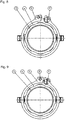
- FIGS. 8 and 9 show an assembly step of the torsion spring 5. While in the FIG. 8 the torsion spring 5 only by means of the screw. 9 attached to the biasing bushing 4 and is still relaxed, the torsion spring 5 was in the FIG. 9 clamped by compression and secured by means of the pin 8 in the tangential direction.
- the screw 9 and the pin 8 can of course also be arranged at the other end of the spring 5.
- the guide shaft 1 is also designed as a hollow shaft. This makes it possible to lay supply lines through the guide shaft 1. Thus, it may be necessary to place a vacuum line at the upper end of the guide shaft 1 in order to hold a wafer there by means of negative pressure, or also to operate the actuators and sensors of an additional fine positioning.
- FIG. 10 finally shows a further embodiment of a linear plain bearing.
- this sliding bearing has an additional electric motor with which the slider 3 can be moved along the guide shaft 1.
- the slider 3 has an annular circumferential U-profile, wherein radially magnetized magnets 12 are mounted in the interior of this U-profile. These interact with a stationary, annularly arranged cylindrical coil 11 which projects into the interior of the U-profile.
- the magnets 12 and the coil 11 form a single-phase electric motor.
Landscapes
- Engineering & Computer Science (AREA)
- General Engineering & Computer Science (AREA)
- Mechanical Engineering (AREA)
- Power Engineering (AREA)
- Physics & Mathematics (AREA)
- Chemical & Material Sciences (AREA)
- Combustion & Propulsion (AREA)
- Electromagnetism (AREA)
- Bearings For Parts Moving Linearly (AREA)
- Motor Or Generator Frames (AREA)
- Sliding-Contact Bearings (AREA)
- Mounting Of Bearings Or Others (AREA)
Abstract
Description
- Die vorliegende Erfindung betrifft ein lineares Gleitlager mit einem besonders kleinen Winkelfehler. Solche Gleitlager dienen dazu, ein Maschinenteil in einer linearen Richtung zu bewegen, ohne dabei zusätzliche Bewegungen auszuführen, die die Positionierung des Maschinenteils in unerwünschter Weise verändern würden.
- In der Halbleiterfertigung besteht an verschiedenen Anlagen und Messinstrumenten die Anforderung, einen Wafer längs einer vertikalen Z-Richtung zu bewegen, ohne ihn während dieser Bewegung um die Z-Achse zu verdrehen. Diese Drehrichtung sei hier als rZ bezeichnet. So kann in einem Inspektionsgerät zur Qualitätskontrolle ein Wafer vorjustiert auf einem Tisch abgelegt werden, der dann in seiner Höhe verstellt wird, um in den Schärfebereich eines Mikroskops zu gelangen. Um die interessierenden Bereiche des Wafers untersuchen zu können, muss die Ausrichtung des Wafers bis auf die Z-Richtung erhalten bleiben. Eine Rotation in rZ wäre dabei besonders nachteilig, weil sie sich in Randbereichen des Wafers, also weit vom Drehzentrum entfernt, durch eine große Verschiebung der aufgesuchten Position in der Ebene des Wafers bemerkbar machen würde. Wünschenswert ist daher eine Z-Achse, deren Winkelfehler möglichst klein ist.
- Aus der
EP 0816013 B1 ist eine spielfrei einstellbare Geradführung bekannt. Zwischen einer Führungswelle und einer Lagerbuchse sorgt hier ein jeweils keilförmiges Profil dafür, dass das Spiel der Führungswelle und der Lagerbuchse durch Verdrehen der Lagerbuchse relativ zur Führungswelle einstellbar ist. Die Lagerbuchse wird am Gleitstück mittels Langlöchern befestigt, so dass das Spiel neu eingestellt werden kann, wenn die Lagerbuchse ihre Form durch Verschleiß geändert hat. Durch das Vorsehen von drei Keilen auf dem Umfang von Lagerbuchse bzw. Führungswelle bleiben die beiden Elemente zueinander zentriert. Es wird auch vorgeschlagen, die Lagerbuchse mittels einer Feder tangential vorzuspannen, so dass bei Verschleiß oder auch bei thermischen Ausdehnungen jederzeit ein spielfreies und dennoch leichtes Gleiten möglich ist. Allerdings ermöglicht diese Geradführung weiterhin eine gewisse Drehung des Gleitstücks relativ zur Führungswelle, denn die Keilprofile sind alle in die gleiche Richtung orientiert und weisen nur eine sehr geringe Steigung auf. Daher kann sich die Lagerbuchse bzw. das Gleitstück um die Führungswelle drehen, wobei dies in einer der beiden Drehrichtungen besonders leicht möglich ist, weil sich hier die Keile voneinander lösen und so das Spiel der Geradführung vergrößert wird. Um hier ein bewegliches Teil linear zu bewegen und dessen Rotation um die lineare Richtung zu blockieren, sind mindestens zwei solcher Geradführungen notwendig. - Es ist daher Aufgabe der Erfindung, ein lineares Gleitlager zu schaffen, bei dem die Rotation des Gleitstücks um die Führungswelle zuverlässig und in beiden Drehrichtungen unterbunden ist, und das dennoch ein leichtes, spielfreies Gleiten des Gleitstücks ermöglicht.
- Diese Aufgabe wird gelöst durch eine Vorrichtung gemäß Anspruch 1. Vorteilhafte Details dieser Vorrichtung ergeben sich auch aus den von Anspruch 1 abhängigen Ansprüchen.
- Es wird ein lineares Gleitlager mit einer Führungswelle offenbart, auf der ein Gleitstück in einer Führungsrichtung beweglich geführt ist, mit zwischen der Führungswelle und dem Gleitstück eingesetzten Buchsen. Eine dieser Buchsen ist als Hauptbuchse fest mit dem Gleitstück verbunden, die andere ist als Vorspannbuchse gegenüber dem Gleitstück um die Führungsrichtung drehbar gehalten und dabei mittels eines Drehmoments vorgespannt. Drehungen um die Führungsrichtung zwischen dem Gleitstück und der Führungswelle sind durch einen jeweiligen Kontaktbereich zwischen den Buchsen einerseits und der Führungswelle andererseits in beiden Drehrichtungen blockiert, wobei die Hauptbuchse und die Vorspannbuchse durch das Drehmoment in entgegengesetzte Drehrichtungen gegenüber der Führungswelle spielfrei vorgespannt sind.
- Durch die gegensinnige Vorspannung der beiden Buchsen des Gleitlagers werden Drehungen des Gleitstücks um die Führungswelle in beiden Drehrichtungen zuverlässig vermieden. Auch wenn sich die Kontaktbereiche über einen längeren Zeitraum abnutzen, hält die Feder die spielfreie Vorspannung aufrecht, so dass auch nach einiger Zeit eine Positionierung eines Wafers ohne Veränderung seiner Ausrichtung bezüglich einer Drehung um die Führungsrichtung ermöglicht wird.
- Die Hauptbuchse ist fest mit dem Gleitstück verbunden und übernimmt vor allem die Aufgabe der Zentrierung von Gleitstück und Führungswelle. Sie verhindert auch ein gegenseitiges Verkippen zwischen dem Gleitstück und der Führungswelle. Im Gegensatz dazu kann sich die Vorspannbuchse im Gleitstück in gewissen Grenzen frei bewegen. Sie ist über eine Feder mit dem Gleitstück verbunden, die als Torsionsfeder das Drehmoment zur spielfreien Vorspannung aufbringt.
- Weitere Details der Erfindung ergeben sich aus der Beschreibung von Ausführungsbeispielen anhand der Figuren.
- Dabei zeigen die
- Figur 1
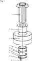
- ein erfindungsgemäßes Gleitlager als erstes Ausführungsbeispiel in einer Explosionsdarstellung,
- Figuren 2 - 7
- verschiedene Ansichten und Schnitte des ersten Ausführungsbeispiels,
- Figuren 8 - 9
- einen Schritt bei der Montage des Gleitlagers, und die
- Figur 10
- ein Gleitlager mit einem integrierten Elektromotor als zweites Ausführungsbeispiel.
- Der Aufbau eines erfindungsgemäßen linearen Gleitlagers lässt sich gut anhand der Zusammenschau der
Figuren 1 - 7 erkennen, die im Folgenden gemeinsam beschrieben werden. - Auf einer Führungswelle 1 ist ein Gleitstück 3 in der Führungsrichtung beweglich gehalten. Zwischen dem Gleitstück 3 und der Führungswelle 1 sind zwei Buchsen 2, 4 angeordnet. Die Hauptbuchse 2 ist dabei fest mit dem Gleitstück 3 verbunden, beispielsweise durch Kleben. Die Vorspannbuchse 4 sitzt dagegen mit etwas radialem Spiel innerhalb des Gleitstücks 3, der äußere Radius der Vorspannbuchse 4 ist also etwas kleiner als der innere Radius der Öffnung im Gleitstück 3.
- Die Führungswelle 1 ist aus anodisiertem Aluminium gefertigt, die Dicke der Oxidschicht beträgt ca. 35 - 40 µm. Für die Buchsen 2, 4 eignet sich ein speziell für Gleitlager entwickelter Kunststoff-Verbund, in dem neben dem Basispolymer auch eingebettete Fasern oder Füllstoffe zur Verstärkung sowie Schmierstoffe zur Verminderung der Reibung eingebettet sind.
- Um die Vorspannbuchse 4 im Gleitstück zu halten, ragen Blockier-Einrichtungen 6 in seitliche Aussparungen der Vorspannbuchse 4. Die Blockier-Einrichtungen 6 sind mittels Schrauben 7 am Gleitstück 3 befestigt. Die Blockier-Einrichtungen 6 verhindern ein axiales Herausrutschen, lassen dabei aber eine gewisse Drehung der Vorspannbuchse 4 innerhalb des Gleitstücks 3 zu, denn die Ausnehmungen sind in Umfangsrichtung breiter als die Blockier-Einrichtungen 6.
- Die Innenflächen der Buchsen 2, 4 und die Außenfläche der Führungswelle 1 bilden Kontaktbereiche, an denen das Gleitstück 3 entlang der Führungswelle 1 gleitet. Um eine Verdrehung des Gleitstücks 3 gegenüber der Führungswelle 1 zu vermeiden, weisen diese eine Drehung um die Führungsrichtung blockierende, ineinander greifende, in sich symmetrische Maxima und Minima auf. Da solche Kontaktbereiche aufgrund von Fertigungstoleranzen und Abnützung immer mit einem gewissen Spiel behaftet sind, werden die Hauptbuchse 2 und die Vorspannbuchse 4 durch ein Drehmoment in entgegengesetzten Drehrichtungen gegenüber der Führungswelle 1 vorgespannt. Dadurch wird das Spiel zwischen den Buchsen 2, 4 und der Führungswelle 1 aufgehoben, bei einer Verschiebung des Gleitstücks 3 wird dessen Winkellage relativ zur Führungswelle 1 beibehalten.
- Die Kontaktbereiche sind wellenförmig ausgebildet, wobei sich jeweils acht Erhebungen und acht Vertiefungen auf einem Umfang als guter Kompromiss zwischen einfacher Herstellbarkeit und wirksamer Unterdrückung des Spiels bewährt haben.
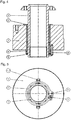
- Das zur Vorspannung benötigte Drehmoment wird von einer Feder 5 aufgebracht, die als Torsionsfeder ausgebildet ist. Das eine Ende dieser Torsionsfeder 5 ist mittels einer axialen Schraube 9 und einer Beilagscheibe 10 an der Vorspannbuchse 4 befestigt, das andere Ende der Torsionsfeder 5 ist mittels eines axialen Stiftes 8 mit dem Gleitstück 3 verbunden. Im montierten Zustand ist diese Torsionsfeder 5 gespannt, so dass zwischen dem Gleitstück 3 und der Vorspannbuchse 4 ein Drehmoment wirkt.
- Da das Gleitstück 3 fest mit der Hauptbuchse 2 verbunden ist, wirkt das Drehmoment letztlich zwischen der Hauptbuchse 2 und der Vorspannbuchse 4. Das Drehmoment wird daher von den ineinandergreifenden Maxima und Minima der Kontaktflächen aufgenommen. Die Maxima und Minima werden somit in tangentialer Richtung aneinander gedrängt, jedoch in der Hauptbuchse 2 und der Vorspannbuchse 4 mit entgegengesetztem Drehsinn. Damit ist das lineare Gleitlager in beiden Drehrichtungen vorgespannt. Die Blockier-Einrichtungen 6 und die seitlichen Ausnehmungen in der Vorspannbuchse 4, die diese Blockier-Einrichtungen 6 aufnehmen, müssen also so dimensioniert sein, dass sie genügend Spiel geben, um die spielfreie Vorspannung zwischen den Buchsen 2, 4 und der Führungswelle 1 zu ermöglichen, auch nach einer gewissen Abnutzung der Kontaktbereiche.
- Ebenso muss die Feder 5 eine ausreichende Härte und Vorspannung aufweisen, um das unerwünschte Spiel auch nach einer gewissen Abnutzung der Kontaktbereiche zu verhindern.
- Über einen längeren Zeitraum kann sich zwar das Gleitstück 3 wegen der Abnutzung der Kontaktbereiche leicht gegenüber der Führungswelle 1 verdrehen, während einem einzelnen Bewegungszyklus ist dieser Effekt aber völlig zu vernachlässigen, die Winkellage ist hier stabil. Ein vorjustiertes Werkstück wie beispielsweise ein Wafer wird seine Ausrichtung behalten.
- Vor allem in der
Figur 4 ist gut zu erkennen, dass die Hauptbuchse 2 in Führungsrichtung deutlich länger ausgebildet ist als die Vorspannbuchse 4. Dies ist der oben bereits erwähnten Tatsache geschuldet, dass die Hauptbuchse 2 vorwiegend die Aufgabe der Führung des Gleitstücks 3 übernimmt, während die Vorspannbuchse 4 vor allem der Erzeugung des benötigten Drehmomentes dient. - Die
Figuren 8 und 9 zeigen einen Montageschritt der Torsionsfeder 5. Während in derFigur 8 die Torsionsfeder 5 lediglich mittels der Schraube 9 an der Vorspannbuchse 4 befestigt und noch entspannt ist, wurde die Torsionsfeder 5 in derFigur 9 durch Zusammendrücken gespannt und mittels des Stiftes 8 in tangentialer Richtung gesichert. Die Schraube 9 und der Stift 8 können natürlich auch jeweils am anderen Ende der Feder 5 angeordnet werden. - Die Führungswelle 1 ist außerdem als Hohlwelle ausgebildet. Damit ist es möglich, Versorgungsleitungen durch die Führungswelle 1 zu legen. So kann es nötig sein, eine Vakuumleitung an das obere Ende der Führungswelle 1 zu legen, um dort einen Wafer mittels Unterdruck zu halten, oder auch um die Aktorik und Sensorik einer zusätzlichen Feinpositionierung zu betreiben.
- Die
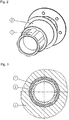
Figur 10 zeigt schließlich ein weiteres Ausführungsbeispiel für ein lineares Gleitlager. Dieses ist weitestgehend gleich aufgebaut wie das erste Ausführungsbeispiel. Dieses Gleitlager weist allerdings einen zusätzlichen Elektromotor auf, mit dem das Gleitstück 3 entlang der Führungswelle 1 bewegt werden kann. Hierzu weist das Gleitstück 3 ein ringförmig umlaufendes U-Profil auf, wobei im Inneren dieses U-Profils radial magnetisierte Magnete 12 angebracht sind. Diese wirken mit einer ortsfesten, ringförmig angeordneten Zylinderspule 11 zusammen, die in das Innere des U-Profils ragt. Die Magnete 12 und die Spule 11 bilden einen einphasigen Elektromotor. - Durch eine geeignete Bestromung der Spule 11 lässt sich so das Gleitstück 3 verschieben. Die Anordnung der Magnete 12 und Spulen 11 kann natürlich vertauscht werden, allerdings mit dem Nachteil, dass dann bewegliche Zuleitungen zur Spule 11 benötigt werden.
Claims (14)
- Lineares Gleitlager mit einer Führungswelle (1), auf der ein Gleitstück (3) in einer Führungsrichtung beweglich geführt ist, mit zwischen der Führungswelle (1) und dem Gleitstück (3) eingesetzten Buchsen (2, 4), wobei eine Hauptbuchse (2) fest mit dem Gleitstück (3) verbunden ist und eine Vorspannbuchse (4) gegenüber dem Gleitstück (3) um die Führungsrichtung drehbar gehalten und dabei mittels eines Drehmoments vorgespannt ist, dadurch gekennzeichnet, dass Drehungen um die Führungsrichtung zwischen dem Gleitstück (3) und der Führungswelle (1) durch einen jeweiligen Kontaktbereich zwischen den Buchsen (2, 4) einerseits und der Führungswelle (1) andererseits in beiden Drehrichtungen blockiert sind, wobei die Hauptbuchse (2) und die Vorspannbuchse (4) durch das Drehmoment in entgegengesetzte Drehrichtungen gegenüber der Führungswelle (1) spielfrei vorgespannt sind.
- Vorrichtung nach Anspruch 1, dadurch gekennzeichnet, dass die Kontaktbereiche zwischen den Buchsen (2, 4) einerseits und der Führungswelle (1) andererseits ineinandergreifende, in sich symmetrische Maxima und Minima aufweisen.
- Vorrichtung nach Anspruch 1 oder 2, dadurch gekennzeichnet, dass die Kontaktbereiche wellenförmig ausgebildet sind.
- Vorrichtung nach Anspruch 2 oder 3, dadurch gekennzeichnet, dass auf einem Umfang der Kontaktbereiche acht Maxima und acht Minima angeordnet sind.
- Vorrichtung nach einem der vorhergehenden Ansprüche, dadurch gekennzeichnet, dass das Drehmoment von einer Feder (5) erzeugt ist, die zwischen der Vorspannbuchse (4) und dem Gleitstück (3) angeordnet ist.
- Vorrichtung nach Anspruch 5, dadurch gekennzeichnet, dass die Feder (5) als Torsionsfeder ausgebildet ist, deren Enden mit der Vorspannbuchse (4) bzw. dem Gleitstück (3) verbunden sind.
- Vorrichtung nach Anspruch 6, dadurch gekennzeichnet, dass die Feder (5) an ihrem einen Ende mittels einer Schraube (9) und an ihrem anderen Ende mittels eines Stiftes (8) befestigt ist, der bei gespannter Feder (5) durch eine Öffnung in der Feder (5) in eine Bohrung im Gleitstück (3) oder in der Vorspannbuchse (4) ragt.
- Vorrichtung nach einem der vorhergehenden Ansprüche, dadurch gekennzeichnet, dass die Vorspannbuchse (4) seitliche Aussparungen aufweist, in die Blockier-Einrichtungen (6) ragen, die fest mit dem Gleitstück (3) verbunden sind, wobei die Aussparungen so dimensioniert sind, dass sich die Vorspannbuchse (4) und das Gleitstück (3) zumindest so weit gegeneinander verdrehen lassen, dass die spielfreie Vorspannung der Buchsen (2, 4) gegenüber der Führungswelle (1) erreicht wird.
- Vorrichtung nach Anspruch 8, dadurch gekennzeichnet, dass der äußere Durchmesser der Vorspannbuchse (4) kleiner ist als der innere Durchmesser des Gleitstücks (1), so dass sich die Vorspannbuchse (4) im Gleitstück (1) frei drehen kann, soweit die Blockier-Einrichtung (6) dies zulässt.
- Vorrichtung nach Anspruch 8 oder 9, dadurch gekennzeichnet, dass die Blockier-Einrichtung (6) ein Herausrutschen der Vorspannbuchse (4) aus dem Gleitstück (3) in der Führungsrichtung verhindert.
- Vorrichtung nach einem der vorhergehenden Ansprüche, dadurch gekennzeichnet, dass die Führungswelle (1) als Hohlwelle ausgebildet ist.
- Vorrichtung nach einem der vorhergehenden Ansprüche, dadurch gekennzeichnet, dass das Gleitstück (3) Magnete (12) oder Spulen (11) trägt, die einen Teil eines Elektromotors bilden, mit dem das Gleitstück (3) längs der Führungswelle (1) verstellbar ist.
- Vorrichtung nach Anspruch 12, dadurch gekennzeichnet, dass das Gleitstück (3) ein ringförmig umlaufendes U-Profil aufweist, wobei die Magnete (12) des Elektromotors im Inneren des U-Profils befestigt sind, und wobei außerdem eine ortsfeste, ringförmige Zylinderspule (11) des Elektromotors in das U-Profil ragt.
- Vorrichtung nach Anspruch 13, dadurch gekennzeichnet, dass die Magnete (12) und die Zylinderspule (11) einen einphasigen Elektromotor bilden.
Priority Applications (4)
| Application Number | Priority Date | Filing Date | Title |
|---|---|---|---|
| EP16158165.7A EP3214326B1 (de) | 2016-03-02 | 2016-03-02 | Lineares gleitlager mit kleinem winkelfehler |
| IL250369A IL250369A0 (en) | 2016-03-02 | 2017-01-31 | A linear bearing moves with a small angular deviation |
| US15/446,013 US10511216B2 (en) | 2016-03-02 | 2017-03-01 | Sliding linear bearing having a small angular error |
| JP2017038918A JP6795428B2 (ja) | 2016-03-02 | 2017-03-02 | 角度誤差の小さい線形滑り軸受装置 |
Applications Claiming Priority (1)
| Application Number | Priority Date | Filing Date | Title |
|---|---|---|---|
| EP16158165.7A EP3214326B1 (de) | 2016-03-02 | 2016-03-02 | Lineares gleitlager mit kleinem winkelfehler |
Publications (2)
| Publication Number | Publication Date |
|---|---|
| EP3214326A1 true EP3214326A1 (de) | 2017-09-06 |
| EP3214326B1 EP3214326B1 (de) | 2018-08-15 |
Family
ID=55456636
Family Applications (1)
| Application Number | Title | Priority Date | Filing Date |
|---|---|---|---|
| EP16158165.7A Active EP3214326B1 (de) | 2016-03-02 | 2016-03-02 | Lineares gleitlager mit kleinem winkelfehler |
Country Status (4)
| Country | Link |
|---|---|
| US (1) | US10511216B2 (de) |
| EP (1) | EP3214326B1 (de) |
| JP (1) | JP6795428B2 (de) |
| IL (1) | IL250369A0 (de) |
Cited By (2)
| Publication number | Priority date | Publication date | Assignee | Title |
|---|---|---|---|---|
| CN113056621A (zh) * | 2018-11-27 | 2021-06-29 | 罗伯特·博世有限公司 | 用于转向系统的滑动轴承衬套 |
| CN116231931A (zh) * | 2023-03-02 | 2023-06-06 | 包头江馨微电机科技有限公司 | 一种导向结构及音圈电机 |
Families Citing this family (4)
| Publication number | Priority date | Publication date | Assignee | Title |
|---|---|---|---|---|
| RU2698015C1 (ru) * | 2018-06-29 | 2019-08-21 | Николай Юрьевич Клюков | Голономный сварочный трактор |
| CN110439924A (zh) * | 2019-08-02 | 2019-11-12 | 台州磊达型钢冷拔有限公司 | 用于导轨上的滑块以及滑块的加工工艺 |
| TWI712487B (zh) * | 2019-12-04 | 2020-12-11 | 東友科技股份有限公司 | 雙軸孔偏心補償裝置 |
| CN112895446B (zh) * | 2019-12-04 | 2023-09-05 | 东友科技股份有限公司 | 双轴孔偏心补偿装置 |
Citations (3)
| Publication number | Priority date | Publication date | Assignee | Title |
|---|---|---|---|---|
| WO1995021336A1 (en) * | 1994-02-01 | 1995-08-10 | Charles William Middleton | Linear bearing with self adjusting mechanism |
| JP2001227536A (ja) * | 2000-02-16 | 2001-08-24 | Sanai:Kk | 位置決め調整装置 |
| EP0816013B1 (de) | 1996-06-26 | 2001-12-12 | Kühl, Hans | Spielfrei einstellbare Geradführung |
Family Cites Families (8)
| Publication number | Priority date | Publication date | Assignee | Title |
|---|---|---|---|---|
| US3805552A (en) * | 1972-10-17 | 1974-04-23 | Atomic Energy Commission | Radial spline guide bearing assembly |
| US4630941A (en) * | 1984-02-21 | 1986-12-23 | International Business Machines Corp. | Tubular squeeze bearing apparatus with rotational restraint |
| US5317221A (en) * | 1991-09-04 | 1994-05-31 | Canon Kabushiki Kaisha | Linear driving device |
| MX9600964A (es) * | 1994-07-14 | 1997-06-28 | Philips Electronics Nv | Actuador electromagnetico que tiene una bobina cilindrica de traslacion y una bobina toroidal de rotacion, una unidad del actuador que comprende al actuador y un sistema de medicino y una maquina que comprende al actuador o a la unidad del actuador. |
| US5777403A (en) * | 1996-07-30 | 1998-07-07 | Nikon Corporation | Voice coil motor with air guide and air bellows |
| TW434984B (en) * | 1997-12-02 | 2001-05-16 | Smc Kk | Electric actuator having detent function |
| BR0102566A (pt) * | 2001-05-14 | 2003-02-25 | Brasil Compressores Sa | Motor linear e compressor linear incluindo dito motor |
| JP2004293631A (ja) * | 2003-03-26 | 2004-10-21 | Ntn Corp | スライドスプライン装置 |
-
2016
- 2016-03-02 EP EP16158165.7A patent/EP3214326B1/de active Active
-
2017
- 2017-01-31 IL IL250369A patent/IL250369A0/en active IP Right Grant
- 2017-03-01 US US15/446,013 patent/US10511216B2/en active Active
- 2017-03-02 JP JP2017038918A patent/JP6795428B2/ja active Active
Patent Citations (3)
| Publication number | Priority date | Publication date | Assignee | Title |
|---|---|---|---|---|
| WO1995021336A1 (en) * | 1994-02-01 | 1995-08-10 | Charles William Middleton | Linear bearing with self adjusting mechanism |
| EP0816013B1 (de) | 1996-06-26 | 2001-12-12 | Kühl, Hans | Spielfrei einstellbare Geradführung |
| JP2001227536A (ja) * | 2000-02-16 | 2001-08-24 | Sanai:Kk | 位置決め調整装置 |
Cited By (4)
| Publication number | Priority date | Publication date | Assignee | Title |
|---|---|---|---|---|
| CN113056621A (zh) * | 2018-11-27 | 2021-06-29 | 罗伯特·博世有限公司 | 用于转向系统的滑动轴承衬套 |
| US12128966B2 (en) | 2018-11-27 | 2024-10-29 | Robert Bosch Gmbh | Sliding bearing bushing for a steering system |
| CN116231931A (zh) * | 2023-03-02 | 2023-06-06 | 包头江馨微电机科技有限公司 | 一种导向结构及音圈电机 |
| CN116231931B (zh) * | 2023-03-02 | 2024-01-05 | 包头江馨微电机科技有限公司 | 一种导向结构及音圈电机 |
Also Published As
| Publication number | Publication date |
|---|---|
| EP3214326B1 (de) | 2018-08-15 |
| JP2017155936A (ja) | 2017-09-07 |
| JP6795428B2 (ja) | 2020-12-02 |
| US20170257014A1 (en) | 2017-09-07 |
| IL250369A0 (en) | 2017-03-30 |
| US10511216B2 (en) | 2019-12-17 |
Similar Documents
| Publication | Publication Date | Title |
|---|---|---|
| EP3214326B1 (de) | Lineares gleitlager mit kleinem winkelfehler | |
| DE3689283T2 (de) | Ausgleichsvorrichtung für die fehlausrichtung bei linearlagern. | |
| DE3027372C2 (de) | ||
| DE19711422A1 (de) | Rollenmutteranordnung und Linearversatzvorrichtung mit einer solchen Rollenmutteranordnung | |
| DE3416207A1 (de) | Linear-kugellageranordnung | |
| DE3829276C2 (de) | Anordnung zum Anstellen von auf einem Tragkörper angeordneten Laufrollen | |
| DE69308506T2 (de) | Gewinderollenmechanismus für ein Raumfahrzeug und Linearstellglied mit einem solchen Mechanismus | |
| DE19930434A1 (de) | Stellglied | |
| EP1610997A1 (de) | Klemmvorrichtung zur lagefixierung einer lenksäule | |
| DE19747146B4 (de) | Linearbewegungsvorrichtung | |
| DE69712849T2 (de) | Höhenverstellung für Positionierungsvorrichtung | |
| EP1637771A2 (de) | Gewindetrieb | |
| DE10201974A1 (de) | Spielfreie Drehlagerung | |
| DE102015109149B4 (de) | Mikroskop mit reibschlüssigen Antrieben | |
| DE10100316C1 (de) | Kamerastativkopf mit Gewichtsausgleich | |
| DE102016003042B4 (de) | Adapter zur Übertragung eines Drehmoments | |
| DE102012010632B4 (de) | Stellvorrichtung zur Ausführung einer Stellbewegung mittels einer Antriebsspindel und Anwendungssystem mit einer solchen Stellvorrichtung | |
| DE9007492U1 (de) | Rollen-Reibschraubantrieb | |
| DE2751390C3 (de) | Winkellagen-Einstellvorrichtung, insbesondere für, optische Messungen | |
| DE102022210549B4 (de) | Linearaktuator | |
| EP3557111B1 (de) | Positioniereinrichtung für alignments schwerer anlagenkomponenten | |
| DE102013210755B4 (de) | Linearantrieb für ein linear geführtes Maschinenteil | |
| DE69217667T2 (de) | Gleitschienenaufbau | |
| DE102018200090B4 (de) | Schneckengetriebe | |
| DE19902048B4 (de) | Wälzlager/Wälzführung zur Abstützung von sich mit unterschiedlicher Geschwindigkeit bewegenden Maschinenteilen, insbesondere für Linearführungen |
Legal Events
| Date | Code | Title | Description |
|---|---|---|---|
| PUAI | Public reference made under article 153(3) epc to a published international application that has entered the european phase |
Free format text: ORIGINAL CODE: 0009012 |
|
| STAA | Information on the status of an ep patent application or granted ep patent |
Free format text: STATUS: THE APPLICATION HAS BEEN PUBLISHED |
|
| AK | Designated contracting states |
Kind code of ref document: A1 Designated state(s): AL AT BE BG CH CY CZ DE DK EE ES FI FR GB GR HR HU IE IS IT LI LT LU LV MC MK MT NL NO PL PT RO RS SE SI SK SM TR |
|
| AX | Request for extension of the european patent |
Extension state: BA ME |
|
| STAA | Information on the status of an ep patent application or granted ep patent |
Free format text: STATUS: REQUEST FOR EXAMINATION WAS MADE |
|
| 17P | Request for examination filed |
Effective date: 20180306 |
|
| RBV | Designated contracting states (corrected) |
Designated state(s): AL AT BE BG CH CY CZ DE DK EE ES FI FR GB GR HR HU IE IS IT LI LT LU LV MC MK MT NL NO PL PT RO RS SE SI SK SM TR |
|
| GRAP | Despatch of communication of intention to grant a patent |
Free format text: ORIGINAL CODE: EPIDOSNIGR1 |
|
| STAA | Information on the status of an ep patent application or granted ep patent |
Free format text: STATUS: GRANT OF PATENT IS INTENDED |
|
| RIC1 | Information provided on ipc code assigned before grant |
Ipc: F16C 29/12 20060101ALI20180326BHEP Ipc: F16C 29/02 20060101AFI20180326BHEP |
|
| INTG | Intention to grant announced |
Effective date: 20180420 |
|
| GRAS | Grant fee paid |
Free format text: ORIGINAL CODE: EPIDOSNIGR3 |
|
| GRAA | (expected) grant |
Free format text: ORIGINAL CODE: 0009210 |
|
| STAA | Information on the status of an ep patent application or granted ep patent |
Free format text: STATUS: THE PATENT HAS BEEN GRANTED |
|
| AK | Designated contracting states |
Kind code of ref document: B1 Designated state(s): AL AT BE BG CH CY CZ DE DK EE ES FI FR GB GR HR HU IE IS IT LI LT LU LV MC MK MT NL NO PL PT RO RS SE SI SK SM TR |
|
| REG | Reference to a national code |
Ref country code: CH Ref legal event code: EP Ref country code: GB Ref legal event code: FG4D Free format text: NOT ENGLISH Ref country code: AT Ref legal event code: REF Ref document number: 1030130 Country of ref document: AT Kind code of ref document: T Effective date: 20180815 |
|
| REG | Reference to a national code |
Ref country code: IE Ref legal event code: FG4D Free format text: LANGUAGE OF EP DOCUMENT: GERMAN |
|
| REG | Reference to a national code |
Ref country code: CH Ref legal event code: NV Representative=s name: ICB INGENIEURS CONSEILS EN BREVETS SA, CH |
|
| REG | Reference to a national code |
Ref country code: DE Ref legal event code: R096 Ref document number: 502016001643 Country of ref document: DE |
|
| REG | Reference to a national code |
Ref country code: NL Ref legal event code: FP |
|
| REG | Reference to a national code |
Ref country code: LT Ref legal event code: MG4D |
|
| PG25 | Lapsed in a contracting state [announced via postgrant information from national office to epo] |
Ref country code: FI Free format text: LAPSE BECAUSE OF FAILURE TO SUBMIT A TRANSLATION OF THE DESCRIPTION OR TO PAY THE FEE WITHIN THE PRESCRIBED TIME-LIMIT Effective date: 20180815 Ref country code: GR Free format text: LAPSE BECAUSE OF FAILURE TO SUBMIT A TRANSLATION OF THE DESCRIPTION OR TO PAY THE FEE WITHIN THE PRESCRIBED TIME-LIMIT Effective date: 20181116 Ref country code: RS Free format text: LAPSE BECAUSE OF FAILURE TO SUBMIT A TRANSLATION OF THE DESCRIPTION OR TO PAY THE FEE WITHIN THE PRESCRIBED TIME-LIMIT Effective date: 20180815 Ref country code: IS Free format text: LAPSE BECAUSE OF FAILURE TO SUBMIT A TRANSLATION OF THE DESCRIPTION OR TO PAY THE FEE WITHIN THE PRESCRIBED TIME-LIMIT Effective date: 20181215 Ref country code: NO Free format text: LAPSE BECAUSE OF FAILURE TO SUBMIT A TRANSLATION OF THE DESCRIPTION OR TO PAY THE FEE WITHIN THE PRESCRIBED TIME-LIMIT Effective date: 20181115 Ref country code: BG Free format text: LAPSE BECAUSE OF FAILURE TO SUBMIT A TRANSLATION OF THE DESCRIPTION OR TO PAY THE FEE WITHIN THE PRESCRIBED TIME-LIMIT Effective date: 20181115 Ref country code: SE Free format text: LAPSE BECAUSE OF FAILURE TO SUBMIT A TRANSLATION OF THE DESCRIPTION OR TO PAY THE FEE WITHIN THE PRESCRIBED TIME-LIMIT Effective date: 20180815 Ref country code: LT Free format text: LAPSE BECAUSE OF FAILURE TO SUBMIT A TRANSLATION OF THE DESCRIPTION OR TO PAY THE FEE WITHIN THE PRESCRIBED TIME-LIMIT Effective date: 20180815 |
|
| PG25 | Lapsed in a contracting state [announced via postgrant information from national office to epo] |
Ref country code: AL Free format text: LAPSE BECAUSE OF FAILURE TO SUBMIT A TRANSLATION OF THE DESCRIPTION OR TO PAY THE FEE WITHIN THE PRESCRIBED TIME-LIMIT Effective date: 20180815 Ref country code: LV Free format text: LAPSE BECAUSE OF FAILURE TO SUBMIT A TRANSLATION OF THE DESCRIPTION OR TO PAY THE FEE WITHIN THE PRESCRIBED TIME-LIMIT Effective date: 20180815 Ref country code: HR Free format text: LAPSE BECAUSE OF FAILURE TO SUBMIT A TRANSLATION OF THE DESCRIPTION OR TO PAY THE FEE WITHIN THE PRESCRIBED TIME-LIMIT Effective date: 20180815 |
|
| PG25 | Lapsed in a contracting state [announced via postgrant information from national office to epo] |
Ref country code: ES Free format text: LAPSE BECAUSE OF FAILURE TO SUBMIT A TRANSLATION OF THE DESCRIPTION OR TO PAY THE FEE WITHIN THE PRESCRIBED TIME-LIMIT Effective date: 20180815 Ref country code: PL Free format text: LAPSE BECAUSE OF FAILURE TO SUBMIT A TRANSLATION OF THE DESCRIPTION OR TO PAY THE FEE WITHIN THE PRESCRIBED TIME-LIMIT Effective date: 20180815 Ref country code: RO Free format text: LAPSE BECAUSE OF FAILURE TO SUBMIT A TRANSLATION OF THE DESCRIPTION OR TO PAY THE FEE WITHIN THE PRESCRIBED TIME-LIMIT Effective date: 20180815 Ref country code: CZ Free format text: LAPSE BECAUSE OF FAILURE TO SUBMIT A TRANSLATION OF THE DESCRIPTION OR TO PAY THE FEE WITHIN THE PRESCRIBED TIME-LIMIT Effective date: 20180815 Ref country code: EE Free format text: LAPSE BECAUSE OF FAILURE TO SUBMIT A TRANSLATION OF THE DESCRIPTION OR TO PAY THE FEE WITHIN THE PRESCRIBED TIME-LIMIT Effective date: 20180815 |
|
| REG | Reference to a national code |
Ref country code: DE Ref legal event code: R097 Ref document number: 502016001643 Country of ref document: DE |
|
| PG25 | Lapsed in a contracting state [announced via postgrant information from national office to epo] |
Ref country code: DK Free format text: LAPSE BECAUSE OF FAILURE TO SUBMIT A TRANSLATION OF THE DESCRIPTION OR TO PAY THE FEE WITHIN THE PRESCRIBED TIME-LIMIT Effective date: 20180815 Ref country code: SM Free format text: LAPSE BECAUSE OF FAILURE TO SUBMIT A TRANSLATION OF THE DESCRIPTION OR TO PAY THE FEE WITHIN THE PRESCRIBED TIME-LIMIT Effective date: 20180815 Ref country code: SK Free format text: LAPSE BECAUSE OF FAILURE TO SUBMIT A TRANSLATION OF THE DESCRIPTION OR TO PAY THE FEE WITHIN THE PRESCRIBED TIME-LIMIT Effective date: 20180815 |
|
| PLBE | No opposition filed within time limit |
Free format text: ORIGINAL CODE: 0009261 |
|
| STAA | Information on the status of an ep patent application or granted ep patent |
Free format text: STATUS: NO OPPOSITION FILED WITHIN TIME LIMIT |
|
| 26N | No opposition filed |
Effective date: 20190516 |
|
| PG25 | Lapsed in a contracting state [announced via postgrant information from national office to epo] |
Ref country code: SI Free format text: LAPSE BECAUSE OF FAILURE TO SUBMIT A TRANSLATION OF THE DESCRIPTION OR TO PAY THE FEE WITHIN THE PRESCRIBED TIME-LIMIT Effective date: 20180815 |
|
| PG25 | Lapsed in a contracting state [announced via postgrant information from national office to epo] |
Ref country code: MC Free format text: LAPSE BECAUSE OF FAILURE TO SUBMIT A TRANSLATION OF THE DESCRIPTION OR TO PAY THE FEE WITHIN THE PRESCRIBED TIME-LIMIT Effective date: 20180815 |
|
| PG25 | Lapsed in a contracting state [announced via postgrant information from national office to epo] |
Ref country code: LU Free format text: LAPSE BECAUSE OF NON-PAYMENT OF DUE FEES Effective date: 20190302 |
|
| REG | Reference to a national code |
Ref country code: BE Ref legal event code: MM Effective date: 20190331 |
|
| PG25 | Lapsed in a contracting state [announced via postgrant information from national office to epo] |
Ref country code: IE Free format text: LAPSE BECAUSE OF NON-PAYMENT OF DUE FEES Effective date: 20190302 |
|
| PG25 | Lapsed in a contracting state [announced via postgrant information from national office to epo] |
Ref country code: BE Free format text: LAPSE BECAUSE OF NON-PAYMENT OF DUE FEES Effective date: 20190331 |
|
| PG25 | Lapsed in a contracting state [announced via postgrant information from national office to epo] |
Ref country code: TR Free format text: LAPSE BECAUSE OF FAILURE TO SUBMIT A TRANSLATION OF THE DESCRIPTION OR TO PAY THE FEE WITHIN THE PRESCRIBED TIME-LIMIT Effective date: 20180815 |
|
| PG25 | Lapsed in a contracting state [announced via postgrant information from national office to epo] |
Ref country code: PT Free format text: LAPSE BECAUSE OF FAILURE TO SUBMIT A TRANSLATION OF THE DESCRIPTION OR TO PAY THE FEE WITHIN THE PRESCRIBED TIME-LIMIT Effective date: 20181215 Ref country code: MT Free format text: LAPSE BECAUSE OF FAILURE TO SUBMIT A TRANSLATION OF THE DESCRIPTION OR TO PAY THE FEE WITHIN THE PRESCRIBED TIME-LIMIT Effective date: 20180815 |
|
| GBPC | Gb: european patent ceased through non-payment of renewal fee |
Effective date: 20200302 |
|
| PG25 | Lapsed in a contracting state [announced via postgrant information from national office to epo] |
Ref country code: GB Free format text: LAPSE BECAUSE OF NON-PAYMENT OF DUE FEES Effective date: 20200302 |
|
| PG25 | Lapsed in a contracting state [announced via postgrant information from national office to epo] |
Ref country code: CY Free format text: LAPSE BECAUSE OF FAILURE TO SUBMIT A TRANSLATION OF THE DESCRIPTION OR TO PAY THE FEE WITHIN THE PRESCRIBED TIME-LIMIT Effective date: 20180815 |
|
| PG25 | Lapsed in a contracting state [announced via postgrant information from national office to epo] |
Ref country code: HU Free format text: LAPSE BECAUSE OF FAILURE TO SUBMIT A TRANSLATION OF THE DESCRIPTION OR TO PAY THE FEE WITHIN THE PRESCRIBED TIME-LIMIT; INVALID AB INITIO Effective date: 20160302 |
|
| PG25 | Lapsed in a contracting state [announced via postgrant information from national office to epo] |
Ref country code: MK Free format text: LAPSE BECAUSE OF FAILURE TO SUBMIT A TRANSLATION OF THE DESCRIPTION OR TO PAY THE FEE WITHIN THE PRESCRIBED TIME-LIMIT Effective date: 20180815 |
|
| PGFP | Annual fee paid to national office [announced via postgrant information from national office to epo] |
Ref country code: CH Payment date: 20250401 Year of fee payment: 10 |
|
| REG | Reference to a national code |
Ref country code: CH Ref legal event code: R17 Free format text: ST27 STATUS EVENT CODE: U-0-0-R10-R17 (AS PROVIDED BY THE NATIONAL OFFICE) Effective date: 20260108 |
|
| REG | Reference to a national code |
Ref country code: CH Ref legal event code: U11 Free format text: ST27 STATUS EVENT CODE: U-0-0-U10-U11 (AS PROVIDED BY THE NATIONAL OFFICE) Effective date: 20260401 |
|
| PGFP | Annual fee paid to national office [announced via postgrant information from national office to epo] |
Ref country code: DE Payment date: 20260319 Year of fee payment: 11 |
|
| PGFP | Annual fee paid to national office [announced via postgrant information from national office to epo] |
Ref country code: AT Payment date: 20260320 Year of fee payment: 11 |
|
| PGFP | Annual fee paid to national office [announced via postgrant information from national office to epo] |
Ref country code: IT Payment date: 20260324 Year of fee payment: 11 |
|
| PGFP | Annual fee paid to national office [announced via postgrant information from national office to epo] |
Ref country code: NL Payment date: 20260319 Year of fee payment: 11 |
|
| PGFP | Annual fee paid to national office [announced via postgrant information from national office to epo] |
Ref country code: FR Payment date: 20260320 Year of fee payment: 11 |