EP3214340A1 - Schneckenreduktionsgetriebe und elektrisch angetriebene hilfsvorrichtung - Google Patents
Schneckenreduktionsgetriebe und elektrisch angetriebene hilfsvorrichtung Download PDFInfo
- Publication number
- EP3214340A1 EP3214340A1 EP15866642.0A EP15866642A EP3214340A1 EP 3214340 A1 EP3214340 A1 EP 3214340A1 EP 15866642 A EP15866642 A EP 15866642A EP 3214340 A1 EP3214340 A1 EP 3214340A1
- Authority
- EP
- European Patent Office
- Prior art keywords
- worm
- axial
- housing
- another side
- side face
- Prior art date
- Legal status (The legal status is an assumption and is not a legal conclusion. Google has not performed a legal analysis and makes no representation as to the accuracy of the status listed.)
- Granted
Links
- 239000003638 chemical reducing agent Substances 0.000 title claims abstract description 50
- 238000005096 rolling process Methods 0.000 claims abstract description 28
- 230000004308 accommodation Effects 0.000 abstract description 37
- 229920001971 elastomer Polymers 0.000 description 5
- 230000009467 reduction Effects 0.000 description 5
- 238000006073 displacement reaction Methods 0.000 description 4
- 230000008878 coupling Effects 0.000 description 3
- 238000010168 coupling process Methods 0.000 description 3
- 238000005859 coupling reaction Methods 0.000 description 3
- 239000000463 material Substances 0.000 description 3
- 230000004323 axial length Effects 0.000 description 2
- 239000000806 elastomer Substances 0.000 description 2
- 230000006872 improvement Effects 0.000 description 2
- 229910000838 Al alloy Inorganic materials 0.000 description 1
- 230000009471 action Effects 0.000 description 1
- 230000005540 biological transmission Effects 0.000 description 1
- 238000004512 die casting Methods 0.000 description 1
- 230000000694 effects Effects 0.000 description 1
- 238000001746 injection moulding Methods 0.000 description 1
- 229910001234 light alloy Inorganic materials 0.000 description 1
- 229920003002 synthetic resin Polymers 0.000 description 1
- 239000000057 synthetic resin Substances 0.000 description 1
Images



Classifications
-
- F—MECHANICAL ENGINEERING; LIGHTING; HEATING; WEAPONS; BLASTING
- F16—ENGINEERING ELEMENTS AND UNITS; GENERAL MEASURES FOR PRODUCING AND MAINTAINING EFFECTIVE FUNCTIONING OF MACHINES OR INSTALLATIONS; THERMAL INSULATION IN GENERAL
- F16H—GEARING
- F16H57/00—General details of gearing
- F16H57/02—Gearboxes; Mounting gearing therein
- F16H57/021—Shaft support structures, e.g. partition walls, bearing eyes, casing walls or covers with bearings
- F16H57/022—Adjustment of gear shafts or bearings
-
- F—MECHANICAL ENGINEERING; LIGHTING; HEATING; WEAPONS; BLASTING
- F16—ENGINEERING ELEMENTS AND UNITS; GENERAL MEASURES FOR PRODUCING AND MAINTAINING EFFECTIVE FUNCTIONING OF MACHINES OR INSTALLATIONS; THERMAL INSULATION IN GENERAL
- F16C—SHAFTS; FLEXIBLE SHAFTS; ELEMENTS OR CRANKSHAFT MECHANISMS; ROTARY BODIES OTHER THAN GEARING ELEMENTS; BEARINGS
- F16C35/00—Rigid support of bearing units; Housings, e.g. caps, covers
- F16C35/04—Rigid support of bearing units; Housings, e.g. caps, covers in the case of ball or roller bearings
- F16C35/06—Mounting or dismounting of ball or roller bearings; Fixing them onto shaft or in housing
- F16C35/067—Fixing them in a housing
-
- B—PERFORMING OPERATIONS; TRANSPORTING
- B62—LAND VEHICLES FOR TRAVELLING OTHERWISE THAN ON RAILS
- B62D—MOTOR VEHICLES; TRAILERS
- B62D5/00—Power-assisted or power-driven steering
- B62D5/04—Power-assisted or power-driven steering electrical, e.g. using an electric servo-motor connected to, or forming part of, the steering gear
- B62D5/0409—Electric motor acting on the steering column
-
- F—MECHANICAL ENGINEERING; LIGHTING; HEATING; WEAPONS; BLASTING
- F16—ENGINEERING ELEMENTS AND UNITS; GENERAL MEASURES FOR PRODUCING AND MAINTAINING EFFECTIVE FUNCTIONING OF MACHINES OR INSTALLATIONS; THERMAL INSULATION IN GENERAL
- F16H—GEARING
- F16H1/00—Toothed gearings for conveying rotary motion
- F16H1/02—Toothed gearings for conveying rotary motion without gears having orbital motion
- F16H1/04—Toothed gearings for conveying rotary motion without gears having orbital motion involving only two intermeshing members
- F16H1/12—Toothed gearings for conveying rotary motion without gears having orbital motion involving only two intermeshing members with non-parallel axes
- F16H1/16—Toothed gearings for conveying rotary motion without gears having orbital motion involving only two intermeshing members with non-parallel axes comprising worm and worm-wheel
-
- F—MECHANICAL ENGINEERING; LIGHTING; HEATING; WEAPONS; BLASTING
- F16—ENGINEERING ELEMENTS AND UNITS; GENERAL MEASURES FOR PRODUCING AND MAINTAINING EFFECTIVE FUNCTIONING OF MACHINES OR INSTALLATIONS; THERMAL INSULATION IN GENERAL
- F16H—GEARING
- F16H57/00—General details of gearing
- F16H57/02—Gearboxes; Mounting gearing therein
- F16H57/039—Gearboxes for accommodating worm gears
-
- F—MECHANICAL ENGINEERING; LIGHTING; HEATING; WEAPONS; BLASTING
- F16—ENGINEERING ELEMENTS AND UNITS; GENERAL MEASURES FOR PRODUCING AND MAINTAINING EFFECTIVE FUNCTIONING OF MACHINES OR INSTALLATIONS; THERMAL INSULATION IN GENERAL
- F16H—GEARING
- F16H57/00—General details of gearing
- F16H57/12—Arrangements for adjusting or for taking-up backlash not provided for elsewhere
-
- F—MECHANICAL ENGINEERING; LIGHTING; HEATING; WEAPONS; BLASTING
- F16—ENGINEERING ELEMENTS AND UNITS; GENERAL MEASURES FOR PRODUCING AND MAINTAINING EFFECTIVE FUNCTIONING OF MACHINES OR INSTALLATIONS; THERMAL INSULATION IN GENERAL
- F16C—SHAFTS; FLEXIBLE SHAFTS; ELEMENTS OR CRANKSHAFT MECHANISMS; ROTARY BODIES OTHER THAN GEARING ELEMENTS; BEARINGS
- F16C19/00—Bearings with rolling contact, for exclusively rotary movement
- F16C19/02—Bearings with rolling contact, for exclusively rotary movement with bearing balls essentially of the same size in one or more circular rows
- F16C19/04—Bearings with rolling contact, for exclusively rotary movement with bearing balls essentially of the same size in one or more circular rows for radial load mainly
- F16C19/06—Bearings with rolling contact, for exclusively rotary movement with bearing balls essentially of the same size in one or more circular rows for radial load mainly with a single row or balls
-
- F—MECHANICAL ENGINEERING; LIGHTING; HEATING; WEAPONS; BLASTING
- F16—ENGINEERING ELEMENTS AND UNITS; GENERAL MEASURES FOR PRODUCING AND MAINTAINING EFFECTIVE FUNCTIONING OF MACHINES OR INSTALLATIONS; THERMAL INSULATION IN GENERAL
- F16C—SHAFTS; FLEXIBLE SHAFTS; ELEMENTS OR CRANKSHAFT MECHANISMS; ROTARY BODIES OTHER THAN GEARING ELEMENTS; BEARINGS
- F16C2361/00—Apparatus or articles in engineering in general
- F16C2361/61—Toothed gear systems, e.g. support of pinion shafts
-
- F—MECHANICAL ENGINEERING; LIGHTING; HEATING; WEAPONS; BLASTING
- F16—ENGINEERING ELEMENTS AND UNITS; GENERAL MEASURES FOR PRODUCING AND MAINTAINING EFFECTIVE FUNCTIONING OF MACHINES OR INSTALLATIONS; THERMAL INSULATION IN GENERAL
- F16H—GEARING
- F16H57/00—General details of gearing
- F16H57/02—Gearboxes; Mounting gearing therein
- F16H57/021—Shaft support structures, e.g. partition walls, bearing eyes, casing walls or covers with bearings
- F16H2057/0213—Support of worm gear shafts
-
- F—MECHANICAL ENGINEERING; LIGHTING; HEATING; WEAPONS; BLASTING
- F16—ENGINEERING ELEMENTS AND UNITS; GENERAL MEASURES FOR PRODUCING AND MAINTAINING EFFECTIVE FUNCTIONING OF MACHINES OR INSTALLATIONS; THERMAL INSULATION IN GENERAL
- F16H—GEARING
- F16H57/00—General details of gearing
- F16H57/02—Gearboxes; Mounting gearing therein
- F16H57/021—Shaft support structures, e.g. partition walls, bearing eyes, casing walls or covers with bearings
- F16H57/022—Adjustment of gear shafts or bearings
- F16H2057/0222—Lateral adjustment
-
- F—MECHANICAL ENGINEERING; LIGHTING; HEATING; WEAPONS; BLASTING
- F16—ENGINEERING ELEMENTS AND UNITS; GENERAL MEASURES FOR PRODUCING AND MAINTAINING EFFECTIVE FUNCTIONING OF MACHINES OR INSTALLATIONS; THERMAL INSULATION IN GENERAL
- F16H—GEARING
- F16H57/00—General details of gearing
- F16H57/12—Arrangements for adjusting or for taking-up backlash not provided for elsewhere
- F16H2057/126—Self-adjusting during operation, e.g. by a spring
Definitions
- the present invention relates to an improvement of a worm reducer to be assembled, for example, in an electric power steering device.
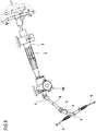
- a steering device for an automobile is configured such that a rotation of a steering wheel 1 is transmitted to an input shaft 3 of a steering gear unit 2, and a pair of left and right tie rods 4, 4 are pushed or pulled along with rotation of the input shaft 3 to apply a steering angle to front wheels.
- the steering wheel 1 is supported and fixed to a rear end portion of a steering shaft 5, and the steering shaft 5 is rotatably supported by a cylindrical steering column 6 while being inserted in the steering column 6 in an axial direction.
- a front end portion of the steering shaft 5 is connected to a rear end portion of an intermediate shaft 8 through a universal joint 7, and a front end portion of the intermediate shaft 8 is connected to the input shaft 3 through another universal joint 9.
- an electric power steering device including an electric assist device for reducing a force required to operate the steering wheel 1 while using an electric motor 10 as an auxiliary power source.
- a reducer is assembled in such an electric power steering device.
- a worm reducer having a large lead angle and reversibility with respect to a transmission direction of the power as described in Patent Document 1 or the like.
- Fig. 9 shows an example of a conventionally widely known worm reducer, the structure of which is different from the structure described in Patent Document 1 though.
- the worm reducer 11 includes a housing 12, a worm wheel 13, and a worm 14.
- the housing 12 is supported and fixed to the electric motor 10 (see Fig. 8 ), and includes a wheel accommodation portion 15 and a worm accommodation portion 16 which is arranged at a skew position with respect to the wheel accommodation portion 15 and has an axial intermediate portion connected to the wheel accommodation portion 15.
- the worm wheel 13 is supported and fixed to a front end side portion of a driven shaft, namely the steering shaft 5 (see Fig. 8 ), concentrically with the steering shaft 5 which is rotatably supported inside the wheel accommodation portion 15.
- a radial clearance 25 is provided between an outer circumferential surface of the worm wheel 13 and an inner circumferential surface of the wheel accommodation portion 15 to prevent the worm wheel 13 from contacting the wheel accommodation portion 15 during operation of the worm reducer 11 (during rotation of the worm wheel 13).
- the thickness (the dimension in the radial direction of the worm wheel 13) t25 of the radial clearance 25 is set to 0.5-2.0 mm although varying according to types of automobile and usage and the like in which the worm reducer 11 is used.
- worm teeth 17 which are provided in an axial (unless otherwise stated, the axial, radial and circumferential direction in the specification and claims refer to the direction with respect to the worm) intermediate portion of the worm 14 is engaged with the worm wheel 13, the worm 14 is rotatably supported inside the worm accommodation portion 16 at two axial positions which interpose the worm teeth 17 by a pair of rolling bearings 18a, 18b of a deep groove ball bearing and the like.
- Such worm 14 is connected with an output shaft of a drive shaft, namely the electric motor 10, at an axial end portion (a base end portion, the right end portion in Fig. 9 ). That is, the worm 14 can be rotationally driven by the electric motor 10.
- the conventional worm reducer as described above has room for improvement. That is, an outer ring 19 configuring the rolling bearing 18a that is supported and fixed on a base end side portion of the worm 14 (the right side in Fig. 9 ) and that is one of the pair of the rolling bearing 18a, 18b is internally fitted to a holding portion 20 that is provided on an opening side portion of the warm accommodation portion 16, and an axial another side face (the left side face in Fig. 9 ) is abutted against a stepped surface 21 formed at an axial another end portion of the holding portion 20.
- a locking groove 22 that is formed circumferentially in a portion adjacent to an axial one side of the holding portion 20 (an portion adjacent to an opposite side of the stepped surface 21) is locked with an inner diameter side portion of a locking ring 23, and the axial another side face of an outer diameter side portion of the locking ring 23 is abutted against the axial one side face of the outer ring 19. Accordingly, the axial displacement of the outer ring 19 is restricted.
- the worm reducer 11 the electric motor 10 is driven
- a counter force is applied to the worm 14 from an engagement portion between the worm teeth 17 that are provided on the worm 14and the worm wheel 13.
- an axial component of the counter force is reversed from the direction of action according to the transmit torque direction from the worm 14 to the worm wheel 13 and is supported by the stepped surface 21 and the locking ring 23. Therefore, an axial thickness of the axial another side of the stepped surface 21 in the housing 12 is required (circumferentially) at least certain degree, so as to sufficiently ensure the strength of that portion.
- a wheel-side support portion 24 having a cross section of a substantially triangular shape is formed in the axial another side of the stepped surface 21.
- An axial dimension of the wheel-side support portion 24 is set to 0.5-2.0 mm although varying according to types of automobile and usage and the like in which the worm reducer 11 is used (the size of the axial component of the counter force that is applied to the worm 14 from the engagement portion).
- the presence of the wheel-side support portion 24 leads to increase of the length of the worm accommodation portion 16 along the axial direction of the worm 14 and enlargement of the worm reducer 11, which is not preferable.
- Patent Document 1 JP-A-2004-306898
- the present invention has been made in consideration of the above-mentioned circumstances for realizing a worm reducer configuration by which reduction in size is easily achieved.
- a worm reducer of the present invention includes a housing, a worm wheel and a worm.
- the worm wheel is supported on a driven shaft rotatably supported by the housing to be concentric with the driven shaft and rotates together with the driven shaft.
- an axial one end portion base end portion
- worm teeth provided on an axial intermediate portion are engaged with the worm wheel
- an axial one side portion with respect to a portion where the worm teeth are provided is rotatably supported by a bearing with respect to the housing.
- the bearing is a rolling bearing which includes: an outer ring having an outer ring raceway on an inner circumferential surface; an inner ring having an inner ring raceway on an outer circumferential surface; and a plurality of rolling elements rotatably arranged between the outer ring raceway and the inner ring raceway. Furthermore, an outer circumferential surface of an axial one end portion of the outer ring is provided with a flange portion which protrudes radially outward.
- the housing is formed with a holding portion to be internally fitted with the outer ring.
- an axial another side face of a retaining plate supported to the housing is abutted against an axial one side face of the flange portion.
- the flange portion is sandwiched in the axial direction between the axial one side face of the housing and the axial another side face of the retaining plate.
- the worm reducer may be preferably configured such that the axial another side face of the outer ring is not abutted against any portion of the housing.
- the flange portion is preferably arranged at an entire circumference or at intervals in the circumferential direction on the outer circumferential surface of the axial one end portion of the outer ring.
- an axial one end portion of the holding portion is provided with a large diameter stepped part, an inner diameter of which is larger than that of an axial another side portion (portion except for the axial one end portion), at an entire circumference or at intervals in the circumferential direction.
- a stepped surface at an axial another end portion of the large diameter stepped part defines the axial one side face of the housing.
- the retaining plate has a stepped shape including an outer diameter side portion supported by the housing and an inner diameter side face abutted against the axial another side face of the flange portion.
- the large diameter stepped part is configured by a pair of recess portions arranged on two radially opposite positions deviated by 90 degrees respectively from an engagement portion between the worm wheel and the worm teeth in the circumferential direction.
- the flange portion is configured by a pair of flange pieces arranged on two radially opposite positions deviated by 90 degrees respectively from the engagement portion between the worm wheel and the worm teeth in the circumferential direction.
- Urging means is provided between the worm and the housing and radially urges the worm (the worm teeth is elastically urged against the worm wheel) to suppress a backlash at the engagement portion between the worm wheel and the worm teeth.
- the electric assist device of the present invention includes an electric motor and a worm reducer.
- the worm reducer includes a housing, a worm wheel, and a worm.
- the worm wheel is supported on a rotational shaft rotatably supported by the housing to be concentric with the rotational shaft and rotates together with the rotational shaft.
- worm teeth are provided on an axial intermediate portion, and in a state where the worm teeth are engaged with the worm wheel, an axial one side portion with respect to a portion where the worm teeth are provided is rotatably supported by a bearing with respect to the housing.
- An output shaft of the electric motor and the worm are connected to transmit torque.
- the electric assist device is configured to increase the torque of the output shaft of the electric motor through the worm reducer and apply the torque to the rotational shaft, i.e. the rotational shaft rotated by the steering wheel supported and fixed on a rear end portion, or a portion movable with the rotation of the rotational shaft (a pinion shaft configuring the steering gear unit or a rotational shaft arranged at an axial portion of a rack configuring the steering gear unit and away from a pinion shaft).
- the worm reducer is the worm reducer of the present invention as described above.
- the output shaft of the electric motor corresponds to the drive shaft
- the rotational shaft corresponds to the driven shaft.
- a flange portion is provided on an outer circumferential surface of the axial one end portion of the outer ring, and the flange portion is sandwiched between the axial one side face of the housing and the axial another side face of the retaining plate supported by the housing.
- the housing in order to support the axial component of the counter force, there is no need to provide the housing with a stepped surface abutted against the axial another side face of the outer ring, and no need to provide the wheel-side support portion 24 for ensuring the strength of the stepped surface 21 against the axial component of the counter force as in the configuration illustrated in the Fig. 9 (even in the where that the axial another side face of the outer ring is abutted against the stepped surface, there is no need to increase the length of the wheel-side support portion in the worm axial direction).
- the length of the housing in the worm axial direction can be reduced, so that the reduction in size of the worm reducer is easily achieved.
- An electric assist device 26 is used while being assembled to, for example, an electric power steering device of so-called column assist type as shown in Fig. 8 , and includes an electric motor 10 and a worm reducer 11a.
- the worm reducer 11a is configured to increase a torque of an output shaft 27 of the electric motor 10, which is then applied to a steering shaft 5 (see Fig. 8 ), and includes a housing 12a, a worm wheel 13, and a worm 14a.
- the housing 12a is supported and fixed to the electric motor 10 and includes a substantially disc shaped wheel accommodation portion 15a arranged to be concentric with the rotational shaft 5, and a substantially cylindrical shaped worm accommodation portion 16a arranged at a skew position with respect to the wheel accommodation portion 15a and having an axial intermediate portion connected (opened) to the wheel accommodation portion 15a.
- This housing 12a is manufactured by die casting a light alloy such as an aluminum alloy or injection molding of synthetic resin.
- the worm wheel 13 is supported on a front end side potion of the steering shaft 5 serving as a driven shaft which is rotatably supported inside the wheel accommodation portion 15a to be concentric with the steering shaft 5 and rotates together with the steering shaft 5.
- a radial clearance 25 is provided between the outer circumferential surface of the worm wheel 13 and the outer circumferential surface of the wheel accommodation portion 15a to prevent the worm wheel 13 from contacting an inner surface of the wheel accommodation portion 15a during operation of the worm reducer 11a (during rotation of the worm wheel 13).
- the worm 14a In a state where worm teeth 17 provided on an axial intermediate portion of the worm 14a is engaged with the worm wheel 13, the worm 14a is rotatably and swingably supported inside the worm accommodation portion 16a at two axial positions which interpose the worm teeth 17 by a pair of rolling bearings 18c, 18d. That is, an inner ring 28 configuring the rolling bearing 18c on the axial one side (the base end side, right side in Figs.
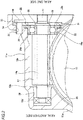
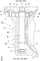
- An outer circumferential surface of the axial one end portion of the outer ring 19a configuring the rolling bearing 18c on the axial one side is formed with a flange portion 30 protruding radially outward at an entire circumference.
- the inner circumferential surface of the axial one end portion of the worm accommodation portion 16a (opening) is formed with a cylindrical surface shaped holding portion 20a except for a portion, and the axial one end portion of the holding portion 20a is formed with a large diameter stepped part 31 having the inner diameter larger than the inner diameter of the axial another side portion (the remainder except for the axial one end portion, a cylindrical surface shaped portion) at an entire circumference.
- the axial another side portion of the outer ring 19a (a cylindrical portion except for the flange portion 30) is internally fitted to the axial another side portion of the holding portion 20a by a clearance fit, and the axial another side face of the flange portion 30 is abutted against a stepped surface 32 (the axial another side face of the housing 12a) provided at the axial another end portion of the large diameter stepped part 31.
- a stepped surface 32 the axial another side face of the housing 12a
- the flange portion 30 of the outer ring 19a is axially sandwiched between the stepped surface 32 and the retaining plate 33. Accordingly, the axial displacement of the outer ring 19a with respect to the worm accommodation portion 16a is restricted. In the present embodiment, the axial another end face of the outer ring 19a is not abutted against (supported by) any portion of the housing 12a.
- the rolling bearing 18c on the axial one side is configured such that the internal clearance is negative (negative clearance) and a center axis of the inner ring 28 can be easily deviated from a center axis of the outer ring 19a. Accordingly, the worm 14a can displace swingingly using the rolling bearing 18c on the axial one side as a center.
- an elastic member such as rubber, may be sandwiched at least one of a portion between the inner circumferential surface of the inner ring 28 and the outer circumferential surface of the worm 14a and a portion between the outer circumferential surface of the axial another side portion of the outer ring 19a and the holding portion 20a, to allow the worm 14a supported by the housing 12a to displace swingingly.
- the outer circumferential portion of the retaining plate 33 includes attachment plate portions 34, 34 which protrude radially outward, at a plurality of positions (three positions in the illustrated example) in the circumferential direction.
- the outer diameter side portion of the retaining plate 33 is supported and fixed to the worm accommodation portion 16a by screwing and fastening bolts 36, 36 which are inserted into through holes 35 formed on each of the attachment plate portions 34, 34 to the threaded hole 37 which opens to the opening side end face of the worm accommodation portion 16a.
- the retaining plate 33 may be supported and fixed to the worm accommodation portion 16a by screwing and fastening nuts on bolts inserted into each of the through holes 35 and into through holes formed to pass through the worm accommodation portion 16a in the axial direction.
- the locking ring as in the conventional configuration illustrated in Fig. 9 may be used.
- the inner ring configuring the rolling bearing 18d on the axial another side of the two rolling bearings 18c, 18d is pressed into the axial another side portion (a tip portion) of the worm 14a (externally fitted by an interference fit).
- the outer ring configuring the rolling bearing 18d on the axial another side is supported by a second holding portion 38 which has a bottomed cylindrical shape and is formed in an inner end portion (the axial another end) of the worm accommodation portion 16a.
- urging means (not shown) is arranged between the second holding portion 38 and the outer ring configuring the rolling bearing 18d on the axial another side and urges against the axial another side portion of the worm 14a in the radial direction (the worm teeth 17 are elastically urged towards the worm wheel 13 (downward in Figs. 1 and 2 )), such that the engagement backlash between the worm wheel 13 and the worm teeth 17 is suppressed and the occurrence of tooth contact noise is suppressed.
- an axial another end portion (the tip portion) of an output shaft 27 of the electric motor 10 is joined with an axial one end portion (the base end portion) of the worm 14a via a torque transmitting joint 39 so as to transmit torque. That is, the torque transmitting joint 39 is provided between a drive-side transmitting member 40 fixed to the axial another end portion of the output shaft 27 and a spline shaft 41 formed in the axial one end portion of the worm 14a.
- the torque transmitting joint 39 is configured by a drive-side elastic member 42 and a driven-side elastic member 43 which are made of elastomer material, such as rubber, and a coupling 44 made of material which is more difficult to deform (higher rigidity) compared to the elastomer material such as rubber. Accordingly, the transmitting characteristics of the torque between the output shaft 27 and the worm 14a can be divided into two stages based on the magnitude of the torque transmitted.
- the torque between the output shaft 27 and the worm 14a can be smoothly transmitted while the coupling 44 is inclined with respect to those axes.
- the details of the torque transmitting joint 39 will not be explained here as it is irrelevant to the subject of the present invention.
- the output shaft 27 may be directly joined with the worm 14a to transmit torque by spline engagement or the like.
- the longitudinal dimension of the worm reducer 11a may be suppressed in the axial direction of the worm 14a so as to achieve reduction in size.
- the flange portion 30 is formed on the outer circumferential surface of the axial one end portion of the outer ring 19a configuring the rolling bearing 18c on the axial one side among the pair of rolling bearings 18c, 18d which rotatably support the worm 14a in the worm accommodation portion 16a.
- the flange portion 30 is sandwiched between the stepped surface 32 formed in the worm accommodation portion 16a and the axial another side face of the retaining plate 33 supported and fixed to the worm accommodation portion 16a.
- the axial dimension of the worm 14a can be reduced, so that the length of the worm reducer 11a in the axial direction of the worm 14a can be reduced.
- the worm reducer 11a and the electric assist device 26 may be reduced in size and weight. As a result, the layout of the electric power steering device assembled with the electric assist device 26 is improved.
- Figs. 4 to 6 show a second embodiment of the present invention.
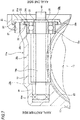
- a large diameter stepped part 31a is formed on an axial one end portion of a holding portion 20b provided on the axial one end side portion of the worm accommodation portion 16b.
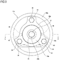
- the large diameter stepped part 31a is configured by a pair of recess portions 45, 45 which are arranged on two radially opposite positions deviated by 90 degrees respectively from the engagement portion between the worm wheel 13 and the worm teeth 17 in a circumferential direction.
- a flange portion 30a which is arranged on an outer circumferential surface of an axial one end portion of an outer ring 19b configuring a rolling bearing 18e on an axial one side (base end side) is configured by a pair of flange pieces 46, 46.
- the pair of flange pieces 46, 46 are arranged on two radially opposite positions deviated by 90 degrees respectively from the engagement portion between the worm wheel 13 and the worm teeth 17 in the circumferential direction.
- both the flange pieces 46, 46 may be formed into cylindrical shape, or the axial side face may define a cylindrical surface to allow the rolling bearing 18e to easily displace swingingly.
- the rolling bearing 18e on the axial one side swings around the two flange pieces 46. Furthermore, in the present embodiment, since the flange portion 30 is configured by the two flange pieces 46, compared with the case where the flange portion 30 is provided at an entire circumference on the outer circumferential surface of the axial one end portion of the outer ring 19 as in the first embodiment, a clearance between the outer circumferential surface of the outer ring 19b and the holding portion 20b is increased. Therefore, the rolling bearing 18e on the axial side is allowed to swing easily, and swing displacement of the worm 14a can be performed smoothly.
- Fig. 7 shows a third embodiment of the present invention.
- the large diameter stepped part 31 is not formed on the axial one end of the holding portion 20a of the worm accommodation portion 16b.
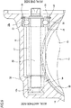
- the axial another side portion of the outer ring 19a (the cylindrical portion expect for the flange portion 30) is internally fitted in the axial another end portion of the holding portion 20a by a clearance fit, and the axial another side face of the flange portion 30 is abutted against the axial one side face (an opening side end face 20c of the holding portion 20a) of the housing 12a, against which the attachment plate portion 34 of the retaining plate 33 abuts.
- a step portion 34a is formed on a radially inner side of the attachment plate portion 34 of the retaining plate 33, and an auxiliary attachment plate portion 34b is formed continuously.
- the axial length of a step between the attachment plate portion 34a and the auxiliary attachment plate portion 34b is shorter than the axial length of the flange portion 30. Therefore, in a state where the retaining plate 33 is fixed to the housing 12a, the axial one side face of the flange portion 30 of the bearing is elastically abutted against the axial another side face of the auxiliary attachment plate portion 34b.
- the axial component of the counter force applied by the engagement portion between the worm wheel 13 and the worm teeth 17 to the worm 14a is supported by the opening side end face 20c of the holding portion 20a and the axial another side face of the auxiliary attachment plate portion 34b.
- the inner ring 28 configuring the rolling bearing 18c is externally fitted to the axial one end side portion of the worm 14a by an interference fit, and the axial another side portion of the outer ring 19a is internally fitted in the axial another side portion of the holding portion 20a by a clearance fit, but the inner ring 28 may be externally fitted in the axial one end side portion of the worm 14a by a clearance fit, and the axial another side portion of the outer ring 19a is internally fitted to the axial another side portion of the holding portion 20a by an interference fit.
- the present invention is no limited to the application to the electric power steering device of column assist type and is applicable to other types of electric power steering device. That is, when the worm reducer is assembled in an electric power steering device of pinion assist type, the worm wheel of the worm reducer is supported and fixed on an input shaft (pinion shaft) of a steering gear unit. On the other hand, when the worm reducer is assembled in an electric power steering device of rack assist type, the worm wheel is supported and fixed on a rotational shaft arranged at an axial portion of a rack configuring the steering gear unit and away from a pinion shaft.
- the present invention is based on Japanese Patent Application No. 2014-251020 filed December 11, 2014 and Japanese Patent Application No. 2015-229838 filed November 25, 2015 , contents of which are incorporated herein by reference.
Landscapes
- Engineering & Computer Science (AREA)
- General Engineering & Computer Science (AREA)
- Mechanical Engineering (AREA)
- Chemical & Material Sciences (AREA)
- Combustion & Propulsion (AREA)
- Transportation (AREA)
- Power Steering Mechanism (AREA)
- Gear Transmission (AREA)
- Mounting Of Bearings Or Others (AREA)
- Rolling Contact Bearings (AREA)
Applications Claiming Priority (3)
| Application Number | Priority Date | Filing Date | Title |
|---|---|---|---|
| JP2014251020 | 2014-12-11 | ||
| JP2015229838 | 2015-11-25 | ||
| PCT/JP2015/084437 WO2016093247A1 (ja) | 2014-12-11 | 2015-12-08 | ウォーム減速機及び電動アシスト装置 |
Publications (3)
| Publication Number | Publication Date |
|---|---|
| EP3214340A1 true EP3214340A1 (de) | 2017-09-06 |
| EP3214340A4 EP3214340A4 (de) | 2017-12-13 |
| EP3214340B1 EP3214340B1 (de) | 2020-07-15 |
Family
ID=56107424
Family Applications (1)
| Application Number | Title | Priority Date | Filing Date |
|---|---|---|---|
| EP15866642.0A Active EP3214340B1 (de) | 2014-12-11 | 2015-12-08 | Schneckenreduktionsgetriebe und elektrisch angetriebene hilfsvorrichtung |
Country Status (5)
| Country | Link |
|---|---|
| US (1) | US20180172134A1 (de) |
| EP (1) | EP3214340B1 (de) |
| JP (1) | JP6315105B2 (de) |
| CN (1) | CN107002821B (de) |
| WO (1) | WO2016093247A1 (de) |
Families Citing this family (3)
| Publication number | Priority date | Publication date | Assignee | Title |
|---|---|---|---|---|
| KR101993295B1 (ko) * | 2017-12-19 | 2019-06-26 | 주식회사 만도 | 전동식 동력 보조 조향장치의 감속기 |
| JP7280763B2 (ja) * | 2019-06-27 | 2023-05-24 | Kyb株式会社 | ウォームシャフト、ウォーム減速機及びウォームシャフトの製造方法 |
| CN111637196A (zh) * | 2020-05-26 | 2020-09-08 | 苏州绿科智能机器人研究院有限公司 | 一种万向减速器 |
Family Cites Families (6)
| Publication number | Priority date | Publication date | Assignee | Title |
|---|---|---|---|---|
| JP2001099173A (ja) * | 1999-09-28 | 2001-04-10 | Fuji Photo Optical Co Ltd | 回転軸の支持構造 |
| JP2004249767A (ja) * | 2003-02-18 | 2004-09-09 | Koyo Seiko Co Ltd | 電動パワーステアリング装置 |
| JP5136233B2 (ja) * | 2008-06-12 | 2013-02-06 | 日本精工株式会社 | 電動式パワーステアリング装置 |
| JP2012040980A (ja) * | 2010-08-20 | 2012-03-01 | Showa Corp | 電動パワーステアリング装置 |
| WO2012173096A1 (ja) * | 2011-06-16 | 2012-12-20 | 日本精工株式会社 | 電動式パワーステアリング装置 |
| JP2014193638A (ja) * | 2013-03-28 | 2014-10-09 | Kayaba Ind Co Ltd | パワーステアリング装置 |
-
2015
- 2015-12-08 WO PCT/JP2015/084437 patent/WO2016093247A1/ja not_active Ceased
- 2015-12-08 JP JP2016563693A patent/JP6315105B2/ja not_active Expired - Fee Related
- 2015-12-08 CN CN201580065180.4A patent/CN107002821B/zh not_active Expired - Fee Related
- 2015-12-08 US US15/525,770 patent/US20180172134A1/en not_active Abandoned
- 2015-12-08 EP EP15866642.0A patent/EP3214340B1/de active Active
Also Published As
| Publication number | Publication date |
|---|---|
| US20180172134A1 (en) | 2018-06-21 |
| EP3214340B1 (de) | 2020-07-15 |
| CN107002821B (zh) | 2019-07-26 |
| CN107002821A (zh) | 2017-08-01 |
| EP3214340A4 (de) | 2017-12-13 |
| JP6315105B2 (ja) | 2018-04-25 |
| WO2016093247A1 (ja) | 2016-06-16 |
| JPWO2016093247A1 (ja) | 2017-04-27 |
Similar Documents
| Publication | Publication Date | Title |
|---|---|---|
| CN104271358B (zh) | 车轮用轴承装置及车轮用轴承装置的制造方法 | |
| EP3263937B1 (de) | Gelenk zur drehmomentübertragung und schneckengetriebe | |
| EP3208480B1 (de) | Drehmomentübertragungskupplung und elektrische servolenkungsvorrichtung | |
| EP3173646B1 (de) | Drehmomentübertragungsgelenk und elektrische servolenkungsvorrichtung | |
| JP6277895B2 (ja) | トルク伝達部材及び駆動軸と被駆動軸との結合部 | |
| US10005490B2 (en) | Electric power steering apparatus | |
| EP3214340B1 (de) | Schneckenreduktionsgetriebe und elektrisch angetriebene hilfsvorrichtung | |
| JP2018024366A (ja) | ステアリング装置 | |
| WO2014103784A1 (ja) | パワーステアリング装置 | |
| CN112829824B (zh) | 电动动力转向聚合物驱动带轮 | |
| JP5618146B2 (ja) | 電動パワーステアリング装置 | |
| JP5136233B2 (ja) | 電動式パワーステアリング装置 | |
| JP5181747B2 (ja) | 電動式パワーステアリング装置 | |
| WO2017086013A1 (ja) | パワーステアリング装置及びこれを備えるステアリング装置 | |
| JP2005205923A (ja) | 電動式パワーステアリング装置 | |
| US10619718B2 (en) | Worm reducer and method of assembling worm reducer | |
| JP2016013798A (ja) | 電動パワーステアリング装置 | |
| KR102149910B1 (ko) | 차량용 전동 스티어링 장치의 플러그 조립체 | |
| JP4501384B2 (ja) | 終減速機のドライブピニオン支持構造 | |
| JP2020067150A (ja) | 動力伝達軸とハブ輪との接続構造 | |
| JP4916273B2 (ja) | スプライン結合構造及びスプライン装置 | |
| JP4924283B2 (ja) | 電動式パワーステアリング装置 | |
| KR102577631B1 (ko) | 회전부재와 하우징의 결합구조 및 이를 구비하는 랙구동형 동력 보조 조향장치 | |
| JP6524937B2 (ja) | 十字軸継手 | |
| JP2016112955A (ja) | パワーステアリング装置 |
Legal Events
| Date | Code | Title | Description |
|---|---|---|---|
| STAA | Information on the status of an ep patent application or granted ep patent |
Free format text: STATUS: THE INTERNATIONAL PUBLICATION HAS BEEN MADE |
|
| PUAI | Public reference made under article 153(3) epc to a published international application that has entered the european phase |
Free format text: ORIGINAL CODE: 0009012 |
|
| STAA | Information on the status of an ep patent application or granted ep patent |
Free format text: STATUS: REQUEST FOR EXAMINATION WAS MADE |
|
| 17P | Request for examination filed |
Effective date: 20170530 |
|
| AK | Designated contracting states |
Kind code of ref document: A1 Designated state(s): AL AT BE BG CH CY CZ DE DK EE ES FI FR GB GR HR HU IE IS IT LI LT LU LV MC MK MT NL NO PL PT RO RS SE SI SK SM TR |
|
| AX | Request for extension of the european patent |
Extension state: BA ME |
|
| A4 | Supplementary search report drawn up and despatched |
Effective date: 20171115 |
|
| RIC1 | Information provided on ipc code assigned before grant |
Ipc: F16C 19/06 20060101ALN20171109BHEP Ipc: F16C 35/067 20060101ALI20171109BHEP Ipc: F16H 1/16 20060101AFI20171109BHEP |
|
| DAV | Request for validation of the european patent (deleted) | ||
| DAX | Request for extension of the european patent (deleted) | ||
| GRAP | Despatch of communication of intention to grant a patent |
Free format text: ORIGINAL CODE: EPIDOSNIGR1 |
|
| STAA | Information on the status of an ep patent application or granted ep patent |
Free format text: STATUS: GRANT OF PATENT IS INTENDED |
|
| RIC1 | Information provided on ipc code assigned before grant |
Ipc: F16H 1/16 20060101AFI20200102BHEP Ipc: F16C 35/067 20060101ALI20200102BHEP Ipc: F16C 19/06 20060101ALN20200102BHEP |
|
| INTG | Intention to grant announced |
Effective date: 20200130 |
|
| GRAS | Grant fee paid |
Free format text: ORIGINAL CODE: EPIDOSNIGR3 |
|
| GRAA | (expected) grant |
Free format text: ORIGINAL CODE: 0009210 |
|
| STAA | Information on the status of an ep patent application or granted ep patent |
Free format text: STATUS: THE PATENT HAS BEEN GRANTED |
|
| AK | Designated contracting states |
Kind code of ref document: B1 Designated state(s): AL AT BE BG CH CY CZ DE DK EE ES FI FR GB GR HR HU IE IS IT LI LT LU LV MC MK MT NL NO PL PT RO RS SE SI SK SM TR |
|
| REG | Reference to a national code |
Ref country code: GB Ref legal event code: FG4D Ref country code: CH Ref legal event code: EP |
|
| REG | Reference to a national code |
Ref country code: DE Ref legal event code: R096 Ref document number: 602015055953 Country of ref document: DE |
|
| REG | Reference to a national code |
Ref country code: IE Ref legal event code: FG4D |
|
| REG | Reference to a national code |
Ref country code: AT Ref legal event code: REF Ref document number: 1291381 Country of ref document: AT Kind code of ref document: T Effective date: 20200815 |
|
| REG | Reference to a national code |
Ref country code: LT Ref legal event code: MG4D |
|
| REG | Reference to a national code |
Ref country code: AT Ref legal event code: MK05 Ref document number: 1291381 Country of ref document: AT Kind code of ref document: T Effective date: 20200715 |
|
| REG | Reference to a national code |
Ref country code: NL Ref legal event code: MP Effective date: 20200715 |
|
| PG25 | Lapsed in a contracting state [announced via postgrant information from national office to epo] |
Ref country code: GR Free format text: LAPSE BECAUSE OF FAILURE TO SUBMIT A TRANSLATION OF THE DESCRIPTION OR TO PAY THE FEE WITHIN THE PRESCRIBED TIME-LIMIT Effective date: 20201016 Ref country code: NO Free format text: LAPSE BECAUSE OF FAILURE TO SUBMIT A TRANSLATION OF THE DESCRIPTION OR TO PAY THE FEE WITHIN THE PRESCRIBED TIME-LIMIT Effective date: 20201015 Ref country code: FI Free format text: LAPSE BECAUSE OF FAILURE TO SUBMIT A TRANSLATION OF THE DESCRIPTION OR TO PAY THE FEE WITHIN THE PRESCRIBED TIME-LIMIT Effective date: 20200715 Ref country code: ES Free format text: LAPSE BECAUSE OF FAILURE TO SUBMIT A TRANSLATION OF THE DESCRIPTION OR TO PAY THE FEE WITHIN THE PRESCRIBED TIME-LIMIT Effective date: 20200715 Ref country code: SE Free format text: LAPSE BECAUSE OF FAILURE TO SUBMIT A TRANSLATION OF THE DESCRIPTION OR TO PAY THE FEE WITHIN THE PRESCRIBED TIME-LIMIT Effective date: 20200715 Ref country code: BG Free format text: LAPSE BECAUSE OF FAILURE TO SUBMIT A TRANSLATION OF THE DESCRIPTION OR TO PAY THE FEE WITHIN THE PRESCRIBED TIME-LIMIT Effective date: 20201015 Ref country code: AT Free format text: LAPSE BECAUSE OF FAILURE TO SUBMIT A TRANSLATION OF THE DESCRIPTION OR TO PAY THE FEE WITHIN THE PRESCRIBED TIME-LIMIT Effective date: 20200715 Ref country code: HR Free format text: LAPSE BECAUSE OF FAILURE TO SUBMIT A TRANSLATION OF THE DESCRIPTION OR TO PAY THE FEE WITHIN THE PRESCRIBED TIME-LIMIT Effective date: 20200715 Ref country code: LT Free format text: LAPSE BECAUSE OF FAILURE TO SUBMIT A TRANSLATION OF THE DESCRIPTION OR TO PAY THE FEE WITHIN THE PRESCRIBED TIME-LIMIT Effective date: 20200715 Ref country code: PT Free format text: LAPSE BECAUSE OF FAILURE TO SUBMIT A TRANSLATION OF THE DESCRIPTION OR TO PAY THE FEE WITHIN THE PRESCRIBED TIME-LIMIT Effective date: 20201116 |
|
| PG25 | Lapsed in a contracting state [announced via postgrant information from national office to epo] |
Ref country code: IS Free format text: LAPSE BECAUSE OF FAILURE TO SUBMIT A TRANSLATION OF THE DESCRIPTION OR TO PAY THE FEE WITHIN THE PRESCRIBED TIME-LIMIT Effective date: 20201115 Ref country code: PL Free format text: LAPSE BECAUSE OF FAILURE TO SUBMIT A TRANSLATION OF THE DESCRIPTION OR TO PAY THE FEE WITHIN THE PRESCRIBED TIME-LIMIT Effective date: 20200715 Ref country code: LV Free format text: LAPSE BECAUSE OF FAILURE TO SUBMIT A TRANSLATION OF THE DESCRIPTION OR TO PAY THE FEE WITHIN THE PRESCRIBED TIME-LIMIT Effective date: 20200715 Ref country code: RS Free format text: LAPSE BECAUSE OF FAILURE TO SUBMIT A TRANSLATION OF THE DESCRIPTION OR TO PAY THE FEE WITHIN THE PRESCRIBED TIME-LIMIT Effective date: 20200715 |
|
| PG25 | Lapsed in a contracting state [announced via postgrant information from national office to epo] |
Ref country code: NL Free format text: LAPSE BECAUSE OF FAILURE TO SUBMIT A TRANSLATION OF THE DESCRIPTION OR TO PAY THE FEE WITHIN THE PRESCRIBED TIME-LIMIT Effective date: 20200715 |
|
| REG | Reference to a national code |
Ref country code: DE Ref legal event code: R097 Ref document number: 602015055953 Country of ref document: DE |
|
| PG25 | Lapsed in a contracting state [announced via postgrant information from national office to epo] |
Ref country code: CZ Free format text: LAPSE BECAUSE OF FAILURE TO SUBMIT A TRANSLATION OF THE DESCRIPTION OR TO PAY THE FEE WITHIN THE PRESCRIBED TIME-LIMIT Effective date: 20200715 Ref country code: DK Free format text: LAPSE BECAUSE OF FAILURE TO SUBMIT A TRANSLATION OF THE DESCRIPTION OR TO PAY THE FEE WITHIN THE PRESCRIBED TIME-LIMIT Effective date: 20200715 Ref country code: IT Free format text: LAPSE BECAUSE OF FAILURE TO SUBMIT A TRANSLATION OF THE DESCRIPTION OR TO PAY THE FEE WITHIN THE PRESCRIBED TIME-LIMIT Effective date: 20200715 Ref country code: EE Free format text: LAPSE BECAUSE OF FAILURE TO SUBMIT A TRANSLATION OF THE DESCRIPTION OR TO PAY THE FEE WITHIN THE PRESCRIBED TIME-LIMIT Effective date: 20200715 Ref country code: RO Free format text: LAPSE BECAUSE OF FAILURE TO SUBMIT A TRANSLATION OF THE DESCRIPTION OR TO PAY THE FEE WITHIN THE PRESCRIBED TIME-LIMIT Effective date: 20200715 Ref country code: SM Free format text: LAPSE BECAUSE OF FAILURE TO SUBMIT A TRANSLATION OF THE DESCRIPTION OR TO PAY THE FEE WITHIN THE PRESCRIBED TIME-LIMIT Effective date: 20200715 |
|
| PLBE | No opposition filed within time limit |
Free format text: ORIGINAL CODE: 0009261 |
|
| STAA | Information on the status of an ep patent application or granted ep patent |
Free format text: STATUS: NO OPPOSITION FILED WITHIN TIME LIMIT |
|
| PG25 | Lapsed in a contracting state [announced via postgrant information from national office to epo] |
Ref country code: AL Free format text: LAPSE BECAUSE OF FAILURE TO SUBMIT A TRANSLATION OF THE DESCRIPTION OR TO PAY THE FEE WITHIN THE PRESCRIBED TIME-LIMIT Effective date: 20200715 |
|
| 26N | No opposition filed |
Effective date: 20210416 |
|
| PG25 | Lapsed in a contracting state [announced via postgrant information from national office to epo] |
Ref country code: SK Free format text: LAPSE BECAUSE OF FAILURE TO SUBMIT A TRANSLATION OF THE DESCRIPTION OR TO PAY THE FEE WITHIN THE PRESCRIBED TIME-LIMIT Effective date: 20200715 |
|
| REG | Reference to a national code |
Ref country code: CH Ref legal event code: PL |
|
| GBPC | Gb: european patent ceased through non-payment of renewal fee |
Effective date: 20201208 |
|
| PG25 | Lapsed in a contracting state [announced via postgrant information from national office to epo] |
Ref country code: SI Free format text: LAPSE BECAUSE OF FAILURE TO SUBMIT A TRANSLATION OF THE DESCRIPTION OR TO PAY THE FEE WITHIN THE PRESCRIBED TIME-LIMIT Effective date: 20200715 Ref country code: MC Free format text: LAPSE BECAUSE OF FAILURE TO SUBMIT A TRANSLATION OF THE DESCRIPTION OR TO PAY THE FEE WITHIN THE PRESCRIBED TIME-LIMIT Effective date: 20200715 |
|
| REG | Reference to a national code |
Ref country code: BE Ref legal event code: MM Effective date: 20201231 |
|
| PG25 | Lapsed in a contracting state [announced via postgrant information from national office to epo] |
Ref country code: FR Free format text: LAPSE BECAUSE OF NON-PAYMENT OF DUE FEES Effective date: 20201231 Ref country code: LU Free format text: LAPSE BECAUSE OF NON-PAYMENT OF DUE FEES Effective date: 20201208 Ref country code: IE Free format text: LAPSE BECAUSE OF NON-PAYMENT OF DUE FEES Effective date: 20201208 |
|
| PG25 | Lapsed in a contracting state [announced via postgrant information from national office to epo] |
Ref country code: LI Free format text: LAPSE BECAUSE OF NON-PAYMENT OF DUE FEES Effective date: 20201231 Ref country code: GB Free format text: LAPSE BECAUSE OF NON-PAYMENT OF DUE FEES Effective date: 20201208 Ref country code: CH Free format text: LAPSE BECAUSE OF NON-PAYMENT OF DUE FEES Effective date: 20201231 |
|
| PGFP | Annual fee paid to national office [announced via postgrant information from national office to epo] |
Ref country code: DE Payment date: 20211102 Year of fee payment: 7 |
|
| PG25 | Lapsed in a contracting state [announced via postgrant information from national office to epo] |
Ref country code: IS Free format text: LAPSE BECAUSE OF FAILURE TO SUBMIT A TRANSLATION OF THE DESCRIPTION OR TO PAY THE FEE WITHIN THE PRESCRIBED TIME-LIMIT Effective date: 20201115 Ref country code: TR Free format text: LAPSE BECAUSE OF FAILURE TO SUBMIT A TRANSLATION OF THE DESCRIPTION OR TO PAY THE FEE WITHIN THE PRESCRIBED TIME-LIMIT Effective date: 20200715 Ref country code: MT Free format text: LAPSE BECAUSE OF FAILURE TO SUBMIT A TRANSLATION OF THE DESCRIPTION OR TO PAY THE FEE WITHIN THE PRESCRIBED TIME-LIMIT Effective date: 20200715 Ref country code: CY Free format text: LAPSE BECAUSE OF FAILURE TO SUBMIT A TRANSLATION OF THE DESCRIPTION OR TO PAY THE FEE WITHIN THE PRESCRIBED TIME-LIMIT Effective date: 20200715 |
|
| PG25 | Lapsed in a contracting state [announced via postgrant information from national office to epo] |
Ref country code: MK Free format text: LAPSE BECAUSE OF FAILURE TO SUBMIT A TRANSLATION OF THE DESCRIPTION OR TO PAY THE FEE WITHIN THE PRESCRIBED TIME-LIMIT Effective date: 20200715 |
|
| PG25 | Lapsed in a contracting state [announced via postgrant information from national office to epo] |
Ref country code: BE Free format text: LAPSE BECAUSE OF NON-PAYMENT OF DUE FEES Effective date: 20201231 |
|
| REG | Reference to a national code |
Ref country code: DE Ref legal event code: R119 Ref document number: 602015055953 Country of ref document: DE |
|
| PG25 | Lapsed in a contracting state [announced via postgrant information from national office to epo] |
Ref country code: DE Free format text: LAPSE BECAUSE OF NON-PAYMENT OF DUE FEES Effective date: 20230701 |