EP3214421A1 - Simulateur de masse et utilisations associées - Google Patents
Simulateur de masse et utilisations associées Download PDFInfo
- Publication number
- EP3214421A1 EP3214421A1 EP17155779.6A EP17155779A EP3214421A1 EP 3214421 A1 EP3214421 A1 EP 3214421A1 EP 17155779 A EP17155779 A EP 17155779A EP 3214421 A1 EP3214421 A1 EP 3214421A1
- Authority
- EP
- European Patent Office
- Prior art keywords
- mass
- module
- simulator
- shaft
- rotor module
- Prior art date
- Legal status (The legal status is an assumption and is not a legal conclusion. Google has not performed a legal analysis and makes no representation as to the accuracy of the status listed.)
- Withdrawn
Links
- 230000007246 mechanism Effects 0.000 claims abstract description 15
- 238000000034 method Methods 0.000 claims description 15
- 238000012937 correction Methods 0.000 claims description 10
- 238000005452 bending Methods 0.000 description 8
- 230000009977 dual effect Effects 0.000 description 7
- 239000013598 vector Substances 0.000 description 3
- 230000008901 benefit Effects 0.000 description 2
- 230000008859 change Effects 0.000 description 2
- 229910003460 diamond Inorganic materials 0.000 description 2
- 239000010432 diamond Substances 0.000 description 2
- 238000004519 manufacturing process Methods 0.000 description 2
- 230000008569 process Effects 0.000 description 2
- 230000009467 reduction Effects 0.000 description 2
- 230000004044 response Effects 0.000 description 2
- 230000003068 static effect Effects 0.000 description 2
- 230000004048 modification Effects 0.000 description 1
- 238000012986 modification Methods 0.000 description 1
- 238000004088 simulation Methods 0.000 description 1
Images



Classifications
-
- G—PHYSICS
- G01—MEASURING; TESTING
- G01M—TESTING STATIC OR DYNAMIC BALANCE OF MACHINES OR STRUCTURES; TESTING OF STRUCTURES OR APPARATUS, NOT OTHERWISE PROVIDED FOR
- G01M1/00—Testing static or dynamic balance of machines or structures
- G01M1/14—Determining imbalance
- G01M1/16—Determining imbalance by oscillating or rotating the body to be tested
- G01M1/20—Determining imbalance by oscillating or rotating the body to be tested and applying external forces compensating forces due to imbalance
-
- G—PHYSICS
- G01—MEASURING; TESTING
- G01M—TESTING STATIC OR DYNAMIC BALANCE OF MACHINES OR STRUCTURES; TESTING OF STRUCTURES OR APPARATUS, NOT OTHERWISE PROVIDED FOR
- G01M1/00—Testing static or dynamic balance of machines or structures
- G01M1/14—Determining imbalance
- G01M1/16—Determining imbalance by oscillating or rotating the body to be tested
Definitions
- the present invention relates to a mass simulator for determining unbalance of a rotor module in a balancing machine, and related uses.
- the vibration that is of principle concern is generally resonant vibration. This has a maximum amplitude when the speed of rotation of the rotor is at a critical speed (i.e. rotational speed frequency matching a natural frequency of the rotor system). Imbalances within the spool tend to drive the resonant vibration and increase its amplitude. This may cause excessive wear and stress on bearings for the spool, as well as its rotors. The balancing operation thus reduces imbalances and/or balances to compensate for them.
- a spool of a gas turbine engine may be made up of plural modules, each treated independently from a balancing point of view (e.g. one module is a compressor assembly and another is a turbine assembly). Each module on the spool is typically balanced in its own right, rather than balance being simply obtained across the whole spool. This allows individual modules to be substituted without a need to re-balance the rest of the spool which would often require disassembly of the entire engine.
- an unbalance caused by the module must be corrected by making an adjustment within the axial extent of the module on a balancing plane which extends perpendicular to the geometric axis of the module.
- a two plane balancing correction is typically carried out by addition or removal of eccentric mass from the module at typically two axially spaced-apart balancing planes.
- weight can be added or removed from axially spaced balancing lands, which are usually located at respective ends of the module. This is achieved using a balancing machine, on which the module is rotated and its imbalances are measured.
- a mass simulator to simulate the (balanced) adjacent module may be used on the balancing machine.
- imbalances can be reduced with particular build techniques such as: component balancing (balancing each component of the module), straight build (eliminating as far as possible the geometric errors that give rise to type 2) and 3) unbalance through careful building up of the sub-units of the module), and blade distribution (arranging the blades of different weights to better balance one another or the components within the module).
- component balancing balancing each component of the module
- straight build eliminating as far as possible the geometric errors that give rise to type 2
- blade distribution arranging the blades of different weights to better balance one another or the components within the module.
- a difficulty with the use of balancing lands is that they may be significantly axially spaced from the unbalance that they are compensating for, especially in the case of type 3) unbalance.
- This axial spacing between the unbalance and its compensating balancing mass creates a bending moment, which may not be detectable at the low rotation speed of the balancing machine. If the bending moment results in flexing at higher rotation speeds, this can create a new imbalance that may drive a resonant vibration.
- FIG. 1 This is illustrated schematically in Figure 1 , where a module such as a compressor being balanced in a balancing machine is shown attached to a turbine mass simulator.
- a geometric error e.g. a non-square joint face
- the unbalance generated due to the geometric error is indicated by an upward-pointing cross hatched arrow vector at the mass simulator.
- the mass simulator allows this unbalance to be detected and corrected by applying corrections indicated by the arrows indicated F c and R c at balancing planes of the module.
- a large bending moment indicated by the graph at the bottom of Figure 1 , is introduced along the rotor by these corrections. The bending moment is not detected by the low speed balancing machine and will cause high vibration in the engine if the module operates at speeds near any flexible rotor modes.
- One option is to perform balancing in the balancing machine with mass simulators of different masses to identify the size of the bending moment generated by the simulator. This information can then be used to inform a three location balance correction of the module which can ensure that the bending moment does not excite a flexible mode of the rotor. See, for example, H. Schneider, (2000), Exchangeability of rotor modules - a new balancing procedure for rotors in a flexible state, Seventh International Conference on Vibrations in Rotating Machinery (pp. 101-108 ), IMechE, where in the example a mass simulator and a "short mandrel" (effectively a zero mass simulator) are interchanged.
- the present invention provides a mass simulator for determining unbalance of a rotor module in a balancing machine, the mass simulator simulating the mass of an adjacent rotor module to which said rotor module is attached when in use, the mass simulator having:
- the release mechanism enables repeatable and highly accurate positioning of the mass body on the shaft.
- the mass simulator with and without the mass body mounted is equivalent to two separate simulators of relatively high and low mass respectively.
- the time needed to perform e.g. three location balancing to correct bending moments can be substantially reduced.
- any indexing (i.e. relative rotation) of the mass simulator to check joint repeatability may only have to be performed once, as the joint between the attachment interface and the corresponding interface of the rotor module is the same with and without the mass body mounted.
- the present invention provides a combination of a balancing machine and the mass simulator according to the first aspect.
- the present invention provides a method of determining unbalance of a rotor module, the method including:
- the present invention provides a procedure for balancing a rotor module, the procedure including:
- the rotor module and can be a rotor module of a gas turbine engine, such as a compressor or turbine module.
- the support portion can comprise a bearing track and a connection feature (such as a flange joint) for connection to the balancing machine.
- a connection feature such as a flange joint
- the support portion can be directly rotatably supported in the balancing machine.
- the support portion can be indirectly rotatably supported in the balancing machine via another module or other tooling.
- the assembly of the attached mass simulator and module when located in the balancing machine, can be an assembly of just these two components, or can be a larger assembly of three or more components.
- the mass body may be a unitary annular mass body. This can provide a high degree of rotational symmetry, but may require the assembly of the attached mass simulator and rotor module to be lifted from the balancing machine to mount or dismount the mass body from the shaft.
- An option for a unitary annular mass body that avoids such lifting of the assembly, is to configure the body and shaft so that the body is axially slidable onto/off the shaft for mounting/dismounting.
- the balancing machine can be provided with a static holder for the mass body in its slid off state.
- An axially slidable mass body allows the assembly of the attached mass simulator and rotor module to remain in the balancing machine between the determinations when the release mechanism is used to mount the mass body to and dismount the mass body from the shaft.
- the mass body may be formed in portions which combine together on the shaft to form the mass body, but can be dismounted therefrom into separate pieces.
- each portion may form a respective angular segment of the mass body, combining with the other portions to form a continuous annulus around the shaft.
- conveniently just two, three or four portions may be used to form the mass body.
- An advantage of a mass body formed in portions is again that the assembly of the attached mass simulator and rotor module can remain in the balancing machine between the determinations when the release mechanism is used to mount the mass body to and dismount the mass body from the shaft.
- the joints between the portions have to be highly repeatably formable.
- the release mechanism (e.g. in the case of a unitary annular mass body) may be an expanding mandrel joint or a tapered mandrel joint.
- Figure 2 shows schematically a "dual mass" simulator for determining unbalance of a rotor module, such as a compressor section of a gas turbine engine, in a balancing machine.
- the dual mass simulator simulates the mass of an adjacent rotor module, such as a turbine section of the engine, to which the first rotor module is attached when in use.
- the dual mass simulator has a shaft 1 which extends along an axis of rotation X-X of the simulator.
- One end of the shaft forms an attachment interface 3 which attaches to a corresponding interface of the module whose unbalance is to be determined to form an assembly of the module and the mass simulator.
- the other end of the shaft has a support portion 5 at which the simulator is rotatably supported in the balancing machine.
- An annular mass body 7 is coaxial with the shaft 1, and is mounted thereto by a release mechanism 9, which as shown is a tapered mandrel joint.
- a release mechanism 9 which as shown is a tapered mandrel joint.
- another option is to form the release mechanism as an expanding mandrel joint.
- Other forms of possible release mechanism are known to the skilled person.
- the release mechanism 9 allows the mass body 7 to be quickly and repeatably mounted to and dismounted from the shaft with few fasteners and high positional accuracy.
- the simulator has two masses: one with the mass body mounted to the shaft and the other without the mass body mounted to the shaft.
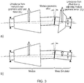
- Figure 3 shows schematically an assembly of the module and the attached mass simulator located in a balancing machine (a) with the mass body mounted to the shaft, and (b) without the mass body mounted to the shaft.
- the balancing machine is indicated by its support bearings (black triangles) at the ends of the assembly and its rotation axis (dash-dot line).
- the module's geometric error at its interface with the mass simulator produces unbalances at the module and the mass simulator indicated by respective upward-pointing arrow vectors.
- the unbalance at the simulator due to this geometric error reduces, and hence the respective vector arrow is smaller.
- the unbalance at the module from the geometric error is unchanged as this is due to the geometric error and the mass of the module.
- the assembly with the mass body mounted to the shaft ( Figure 3(a) ) is located in the balancing machine, and the total assembly unbalance due to module geometric errors is determined.
- the mass body is dismounted from the shaft ( Figure 3(b) ).
- the new assembly unbalance is detected and, taken together with the previous assembly unbalance readings, unbalance caused by the module geometric error can then be determined.
- the two assembly unbalance determinations (with mass body mounted and without mass body mounted) caused by the module geometric error can then be combined with other knowledge (i.e. rotor mode shapes) to calculate an appropriate multi-plane balance correction for the module.
- the amount of time required to make the two unbalance determinations is only increased relative to the time required to make a single unbalance determination by the time taken to dismount the mass body and establish the unbalance of the assembly without the mass body.
- No reattachment of the module to the mass simulator are needed. Additional lifting of the assembly from and into the balancing machine to mount/dismount the annular mass body may be needed, but this can be avoided if the mass body is axially slidable off the shaft onto a static holder provided on the balancing machine.
- Another option which can avoid such additional lifting is to form the mass body in portions which combine together on the shaft to form the mass body, but can be dismounted therefrom into separate pieces.
- the procedure can be performed in the opposite order, i.e. starting with the assembly without the mass body mounted to the shaft and finishing with the assembly with the mass body mounted to the shaft.
- Figure 4 shows plots of simulated vibration response against rotor speed for a rotor balanced with the dual mass simulator (circle data points) and a rotor balanced with the conventional mass simulator (diamond data points).
- the simulation shows a vibration reduction of about 70% for the dual mass simulator at a critical resonance at the indicated 1st bend mode, and significant reductions through most of the rest of the speed range
Landscapes
- Physics & Mathematics (AREA)
- General Physics & Mathematics (AREA)
- Testing Of Balance (AREA)
- Turbine Rotor Nozzle Sealing (AREA)
Applications Claiming Priority (1)
| Application Number | Priority Date | Filing Date | Title |
|---|---|---|---|
| GBGB1603759.0A GB201603759D0 (en) | 2016-03-04 | 2016-03-04 | Mass simulator and uses thereof |
Publications (1)
| Publication Number | Publication Date |
|---|---|
| EP3214421A1 true EP3214421A1 (fr) | 2017-09-06 |
Family
ID=55859000
Family Applications (1)
| Application Number | Title | Priority Date | Filing Date |
|---|---|---|---|
| EP17155779.6A Withdrawn EP3214421A1 (fr) | 2016-03-04 | 2017-02-13 | Simulateur de masse et utilisations associées |
Country Status (4)
| Country | Link |
|---|---|
| US (1) | US10274393B2 (fr) |
| EP (1) | EP3214421A1 (fr) |
| GB (1) | GB201603759D0 (fr) |
| SG (1) | SG10201701491RA (fr) |
Cited By (1)
| Publication number | Priority date | Publication date | Assignee | Title |
|---|---|---|---|---|
| EP4345248A1 (fr) * | 2022-09-30 | 2024-04-03 | Rolls-Royce plc | Masse de simulation d'équilibrage, appareil et procédés associés |
Families Citing this family (4)
| Publication number | Priority date | Publication date | Assignee | Title |
|---|---|---|---|---|
| US20180216466A1 (en) * | 2016-10-14 | 2018-08-02 | Pw Power Systems, Inc. | Methods and systems for rotating component balancing |
| GB2571707A (en) * | 2018-02-28 | 2019-09-11 | Rolls Royce Plc | Modular rotor balancing |
| US11608742B2 (en) | 2019-10-03 | 2023-03-21 | Pratt & Whitney Canada Corp. | Rotor assembly, associated method of assembly, and computer program product therefor |
| FR3159667B1 (fr) * | 2024-02-26 | 2026-01-16 | Safran Aircraft Engines | Dispositif de simulation de balourd transitoire et turbomachine équipée d’un tel dispositif |
Citations (3)
| Publication number | Priority date | Publication date | Assignee | Title |
|---|---|---|---|---|
| US6471453B1 (en) * | 2001-05-25 | 2002-10-29 | Kennametal Inc. | Balancing assembly for a rotating member |
| WO2003060452A2 (fr) * | 2002-01-14 | 2003-07-24 | Vetronix Corporation | Procede et appareil d'equilibrage de l'arbre de transmission d'un vehicule |
| EP1460287A1 (fr) * | 2003-03-18 | 2004-09-22 | Spicer Gelenkwellenbau GmbH & Co. KG | Poids d'équilibrage d'un arbre à joints de cardan |
Family Cites Families (6)
| Publication number | Priority date | Publication date | Assignee | Title |
|---|---|---|---|---|
| US3690152A (en) * | 1970-04-20 | 1972-09-12 | Walter J Hirtreiter | Method and apparatus for balancing a body about an axis |
| US3698139A (en) * | 1970-09-14 | 1972-10-17 | Warner Swasey Co | Automatic balancing device |
| US3952602A (en) * | 1971-03-03 | 1976-04-27 | Cambridge Thermionic Corporation | Rotor balancing apparatus and system |
| US4494400A (en) * | 1983-07-28 | 1985-01-22 | Fmc Corporation | Wheel balancer two plane calibration apparatus and method |
| JPH0419443A (ja) | 1990-05-15 | 1992-01-23 | Toyota Motor Corp | プロペラシャフトのバランスウェイト |
| JP6557027B2 (ja) * | 2015-02-27 | 2019-08-07 | 導啓 金濱 | 回転動力増幅装置、回転式動力発生器及び発電機 |
-
2016
- 2016-03-04 GB GBGB1603759.0A patent/GB201603759D0/en not_active Ceased
-
2017
- 2017-02-13 US US15/430,972 patent/US10274393B2/en active Active
- 2017-02-13 EP EP17155779.6A patent/EP3214421A1/fr not_active Withdrawn
- 2017-02-24 SG SG10201701491RA patent/SG10201701491RA/en unknown
Patent Citations (3)
| Publication number | Priority date | Publication date | Assignee | Title |
|---|---|---|---|---|
| US6471453B1 (en) * | 2001-05-25 | 2002-10-29 | Kennametal Inc. | Balancing assembly for a rotating member |
| WO2003060452A2 (fr) * | 2002-01-14 | 2003-07-24 | Vetronix Corporation | Procede et appareil d'equilibrage de l'arbre de transmission d'un vehicule |
| EP1460287A1 (fr) * | 2003-03-18 | 2004-09-22 | Spicer Gelenkwellenbau GmbH & Co. KG | Poids d'équilibrage d'un arbre à joints de cardan |
Cited By (4)
| Publication number | Priority date | Publication date | Assignee | Title |
|---|---|---|---|---|
| EP4345248A1 (fr) * | 2022-09-30 | 2024-04-03 | Rolls-Royce plc | Masse de simulation d'équilibrage, appareil et procédés associés |
| US20240110483A1 (en) * | 2022-09-30 | 2024-04-04 | Rolls-Royce Plc | Balancing simulation mass, apparatus and associated methods |
| GB2623065A (en) * | 2022-09-30 | 2024-04-10 | Rolls Royce Plc | Balancing simulation mass, apparatus and associated methods |
| US12442301B2 (en) * | 2022-09-30 | 2025-10-14 | Rolls-Royce Plc | Balancing simulation mass, apparatus and associated methods |
Also Published As
| Publication number | Publication date |
|---|---|
| SG10201701491RA (en) | 2017-10-30 |
| US20170254716A1 (en) | 2017-09-07 |
| GB201603759D0 (en) | 2016-04-20 |
| US10274393B2 (en) | 2019-04-30 |
Similar Documents
| Publication | Publication Date | Title |
|---|---|---|
| US10274393B2 (en) | Mass stimulator and uses thereof | |
| EP2067110B1 (fr) | Procédé et appareil pour un empilage et un équilibrage géométriques de rotor | |
| JPH0830669B2 (ja) | 回転子の釣合をとる方法 | |
| US10267703B2 (en) | Rotor balancing | |
| JP5238239B2 (ja) | ロータをバランスさせるための方法及び、回転部材を組立てる方法 | |
| RU2759651C1 (ru) | Способ и устройство для балансировки ротора | |
| JP5147001B2 (ja) | ターボ機械のロータのモジュールごとのバランス取りのための方法 | |
| CN110118632A (zh) | 借助位移传感器测量轴弹性转子的不平衡度的方法 | |
| EP1862698B1 (fr) | Correction du balourd d'un rotor | |
| CN111473859B (zh) | 整机振动限制值的制定方法 | |
| CN112105799B (zh) | 转子平衡方法和装置 | |
| US9932832B2 (en) | Method of balancing a spool of a gas turbine engine | |
| US20060272407A1 (en) | Method of calibrating the mass of components intended to be mounted at the periphery of a rotor | |
| RU2372595C1 (ru) | Способ балансировки сборного ротора | |
| JP2002221003A (ja) | ロータのバランス取り方法、その装置、およびロータ | |
| RU2426014C1 (ru) | Расчетно-имитационный способ балансировки вала | |
| RU2449180C1 (ru) | Способ балансировки ротора | |
| JP4738490B2 (ja) | 回転体のバランス調整方法 | |
| CN115541116B (zh) | 一种减小涡轮转子旋转惯性激励的控制方法 | |
| JP2011106845A (ja) | アンバランス量測定方法と装置 | |
| RU2743926C2 (ru) | Способ балансировки ротора с магнитным подвесом | |
| RU2822671C2 (ru) | Способ сборки и балансировки высокооборотных роторов и валопроводов авиационных газотурбинных двигателей и газоперекачивающих агрегатов | |
| EP4512994A2 (fr) | Module de rotor et procédé pour mettre à zéro un centre de gravité d'une pluralité d'aubes par rapport à un axe d'un disque de rotor auquel la pluralité d'aubes est fixée | |
| Tudorache et al. | Considerations Regarding the Dynamic Balancing of Complex Rotors | |
| RU2022123390A (ru) | Способ сборки и балансировки высокооборотных роторов и валопроводов авиационных газотурбинных двигателей и газоперекачивающих агрегатов |
Legal Events
| Date | Code | Title | Description |
|---|---|---|---|
| PUAI | Public reference made under article 153(3) epc to a published international application that has entered the european phase |
Free format text: ORIGINAL CODE: 0009012 |
|
| STAA | Information on the status of an ep patent application or granted ep patent |
Free format text: STATUS: THE APPLICATION HAS BEEN PUBLISHED |
|
| AK | Designated contracting states |
Kind code of ref document: A1 Designated state(s): AL AT BE BG CH CY CZ DE DK EE ES FI FR GB GR HR HU IE IS IT LI LT LU LV MC MK MT NL NO PL PT RO RS SE SI SK SM TR |
|
| AX | Request for extension of the european patent |
Extension state: BA ME |
|
| STAA | Information on the status of an ep patent application or granted ep patent |
Free format text: STATUS: REQUEST FOR EXAMINATION WAS MADE |
|
| 17P | Request for examination filed |
Effective date: 20180305 |
|
| RBV | Designated contracting states (corrected) |
Designated state(s): AL AT BE BG CH CY CZ DE DK EE ES FI FR GB GR HR HU IE IS IT LI LT LU LV MC MK MT NL NO PL PT RO RS SE SI SK SM TR |
|
| STAA | Information on the status of an ep patent application or granted ep patent |
Free format text: STATUS: EXAMINATION IS IN PROGRESS |
|
| 17Q | First examination report despatched |
Effective date: 20190517 |
|
| STAA | Information on the status of an ep patent application or granted ep patent |
Free format text: STATUS: THE APPLICATION IS DEEMED TO BE WITHDRAWN |
|
| 18D | Application deemed to be withdrawn |
Effective date: 20190828 |