EP3214473A1 - Structure de support pour un câble à fibre optique - Google Patents
Structure de support pour un câble à fibre optique Download PDFInfo
- Publication number
- EP3214473A1 EP3214473A1 EP16000504.7A EP16000504A EP3214473A1 EP 3214473 A1 EP3214473 A1 EP 3214473A1 EP 16000504 A EP16000504 A EP 16000504A EP 3214473 A1 EP3214473 A1 EP 3214473A1
- Authority
- EP
- European Patent Office
- Prior art keywords
- support structure
- optical fiber
- hollow
- support element
- fiber cable
- Prior art date
- Legal status (The legal status is an assumption and is not a legal conclusion. Google has not performed a legal analysis and makes no representation as to the accuracy of the status listed.)
- Granted
Links
Images


Classifications
-
- G—PHYSICS
- G02—OPTICS
- G02B—OPTICAL ELEMENTS, SYSTEMS OR APPARATUS
- G02B6/00—Light guides; Structural details of arrangements comprising light guides and other optical elements, e.g. couplings
- G02B6/44—Mechanical structures for providing tensile strength and external protection for fibres, e.g. optical transmission cables
- G02B6/4401—Optical cables
- G02B6/4429—Means specially adapted for strengthening or protecting the cables
- G02B6/443—Protective covering
- G02B6/4432—Protective covering with fibre reinforcements
- G02B6/4433—Double reinforcement laying in straight line with optical transmission element
-
- G—PHYSICS
- G02—OPTICS
- G02B—OPTICAL ELEMENTS, SYSTEMS OR APPARATUS
- G02B6/00—Light guides; Structural details of arrangements comprising light guides and other optical elements, e.g. couplings
- G02B6/44—Mechanical structures for providing tensile strength and external protection for fibres, e.g. optical transmission cables
- G02B6/4401—Optical cables
- G02B6/4429—Means specially adapted for strengthening or protecting the cables
- G02B6/4435—Corrugated mantle
-
- G—PHYSICS
- G02—OPTICS
- G02B—OPTICAL ELEMENTS, SYSTEMS OR APPARATUS
- G02B6/00—Light guides; Structural details of arrangements comprising light guides and other optical elements, e.g. couplings
- G02B6/44—Mechanical structures for providing tensile strength and external protection for fibres, e.g. optical transmission cables
- G02B6/4439—Auxiliary devices
- G02B6/4471—Terminating devices ; Cable clamps
- G02B6/44785—Cable clamps
-
- G—PHYSICS
- G02—OPTICS
- G02B—OPTICAL ELEMENTS, SYSTEMS OR APPARATUS
- G02B6/00—Light guides; Structural details of arrangements comprising light guides and other optical elements, e.g. couplings
- G02B6/46—Processes or apparatus adapted for installing or repairing optical fibres or optical cables
- G02B6/48—Overhead installation
- G02B6/483—Installation of aerial type
-
- H—ELECTRICITY
- H02—GENERATION; CONVERSION OR DISTRIBUTION OF ELECTRIC POWER
- H02G—INSTALLATION OF ELECTRIC CABLES OR LINES, OR OF COMBINED OPTICAL AND ELECTRIC CABLES OR LINES
- H02G7/00—Overhead installations of electric lines or cables
- H02G7/05—Suspension arrangements or devices for electric cables or lines
- H02G7/053—Suspension clamps and clips for electric overhead lines not suspended to a supporting wire
Definitions
- the invention relates to the field of communication cables, and, more particularly, to a support structure for an aerial optical fiber cable.
- Communication cables employing optical fibers are widely used in the telecommunications industry.
- multifiber cables are widely used for long distance telephone communications, interexchange telephone applications, and other telephony and data transmission applications.
- Fiber optic cables are also being incorporated into cable television networks in place of more traditional coaxial cables.
- Optical fibers may permit long distanced between signal repeaters or eliminate the need for such repeaters altogether.
- optical fibers offer extremely wide bandwidths and low noise operation.
- a traditional used embodiment of fiber optic cables in telecom industry are the so called ADSS (A11-Dielectric Self Supporting) cables. They typically include one central element surrounded by several fiber protecting tubes named “loose tube”, since the internal diameter of these protective tubes are several times bigger than the diameter of the group of inserted fibers. There is an internal cable sheath placed around the group of loose tubes. Aramid layers are placed between the inner and an outer cable sheath. This aramid layers ensure the necessary tensile strength for the cable to be applicable for aerial implementations.
- FIG. 8 Another traditional aerial optical cable type, which has been used for trunk and backbone network applications for a long time is the so called "figure 8" type cable, which consists of a central element, surrounded by fiber protecting loose tubes. Around the loose tubes is a. single cable sheath placed. This cable sheath is extruded together with a support element forming a single physical unit.
- the support element wire can be steel wire, rope or made from dielectric material like FRP (Fiber Reinforced Plastic). This support element wire (rope) ensures the necessary tensile strength for the cable and makes it applicable for aerial networks.
- the object of the invention is provided with a support structure for an optical fiber cable adapted to be aerially installed in a configuration extending generally horizontally along a series of spaced apart vertical pilots, said support structure comprising:
- the support element may preferably be composed of high-density polyethylene with several additives, and may have the form of a square with rounded edges, a hollow space in the center and a lateral opening on one corner of the square.
- the surface of the hollow of the support structure shows longitudinal ribs.
- At least one of the longitudinal strength members can be made of fiber reinforced plastic material.
- two longitudinal strength members are extending along respective opposite sides of the hollow.
- the size of the lateral opening of the hollow may be in the range of 65% - 70 % of the outside diameter of the optical fiber cable which has to be incorporated and the diameter of the hollow may be in the range of 125% to 150% of the optical fiber cables outside diameter.
- the inventive support structure is intended to be used in the aerial part of an optical fiber communication network.
- a fiber optic cable 7 has to be aerially installed along a series of vertical supports or poles 1.
- Tt has to resist the forces of nature, in particular the loads of wind or ice.
- this problem can be solved by using a support structure, which gives the optical fiber cable the required strength, but simplifies the handling.
- the support structure is secured to the end poles of the aerial network line by as shown in fig. 2 .
- the usage of anchoring frames is also recommended at those places, where aerial installation crosses roads or an corners of the line, that is to say, when deviation from the straight line exceeds 10 degrees.
- Fig. 4 shows a part of an inventive support element 2. It is composed of high-density polyethylene with several additives, which ensure resistance and reduce friction coefficient of the material.
- Its cross section has approximately the form of a "C”, in other words, it has the form of a square with rounded edges, a hollow space 3 in the center and a lateral opening 4 on one corner of the square.
- the surface of the hollow 3 shows longitudinal ribs 5.
- a pair of longitudinal strength members 6 extending along respective opposite sides of the hollow 3 is incorporated in its body.
- the symmetrical design is an important feature of the support element 2; it helps to maitain the straight form of the extruded element during manufacturing and during the cooling and crystallization process.
- the longitudinal ribs 5 in the surface of the hollow 3 ensure lower dragging forces for pulling the inserted cable 7 by reducing friction surfaces.
- the physical size of the support element 2 is determined by the outside diameter of the applied optical fiber cable /. There are two critical parameters. One is the size of lateral opening 4 of the hollow 3, which should be in the range of 65% - 70 % of the outside diameter of the cable 7.
- the second critical parameter is the diameter of the hollow 3, which should be between 125% and 150% of the cables 7 outside diameter.
- the outer dimension of the support element 2 is derived from these parameters and the necessary wall thickness to reach the pre-defined values for the stability of the element.
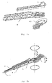
- the anchoring frame for attaching the support element to vertical poles comprises three major components; a frame body 8 which guides the support element 2 with some hook-like forms at each side; a support element 2 specific clamping wedge 9 with a bottom surface which has the negative form of the upper part of the support element 2, so it fits perfectly to the support element 2 when the clamping wedge 9 is inserted into the body 8 of the anchoring frame right over the support clement 2.
- the way of insertion during an installation process is from the front to the back of the frame body B. While the clamping wedge 9 is moved backward, hooks at the side press the clamping wedge down towards the support element 2 until the desired clamp force is reached.
- the third basic component of the anchoring frame is a bridging arm 10, which connects the frame body 8 to a pole 1.
- Fig 2b shows the anchoring frame in a mounted stale.
- the inventive system allows different movements of the support element 2 but not twisting. So the opening of the support element 2 will always face upward.
- the application of the anchoring frame is only recommended at certain poles 1.
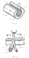
- On the other poles 1, holding bracket as shown in fig.3a in a separated state and in fig. 3b in a mounted state arc used for attachment.
- Theses holding brackets comprise 3 components, a bracket base 11 and two turnable side plates 12 .
- the side plates 12 are identical to each other, any of them can be used aL the left or right side as well.
- Fig. 3b shows the mounted holding bracket with the support structure 2 and the optical fiber cable 7 inside.
- the installation process comprises the following steps:
- the cable 7 is pressed through the lateral opening 4 into the hollow 3 of the support element 2 by help of some rollers 13, 14.
- a first type of rollers 13 is designed to position and hold the support element 2 in a fixed position while a second type of rollers 14 presses the cable 7 into the support element 2.
Landscapes
- Physics & Mathematics (AREA)
- General Physics & Mathematics (AREA)
- Optics & Photonics (AREA)
- Light Guides In General And Applications Therefor (AREA)
Priority Applications (3)
| Application Number | Priority Date | Filing Date | Title |
|---|---|---|---|
| EP16000504.7A EP3214473B1 (fr) | 2016-03-02 | 2016-03-02 | Structure de support pour un câble à fibre optique |
| US16/098,553 US10488614B2 (en) | 2016-03-02 | 2017-02-27 | Support structure for an optical fiber cable |
| PCT/EP2017/000266 WO2017148580A1 (fr) | 2016-03-02 | 2017-02-27 | Structure de support pour un câble à fibres optiques |
Applications Claiming Priority (1)
| Application Number | Priority Date | Filing Date | Title |
|---|---|---|---|
| EP16000504.7A EP3214473B1 (fr) | 2016-03-02 | 2016-03-02 | Structure de support pour un câble à fibre optique |
Publications (3)
| Publication Number | Publication Date |
|---|---|
| EP3214473A1 true EP3214473A1 (fr) | 2017-09-06 |
| EP3214473B1 EP3214473B1 (fr) | 2023-08-30 |
| EP3214473C0 EP3214473C0 (fr) | 2023-08-30 |
Family
ID=55456547
Family Applications (1)
| Application Number | Title | Priority Date | Filing Date |
|---|---|---|---|
| EP16000504.7A Active EP3214473B1 (fr) | 2016-03-02 | 2016-03-02 | Structure de support pour un câble à fibre optique |
Country Status (3)
| Country | Link |
|---|---|
| US (1) | US10488614B2 (fr) |
| EP (1) | EP3214473B1 (fr) |
| WO (1) | WO2017148580A1 (fr) |
Cited By (1)
| Publication number | Priority date | Publication date | Assignee | Title |
|---|---|---|---|---|
| US10488614B2 (en) | 2016-03-02 | 2019-11-26 | Ing3 Beteiligungs Gmbh | Support structure for an optical fiber cable |
Families Citing this family (1)
| Publication number | Priority date | Publication date | Assignee | Title |
|---|---|---|---|---|
| CN118444447B (zh) * | 2024-07-08 | 2024-09-13 | 深圳市爱迪讯通信科技有限公司 | 一种便于安装的自承式室内光缆及其安装方法 |
Citations (4)
| Publication number | Priority date | Publication date | Assignee | Title |
|---|---|---|---|---|
| US5678609A (en) * | 1995-03-06 | 1997-10-21 | Arnco Corporation | Aerial duct with ribbed liner |
| JP2008129168A (ja) * | 2006-11-17 | 2008-06-05 | Advanced Cable Systems Corp | 光ファイバケーブル |
| GB2470284B (en) * | 2009-05-14 | 2014-05-14 | Draka Comteq Bv | Aerial signal conductor holder |
| GB2515628A (en) * | 2013-05-20 | 2014-12-31 | A 2 Sea Solutions Ltd | Armoured cable |
Family Cites Families (2)
| Publication number | Priority date | Publication date | Assignee | Title |
|---|---|---|---|---|
| US7202418B2 (en) * | 2004-01-07 | 2007-04-10 | Cable Components Group, Llc | Flame retardant and smoke suppressant composite high performance support-separators and conduit tubes |
| EP3214473B1 (fr) | 2016-03-02 | 2023-08-30 | ING3 Beteiligungs GmbH | Structure de support pour un câble à fibre optique |
-
2016
- 2016-03-02 EP EP16000504.7A patent/EP3214473B1/fr active Active
-
2017
- 2017-02-27 WO PCT/EP2017/000266 patent/WO2017148580A1/fr not_active Ceased
- 2017-02-27 US US16/098,553 patent/US10488614B2/en active Active
Patent Citations (4)
| Publication number | Priority date | Publication date | Assignee | Title |
|---|---|---|---|---|
| US5678609A (en) * | 1995-03-06 | 1997-10-21 | Arnco Corporation | Aerial duct with ribbed liner |
| JP2008129168A (ja) * | 2006-11-17 | 2008-06-05 | Advanced Cable Systems Corp | 光ファイバケーブル |
| GB2470284B (en) * | 2009-05-14 | 2014-05-14 | Draka Comteq Bv | Aerial signal conductor holder |
| GB2515628A (en) * | 2013-05-20 | 2014-12-31 | A 2 Sea Solutions Ltd | Armoured cable |
Cited By (1)
| Publication number | Priority date | Publication date | Assignee | Title |
|---|---|---|---|---|
| US10488614B2 (en) | 2016-03-02 | 2019-11-26 | Ing3 Beteiligungs Gmbh | Support structure for an optical fiber cable |
Also Published As
| Publication number | Publication date |
|---|---|
| WO2017148580A1 (fr) | 2017-09-08 |
| EP3214473B1 (fr) | 2023-08-30 |
| EP3214473C0 (fr) | 2023-08-30 |
| US20190146173A1 (en) | 2019-05-16 |
| US10488614B2 (en) | 2019-11-26 |
Similar Documents
| Publication | Publication Date | Title |
|---|---|---|
| EP1557707B1 (fr) | Bobine de couplage d'un tube de protection et procédé d'installation d'un cable à fibres optiques | |
| US6101305A (en) | Fiber optic cable | |
| US6185351B1 (en) | All-dielectric, self-supporting, loose-tube cable with optical fiber ribbons | |
| US6628880B2 (en) | Fiber optic cable splice enclosure | |
| JP2005510027A5 (fr) | ||
| US8620128B2 (en) | System and method for anchoring fiber optic cables to provide strain relief | |
| US20090290844A1 (en) | Tap-off closure systems and methods for using the same | |
| EP4243228A2 (fr) | Dispositifs serre-câbles à soulagement de traction et procédés d'utilisation correspondants | |
| US6836603B1 (en) | Optical fiber cables | |
| EP2920631B1 (fr) | Tube de bifurcation robuste | |
| EP0616696A1 (fr) | Gainage pour fibre optique | |
| WO2013142453A1 (fr) | Appareil et procédé pour un épissage de câble à fibres optiques autoportant tout diélectrique | |
| US20100239215A1 (en) | Methods for Terminating Optical Fiber Cables | |
| CA2499794A1 (fr) | Systeme retractable de raccordement d'ames multiples | |
| WO2011160297A1 (fr) | Coffret de fibres optiques | |
| US10488614B2 (en) | Support structure for an optical fiber cable | |
| CN213482531U (zh) | 一种可扩展的多芯蝶形引入光缆 | |
| EP3011377A1 (fr) | Conducteur bobiné et câble composite optique/électrique comprenant un ensemble conducteur bobiné | |
| EP3916455A1 (fr) | Soulagement de contrainte de fibre optique et ensembles associés | |
| EP3764143A2 (fr) | Fibre optique améliorée et conception de transition de puissance | |
| WO2018139999A1 (fr) | Câbles de distribution de fibres optiques renforcées à diamètre réduit | |
| WO2016025937A1 (fr) | Appareil pour contenir un câble | |
| CN107250865A (zh) | 混合光纤带和电力电缆 | |
| DE19838351C2 (de) | Optisches Kabel und Kabelanordnung | |
| CN115542485B (zh) | 一种s型骨架式光缆及其制备方法 |
Legal Events
| Date | Code | Title | Description |
|---|---|---|---|
| PUAI | Public reference made under article 153(3) epc to a published international application that has entered the european phase |
Free format text: ORIGINAL CODE: 0009012 |
|
| STAA | Information on the status of an ep patent application or granted ep patent |
Free format text: STATUS: THE APPLICATION HAS BEEN PUBLISHED |
|
| AK | Designated contracting states |
Kind code of ref document: A1 Designated state(s): AL AT BE BG CH CY CZ DE DK EE ES FI FR GB GR HR HU IE IS IT LI LT LU LV MC MK MT NL NO PL PT RO RS SE SI SK SM TR |
|
| AX | Request for extension of the european patent |
Extension state: BA ME |
|
| STAA | Information on the status of an ep patent application or granted ep patent |
Free format text: STATUS: REQUEST FOR EXAMINATION WAS MADE |
|
| 17P | Request for examination filed |
Effective date: 20180228 |
|
| RBV | Designated contracting states (corrected) |
Designated state(s): AL AT BE BG CH CY CZ DE DK EE ES FI FR GB GR HR HU IE IS IT LI LT LU LV MC MK MT NL NO PL PT RO RS SE SI SK SM TR |
|
| R17P | Request for examination filed (corrected) |
Effective date: 20180228 |
|
| STAA | Information on the status of an ep patent application or granted ep patent |
Free format text: STATUS: EXAMINATION IS IN PROGRESS |
|
| 17Q | First examination report despatched |
Effective date: 20220128 |
|
| GRAP | Despatch of communication of intention to grant a patent |
Free format text: ORIGINAL CODE: EPIDOSNIGR1 |
|
| STAA | Information on the status of an ep patent application or granted ep patent |
Free format text: STATUS: GRANT OF PATENT IS INTENDED |
|
| INTG | Intention to grant announced |
Effective date: 20230417 |
|
| GRAS | Grant fee paid |
Free format text: ORIGINAL CODE: EPIDOSNIGR3 |
|
| GRAA | (expected) grant |
Free format text: ORIGINAL CODE: 0009210 |
|
| STAA | Information on the status of an ep patent application or granted ep patent |
Free format text: STATUS: THE PATENT HAS BEEN GRANTED |
|
| AK | Designated contracting states |
Kind code of ref document: B1 Designated state(s): AL AT BE BG CH CY CZ DE DK EE ES FI FR GB GR HR HU IE IS IT LI LT LU LV MC MK MT NL NO PL PT RO RS SE SI SK SM TR |
|
| REG | Reference to a national code |
Ref country code: GB Ref legal event code: FG4D |
|
| REG | Reference to a national code |
Ref country code: CH Ref legal event code: EP |
|
| REG | Reference to a national code |
Ref country code: DE Ref legal event code: R096 Ref document number: 602016082249 Country of ref document: DE |
|
| REG | Reference to a national code |
Ref country code: IE Ref legal event code: FG4D |
|
| U01 | Request for unitary effect filed |
Effective date: 20230925 |
|
| U07 | Unitary effect registered |
Designated state(s): AT BE BG DE DK EE FI FR IT LT LU LV MT NL PT SE SI Effective date: 20230929 |
|
| PG25 | Lapsed in a contracting state [announced via postgrant information from national office to epo] |
Ref country code: GR Free format text: LAPSE BECAUSE OF FAILURE TO SUBMIT A TRANSLATION OF THE DESCRIPTION OR TO PAY THE FEE WITHIN THE PRESCRIBED TIME-LIMIT Effective date: 20231201 |
|
| PG25 | Lapsed in a contracting state [announced via postgrant information from national office to epo] |
Ref country code: IS Free format text: LAPSE BECAUSE OF FAILURE TO SUBMIT A TRANSLATION OF THE DESCRIPTION OR TO PAY THE FEE WITHIN THE PRESCRIBED TIME-LIMIT Effective date: 20231230 |
|
| PG25 | Lapsed in a contracting state [announced via postgrant information from national office to epo] |
Ref country code: RS Free format text: LAPSE BECAUSE OF FAILURE TO SUBMIT A TRANSLATION OF THE DESCRIPTION OR TO PAY THE FEE WITHIN THE PRESCRIBED TIME-LIMIT Effective date: 20230830 Ref country code: NO Free format text: LAPSE BECAUSE OF FAILURE TO SUBMIT A TRANSLATION OF THE DESCRIPTION OR TO PAY THE FEE WITHIN THE PRESCRIBED TIME-LIMIT Effective date: 20231130 Ref country code: IS Free format text: LAPSE BECAUSE OF FAILURE TO SUBMIT A TRANSLATION OF THE DESCRIPTION OR TO PAY THE FEE WITHIN THE PRESCRIBED TIME-LIMIT Effective date: 20231230 Ref country code: HR Free format text: LAPSE BECAUSE OF FAILURE TO SUBMIT A TRANSLATION OF THE DESCRIPTION OR TO PAY THE FEE WITHIN THE PRESCRIBED TIME-LIMIT Effective date: 20230830 Ref country code: GR Free format text: LAPSE BECAUSE OF FAILURE TO SUBMIT A TRANSLATION OF THE DESCRIPTION OR TO PAY THE FEE WITHIN THE PRESCRIBED TIME-LIMIT Effective date: 20231201 |
|
| PG25 | Lapsed in a contracting state [announced via postgrant information from national office to epo] |
Ref country code: PL Free format text: LAPSE BECAUSE OF FAILURE TO SUBMIT A TRANSLATION OF THE DESCRIPTION OR TO PAY THE FEE WITHIN THE PRESCRIBED TIME-LIMIT Effective date: 20230830 |
|
| PG25 | Lapsed in a contracting state [announced via postgrant information from national office to epo] |
Ref country code: ES Free format text: LAPSE BECAUSE OF FAILURE TO SUBMIT A TRANSLATION OF THE DESCRIPTION OR TO PAY THE FEE WITHIN THE PRESCRIBED TIME-LIMIT Effective date: 20230830 |
|
| PG25 | Lapsed in a contracting state [announced via postgrant information from national office to epo] |
Ref country code: SM Free format text: LAPSE BECAUSE OF FAILURE TO SUBMIT A TRANSLATION OF THE DESCRIPTION OR TO PAY THE FEE WITHIN THE PRESCRIBED TIME-LIMIT Effective date: 20230830 Ref country code: RO Free format text: LAPSE BECAUSE OF FAILURE TO SUBMIT A TRANSLATION OF THE DESCRIPTION OR TO PAY THE FEE WITHIN THE PRESCRIBED TIME-LIMIT Effective date: 20230830 Ref country code: ES Free format text: LAPSE BECAUSE OF FAILURE TO SUBMIT A TRANSLATION OF THE DESCRIPTION OR TO PAY THE FEE WITHIN THE PRESCRIBED TIME-LIMIT Effective date: 20230830 Ref country code: CZ Free format text: LAPSE BECAUSE OF FAILURE TO SUBMIT A TRANSLATION OF THE DESCRIPTION OR TO PAY THE FEE WITHIN THE PRESCRIBED TIME-LIMIT Effective date: 20230830 Ref country code: SK Free format text: LAPSE BECAUSE OF FAILURE TO SUBMIT A TRANSLATION OF THE DESCRIPTION OR TO PAY THE FEE WITHIN THE PRESCRIBED TIME-LIMIT Effective date: 20230830 |
|
| U20 | Renewal fee for the european patent with unitary effect paid |
Year of fee payment: 9 Effective date: 20240325 |
|
| REG | Reference to a national code |
Ref country code: DE Ref legal event code: R097 Ref document number: 602016082249 Country of ref document: DE |
|
| PLBE | No opposition filed within time limit |
Free format text: ORIGINAL CODE: 0009261 |
|
| STAA | Information on the status of an ep patent application or granted ep patent |
Free format text: STATUS: NO OPPOSITION FILED WITHIN TIME LIMIT |
|
| 26N | No opposition filed |
Effective date: 20240603 |
|
| REG | Reference to a national code |
Ref country code: CH Ref legal event code: PL |
|
| PG25 | Lapsed in a contracting state [announced via postgrant information from national office to epo] |
Ref country code: MC Free format text: LAPSE BECAUSE OF FAILURE TO SUBMIT A TRANSLATION OF THE DESCRIPTION OR TO PAY THE FEE WITHIN THE PRESCRIBED TIME-LIMIT Effective date: 20230830 |
|
| GBPC | Gb: european patent ceased through non-payment of renewal fee |
Effective date: 20240302 |
|
| PG25 | Lapsed in a contracting state [announced via postgrant information from national office to epo] |
Ref country code: MC Free format text: LAPSE BECAUSE OF FAILURE TO SUBMIT A TRANSLATION OF THE DESCRIPTION OR TO PAY THE FEE WITHIN THE PRESCRIBED TIME-LIMIT Effective date: 20230830 |
|
| PG25 | Lapsed in a contracting state [announced via postgrant information from national office to epo] |
Ref country code: GB Free format text: LAPSE BECAUSE OF NON-PAYMENT OF DUE FEES Effective date: 20240302 |
|
| PG25 | Lapsed in a contracting state [announced via postgrant information from national office to epo] |
Ref country code: IE Free format text: LAPSE BECAUSE OF NON-PAYMENT OF DUE FEES Effective date: 20240302 |
|
| PG25 | Lapsed in a contracting state [announced via postgrant information from national office to epo] |
Ref country code: IE Free format text: LAPSE BECAUSE OF NON-PAYMENT OF DUE FEES Effective date: 20240302 Ref country code: GB Free format text: LAPSE BECAUSE OF NON-PAYMENT OF DUE FEES Effective date: 20240302 Ref country code: CH Free format text: LAPSE BECAUSE OF NON-PAYMENT OF DUE FEES Effective date: 20240331 |
|
| U20 | Renewal fee for the european patent with unitary effect paid |
Year of fee payment: 10 Effective date: 20250325 |
|
| PG25 | Lapsed in a contracting state [announced via postgrant information from national office to epo] |
Ref country code: CY Free format text: LAPSE BECAUSE OF FAILURE TO SUBMIT A TRANSLATION OF THE DESCRIPTION OR TO PAY THE FEE WITHIN THE PRESCRIBED TIME-LIMIT; INVALID AB INITIO Effective date: 20160302 |
|
| PG25 | Lapsed in a contracting state [announced via postgrant information from national office to epo] |
Ref country code: HU Free format text: LAPSE BECAUSE OF FAILURE TO SUBMIT A TRANSLATION OF THE DESCRIPTION OR TO PAY THE FEE WITHIN THE PRESCRIBED TIME-LIMIT; INVALID AB INITIO Effective date: 20160302 |
|
| PG25 | Lapsed in a contracting state [announced via postgrant information from national office to epo] |
Ref country code: TR Free format text: LAPSE BECAUSE OF FAILURE TO SUBMIT A TRANSLATION OF THE DESCRIPTION OR TO PAY THE FEE WITHIN THE PRESCRIBED TIME-LIMIT Effective date: 20230830 |