EP3214524B1 - Dispositif de commande, système de commande, dispositif d'analyse, dispositif de tri de particules, procédé de commande, et programme de régulation de flux laminaire - Google Patents
Dispositif de commande, système de commande, dispositif d'analyse, dispositif de tri de particules, procédé de commande, et programme de régulation de flux laminaire Download PDFInfo
- Publication number
- EP3214524B1 EP3214524B1 EP15854482.5A EP15854482A EP3214524B1 EP 3214524 B1 EP3214524 B1 EP 3214524B1 EP 15854482 A EP15854482 A EP 15854482A EP 3214524 B1 EP3214524 B1 EP 3214524B1
- Authority
- EP
- European Patent Office
- Prior art keywords
- control
- air pressure
- water pressure
- fluid
- pressure measurement
- Prior art date
- Legal status (The legal status is an assumption and is not a legal conclusion. Google has not performed a legal analysis and makes no representation as to the accuracy of the status listed.)
- Active
Links
Images





Classifications
-
- G—PHYSICS
- G05—CONTROLLING; REGULATING
- G05D—SYSTEMS FOR CONTROLLING OR REGULATING NON-ELECTRIC VARIABLES
- G05D7/00—Control of flow
- G05D7/06—Control of flow characterised by the use of electric means
- G05D7/0617—Control of flow characterised by the use of electric means specially adapted for fluid materials
-
- G—PHYSICS
- G01—MEASURING; TESTING
- G01N—INVESTIGATING OR ANALYSING MATERIALS BY DETERMINING THEIR CHEMICAL OR PHYSICAL PROPERTIES
- G01N15/00—Investigating characteristics of particles; Investigating permeability, pore-volume or surface-area of porous materials
- G01N15/10—Investigating individual particles
- G01N15/14—Optical investigation techniques, e.g. flow cytometry
-
- G—PHYSICS
- G01—MEASURING; TESTING
- G01N—INVESTIGATING OR ANALYSING MATERIALS BY DETERMINING THEIR CHEMICAL OR PHYSICAL PROPERTIES
- G01N15/00—Investigating characteristics of particles; Investigating permeability, pore-volume or surface-area of porous materials
- G01N15/10—Investigating individual particles
- G01N15/14—Optical investigation techniques, e.g. flow cytometry
- G01N15/1404—Handling flow, e.g. hydrodynamic focusing
-
- G—PHYSICS
- G01—MEASURING; TESTING
- G01N—INVESTIGATING OR ANALYSING MATERIALS BY DETERMINING THEIR CHEMICAL OR PHYSICAL PROPERTIES
- G01N15/00—Investigating characteristics of particles; Investigating permeability, pore-volume or surface-area of porous materials
- G01N15/10—Investigating individual particles
- G01N15/14—Optical investigation techniques, e.g. flow cytometry
- G01N15/1456—Optical investigation techniques, e.g. flow cytometry without spatial resolution of the texture or inner structure of the particle, e.g. processing of pulse signals
- G01N15/1459—Optical investigation techniques, e.g. flow cytometry without spatial resolution of the texture or inner structure of the particle, e.g. processing of pulse signals the analysis being performed on a sample stream
-
- G—PHYSICS
- G05—CONTROLLING; REGULATING
- G05D—SYSTEMS FOR CONTROLLING OR REGULATING NON-ELECTRIC VARIABLES
- G05D7/00—Control of flow
- G05D7/06—Control of flow characterised by the use of electric means
-
- G—PHYSICS
- G01—MEASURING; TESTING
- G01N—INVESTIGATING OR ANALYSING MATERIALS BY DETERMINING THEIR CHEMICAL OR PHYSICAL PROPERTIES
- G01N15/00—Investigating characteristics of particles; Investigating permeability, pore-volume or surface-area of porous materials
- G01N15/02—Investigating particle size or size distribution
- G01N15/0205—Investigating particle size or size distribution by optical means
-
- G—PHYSICS
- G01—MEASURING; TESTING
- G01N—INVESTIGATING OR ANALYSING MATERIALS BY DETERMINING THEIR CHEMICAL OR PHYSICAL PROPERTIES
- G01N15/00—Investigating characteristics of particles; Investigating permeability, pore-volume or surface-area of porous materials
- G01N15/10—Investigating individual particles
- G01N15/14—Optical investigation techniques, e.g. flow cytometry
- G01N15/1404—Handling flow, e.g. hydrodynamic focusing
- G01N15/1409—Handling samples, e.g. injecting samples
-
- G—PHYSICS
- G01—MEASURING; TESTING
- G01N—INVESTIGATING OR ANALYSING MATERIALS BY DETERMINING THEIR CHEMICAL OR PHYSICAL PROPERTIES
- G01N15/00—Investigating characteristics of particles; Investigating permeability, pore-volume or surface-area of porous materials
- G01N15/10—Investigating individual particles
- G01N15/14—Optical investigation techniques, e.g. flow cytometry
- G01N15/149—Optical investigation techniques, e.g. flow cytometry specially adapted for sorting particles, e.g. by their size or optical properties
-
- G—PHYSICS
- G01—MEASURING; TESTING
- G01N—INVESTIGATING OR ANALYSING MATERIALS BY DETERMINING THEIR CHEMICAL OR PHYSICAL PROPERTIES
- G01N15/00—Investigating characteristics of particles; Investigating permeability, pore-volume or surface-area of porous materials
- G01N15/02—Investigating particle size or size distribution
- G01N2015/0288—Sorting the particles
-
- G—PHYSICS
- G01—MEASURING; TESTING
- G01N—INVESTIGATING OR ANALYSING MATERIALS BY DETERMINING THEIR CHEMICAL OR PHYSICAL PROPERTIES
- G01N15/00—Investigating characteristics of particles; Investigating permeability, pore-volume or surface-area of porous materials
- G01N15/02—Investigating particle size or size distribution
- G01N2015/0294—Particle shape
-
- G—PHYSICS
- G01—MEASURING; TESTING
- G01N—INVESTIGATING OR ANALYSING MATERIALS BY DETERMINING THEIR CHEMICAL OR PHYSICAL PROPERTIES
- G01N15/00—Investigating characteristics of particles; Investigating permeability, pore-volume or surface-area of porous materials
- G01N15/10—Investigating individual particles
- G01N15/14—Optical investigation techniques, e.g. flow cytometry
- G01N2015/1493—Particle size
-
- G—PHYSICS
- G01—MEASURING; TESTING
- G01N—INVESTIGATING OR ANALYSING MATERIALS BY DETERMINING THEIR CHEMICAL OR PHYSICAL PROPERTIES
- G01N15/00—Investigating characteristics of particles; Investigating permeability, pore-volume or surface-area of porous materials
- G01N15/10—Investigating individual particles
- G01N15/14—Optical investigation techniques, e.g. flow cytometry
- G01N2015/1497—Particle shape
Definitions
- the present technology relates to a control apparatus for controlling a flow velocity of a laminar flow, and more particularly, to a control apparatus, a control system, an analysis apparatus, a particle separation/collection apparatus, a control method, and a laminar flow control program each for controlling a flow velocity of a laminar flow, for use in analysis, separation/collection, and/or the like, of microparticles etc. contained in the laminar flow.
- microparticles such as biological microparticles (including cells and microorganisms), microbeads, and/or the like
- flow cytometry an analysis technique called flow cytometry is being rapidly improved in technology.
- Flow cytometry is an analysis technique that analyzes and separates/collects microparticles by introducing analyte microparticles into a fluid in a linear arrangement, irradiating the microparticles with laser light or the like, and thus detecting fluorescence and/or scattered light emitted from each of the microparticles .
- a process of flow cytometry can be broadly grouped into: (1) water flow part, (2) optical part, (3) electrical/analytical part, and (4) separation/collection part described above.
- analyte microparticles are arranged in a linear arrangement in a flow cell (flow channel) . More specifically, a sheath flow is introduced into the flow cell at a constant flow velocity, in which condition a sample flow containing the microparticles is gently introduced into a center portion of the flow cell. In this situation, the flows do not mix with each other due to the principle of laminar flow, and thus a flow arranged in layers (laminar flow) is formed. The inflows of the sheath flow and of the sample flow are then adjusted on the basis of the sizes etc. of the analyte microparticles to transport each of the microparticles therethrough in a linear arrangement.
- analyte microparticles are irradiated with light, such as laser, and fluorescence and/or scattered light emitted from the microparticles is detected.
- the microparticles are transported through a laser irradiation portion while each being arranged in a linear arrangement, and each time one microparticle passes therethrough, fluorescence and/or scattered light emitted from that microparticle is detected using an optical detector on a per-parameter basis to analyze characteristics of the individual microparticles.
- optical information detected in the optical part is converted into an electrical signal (voltage pulse).
- the electrical signal generated by conversion is digitized by analog-to-digital conversion, and a histogram is computed from the resulting data for analysis, using an analyzing computer and software.
- the microparticles that have undergone measurement are separated and collected.
- One representative method of separation/collection is a method including positively or negatively charging the microparticles that have undergone measurement, interposing the flow cell between two deflection plates having a potential difference therebetween, and allowing the electrically charged microparticles to be attracted toward one of the deflection plates depending on the electric charge thereof, thereby to perform separation/collection.
- a technology for analyzing and separating/collecting microparticles in a flow channel is widely used in various fields, such as medical, drug discovery, clinical examination, food, agricultural, engineering, forensic medicine, criminal identification fields. Particularly in the medical field, such a technology plays an important role in pathology, tumor immunology, transplantation medicine, genetics, regenerative medicine, chemotherapy, and the like.
- Patent Document 1 discloses a technology for controlling a flow velocity of a sheath fluid by providing a pressure sensor in a flow channel of the sheath fluid, and by changing a value of the pressure exerted on the sheath fluid on the basis of the water pressure sensed by the pressure sensor.
- Patent Document 1 Japanese Patent Application Laid-Open No. 64-88251
- a microparticle sorting device is described in WO2014/115409 which is capable of stabilizing sorting performance over a prolonged period of time.
- control of the flow velocity of the laminar flow is highly important partly for improving accuracy in analysis and in separation/collection.
- control of a flow velocity of a laminar flow has been provided by changing a value of the pressure exerted on the fluid on the basis of a water pressure of the fluid.
- pressurization to a fluid first increases a pressure in a vessel that contains the fluid, and thus it takes time to achieve an increase in the water pressure of the fluid that will be discharged from the vessel through the flow channel. Therefore, a problem exists in that feedback control based on the water pressure of a fluid may cause the pressure to overshoot.
- a less amount of the fluid in the vessel requires more time for the vessel to be filled with air, which in turn requires still more time to achieve an increase in the water pressure of the fluid that will be discharged from the vessel through the flow channel. This will cause the pressure to further overshoot.
- a problem exists in that a significant time is required for the water pressure of the fluid to be stabilized at a desired value.
- control based on an air pressure that pressurizes the fluid is incapable of taking into consideration the amount of the fluid in the vessel or a change in water viscosity caused by a temperature change. This poses a problem in that highly responsive control cannot be provided.
- the present inventors have conducted intensive studies to achieve the foregoing object, and by having regard to the characteristics of air pressure-based control and of water pressure-based control, the present inventors have been successful in reducing the time required for control by providing switching of the control. Thus, the present technology has been developed.
- the present technology first provides a control apparatus for controlling a flow velocity of a laminar flow, the apparatus including:
- control unit may be configured to provide switching from control based on the air pressure measured by the air pressure measurement unit to control based on the water pressure measured by the water pressure measurement unit.
- the timing of the switching in the control unit is not particularly limited. However, switching may be performed from the control based on the air pressure measured by the air pressure measurement unit to the control based on the water pressure measured by the water pressure measurement unit after stabilization of the air pressure measured by the air pressure measurement unit.
- control unit may be configured to provide switching from the control based on the air pressure measured by the air pressure measurement unit to the control based on the water pressure measured by the water pressure measurement unit, at one or more time points selected from the time points (a) to (c):
- the laminar flow controllable by the control apparatus according to the present technology is nor particularly limited.
- the laminar flow may be formed of a sample flow containing a sample, and of a sheath flow surrounding the sample flow, and the fluid may be a sheath fluid that is to form the sheath flow.
- the control unit may also be configured to determine whether to switch from the control based on the air pressure measured by the air pressure measurement unit to the control based on the water pressure measured by the water pressure measurement unit by determining in order from (1) to (3) :
- the present technology secondly provides a control system for controlling a flow velocity of a laminar flow, the system including:
- At least a part of the apparatuses may be connected to each other via a network.
- the present technology further provides an analysis apparatus for analyzing a particle in a laminar flow formed of a sample flow containing the particle, and of a sheath flow surrounding the sample flow, the analysis apparatus comprising a control apparatus according to claim 1 wherein the fluid is a sheath fluid to form the sheath flow.
- the present technology further provides a particle separation and collection apparatus for separating and collecting a particle in a laminar flow formed of a sample flow containing the particle, and of a sheath flow surrounding the sample flow, the particle separation and collection apparatus comprising a control apparatus according to claim 1 wherein the fluid is a sheath fluid that is to from the sheath flow.
- the present technology additionally provides a laminar flow control method for controlling a flow velocity of a laminar flow, the method including:
- the present technology further provides a laminar flow control program used for controlling a flow velocity of a laminar flow, and for causing a computer to perform:
- particle encompasses all that can pass through a sample flow, including biologically relevant microparticles, such as cells, microorganisms, liposomes, DNAs, and proteins; and synthetic particles, such as latex particles, gel particles, and industrial particles.
- the time required for the flow velocity of the laminar flow to stabilize can be reduced, and more finely responsive control of the laminar flow can be provided.
- Fig. 1 is a conceptual schematic diagram schematically illustrating a first embodiment of a control apparatus 1 according to the present technology.
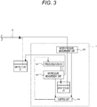
- the control apparatus 1 according to the present technology is a control apparatus for controlling a flow velocity of a laminar flow, and includes at least, in terms of broad groupings, a pressurization unit 11, an air pressure measurement unit 12, a water pressure measurement unit 13, and a control unit 14. Each of these units will be hereinafter described in detail. Note that although Fig. 1 and after-mentioned Figs. 3 and 4 show a flow channel P for purposes of illustration, the flow channel P is not included in the control apparatus 1 according to the present technology.
- pressurization unit 11 a pressure is applied to a fluid F that is to form a laminar flow.
- the method of pressurization in the pressurization unit 11 is not particularly limited, and any publicly known pressurization method may be arbitrarily selected and used.
- pressurization may be performed by supplying compressed air into the vessel that contains the fluid using a compressed air source, such as a compressor, and an electro-pneumatic regulator and the like, and/or by other method.
- a publicly known pressure meter may be arbitrarily selected and used in the air measurement unit 12 of the control apparatus 1 according to the present technology.
- water pressure measurement unit 13 measurement is made of the water pressure of the fluid F pressurized by the pressurization unit 11.
- a publicly known water pressure meter may be arbitrarily selected and used in the water pressure measurement unit 13 of the control apparatus 1 according to the present technology.
- control of the pressure force applied to the fluid F by the pressurization unit 11 is provided on the basis of either the air pressure measured by the air pressure measurement unit 12, or the water pressure measured by the water pressure measurement unit 13.
- the control apparatus 1 is characterized in that switching is performed in this control unit 14 between control based on the air pressure measured by the air pressure measurement unit 12 (hereinafter also referred to simply as “air pressure-based control”) and control based on the water pressure measured by the water pressure measurement unit 13 (hereinafter also referred to simply as “water pressure-based control”).
- air pressure-based control control based on the air pressure measured by the air pressure measurement unit 12
- water pressure-based control water pressure-based control
- Appropriately switching between the air pressure-based control and the water pressure-based control depending on the situation can reduce the time required for the flow velocity of the laminar flow to stabilize, and provide more finely responsive control that takes into consideration the amount of the fluid in the vessel and a change in water viscosity caused by a temperature change.
- the direction of the switching in the control unit may be changed according to the purpose as appropriate.
- the switching may be in a direction from the air pressure-based control to the water pressure-based control, or in a direction from the water pressure-based control to the air pressure-based control.
- switching may thus be performed as many times as needed according to the situation and/or the purpose; e.g., switching may be performed such that the air pressure-based control is switched to the water pressure-based control, and then the control may further be switched back to the air pressure-based control.
- the present technology prefers, in particular, that air pressure-based control be performed in an early stage of forming a laminar flow, and then the control be switched to water pressure-based control.
- Performing air pressure-based control in an early stage can reduce the time required for the flow velocity of the laminar flow to stabilize, and switching thereafter to water pressure-based control can provide more finely responsive control that takes into consideration the amount of the fluid in the vessel and a change in water viscosity caused by a temperature change.
- the timing of switching from air pressure-based control to water pressure-based control is nor particularly limited, and may be appropriately set depending on the situation.
- the present technology prefers, in particular, that switching be performed from air pressure-based control to water pressure-based control after the air pressure measured by the air pressure measurement unit 12 stabilizes. Once the air pressure has stabilized, the pressure is very unlikely to overshoot even if the control is switched to the water pressure-based control. Thus, the time required to stabilize the fluid to a desired water pressure can be more effectively reduced.
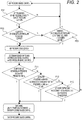
- Fig. 2 is a flowchart illustrating one example of the timing of switching from air pressure-based control to water pressure-based control in the control apparatus 1 according to the present technology.
- the air pressure measurement unit 12 monitors the pressure applied to the fluid F, and the control unit 14 starts air pressure-based control.
- stability of the air pressure monitored by the air pressure measurement unit 12 is determined.
- the method for determining stability of the air pressure is not particularly limited. Examples thereof include a method including determining that stability is reached when the air pressure measured falls within a specific range relative to a target air pressure, and a specific amount of time has elapsed since the air pressure measured has fallen within the range of the target air pressure.
- Fig. 2 illustrates one example of determining that stability is reached if a condition of target air pressure ⁇ 0.5 kPa has lasted for 5 seconds. More specifically, if the air pressure measured falls within a range of target air pressure ⁇ 0.5 kPa (hereinafter also referred to as “stable air pressure range") (see “P01" in Fig. 2 ), measurement of the duration time of continued stable air pressure is started (see “P02" in Fig. 2 ); and when 5 seconds has elapsed, the process proceeds to determination of switching from air pressure-based control to water pressure-based control.
- stable air pressure range a range of target air pressure ⁇ 0.5 kPa
- the process waits for a specific period of time until the elapsed time in the stable air pressure range reaches 5 seconds (see "P03" in Fig. 2 ); and when the elapsed time in the stable air pressure range reaches 5 seconds, the process proceeds to determination of switching from air pressure-based control to water pressure-based control. If the specific period of time expires before the elapsed time in the stable air pressure range reaches 5 seconds, the air pressure-based control is performed again, and thus the process returns to the determination of air pressure stability of P01. This process continues until the air pressure stabilizes.
- a differential pressure between the air pressure measured by the air pressure measurement unit 12 and the water pressure measured by the water pressure measurement unit 13 has reached a predetermined value or below (see "P11" in Fig. 2) .
- Fig. 2 shows an example in which it is determined that switching can be performed if the difference between the air pressure and the water pressure is below 10 kPa.
- Fig. 2 shows an example in which it is determined that switching can be performed if the average of deviation of the water pressure during a time period of 6400 ms is below 0.3 kPa.
- Fig. 2 shows an example in which switching is performed without condition when 90 seconds has elapsed since the air pressure has stabilized.
- control unit of the control apparatus 1 performs hierarchical determination and determination based on timer expiration as appropriate, and thus achieves reduction in the time required for the flow velocity of the laminar flow to stabilize.
- Fig. 3 is a conceptual schematic diagram schematically illustrating with a second embodiment of the control apparatus 1 according to the present technology.
- the second embodiment shown in Fig. 3 is an example of using the control apparatus 1 according to the present technology for controlling the flow velocity of a sheath flow F2, in a laminar flow formed of a sample flow F1 containing a sample and of the sheath flow F2 surrounding the sample flow F1.
- the control apparatus 1 is capable of controlling the flow velocities of both the sample flow F1 and the sheath flow F2, but is preferably used, in particular, for controlling the flow velocity of the sheath flow F2.
- the reason is as follows: the amount of the sample flow F1 is often less than the amount of the sheath flow F2; thus, the flow velocity of the sample flow F1 is relatively easy to control, and is therefore often controllable without using a special control technology such as the control apparatus 1 according to the present technology.
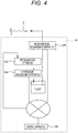
- Fig. 4 is a conceptual schematic diagram schematically illustrating a first embodiment of a control system 10 according to the present technology.
- the control system 10 according to the present technology is a control system for controlling a flow velocity of a laminar flow, and includes at least, in terms of broad groupings, a pressurization apparatus 110, an air pressure measurement apparatus 120, a water pressure measurement apparatus 130, and a control apparatus 140.
- a pressurization apparatus 110 the air pressure measurement apparatus 120, the water pressure measurement apparatus 130, and the control apparatus 140 are the same, respectively, as those described above for the pressurization unit 11, the air pressure measurement unit 12, the water pressure measurement unit 13, and the control unit 14 of the control apparatus 1 according to the present technology, and explanation thereof is thus omitted here.
- a part or all of the apparatuses may be connected to each other via a network.
- control apparatus 1 and the control system 10 according to the present technology can each be suitably used as a control mechanism in an analysis apparatus for analyzing a particle S in a laminar flow, or in a particle separation/collection apparatus for separating/collecting a particle S in a laminar flow.
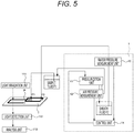
- Fig. 5 is a conceptual schematic diagram schematically illustrating a first embodiment of an analysis apparatus according to the present technology.
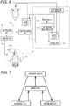
- Fig. 6 is a conceptual schematic diagram schematically illustrating a first embodiment of a particle separation/collection apparatus according to the present technology.
- the control apparatus 1 used in the analysis apparatus shown in Fig. 5 , and used in the particle separation/collection apparatus shown in Fig. 6 is the same as that described above, and explanation thereof is thus omitted here.
- the analysis apparatus and the particle separation/collection apparatus may include various functions commonly included in a publicly known analysis apparatus and particle separation/collection apparatus (such as what is called flow cytometer) and the like. Specifically, a light irradiation unit 111, a light detection unit 112, an analysis unit 113, a separation/collection unit 121, and the like may be included. In addition, a flow channel P may also be provided as needed. Each of these units will be hereinafter described in detail.
- the flow channel P may be originally provided in the analysis apparatus and the particle separation/collection apparatus according to the present technology; or otherwise, a commercially available flow channel P or disposable chip having a flow channel P may be placed in the analysis apparatus and in the particle separation/collection apparatus for performing analysis or separation/collection.
- a flow channel P usable in the analysis apparatus and in the particle separation/collection apparatus according to the present technology is not particularly limited, and may be arbitrarily designed.
- it is not limited to the flow channel P formed in a two- or three-dimensional substrate T formed of plastic or glass as shown in the analysis apparatus of Fig. 5 , but as shown in the particle separation/collection apparatus of Fig. 6 , a flow channel P such as one used in a conventional flow cytometer may also be used in the analysis apparatus and in the particle separation/collection apparatus according to the present technology.
- the flow channel width, the flow channel depth, and the flow channel cross-sectional shape of the flow channel P described above are not particularly limited as long as that form allows a laminar flow to be formed, and may be arbitrarily designed.
- a micro-flow channel having a flow channel width of 1 mm or less may also be used in the analysis apparatus and in the particle separation/collection apparatus according to the present technology.
- a micro-flow channel having a flow channel width of about 10 ⁇ m or more and about 1 mm or less can be suitably used by the analysis apparatus and the particle separation/collection apparatus according to the present technology.
- the bottom of the flow channel P is preferably formed of a transparent material. As shown in the analysis apparatus of Fig. 5 , the purpose of this is to allow optical information from the bottom side of the flow channel P to be detected by disposing a light detection unit 112 described below on an opposite side of the substrate T from the light irradiation unit 111 described below.
- the light irradiation unit 111 In the light irradiation unit 111, light is emitted to a particle S that is passing through the flow channel P.
- the type of the light emitted from the light irradiation unit 111 is not particularly limited. However, in order to ensure that the particle S emits fluorescence and/or scattered light, the light preferably has a constant light direction, a constant wavelength, and a constant light intensity. Examples thereof include a laser, an LED, and the like.
- the type of the laser if used, is nor particularly limited, an argon ion (Ar) laser, a helium-neon (He-Ne) laser, a dye laser, a krypton (Cr) laser, a semiconductor laser, a solid-state laser having a semiconductor laser and a wavelength conversion optical element in combination, or the like, or an arbitrary combination of two or more thereof may be used.
- the light detection unit 112 detects optical information provided by the particle S caused by light irradiation by the light irradiation unit 111.
- the type of the light detection unit 112 usable in the present technology is not particularly limited as long as the optical information can be detected, and any publicly known light detector may be arbitrarily selected and used.
- the installation location of the light detection unit 112 each in the analysis apparatus and in the particle separation/collection apparatus according to the present technology is not particularly limited as long as the optical information provided by the particle S can be detected, and can be arbitrarily designed.
- the installation location is preferably on an opposite side of the flow channel P from the light irradiation unit 111 as shown in Figs. 5 and 6 . This is because disposing the light detection unit 112 on an opposite side of the flow channel P from the light irradiation unit 111 permits the light irradiation unit 111 and the light detection unit 112 to be disposed in a more flexible configuration.
- the installation location may be on the same side of the flow channel P as the light irradiation unit 111, or on a side of the flow channel P at 90 degrees with respect to the light irradiation unit 111.
- the particle S is analyzed on the basis of the optical information provided by the particle S, detected by the light detection unit 112.
- This analysis unit 113 is not essential to the analysis apparatus and to the particle separation/collection apparatus according to the present technology, but properties etc. of the particle S may be analyzed on the basis of the optical information detected by the light detection unit 112, by using an external analysis apparatus or the like.
- the particle S is separated/collected on the basis of the optical information detected by the light detection unit 112, or of an analysis result of the particle S analyzed in the analysis unit 113.
- the particle S can be separated/collected on the basis of analysis results of the size, the form, the internal structure, and/or the like of the particle S analyzed using the optical information at a location downstream of the flow channel P.
- oscillation is applied, for example, to a part or to the entirety of the flow channel P using a vibration element 121a that oscillates at a predetermined frequency to generate droplets from the outlet of the flow channel P.
- the vibration element 121a used in this situation is not particularly limited, and any publicly known one may be arbitrarily selected and used. Examples thereof include a piezo vibration element.
- the size of the droplets can be adjusted to form droplets that each include a fixed amount of the sample.
- the droplets formed are positively or negatively charged on the basis of the analysis results of the size, the form, the internal structure, and/or the like of the particles S analyzed (see those indicated by the symbol 121b in Fig. 6 ) .
- the electrically charged droplets are then directed to travel in a desired direction by counter electrodes 121c with a voltage being applied thereacross, and the droplets are thus separated/collected.
- Fig. 7 is a flow diagram of a control method according to the present technology.
- the control method according to the present technology is a control method for controlling a flow velocity of a laminar flow, and is a method that performs at least, in terms of broad groupings, a pressurization step I, an air pressure measurement step II, a water pressure measurement step III, and a control step IV.
- a pressurization step I an air pressure measurement step II
- a water pressure measurement step III a control step IV.
- the details of the pressurization step I, the air pressure measurement step II, the water pressure measurement step III, and the control step IV are the same, respectively, as those described above for the methods performed by the pressurization unit 11, the air pressure measurement unit 12, the water pressure measurement unit 13, and the control unit 14 of the control apparatus 1 according to the present technology, and explanation thereof is thus omitted here.
- control method according to the present technology described above can be suitably used as a laminar flow control method in an analysis method for analyzing the particle S in the laminar flow, and/or in a particle separation/collection method for separating/collecting the particle S in the laminar flow.
- Fig. 8 is a flow diagram of an analysis method according to the present technology
- Fig. 9 is a flow diagram of a particle separation/collection method according to the present technology.
- the pressurization step I, the air pressure measurement step II, the water pressure measurement step III, and the control step IV performed in the analysis method shown in Fig. 8 and in the particle separation/collection method shown in Fig. 9 are the same as those described above, and explanation thereof is thus omitted here.
- the analysis method and the particle separation/collection method according to the present technology may include various steps commonly performed in a publicly known analysis method and particle separation/collection method (such as what is called flow cytometry) and the like. Specifically, a transport step V, a light irradiation step VI, a light detection step VII, an analysis step VIII, a separation/collection step IX, and the like may be performed.
- the details of the light irradiation step VI, the light detection step VII, the analysis step VIII, and the separation/collection step IX are the same, respectively, as those described above for the methods performed by the light irradiation unit 111, the light detection unit 112, the analysis unit 113, and the separation/collection unit 121 of the analysis apparatus and of the particle separation/collection apparatus according to the present technology, and explanation thereof is thus omitted here.
- the transport step V is a step of transporting the particle S through the laminar flow.
- the method for transporting the particle S through the laminar flow is not particularly limited. Examples thereof may include a method including transportation with the sample flow F1 containing the particle S being sandwiched by a fluid medium (sheath flow F2) that facilitates straightening as shown in Figs. 5 and 6 . Transportation in such a manner can form a laminar flow of the sample flow F1 containing the particle S, and is thus more suitable.
- the type of the fluid medium (sheath flow F2) is not particularly limited as long as the fluid medium has a capability of facilitating straightening of the sample flow F1 containing the particle S. For example, if the particle S is a cell, a physiological saline solution or the like may be used.
- the particle S is preferably modified with a labeling substance such as a fluorescent substance (e.g., a fluorescent pigment), a radioactive substance, an intercalator, or a microbead so that optical information will be detectable in the light detection step VII.
- a labeling substance such as a fluorescent substance (e.g., a fluorescent pigment), a radioactive substance, an intercalator, or a microbead so that optical information will be detectable in the light detection step VII.
- a fluorescent substance e.g., a fluorescent pigment
- radioactive substance e.g., an intercalator, or a microbead
- Cascade Blue for example, Cascade Blue, Pacific Blue, fluorescein isothiocyanate (FITC), phycoerythrin (PE), propidium iodide (PI), Texas Red (TR), peridinin-chlorophyll-protein (PerCP), allophycocyanin (APC), 4',6-diamidino-2-phenylindole (DAPI), Cy3, Cy5, Cy7, or the like, or an arbitrary combination of two or more thereof may be used.
- FITC fluorescein isothiocyanate
- PE phycoerythrin
- PI propidium iodide
- TR Texas Red
- PerCP peridinin-chlorophyll-protein
- APC allophycocyanin
- DAPI 4',6-diamidino-2-phenylindole
- Cy3, Cy5, Cy7, or the like or an arbitrary combination of two or more thereof
- the particle S emits light in itself as does a fluorescent protein, no need exists for modification with a labeling substance. Also, no need exists for modifying the particle S with a labeling substance if a substance is used for the particle S, which substance can, for example, change the fluorescence color of that substance and/or the like as taught in the principle of FRET, by promoting interaction between substances in the flow channel P.
- An analysis program is a laminar flow control program used for controlling a flow velocity of a laminar flow, and is a program for causing a computer to perform a first control function, a second control function, and a switching control function. Each of these functions will be hereinafter described in detail.
- the first control function controls the pressure force applied to the fluid on the basis of the air pressure applied to the fluid that is to form the laminar flow.
- the second control function controls the pressure force applied to the fluid on the basis of water pressure of the fluid that is to form the laminar flow.
- the switching control function provides switching between performance of the first control function and performance of the second control function.
- the details of the switching control function are the same as those described above for the switching between air pressure-based control and water pressure-based control provided by the control unit 14 of the control apparatus 1 described above, and explanation thereof is thus omitted here.
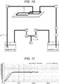
- Fig. 10 is a conceptual schematic diagram schematically illustrating an apparatus used in Experimental Examples 1 to 3.
- the symbol "a" indicates a compressor serving as a compressed air source.
- An air tube b connected to this compressor "a” branches into a pressure-regulating regulator c for the sheath fluid and a pressure-regulating regulator d for the sample fluid.
- the pressure-regulating regulator c for the sheath fluid is connected to a sheath fluid vessel f (capacity: 10 L) for storing the sheath fluid, with an air pressure sensor e for measuring the pressure applied on the sheath fluid interposed therebetween.
- the pressure-regulating regulator d for the sample fluid is connected to a sample fluid vessel h, with an air pressure sensor g for measuring the pressure applied on the sample fluid interposed therebetween.
- a sheath nozzle i is immersed in the sheath fluid in the sheath fluid vessel f, and is directed into a chip-type flow cell m, with a water pressure sensor (liquid pressure meter) j and sheath fluid inlet control valves k, 1 interposed therebetween.
- a sample nozzle n is immersed in the sample fluid in the sample fluid vessel h, and a sample tube o connected to the sample nozzle n is directed into the chip-type flow cell m, with a sample fluid inlet valve p interposed therebetween.
- the sheath fluid vessel f of the apparatus described above was charged with 10.9 kg of the sheath fluid, in which condition the pressure applied to the sheath fluid was adjusted only on the basis of the output of the water pressure sensor j, and feedback control was thus provided to the flow velocity of the sheath fluid. More specifically, control was started under a non-pressurized condition (-8 kPa to -5 kPa), and was provided until the flow velocity of the sheath flow stabilized at 10 m/s (water pressure: about 158.0 kPa). During the control, the air pressure and the water pressure were monitored using the air pressure sensor e and the water pressure sensor j.
- Control was provided in the same manner as in Experimental Example 1 except that the sheath fluid vessel f was charged with 2.5 kg of the sheath fluid.
- Fig. 11 The changes in the air pressure and in the water pressure in Reference Example 1 are shown in Fig. 11 ; and the changes in the air pressure and in the water pressure in Reference Example 2 are shown in Fig. 12 .
- Fig. 11 when the sheath fluid vessel f was almost completely filled with the sheath fluid, the flow velocity stabilized in about 60 seconds.
- Fig. 12 it has been found that when the amount of the sheath fluid in the sheath fluid vessel f is low, a time lag occurs between the increase of the water pressure and the increase of the air pressure.
- both the air pressure and the water pressure exhibited overshoot, and it took 180 seconds or more for the flow velocity to stabilize.
- the sheath fluid vessel f of the apparatus described above was charged with 2.5 kg of the sheath fluid, in which condition the pressure applied to the sheath fluid was adjusted on the basis of the output of the air pressure sensor e, and feedback control was thus provided to the flow velocity of the sheath fluid; and the pressure applied to the sheath fluid was then adjusted on the basis of the output of the water pressure sensor j, and feedback control was thus provided to the flow velocity of the sheath fluid.
- control was started under a non-pressurized condition (-8 kPa to -5 kPa), which control was based on the output of the air pressure sensor e; and when the differential pressure between the air pressure and the water pressure reaches a value less than 10 kPa, the control was switched to the control based on the output of the water pressure sensor j, and the control was thereafter continued until the flow velocity of the sheath flow stabilized at 10 m/s (water pressure: about 158.0 kPa). During the control, the air pressure and the water pressure were monitored using the air pressure sensor e and the water pressure sensor j.
- Example 1 in which switching was performed from the air pressure-based control to the water pressure-based control, had the result that even when the amount of the sheath fluid in the sheath fluid vessel f is low, neither the air pressure nor the water pressure exhibited overshoot, and the flow velocity stabilized in about 120 seconds.
- Example 3 an examination was made of differences between the times required for the flow velocity of the sheath flow to stabilize when the pressure force applied to the sheath fluid was controlled only on the basis of the water pressure of the sheath flow, and when switching was performed from air pressure-based control to water pressure-based control in a similar manner to Example 2, each under a condition that the sheath fluid vessel f was almost completely filled with the sheath fluid, with different target flow velocities of the sheath flow.
- the sheath fluid vessel f of the apparatus described above was charged with 10.9 kg of the sheath fluid, in which condition the pressure applied to the sheath fluid was adjusted on the basis of the output of the air pressure sensor e, and feedback control was thus provided to the flow velocity of the sheath fluid; and the pressure applied to the sheath fluid was then adjusted on the basis of the output of the water pressure sensor j, and feedback control was thus provided to the flow velocity of the sheath fluid.
- control was started under a non-pressurized condition (-8 kPa to -5 kPa), which control was based on the output of the air pressure sensor e; and when the differential pressure between the air pressure and the water pressure reaches a value less than 10 kPa, the control was switched to the control based on the output of the water pressure sensor j, and the control was thereafter continued until the flow velocity of the sheath flow stabilized at 3 m/s (water pressure: about 33.0 kPa). During the control, the air pressure and the water pressure were monitored using the air pressure sensor e and the water pressure sensor j.
- Control was provided in a similar manner to Example 2 except that the control was provided until the flow velocity of the sheath flow stabilized at 5 m/s (water pressure: about 62.0 kPa).
- Control was provided in a similar manner to Example 2 except that the control was provided until the flow velocity of the sheath flow stabilized at 10 m/s (water pressure: about 150.0 kPa).
- Control was provided in a similar manner to Example 2 except that the sheath fluid vessel f of the apparatus described above was charged with 2.7 kg of the sheath fluid.
- Control was provided in a similar manner to Example 3 except that the sheath fluid vessel f of the apparatus described above was charged with 2.7 kg of the sheath fluid.
- Control was provided in a similar manner to Example 4 except that the sheath fluid vessel f of the apparatus described above was charged with 2.7 kg of the sheath fluid.
- the sheath fluid vessel f of the apparatus described above was charged with 10.9 kg of the sheath fluid, in which condition the pressure applied to the sheath fluid was adjusted only on the basis of the output of the water pressure sensor j, and feedback control was thus provided to the flow velocity of the sheath fluid. More specifically, control was started under a non-pressurized condition (-8 kPa to -5 kPa), and was provided until the flow velocity of the sheath flow stabilized at 3 m/s (water pressure: about 33.0 kPa). During the control, the air pressure and the water pressure were monitored using the air pressure sensor e and the water pressure sensor j.
- Control was provided in a similar manner to Comparative Example 2 except that the control was provided until the flow velocity of the sheath flow stabilized at 5 m/s (water pressure : about 62.0 kPa).
- Control was provided in a similar manner to Comparative Example 2 except that the control was provided until the flow velocity of the sheath flow stabilized at 10 m/s (water pressure: about 150.0 kPa).
- Control was provided in a similar manner to Comparative Example 2 except that the sheath fluid vessel f of the apparatus described above was charged with 2.7 kg of the sheath fluid.
- Control was provided in a similar manner to Comparative Example 3 except that the sheath fluid vessel f of the apparatus described above was charged with 2.7 kg of the sheath fluid.
- Control was provided in a similar manner to Comparative Example 4 except that the sheath fluid vessel f of the apparatus described above was charged with 2.7 kg of the sheath fluid.
Landscapes
- Chemical & Material Sciences (AREA)
- General Physics & Mathematics (AREA)
- Physics & Mathematics (AREA)
- Biochemistry (AREA)
- Life Sciences & Earth Sciences (AREA)
- Analytical Chemistry (AREA)
- Health & Medical Sciences (AREA)
- General Health & Medical Sciences (AREA)
- Dispersion Chemistry (AREA)
- Immunology (AREA)
- Pathology (AREA)
- Engineering & Computer Science (AREA)
- Automation & Control Theory (AREA)
- Sampling And Sample Adjustment (AREA)
- Flow Control (AREA)
Claims (12)
- Appareil de commande servant à réguler une vitesse d'écoulement d'un écoulement laminaire, l'appareil comprenant :une unité de mise sous pression (11) configurée pour mettre sous pression un fluide qui est destiné à former l'écoulement laminaire ;une unité de mesure de pression d'air (12) configurée pour mesurer une pression appliquée au fluide par l'unité de mise sous pression ;une unité de mesure de pression d'eau (13) configurée pour mesurer une pression d'eau du fluide mis sous pression par l'unité de mise sous pression ; etune unité de commande (14) configurée pour commander la force de pression appliquée au fluide par l'unité de mise sous pression sur la base soit de la pression d'air mesurée par l'unité de mesure de pression d'air soit de la pression d'eau mesurée par l'unité de mesure de pression d'eau,dans lequel l'unité de commande est configurée pour produire une commutation entre la commande basée sur la pression d'air mesurée par l'unité de mesure de pression d'air et de la commande basée sur la pression d'eau mesurée par l'unité de mesure de pression d'eau.
- Appareil de commande selon la revendication 1,
dans lequel l'unité de commande est configurée pour produire la commutation de la commande basée sur la pression d'air mesurée par l'unité de mesure de pression d'air à la commande basée sur la pression d'eau mesurée par l'unité de mesure de pression d'eau. - Appareil de commande selon la revendication 2,
dans lequel l'unité de commande est configurée pour produire la commutation de la commande basée sur la pression d'air mesurée par l'unité de mesure de pression d'air à la commande basée sur la pression d'eau mesurée par l'unité de mesure de pression d'eau après la stabilisation de la pression d'air mesurée par l'unité de mesure de pression d'air. - Appareil de commande selon la revendication 2,
dans lequel l'unité de commande est configurée pour produire la commutation de la commande basée sur la pression d'air mesurée par l'unité de mesure de pression d'air à la commande basée sur la pression d'eau mesurée par l'unité de mesure de pression d'eau à un ou plusieurs points temporels sélectionnés parmi (a) à (c) :(a) lorsqu'une pression différentielle entre la pression d'air mesurée par l'unité de mesure de pression d'air et la pression d'eau mesurée par l'unité de mesure de pression d'eau atteint une valeur prédéfinie ou est inférieure à celle-ci,(b) lorsqu'une quantité de variation de la pression d'eau mesurée par l'unité de mesure de pression d'eau atteint une valeur prédéfinie ou est inférieure à celle-ci et(c) lorsqu'une durée de la commande basée sur la pression d'air mesurée par l'unité de mesure de pression d'air dépasse un laps de temps prédéfini. - Appareil de commande selon la revendication 1,
dans lequel l'écoulement laminaire est formé à partir d'un écoulement d'échantillon contenant un échantillon, et d'un écoulement de gaine entourant l'écoulement d'échantillon, et le fluide est un fluide de gaine qui est destiné à former l'écoulement de gaine. - Appareil de commande selon la revendication 4,
dans lequel l'unité de commande est configurée pour déterminer s'il faut commuter de la commande basée sur la pression d'air mesurée par l'unité de mesure de pression d'air à la commande basée sur la pression d'eau mesurée par l'unité de mesure de pression d'eau en déterminant, dans l'ordre de (1) à (3) :(1) si la pression différentielle entre la pression d'air mesurée par l'unité de mesure de pression d'air et la pression d'eau mesurée par l'unité de mesure de pression d'eau a atteint la valeur prédéfinie ou est inférieure à celle-ci,(2) si la quantité de variation de la pression d'eau mesurée par l'unité de mesure de pression d'eau a atteint la valeur prédéfinie ou est inférieure à celle-ci et(3) si la durée de la commande basée sur la pression d'air mesurée par l'unité de mesure de pression d'air a dépassé le laps de temps prédéfini. - Système de commande servant à réguler une vitesse d'écoulement d'un écoulement laminaire, le système comprenant :un appareil de mise sous pression (110) configuré pour mettre sous pression un fluide qui est destiné à former l'écoulement laminaire ;un appareil de mesure de pression d'air (120) configuré pour mesurer une pression appliquée au fluide par l'appareil de mise sous pression ;un appareil de mesure de pression d'eau (130) configuré pour mesurer une pression d'eau du fluide mis sous pression par l'unité de mise sous pression ; etun appareil de commande (140) configuré pour commander la force de pression appliquée au fluide par l'appareil de mise sous pression sur la base soit de la pression d'air mesurée par l'appareil de mesure de pression d'air soit de la pression d'eau mesurée par l'appareil de mesure de pression d'eau,dans lequel l'appareil de commande est configuré pour produire une commutation entre la commande basée sur la pression d'air mesurée par l'appareil de mesure de pression d'air et la commande basée sur la pression d'eau mesurée par l'appareil de mesure de pression d'eau.
- Système de commande selon la revendication 7, dans lequel au moins une partie des appareils sont connectés les uns aux autres par le biais d'un réseau.
- Appareil d'analyse servant à analyser une particule dans un écoulement laminaire formé à partir d'un écoulement d'échantillon contenant la particule, et d'un écoulement de gaine entourant l'écoulement d'échantillon, l'appareil d'analyse comprenant un appareil de commande selon la revendication 1, dans lequel le fluide est un fluide de gaine qui est destiné à former l'écoulement de gaine.
- Appareil de séparation et de collecte de particule servant à séparer et collecter une particule dans un écoulement laminaire formé à partir d'un écoulement d'échantillon contenant la particule, et d'un écoulement de gaine entourant l'écoulement d'échantillon, l'appareil de séparation et de collecte de particule comprenant un appareil de commande selon la revendication 1, dans lequel le fluide est un fluide de gaine qui est destiné à former l'écoulement de gaine.
- Procédé de régulation d'écoulement laminaire permettant de réguler une vitesse d'écoulement d'un écoulement laminaire, le procédé comprenant :une étape de mise sous pression consistant à mettre sous pression un fluide qui est destiné à former l'écoulement laminaire ;une étape de mesure de pression d'air consistant à mesurer une pression appliquée au fluide dans l'étape de mise sous pression ;une étape de mesure de pression d'eau consistant à mesurer une pression d'eau du fluide mis sous pression dans l'étape de mise sous pression ; etune étape de commande consistant à commander la force de pression appliquée au fluide dans l'étape de mise sous pression sur la base soit de la pression d'air mesurée dans l'étape de mesure de pression d'air soit de la pression d'eau mesurée dans l'étape de mesure de pression d'eau,dans lequel l'étape de commande comprend la commutation entre la commande basée sur la pression d'air mesurée dans l'étape de mesure de pression d'air et la commande basée sur la pression d'eau mesurée dans l'étape de mesure de pression d'eau.
- Programme de régulation d'écoulement laminaire utilisé pour réguler une vitesse d'écoulement d'un écoulement laminaire, et pour amener un ordinateur à effectuer :une première fonction de commande qui commande la force de pression appliquée au fluide, sur la base d'une pression d'air appliquée à un fluide qui est destiné à former l'écoulement laminaire ;une deuxième fonction de commande qui commande la force de pression appliquée au fluide, sur la base d'une pression d'eau du fluide qui est destiné à former l'écoulement laminaire ; etune fonction de commande de commutation qui produit la commutation entre la réalisation de la première fonction de commande et la réalisation de la deuxième fonction de commande.
Applications Claiming Priority (2)
| Application Number | Priority Date | Filing Date | Title |
|---|---|---|---|
| JP2014221035 | 2014-10-30 | ||
| PCT/JP2015/075966 WO2016067772A1 (fr) | 2014-10-30 | 2015-09-14 | Dispositif de commande, système de commande, dispositif d'analyse, dispositif de tri de particules, procédé de commande, et programme de régulation de flux laminaire |
Publications (3)
| Publication Number | Publication Date |
|---|---|
| EP3214524A1 EP3214524A1 (fr) | 2017-09-06 |
| EP3214524A4 EP3214524A4 (fr) | 2018-07-18 |
| EP3214524B1 true EP3214524B1 (fr) | 2019-08-07 |
Family
ID=55857118
Family Applications (1)
| Application Number | Title | Priority Date | Filing Date |
|---|---|---|---|
| EP15854482.5A Active EP3214524B1 (fr) | 2014-10-30 | 2015-09-14 | Dispositif de commande, système de commande, dispositif d'analyse, dispositif de tri de particules, procédé de commande, et programme de régulation de flux laminaire |
Country Status (4)
| Country | Link |
|---|---|
| US (1) | US10670509B2 (fr) |
| EP (1) | EP3214524B1 (fr) |
| JP (1) | JP6801453B2 (fr) |
| WO (1) | WO2016067772A1 (fr) |
Families Citing this family (3)
| Publication number | Priority date | Publication date | Assignee | Title |
|---|---|---|---|---|
| JP7063683B2 (ja) * | 2018-03-30 | 2022-05-09 | シスメックス株式会社 | フローサイトメーター及び粒子検出方法 |
| CN110813703A (zh) * | 2019-11-27 | 2020-02-21 | 福建工程学院 | 一种滚筒式土体颗粒分析试验装置 |
| EP3947970B1 (fr) * | 2020-05-19 | 2024-03-20 | Life Technologies Corporation | Système fluidique à deux étages avec pulsation réduite |
Family Cites Families (8)
| Publication number | Priority date | Publication date | Assignee | Title |
|---|---|---|---|---|
| EP0046345A3 (fr) * | 1980-08-15 | 1982-03-03 | Ortho Diagnostic Systems Inc. | Dispositif d'écoulement hydrodynamique contrôlé dans un système cytométrique à écoulement |
| US5245318A (en) | 1987-07-24 | 1993-09-14 | Canon Kabushiki Kaisha | Particle analyzing apparatus having pressure control system |
| JPS6488251A (en) | 1987-09-30 | 1989-04-03 | Canon Kk | Particle analyzer |
| JPH0498305A (ja) | 1990-08-10 | 1992-03-31 | Fueroo Kogyo Kk | 粉・粒体制御システム |
| US6767188B2 (en) * | 2002-08-15 | 2004-07-27 | Becton, Dickinson And Company | Constant output fluidic system |
| WO2013192401A1 (fr) * | 2012-06-22 | 2013-12-27 | Bio-Rad Laboratories, Inc. | Système de mélange de liquides et de rinçage pour cytomètre à flux |
| EP2894459A4 (fr) * | 2012-09-06 | 2016-04-27 | Furukawa Electric Co Ltd | Dispositif d'identification et de distribution d'échantillons et procédé d'identification et de distribution d'échantillons |
| WO2014115409A1 (fr) * | 2013-01-28 | 2014-07-31 | ソニー株式会社 | Dispositif de fractionnement de particules fines, procédé de fractionnement de particules fines et programme |
-
2015
- 2015-09-14 US US15/520,984 patent/US10670509B2/en active Active
- 2015-09-14 EP EP15854482.5A patent/EP3214524B1/fr active Active
- 2015-09-14 WO PCT/JP2015/075966 patent/WO2016067772A1/fr not_active Ceased
- 2015-09-14 JP JP2016556428A patent/JP6801453B2/ja active Active
Non-Patent Citations (1)
| Title |
|---|
| None * |
Also Published As
| Publication number | Publication date |
|---|---|
| JP6801453B2 (ja) | 2020-12-16 |
| US10670509B2 (en) | 2020-06-02 |
| JPWO2016067772A1 (ja) | 2017-08-17 |
| WO2016067772A1 (fr) | 2016-05-06 |
| EP3214524A1 (fr) | 2017-09-06 |
| US20180024039A1 (en) | 2018-01-25 |
| EP3214524A4 (fr) | 2018-07-18 |
Similar Documents
| Publication | Publication Date | Title |
|---|---|---|
| JP5446563B2 (ja) | 微小粒子分取装置、および該微小粒子分取装置を用いたフローサイトメーター | |
| EP2447703B1 (fr) | Appareil cytométrique diélectrique et procédé de tri de cellules diélectriques-cytométriques | |
| Song et al. | A microfluidic impedance flow cytometer for identification of differentiation state of stem cells | |
| US11193879B2 (en) | Use of vibrational spectroscopy for microfluidic liquid measurement | |
| Dochow et al. | Tumour cell identification by means of Raman spectroscopy in combination with optical traps and microfluidic environments | |
| EP2917718B1 (fr) | Appareil et procédé de fractionnement de micro-particules | |
| EP3090248B1 (fr) | Appareil de tri de particules, procédé de tri de particules et programme de mémorisation dans un support d'informations lisible par un ordinateur rémanent | |
| EP3036521B1 (fr) | Appareil de fractionnement de particules, procédé de fractionnement de particules et programme de fractionnement de particules | |
| JP2022125277A (ja) | マイクロ流体チャネルを使用してマイクロ粒子のバルク選別を行う方法及び装置 | |
| US20070238112A1 (en) | Microfluidic and nanofluidic electronic devices for detecting changes in capacitance of fluids and methods of using | |
| US9174213B2 (en) | Passive chip-based droplet sorting | |
| EP3913352A1 (fr) | Dispositif et système d'isolation de microparticules, dispositif d'isolation de gouttelettes, et dispositif et programme de commande de gouttelettes | |
| US20130056656A1 (en) | Optical measuring apparatus, flow cytometer, and optical measuring method | |
| EP3214524B1 (fr) | Dispositif de commande, système de commande, dispositif d'analyse, dispositif de tri de particules, procédé de commande, et programme de régulation de flux laminaire | |
| US20250314575A1 (en) | Information processing apparatus, particle analysis apparatus, particle fractionation apparatus, and information processing method | |
| US11530975B2 (en) | Control device, microparticle sorting device and microparticle sorting system using control device, and control method | |
| Boll et al. | Comparative Evaluation of Two Methods for Preparative Fractionation of Proteinaceous Subvisible Particles—Differential Centrifugation and FACS: Boll et al. | |
| CN114846316B (zh) | 信息处理装置、粒子测量装置、粒子测量系统、粒子分配装置、粒子分配系统、信息处理方法、以及存储介质 | |
| WO2020018066A1 (fr) | Séparations de flux de particules concentrés | |
| KR20240144270A (ko) | 샘플 유체에서 세포와 같은 분석물을 식별, 정렬 및 수집하는 방법 및 시스템 | |
| WO2025230618A1 (fr) | Système et procédés de spectroscopie par électro-déformation (eds) | |
| Carr et al. | Nanoparticle Tracking Analysis Characterizes Biomaterials |
Legal Events
| Date | Code | Title | Description |
|---|---|---|---|
| STAA | Information on the status of an ep patent application or granted ep patent |
Free format text: STATUS: THE INTERNATIONAL PUBLICATION HAS BEEN MADE |
|
| PUAI | Public reference made under article 153(3) epc to a published international application that has entered the european phase |
Free format text: ORIGINAL CODE: 0009012 |
|
| STAA | Information on the status of an ep patent application or granted ep patent |
Free format text: STATUS: REQUEST FOR EXAMINATION WAS MADE |
|
| 17P | Request for examination filed |
Effective date: 20170410 |
|
| AK | Designated contracting states |
Kind code of ref document: A1 Designated state(s): AL AT BE BG CH CY CZ DE DK EE ES FI FR GB GR HR HU IE IS IT LI LT LU LV MC MK MT NL NO PL PT RO RS SE SI SK SM TR |
|
| AX | Request for extension of the european patent |
Extension state: BA ME |
|
| DAV | Request for validation of the european patent (deleted) | ||
| DAX | Request for extension of the european patent (deleted) | ||
| A4 | Supplementary search report drawn up and despatched |
Effective date: 20180619 |
|
| RIC1 | Information provided on ipc code assigned before grant |
Ipc: G01N 15/14 20060101ALI20180613BHEP Ipc: G05D 7/06 20060101AFI20180613BHEP |
|
| GRAP | Despatch of communication of intention to grant a patent |
Free format text: ORIGINAL CODE: EPIDOSNIGR1 |
|
| STAA | Information on the status of an ep patent application or granted ep patent |
Free format text: STATUS: GRANT OF PATENT IS INTENDED |
|
| INTG | Intention to grant announced |
Effective date: 20190304 |
|
| GRAS | Grant fee paid |
Free format text: ORIGINAL CODE: EPIDOSNIGR3 |
|
| GRAA | (expected) grant |
Free format text: ORIGINAL CODE: 0009210 |
|
| STAA | Information on the status of an ep patent application or granted ep patent |
Free format text: STATUS: THE PATENT HAS BEEN GRANTED |
|
| AK | Designated contracting states |
Kind code of ref document: B1 Designated state(s): AL AT BE BG CH CY CZ DE DK EE ES FI FR GB GR HR HU IE IS IT LI LT LU LV MC MK MT NL NO PL PT RO RS SE SI SK SM TR |
|
| REG | Reference to a national code |
Ref country code: GB Ref legal event code: FG4D |
|
| REG | Reference to a national code |
Ref country code: CH Ref legal event code: EP Ref country code: AT Ref legal event code: REF Ref document number: 1164810 Country of ref document: AT Kind code of ref document: T Effective date: 20190815 |
|
| REG | Reference to a national code |
Ref country code: IE Ref legal event code: FG4D |
|
| REG | Reference to a national code |
Ref country code: DE Ref legal event code: R096 Ref document number: 602015035562 Country of ref document: DE |
|
| REG | Reference to a national code |
Ref country code: NL Ref legal event code: MP Effective date: 20190807 |
|
| REG | Reference to a national code |
Ref country code: LT Ref legal event code: MG4D |
|
| PG25 | Lapsed in a contracting state [announced via postgrant information from national office to epo] |
Ref country code: NO Free format text: LAPSE BECAUSE OF FAILURE TO SUBMIT A TRANSLATION OF THE DESCRIPTION OR TO PAY THE FEE WITHIN THE PRESCRIBED TIME-LIMIT Effective date: 20191107 Ref country code: SE Free format text: LAPSE BECAUSE OF FAILURE TO SUBMIT A TRANSLATION OF THE DESCRIPTION OR TO PAY THE FEE WITHIN THE PRESCRIBED TIME-LIMIT Effective date: 20190807 Ref country code: BG Free format text: LAPSE BECAUSE OF FAILURE TO SUBMIT A TRANSLATION OF THE DESCRIPTION OR TO PAY THE FEE WITHIN THE PRESCRIBED TIME-LIMIT Effective date: 20191107 Ref country code: NL Free format text: LAPSE BECAUSE OF FAILURE TO SUBMIT A TRANSLATION OF THE DESCRIPTION OR TO PAY THE FEE WITHIN THE PRESCRIBED TIME-LIMIT Effective date: 20190807 Ref country code: LT Free format text: LAPSE BECAUSE OF FAILURE TO SUBMIT A TRANSLATION OF THE DESCRIPTION OR TO PAY THE FEE WITHIN THE PRESCRIBED TIME-LIMIT Effective date: 20190807 Ref country code: HR Free format text: LAPSE BECAUSE OF FAILURE TO SUBMIT A TRANSLATION OF THE DESCRIPTION OR TO PAY THE FEE WITHIN THE PRESCRIBED TIME-LIMIT Effective date: 20190807 Ref country code: PT Free format text: LAPSE BECAUSE OF FAILURE TO SUBMIT A TRANSLATION OF THE DESCRIPTION OR TO PAY THE FEE WITHIN THE PRESCRIBED TIME-LIMIT Effective date: 20191209 Ref country code: FI Free format text: LAPSE BECAUSE OF FAILURE TO SUBMIT A TRANSLATION OF THE DESCRIPTION OR TO PAY THE FEE WITHIN THE PRESCRIBED TIME-LIMIT Effective date: 20190807 |
|
| REG | Reference to a national code |
Ref country code: AT Ref legal event code: MK05 Ref document number: 1164810 Country of ref document: AT Kind code of ref document: T Effective date: 20190807 |
|
| PG25 | Lapsed in a contracting state [announced via postgrant information from national office to epo] |
Ref country code: GR Free format text: LAPSE BECAUSE OF FAILURE TO SUBMIT A TRANSLATION OF THE DESCRIPTION OR TO PAY THE FEE WITHIN THE PRESCRIBED TIME-LIMIT Effective date: 20191108 Ref country code: LV Free format text: LAPSE BECAUSE OF FAILURE TO SUBMIT A TRANSLATION OF THE DESCRIPTION OR TO PAY THE FEE WITHIN THE PRESCRIBED TIME-LIMIT Effective date: 20190807 Ref country code: ES Free format text: LAPSE BECAUSE OF FAILURE TO SUBMIT A TRANSLATION OF THE DESCRIPTION OR TO PAY THE FEE WITHIN THE PRESCRIBED TIME-LIMIT Effective date: 20190807 Ref country code: IS Free format text: LAPSE BECAUSE OF FAILURE TO SUBMIT A TRANSLATION OF THE DESCRIPTION OR TO PAY THE FEE WITHIN THE PRESCRIBED TIME-LIMIT Effective date: 20191207 Ref country code: RS Free format text: LAPSE BECAUSE OF FAILURE TO SUBMIT A TRANSLATION OF THE DESCRIPTION OR TO PAY THE FEE WITHIN THE PRESCRIBED TIME-LIMIT Effective date: 20190807 Ref country code: AL Free format text: LAPSE BECAUSE OF FAILURE TO SUBMIT A TRANSLATION OF THE DESCRIPTION OR TO PAY THE FEE WITHIN THE PRESCRIBED TIME-LIMIT Effective date: 20190807 |
|
| PG25 | Lapsed in a contracting state [announced via postgrant information from national office to epo] |
Ref country code: TR Free format text: LAPSE BECAUSE OF FAILURE TO SUBMIT A TRANSLATION OF THE DESCRIPTION OR TO PAY THE FEE WITHIN THE PRESCRIBED TIME-LIMIT Effective date: 20190807 |
|
| PG25 | Lapsed in a contracting state [announced via postgrant information from national office to epo] |
Ref country code: AT Free format text: LAPSE BECAUSE OF FAILURE TO SUBMIT A TRANSLATION OF THE DESCRIPTION OR TO PAY THE FEE WITHIN THE PRESCRIBED TIME-LIMIT Effective date: 20190807 Ref country code: IT Free format text: LAPSE BECAUSE OF FAILURE TO SUBMIT A TRANSLATION OF THE DESCRIPTION OR TO PAY THE FEE WITHIN THE PRESCRIBED TIME-LIMIT Effective date: 20190807 Ref country code: RO Free format text: LAPSE BECAUSE OF FAILURE TO SUBMIT A TRANSLATION OF THE DESCRIPTION OR TO PAY THE FEE WITHIN THE PRESCRIBED TIME-LIMIT Effective date: 20190807 Ref country code: EE Free format text: LAPSE BECAUSE OF FAILURE TO SUBMIT A TRANSLATION OF THE DESCRIPTION OR TO PAY THE FEE WITHIN THE PRESCRIBED TIME-LIMIT Effective date: 20190807 Ref country code: PL Free format text: LAPSE BECAUSE OF FAILURE TO SUBMIT A TRANSLATION OF THE DESCRIPTION OR TO PAY THE FEE WITHIN THE PRESCRIBED TIME-LIMIT Effective date: 20190807 Ref country code: DK Free format text: LAPSE BECAUSE OF FAILURE TO SUBMIT A TRANSLATION OF THE DESCRIPTION OR TO PAY THE FEE WITHIN THE PRESCRIBED TIME-LIMIT Effective date: 20190807 |
|
| PG25 | Lapsed in a contracting state [announced via postgrant information from national office to epo] |
Ref country code: MC Free format text: LAPSE BECAUSE OF FAILURE TO SUBMIT A TRANSLATION OF THE DESCRIPTION OR TO PAY THE FEE WITHIN THE PRESCRIBED TIME-LIMIT Effective date: 20190807 Ref country code: SM Free format text: LAPSE BECAUSE OF FAILURE TO SUBMIT A TRANSLATION OF THE DESCRIPTION OR TO PAY THE FEE WITHIN THE PRESCRIBED TIME-LIMIT Effective date: 20190807 Ref country code: SK Free format text: LAPSE BECAUSE OF FAILURE TO SUBMIT A TRANSLATION OF THE DESCRIPTION OR TO PAY THE FEE WITHIN THE PRESCRIBED TIME-LIMIT Effective date: 20190807 Ref country code: IS Free format text: LAPSE BECAUSE OF FAILURE TO SUBMIT A TRANSLATION OF THE DESCRIPTION OR TO PAY THE FEE WITHIN THE PRESCRIBED TIME-LIMIT Effective date: 20200224 Ref country code: CZ Free format text: LAPSE BECAUSE OF FAILURE TO SUBMIT A TRANSLATION OF THE DESCRIPTION OR TO PAY THE FEE WITHIN THE PRESCRIBED TIME-LIMIT Effective date: 20190807 |
|
| REG | Reference to a national code |
Ref country code: CH Ref legal event code: PL |
|
| REG | Reference to a national code |
Ref country code: DE Ref legal event code: R097 Ref document number: 602015035562 Country of ref document: DE |
|
| PLBE | No opposition filed within time limit |
Free format text: ORIGINAL CODE: 0009261 |
|
| STAA | Information on the status of an ep patent application or granted ep patent |
Free format text: STATUS: NO OPPOSITION FILED WITHIN TIME LIMIT |
|
| PG2D | Information on lapse in contracting state deleted |
Ref country code: IS |
|
| PG25 | Lapsed in a contracting state [announced via postgrant information from national office to epo] |
Ref country code: LI Free format text: LAPSE BECAUSE OF NON-PAYMENT OF DUE FEES Effective date: 20190930 Ref country code: CH Free format text: LAPSE BECAUSE OF NON-PAYMENT OF DUE FEES Effective date: 20190930 Ref country code: LU Free format text: LAPSE BECAUSE OF NON-PAYMENT OF DUE FEES Effective date: 20190914 Ref country code: IE Free format text: LAPSE BECAUSE OF NON-PAYMENT OF DUE FEES Effective date: 20190914 |
|
| 26N | No opposition filed |
Effective date: 20200603 |
|
| REG | Reference to a national code |
Ref country code: BE Ref legal event code: MM Effective date: 20190930 |
|
| PG25 | Lapsed in a contracting state [announced via postgrant information from national office to epo] |
Ref country code: BE Free format text: LAPSE BECAUSE OF NON-PAYMENT OF DUE FEES Effective date: 20190930 Ref country code: SI Free format text: LAPSE BECAUSE OF FAILURE TO SUBMIT A TRANSLATION OF THE DESCRIPTION OR TO PAY THE FEE WITHIN THE PRESCRIBED TIME-LIMIT Effective date: 20190807 |
|
| GBPC | Gb: european patent ceased through non-payment of renewal fee |
Effective date: 20191107 |
|
| PG25 | Lapsed in a contracting state [announced via postgrant information from national office to epo] |
Ref country code: FR Free format text: LAPSE BECAUSE OF NON-PAYMENT OF DUE FEES Effective date: 20191007 Ref country code: GB Free format text: LAPSE BECAUSE OF NON-PAYMENT OF DUE FEES Effective date: 20191107 |
|
| PG25 | Lapsed in a contracting state [announced via postgrant information from national office to epo] |
Ref country code: CY Free format text: LAPSE BECAUSE OF FAILURE TO SUBMIT A TRANSLATION OF THE DESCRIPTION OR TO PAY THE FEE WITHIN THE PRESCRIBED TIME-LIMIT Effective date: 20190807 |
|
| PG25 | Lapsed in a contracting state [announced via postgrant information from national office to epo] |
Ref country code: HU Free format text: LAPSE BECAUSE OF FAILURE TO SUBMIT A TRANSLATION OF THE DESCRIPTION OR TO PAY THE FEE WITHIN THE PRESCRIBED TIME-LIMIT; INVALID AB INITIO Effective date: 20150914 Ref country code: MT Free format text: LAPSE BECAUSE OF FAILURE TO SUBMIT A TRANSLATION OF THE DESCRIPTION OR TO PAY THE FEE WITHIN THE PRESCRIBED TIME-LIMIT Effective date: 20190807 |
|
| PG25 | Lapsed in a contracting state [announced via postgrant information from national office to epo] |
Ref country code: MK Free format text: LAPSE BECAUSE OF FAILURE TO SUBMIT A TRANSLATION OF THE DESCRIPTION OR TO PAY THE FEE WITHIN THE PRESCRIBED TIME-LIMIT Effective date: 20190807 |
|
| P01 | Opt-out of the competence of the unified patent court (upc) registered |
Effective date: 20230527 |
|
| PGFP | Annual fee paid to national office [announced via postgrant information from national office to epo] |
Ref country code: DE Payment date: 20240820 Year of fee payment: 10 |