EP3214541A1 - System und verfahren für den betrieb einer mehrfachanzeigebaugruppe - Google Patents
System und verfahren für den betrieb einer mehrfachanzeigebaugruppe Download PDFInfo
- Publication number
- EP3214541A1 EP3214541A1 EP17158729.8A EP17158729A EP3214541A1 EP 3214541 A1 EP3214541 A1 EP 3214541A1 EP 17158729 A EP17158729 A EP 17158729A EP 3214541 A1 EP3214541 A1 EP 3214541A1
- Authority
- EP
- European Patent Office
- Prior art keywords
- display
- ecu
- information
- assembly
- source
- Prior art date
- Legal status (The legal status is an assumption and is not a legal conclusion. Google has not performed a legal analysis and makes no representation as to the accuracy of the status listed.)
- Granted
Links
Images






Classifications
-
- G—PHYSICS
- G06—COMPUTING OR CALCULATING; COUNTING
- G06F—ELECTRIC DIGITAL DATA PROCESSING
- G06F3/00—Input arrangements for transferring data to be processed into a form capable of being handled by the computer; Output arrangements for transferring data from processing unit to output unit, e.g. interface arrangements
- G06F3/14—Digital output to display device ; Cooperation and interconnection of the display device with other functional units
- G06F3/1454—Digital output to display device ; Cooperation and interconnection of the display device with other functional units involving copying of the display data of a local workstation or window to a remote workstation or window so that an actual copy of the data is displayed simultaneously on two or more displays, e.g. teledisplay
-
- G—PHYSICS
- G06—COMPUTING OR CALCULATING; COUNTING
- G06F—ELECTRIC DIGITAL DATA PROCESSING
- G06F3/00—Input arrangements for transferring data to be processed into a form capable of being handled by the computer; Output arrangements for transferring data from processing unit to output unit, e.g. interface arrangements
- G06F3/14—Digital output to display device ; Cooperation and interconnection of the display device with other functional units
- G06F3/1423—Digital output to display device ; Cooperation and interconnection of the display device with other functional units controlling a plurality of local displays, e.g. CRT and flat panel display
-
- G—PHYSICS
- G06—COMPUTING OR CALCULATING; COUNTING
- G06F—ELECTRIC DIGITAL DATA PROCESSING
- G06F3/00—Input arrangements for transferring data to be processed into a form capable of being handled by the computer; Output arrangements for transferring data from processing unit to output unit, e.g. interface arrangements
- G06F3/14—Digital output to display device ; Cooperation and interconnection of the display device with other functional units
- G06F3/1423—Digital output to display device ; Cooperation and interconnection of the display device with other functional units controlling a plurality of local displays, e.g. CRT and flat panel display
- G06F3/1431—Digital output to display device ; Cooperation and interconnection of the display device with other functional units controlling a plurality of local displays, e.g. CRT and flat panel display using a single graphics controller
-
- B—PERFORMING OPERATIONS; TRANSPORTING
- B60—VEHICLES IN GENERAL
- B60K—ARRANGEMENT OR MOUNTING OF PROPULSION UNITS OR OF TRANSMISSIONS IN VEHICLES; ARRANGEMENT OR MOUNTING OF PLURAL DIVERSE PRIME-MOVERS IN VEHICLES; AUXILIARY DRIVES FOR VEHICLES; INSTRUMENTATION OR DASHBOARDS FOR VEHICLES; ARRANGEMENTS IN CONNECTION WITH COOLING, AIR INTAKE, GAS EXHAUST OR FUEL SUPPLY OF PROPULSION UNITS IN VEHICLES
- B60K35/00—Instruments specially adapted for vehicles; Arrangement of instruments in or on vehicles
- B60K35/10—Input arrangements, i.e. from user to vehicle, associated with vehicle functions or specially adapted therefor
-
- B—PERFORMING OPERATIONS; TRANSPORTING
- B60—VEHICLES IN GENERAL
- B60K—ARRANGEMENT OR MOUNTING OF PROPULSION UNITS OR OF TRANSMISSIONS IN VEHICLES; ARRANGEMENT OR MOUNTING OF PLURAL DIVERSE PRIME-MOVERS IN VEHICLES; AUXILIARY DRIVES FOR VEHICLES; INSTRUMENTATION OR DASHBOARDS FOR VEHICLES; ARRANGEMENTS IN CONNECTION WITH COOLING, AIR INTAKE, GAS EXHAUST OR FUEL SUPPLY OF PROPULSION UNITS IN VEHICLES
- B60K35/00—Instruments specially adapted for vehicles; Arrangement of instruments in or on vehicles
- B60K35/20—Output arrangements, i.e. from vehicle to user, associated with vehicle functions or specially adapted therefor
- B60K35/21—Output arrangements, i.e. from vehicle to user, associated with vehicle functions or specially adapted therefor using visual output, e.g. blinking lights or matrix displays
- B60K35/22—Display screens
-
- B—PERFORMING OPERATIONS; TRANSPORTING
- B60—VEHICLES IN GENERAL
- B60K—ARRANGEMENT OR MOUNTING OF PROPULSION UNITS OR OF TRANSMISSIONS IN VEHICLES; ARRANGEMENT OR MOUNTING OF PLURAL DIVERSE PRIME-MOVERS IN VEHICLES; AUXILIARY DRIVES FOR VEHICLES; INSTRUMENTATION OR DASHBOARDS FOR VEHICLES; ARRANGEMENTS IN CONNECTION WITH COOLING, AIR INTAKE, GAS EXHAUST OR FUEL SUPPLY OF PROPULSION UNITS IN VEHICLES
- B60K35/00—Instruments specially adapted for vehicles; Arrangement of instruments in or on vehicles
- B60K35/20—Output arrangements, i.e. from vehicle to user, associated with vehicle functions or specially adapted therefor
- B60K35/29—Instruments characterised by the way in which information is handled, e.g. showing information on plural displays or prioritising information according to driving conditions
-
- B—PERFORMING OPERATIONS; TRANSPORTING
- B60—VEHICLES IN GENERAL
- B60K—ARRANGEMENT OR MOUNTING OF PROPULSION UNITS OR OF TRANSMISSIONS IN VEHICLES; ARRANGEMENT OR MOUNTING OF PLURAL DIVERSE PRIME-MOVERS IN VEHICLES; AUXILIARY DRIVES FOR VEHICLES; INSTRUMENTATION OR DASHBOARDS FOR VEHICLES; ARRANGEMENTS IN CONNECTION WITH COOLING, AIR INTAKE, GAS EXHAUST OR FUEL SUPPLY OF PROPULSION UNITS IN VEHICLES
- B60K35/00—Instruments specially adapted for vehicles; Arrangement of instruments in or on vehicles
- B60K35/80—Arrangements for controlling instruments
- B60K35/81—Arrangements for controlling instruments for controlling displays
-
- G—PHYSICS
- G06—COMPUTING OR CALCULATING; COUNTING
- G06F—ELECTRIC DIGITAL DATA PROCESSING
- G06F3/00—Input arrangements for transferring data to be processed into a form capable of being handled by the computer; Output arrangements for transferring data from processing unit to output unit, e.g. interface arrangements
- G06F3/14—Digital output to display device ; Cooperation and interconnection of the display device with other functional units
- G06F3/1423—Digital output to display device ; Cooperation and interconnection of the display device with other functional units controlling a plurality of local displays, e.g. CRT and flat panel display
- G06F3/1446—Digital output to display device ; Cooperation and interconnection of the display device with other functional units controlling a plurality of local displays, e.g. CRT and flat panel display display composed of modules, e.g. video walls
-
- G—PHYSICS
- G06—COMPUTING OR CALCULATING; COUNTING
- G06F—ELECTRIC DIGITAL DATA PROCESSING
- G06F3/00—Input arrangements for transferring data to be processed into a form capable of being handled by the computer; Output arrangements for transferring data from processing unit to output unit, e.g. interface arrangements
- G06F3/14—Digital output to display device ; Cooperation and interconnection of the display device with other functional units
- G06F3/147—Digital output to display device ; Cooperation and interconnection of the display device with other functional units using display panels
-
- H—ELECTRICITY
- H04—ELECTRIC COMMUNICATION TECHNIQUE
- H04L—TRANSMISSION OF DIGITAL INFORMATION, e.g. TELEGRAPHIC COMMUNICATION
- H04L67/00—Network arrangements or protocols for supporting network services or applications
- H04L67/01—Protocols
- H04L67/12—Protocols specially adapted for proprietary or special-purpose networking environments, e.g. medical networks, sensor networks, networks in vehicles or remote metering networks
-
- B—PERFORMING OPERATIONS; TRANSPORTING
- B60—VEHICLES IN GENERAL
- B60K—ARRANGEMENT OR MOUNTING OF PROPULSION UNITS OR OF TRANSMISSIONS IN VEHICLES; ARRANGEMENT OR MOUNTING OF PLURAL DIVERSE PRIME-MOVERS IN VEHICLES; AUXILIARY DRIVES FOR VEHICLES; INSTRUMENTATION OR DASHBOARDS FOR VEHICLES; ARRANGEMENTS IN CONNECTION WITH COOLING, AIR INTAKE, GAS EXHAUST OR FUEL SUPPLY OF PROPULSION UNITS IN VEHICLES
- B60K2360/00—Indexing scheme associated with groups B60K35/00 or B60K37/00 relating to details of instruments or dashboards
- B60K2360/143—Touch sensitive instrument input devices
- B60K2360/1438—Touch screens
-
- B—PERFORMING OPERATIONS; TRANSPORTING
- B60—VEHICLES IN GENERAL
- B60K—ARRANGEMENT OR MOUNTING OF PROPULSION UNITS OR OF TRANSMISSIONS IN VEHICLES; ARRANGEMENT OR MOUNTING OF PLURAL DIVERSE PRIME-MOVERS IN VEHICLES; AUXILIARY DRIVES FOR VEHICLES; INSTRUMENTATION OR DASHBOARDS FOR VEHICLES; ARRANGEMENTS IN CONNECTION WITH COOLING, AIR INTAKE, GAS EXHAUST OR FUEL SUPPLY OF PROPULSION UNITS IN VEHICLES
- B60K2360/00—Indexing scheme associated with groups B60K35/00 or B60K37/00 relating to details of instruments or dashboards
- B60K2360/18—Information management
- B60K2360/182—Distributing information between displays
-
- G—PHYSICS
- G09—EDUCATION; CRYPTOGRAPHY; DISPLAY; ADVERTISING; SEALS
- G09G—ARRANGEMENTS OR CIRCUITS FOR CONTROL OF INDICATING DEVICES USING STATIC MEANS TO PRESENT VARIABLE INFORMATION
- G09G2354/00—Aspects of interface with display user
-
- G—PHYSICS
- G09—EDUCATION; CRYPTOGRAPHY; DISPLAY; ADVERTISING; SEALS
- G09G—ARRANGEMENTS OR CIRCUITS FOR CONTROL OF INDICATING DEVICES USING STATIC MEANS TO PRESENT VARIABLE INFORMATION
- G09G2380/00—Specific applications
- G09G2380/10—Automotive applications
Definitions
- Displays are employed to convey digital information via a lighted platform.
- the displays are installed in a variety of contexts and environments, such as televisions, advertisements, personal computing devices, and more commonly, in vehicles.
- the standard display assembly includes display driving logic with various instructions to communicate to an array of lighting elements.
- the display driving logic communicates signals that instruct which of the lighting elements to illuminate, and a corresponding intensity and color (if available).
- the display assembly may be incorporated with various interface devices, such as keyboards, pointers, gaze trackers, head trackers, eye trackers, and the like.
- touch sensors may be incorporated in the display itself, and when a user engages with the screen (i.e. through physical contact), a command is initiated. In situations where touch screens are implemented, a side interface button may also be provided.
- the displays may be used to present a variety of information and types of applications.
- the applications may be critical to the operation and engagement with a specific environment or context.
- the display may be employed to convey information about the vehicle's function and/or safety.
- the display may be employed to present information associated with an application not related to the operation or context in which the display is located.
- the display may be employed for a variety of applications wholly unrelated to vehicles, driving, or being situated in a vehicle.
- the display may be associated with an entertainment application, telephone/Internet messaging, general Internet browsing, or the like.
- GUI graphical user interface
- the following description relates to a multiple display assembly and an operation associated with the multiple display assembly.
- a system for operating a multiple display assembly coupled to an electronic control unit (ECU), the multiple display assembly including a first display and a second display is provided herein.
- the system includes an information receiver configured to receive information from the ECU; a display processor configured to determine whether to set the multiple display assembly in a first mode or a second mode, the first mode being defined as only the first display being visible; and the second mode being defined as the first display and the second display being visible.
- the system further includes an information processor configured to communicate the determination to the multiple display assembly.
- the display processor is further configured to determine whether to set the multiple display assembly's mode based on the received information indicating a new application is to be executed by the ECU.
- the display processor is further configured to determine whether to set the multiple display assembly's mode based on interface data received with the received information.
- the information receiver is further configured to receive information about a source of the received information; and the display processor is further configured to determine whether to set the multiple display assembly's mode based the source correlating to a predetermined relationship.
- the source is defined information from a network-connected source.
- the first mode is defined as the first display completely obscuring the second display
- the second mode is defined as the second display being engaged via the communication from the information processor, with the second display being moved to a visible location.
- the moving of the second display occurs independently of a user instruction.
- a method for operating a multiple display assembly coupled to an electronic control unit (ECU), the multiple display assembly including a first display and a second display is provided herein.
- the method includes receiving information from the ECU; determining whether the received information is associated with an engagement of the second display; and in response to the determination that the received information is associated with the second display, communicating a display orientation data signal instructing the multiple display assembly to cause the second display to be visible.
- the second display being visible is defined as a state in which the second display is moved from a state of being hidden to a state of being visible.
- the determination further comprises determining whether the received information is a new application, and the new application is correlated through a predetermined relationship to be presented via the second display.
- the determination further comprises determining whether the received information includes interface data, and the interface data is correlated through a predetermined relationship to be presented via the second display.
- the determination further comprises determining whether the received information is associated with a source, and the source is correlated through a predetermined relationship to be presented via the second display.
- a multiple display assembly includes a first display electronically coupled to an electronic control unit (ECU); a second display electronically coupled to the ECU; and a multiple display engager configured to move the second display from a hidden state to a visible state in response to the multiple display assembly receiving a display orientation signal.
- ECU electronice control unit
- second display electronically coupled to the ECU
- multiple display engager configured to move the second display from a hidden state to a visible state in response to the multiple display assembly receiving a display orientation signal.
- the display orientation signal is generated in response to a predetermined stimulus.
- the predetermined stimulus is defined as a new application being initiated on the ECU.
- the predetermined stimulus is defined as an interface of an application being executed on the ECU being correlated with a second display.
- the predetermined stimulus is defined as data being received by the ECU from a source, the source being correlated to a presentation on the second display.
- X, Y, and Z will be construed to mean X only, Y only, Z only, or any combination of two or more items X, Y, and Z (e.g. XYZ, XZ, YZ, X).
- XYZ, XZ, YZ, X any combination of two or more items X, Y, and Z (e.g. XYZ, XZ, YZ, X).
- displays convey image through a lighted medium.
- Digital information is communicated to the display with the information propagated in a variety of lighted patterns onto a display.
- displays become more ubiquitous, their applications become more varied and numerous.
- the multiple display which is shown in this application, as well as related applications, may serve to provide content on a first display, a second display, or both.
- the multiple display becomes selectively implemented based on a predetermined application and/or need.
- dual display i.e. dual display assembly
- dual display is employed for exemplary purposes, and thus, when dual display is used, a number greater than two may be applied to the number of displays.
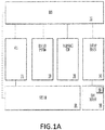
- FIGS. 1(a)-(d) illustrate an example of a system 100 level implementation of the aspects disclosed herein.
- system 100 interfaces with an electronic processing system in which various systems and display hardware are implemented with.
- FIG. 1(a) illustrates a system level diagram of the important components
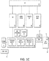
- FIGS. 1(b)-(c) illustrate the systems shown in FIG. 1(a) with a variety of signals communicated between the various componentry.
- a bus 150 is shown for illustrate purposes to indicate that the various systems/components of FIGS. 1(a)-(d) are electrically communicating with each other.
- a bus 150 allows signals to be propagated from the various connected peripheral devices, such as the electronic control unit (ECU) 110, a control system(s) 120, a telematics ECU 130, and the display driver 140.
- ECU electronice control unit
- the inclusion of the four connected peripheral devices described above is exemplary. Thus, other known electronic systems and architectures may be employed with the system 100 described within.
- the bus 150 is a wired or wireless (or combination of both) conduit that allows the information to be shared with the various elements shown in FIGS. 1(a)-(d) .
- the ECU 110 is processor that facilitates instructions being communicated from the various components. For example, control logic associated with the operation of the control system 120, the telematics ECU 130, and the display driver 140 may be contained in the ECU 110.
- control system 120 may represent various componentry/systems or sensors associated with the electronic system shown in FIGS. 1(a) and (b) .
- a vehicle which will be shown in further figures below.
- a sub-system control system 120 may exist for a variety of functions, such as safety, climate, doors/windows, entertainment, and the like.
- the control system(s) 120 interface with each of the sub-system. For example, if one of the sub-systems is associated with opening and closing a window, the ECU 110 may receive a signal of an up/down operation (from an interface device provided in the vehicle). Once the signal is received by the ECU 110, a command may be generated and propagated through the bus 150 to the control system 120 associated with the opening/closing of windows.
- the telematics ECU 130 is configured to receive/send data from other systems not shown in FIGS. 1(a)-(d) .
- the other systems may be a network connection, satellite connection, a local wireless connection (i.e. a BluetoothTM, or similar sort of local network connection), or the like.
- the ECU 110 may employ the telematics ECU 130 to communicate with and receive data from a third-party service, such as, streaming Internet channels, global positioning satellites, a cloud-network connection, and the like.
- the display driver 140 drives data to the dual display 160 (via display data 141). Digital information is received and is rendered via the dual display 160. Also shown in the dual display 160 is a dual display engager 161.
- the dual display engager 161 may activate (via a signal from system 100, via the bus 150 and other components), and either activate a dual display mode or a single display mode.
- FIG. 1(b) a system 100 for operating a dual display device 160 is explained in a sample operation of a variety of signals propagating to and from system 100 to the various components shown.
- the setup in FIG. 1(b) is similar to the setup shown in FIG. 1(a) ; however, various signals are shown that are used to communicate between the various elements and components.
- System 100 includes an information receiver 101, a display processor 102, and an instruction processor 103. Also shown is a storage device 105 which stores electronically a lookup table 106.
- the information receiver 101 is configured to receive information from the ECU 110 (either directly, or via the bus 150).
- the information may be one of the following, the current application 111 being presented on the dual display 160.
- a new application 112 may be requested to be presented on the dual display 160 as well.
- the new application 112 may run in a parallel fashion with the current application 111, or in another example, place the current application 111 in a background window, while placing the new application 112 in a foreground process.
- the source 131 of the new application 112 may also be received.
- the source 131 serves an indication of where the application was received from (or where it gets data from). For example, if the information associated with the new application 112 is sourced from a third-party source, such as a network or mobile device connected via the telematics ECU 130, this is indicated by source 131. This concept is further discussed in FIG. 1(c) .
- the display processor 102 determines one or both of 1) whether to engage the second display (or dis-engage the second display) of the dual display 160; and 2) provide direction as to which content is displayed on a first display and what content is displayed on a second display.
- the display processor 102 may incorporate various techniques to make this determination, such as employing a lookup table 106 (stored on storage device 105).
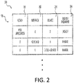
- a sample lookup table 106 is shown in FIG. 2 . Specifically, the decision as to whether to engage or dis-engage the dual display 160 (i.e. activate option 161) may be retrieved from the lookup table 106.
- a sample 200 of a lookup table 106 is depicted.
- the sample 200 is purely exemplary, and thus, an implementer of system 100 may customize the lookup table 106 based on a need or preference.
- the sample lookup table 200 includes the following fields: an action 201, an interface 202, a source 203, and whether to engage 204.
- the sample lookup table 200 may be used with the various examples and operations of system 100 explained below.
- field 204 discusses the concept of engaging a second display. By engaging the second display, this means that the second display is moved from a hidden or obscured view, to a visible view. This may be accomplished through various techniques. For example, a second display or a hidden display may be obscured by a primary (or first display). The second/hidden display may be in a slot and mechanically engaged to move to a visible location.
- the instruction processor 103 is configured to communicate the display orientation 142 to either the dual display 160 directly, or to other components (such as the ECU 110 and bus 150).
- the display orientation 142 is used to indicate whether the dual display 160 is in single display mode and/or dual display mode. Accordingly, the display data 141 may also use this information to determine which display to drive data to.
- FIG. 3 A first method 300 explaining the concepts of the operation of system 100 in FIG. 1 (b) is shown in FIG. 3 .
- an indication is received of a new application to be executed via a dual display assembly.
- a new application For example, in the vehicular context, a user may wish to turn on their infotainment system.
- the dual display assembly discussed herein is capable of showing one screen, or engaging a second screen along with the first screen.
- the decision to engage the second screen is based on signals associated with the various examples shown in FIGS. 1(b)-(d) .
- a user is not required to activate a function engaging, or not engaging the second screen.
- the method 300 proceeds to the determination in operation 330.
- operation 330 a determination is made as to whether the new application requires a second display. If yes, the method 300 proceeds to operation 340, in which a second display is presented to the viewer. If no, the method 300 proceeds to end 350, and no change is made to the display.
- the dual display is in a mode where at least two displays are being presented to the viewer.
- a determination is made as to whether the new application requires a second display. If yes, nothing changes, and the dual display remains with two displays being presented (see operation 335 with the line to end 350).
- the method 300 proceeds to operation 341.
- the second display is disengaged. I.e., if the second display is being presented to the viewer, the second display is automatically moved to a position of non-visibility to said viewer.
- FIGS. 6(a) and (b) illustrate an example of system 100, and specifically implementing a case employing the ideas discussed with method 300.
- a screen 161 is shown on a dual display assembly 160.
- the dual display assembly 160 includes a first screen 162 and a second screen 163 (which is not shown in FIG. 6(a) ).
- the second screen 163 is not shown because the second screen is in a disengaged orientation (i.e. not visible to a viewer/user).
- the second screen 163 is engaged.
- the dual display 160 is previously only showing a standard information screen 600 associated with standard information provided with the operation of a vehicle.
- screen 600 displays a fuel indicator and speed.
- a user selects an execution of an infotainment application (shown by screen 610).
- the second display 163 becomes engaged (i.e. visible to a user and in a non-hidden orientation).
- a mechanical motor may be configured to slide or make available the second display 163.
- the original screen 600 (showing vehicle operation information) is maintained on display 162, while the infotainment screen 163 is shown on the second display 163.
- a system such as those shown in FIG. 1(a)
- the aspects disclosed herein may be configured to present those new applications on a newly available (and previously hidden) display (i.e. second display 163).
- FIG. 1(c) illustrates another example implementation of system 100.
- a new application is initiated on the dual display 160.
- the new application is represented by new application data 112 (which is received via information receiver 101).
- the display processor 102 may receive the new application 112, as well as interface data 113 associated with the new application, and propagate a display orientation data 142 to the dual display 160.
- the dual display engager 161 may be initiated, and as such, a second display may protract (i.e. change from a hidden state to a shown state). The act of protracting may occur in an automatic function based on the interface being associated with the new application 112.
- the actual interface for example, a touch pad, a key board, a set of icons, or the like
- the decision as to whether to include an interface may be correlated and stored via lookup table 106.
- the interface associated with the new application may be presented on the secondary display.
- FIG. 4 A second method 400 explaining the concepts of the operation of system 100 in FIG. 1(c) is shown in FIG. 4 .
- the application information is received. For example, when a user engages or selects an application to execute or run through a system associated with the dual display, the information association with this application is received.
- the interface associated with this received application is retrieved. As shown in FIG. 2 , certain applications may be associated with specific interfaces. In operation 430, a determination is made as to whether a second display is required. The lookup table shown in FIG. 2 illustrates how specific interfaces and/or applications may be associated with a second display. If no, the method 400 proceeds to operation 450.
- the second display is automatically presented to a viewer and/or display (as explained in various example, the second display is normally hidden when not engaged or required).
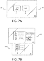
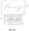
- FIGS. 7(a)-(c) illustrate examples of a variety of interfaces capable of being employed with the system 100 or method 400.
- the second display 163 is hidden (i.e. in a disengaged state).
- the second display 163 is showing a screen which shows two different applications available for selection, a music application 701 and a texting application 702.
- a second display becomes engaged (i.e. not hidden), and a screen 710 on the second display becomes available to the user.
- the interface of screen 710 matches an interface configured to operate a musical application 701.
- FIG. 7(c) the text application 702 is engaged. Similar to the above, an interface associated with screen 720 is presented on a screen that is engaged (i.e. not hidden) to the user/viewer via display 163. Specifically, in the case shown in FIG. 7(c) , a keyboard (touch screen keyboard) is presented via display 163.
- the aspects disclosed herein allow a specific interface to be presented on the second display of a dual display in response the specific interface matching an application on a primary interface.
- FIG. 1(d) illustrates another example implementation of system 100.
- source data 131 is communicated from the ECU 110 to the system 100 (via the information receiver 101).
- the source data 131 is also provided with the data 114.
- the source data 131 indicates where the data 114 was provided from.
- the telematics ECU 130 may receive information from a specific source, for example, a cloud-network provider.
- the display processor 102 may retrieve information (for example, lookup table 106), and identify that information from a specific source is to be shown/displayed via the second display of the dual display.
- the information processor 103 may communicate a display orientation data 142 signal to the dual display 160 (which has an engager 161, which is similar to the one explained above), and engage the second display of the dual display 160 based on a predetermined instruction to display information via the second display.
- FIG. 5 illustrates a method 500 explaining the concepts of the operation of system 100 in FIG. 1(d) .
- data is received from a source.
- data can be received from different areas with a system, or from a secondary source such as a network, via a telematics ECU 130.
- the second display may be engaged in a manner to partially extend outwards.
- the second display may be extended to a distance of 50% X, and thus, be shown at a partial extension.
- the systems shown within may be configured to reconfigure the display to be driven and rendered on the partial amount of the second display extended.
- the multiple display engager may be configured to move the second display to a visible state by extending the second display along a distance up to a maximum distance, and in response to extending an amount less than this maximum distance, the ECU may be configured to render information on the second display based on the amount of the display extended.
- the second display may show a full image re-sized for the partially engaged second display.
- a second display is engaged.
- a second display being engaged indicates that the display associated with the primary display (or first display) is now visible to a user/viewer.
- FIGS. 8(a)-(c) illustrate an example implementation of the system 100 described in FIG. 1(d) and method 500.
- a first display 162 of a dual display 160 is shown.
- the second display 163 is hidden (i.e. behind the first display 162 and configured to mechanically move without user instruction or engagement to a visible state).
- data 801 is received, and sourced from a cloud/network 802.
- the data 801 may be sourced from an ECU 110 and specifically from a telematics ECU 130.
- data sourced from a cloud/network 802 may be predetermined to engage the second display 163.
- the sample lookup table 106 stores a correspondence with data sourced from the cloud/network 802 as being associated with the engagement.
- the second display 163 is now engaged, with a screen 810 being sourced from data 801 received from the cloud/network 802.
- a dual display system 100 may be coupled with a dual display 160, capable of having two displays 162 and 163, with one of the screens hidden.
- the determination to engage, and the subsequent action to engage the second display 163 may occur independent of any action from a user or viewer of the dual display 160.
- the computing system includes a processor (CPU) and a system bus that couples various system components including a system memory such as read only memory (ROM) and random access memory (RAM), to the processor. Other system memory may be available for use as well.
- the computing system may include more than one processor or a group or cluster of computing system networked together to provide greater processing capability.
- the system bus may be any of several types of bus structures including a memory bus or memory controller, a peripheral bus, and a local bus using any of a variety of bus architectures.
- a basic input/output (BIOS) stored in the ROM or the like may provide basic routines that help to transfer information between elements within the computing system, such as during start-up.
- BIOS basic input/output
- the computing system further includes data stores, which maintain a database according to known database management systems.
- the data stores may be embodied in many forms, such as a hard disk drive, a magnetic disk drive, an optical disk drive, tape drive, or another type of computer readable media which can store data that are accessible by the processor, such as magnetic cassettes, flash memory cards, digital versatile disks, cartridges, random access memories (RAMs) and, read only memory (ROM).
- the data stores may be connected to the system bus by a drive interface.
- the data stores provide nonvolatile storage of computer readable instructions, data structures, program modules and other data for the computing system.
- the computing system may include an input device, such as a microphone for speech and audio, a touch sensitive screen for gesture or graphical input, keyboard, mouse, motion input, and so forth.
- An output device can include one or more of a number of output mechanisms.
- multimodal systems enable a user to provide multiple types of input to communicate with the computing system.
- a communications interface generally enables the computing device system to communicate with one or more other computing devices using various communication and network protocols.
- FIGS. 3-5 are for illustration purposes only and the described or similar steps may be performed at any appropriate time, including concurrently, individually, or in combination.
- many of the steps in these flow charts may take place simultaneously and/or in different orders than as shown and described.
- the disclosed systems may use processes and methods with additional, fewer, and/or different steps.
- Embodiments disclosed herein can be implemented in digital electronic circuitry, or in computer software, firmware, or hardware, including the herein disclosed structures and their equivalents. Some embodiments can be implemented as one or more computer programs, i.e., one or more modules of computer program instructions, encoded on a tangible computer storage medium for execution by one or more processors.
- a computer storage medium can be, or can be included in, a computer-readable storage device, a computer-readable storage substrate, or a random or serial access memory.
- the computer storage medium can also be, or can be included in, one or more separate tangible components or media such as multiple CDs, disks, or other storage devices.
- the computer storage medium does not include a transitory signal.
- the term processor encompasses all kinds of apparatus, devices, and machines for processing data, including by way of example a programmable processor, a computer, a system on a chip, or multiple ones, or combinations, of the foregoing.
- the processor can include special purpose logic circuitry, e.g., an FPGA (field programmable gate array) or an ASIC (application-specific integrated circuit).
- the processor also can include, in addition to hardware, code that creates an execution environment for the computer program in question, e.g., code that constitutes processor firmware, a protocol stack, a database management system, an operating system, a cross-platform runtime environment, a virtual machine, or a combination of one or more of them.
- a computer program (also known as a program, module, engine, software, software application, script, or code) can be written in any form of programming language, including compiled or interpreted languages, declarative or procedural languages, and the program can be deployed in any form, including as a stand-alone program or as a module, component, subroutine, object, or other unit suitable for use in a computing environment.
- a computer program may, but need not, correspond to a file in a file system.
- a program can be stored in a portion of a file that holds other programs or data (e.g., one or more scripts stored in a markup language document), in a single file dedicated to the program in question, or in multiple coordinated files (e.g., files that store one or more modules, sub-programs, or portions of code).
- a computer program can be deployed to be executed on one computer or on multiple computers that are located at one site or distributed across multiple sites and interconnected by a communication network.
- GUI graphical user interface
- Such GUI's may include interactive features such as pop-up or pull-down menus or lists, selection tabs, scannable features, and other features that can receive human inputs.
- the computing system disclosed herein can include clients and servers.
- a client and server are generally remote from each other and typically interact through a communications network. The relationship of client and server arises by virtue of computer programs running on the respective computers and having a client-server relationship to each other.
- a server transmits data (e.g., an HTML page) to a client device (e.g., for purposes of displaying data to and receiving user input from a user interacting with the client device).
- client device e.g., for purposes of displaying data to and receiving user input from a user interacting with the client device.
- Data generated at the client device e.g., a result of the user interaction
Landscapes
- Engineering & Computer Science (AREA)
- Theoretical Computer Science (AREA)
- Chemical & Material Sciences (AREA)
- Combustion & Propulsion (AREA)
- Transportation (AREA)
- Mechanical Engineering (AREA)
- Human Computer Interaction (AREA)
- Physics & Mathematics (AREA)
- General Engineering & Computer Science (AREA)
- General Physics & Mathematics (AREA)
- Multimedia (AREA)
- Computer Graphics (AREA)
- Health & Medical Sciences (AREA)
- Computing Systems (AREA)
- General Health & Medical Sciences (AREA)
- Medical Informatics (AREA)
- Computer Networks & Wireless Communication (AREA)
- Signal Processing (AREA)
- User Interface Of Digital Computer (AREA)
- Controls And Circuits For Display Device (AREA)
Applications Claiming Priority (1)
| Application Number | Priority Date | Filing Date | Title |
|---|---|---|---|
| US15/057,650 US10146494B2 (en) | 2016-03-01 | 2016-03-01 | System and method for operating a multiple display assembly |
Publications (2)
| Publication Number | Publication Date |
|---|---|
| EP3214541A1 true EP3214541A1 (de) | 2017-09-06 |
| EP3214541B1 EP3214541B1 (de) | 2021-10-06 |
Family
ID=58360812
Family Applications (1)
| Application Number | Title | Priority Date | Filing Date |
|---|---|---|---|
| EP17158729.8A Active EP3214541B1 (de) | 2016-03-01 | 2017-03-01 | System und verfahren für den betrieb einer mehrfachanzeigebaugruppe |
Country Status (3)
| Country | Link |
|---|---|
| US (1) | US10146494B2 (de) |
| EP (1) | EP3214541B1 (de) |
| CN (1) | CN107145315B (de) |
Families Citing this family (3)
| Publication number | Priority date | Publication date | Assignee | Title |
|---|---|---|---|---|
| CN108202601B (zh) * | 2017-12-29 | 2020-11-17 | 上海友衷科技有限公司 | 一种车内多屏交互方法及交互系统 |
| FR3077898B1 (fr) * | 2018-02-09 | 2020-01-24 | Psa Automobiles Sa | Systeme et procede de filtrage des commandes d’un systeme multi-ecrans tactiles de vehicule |
| JP6778735B2 (ja) * | 2018-12-26 | 2020-11-04 | 本田技研工業株式会社 | 表示装置、表示方法、およびプログラム |
Citations (2)
| Publication number | Priority date | Publication date | Assignee | Title |
|---|---|---|---|---|
| FR2971878A1 (fr) * | 2011-02-22 | 2012-08-24 | Peugeot Citroen Automobiles Sa | Systeme d’affichage d’information d’un vehicule automobile |
| EP3040849A1 (de) * | 2015-01-02 | 2016-07-06 | Volkswagen AG | Fortbewegungsmittel, Anwenderschnittstelle und Verfahren zur übergreifenden Anzeige eines Anzeigeinhaltes auf zwei Anzeigeeinrichtungen |
Family Cites Families (31)
| Publication number | Priority date | Publication date | Assignee | Title |
|---|---|---|---|---|
| US5946055A (en) * | 1996-08-16 | 1999-08-31 | Rosen Product Development, Inc. | Display unit |
| US6125286A (en) * | 1997-06-05 | 2000-09-26 | Motorola, Inc. | Communication device having multiple displays and method of operating the same |
| US7370983B2 (en) * | 2000-03-02 | 2008-05-13 | Donnelly Corporation | Interior mirror assembly with display |
| US20130080143A1 (en) * | 2011-09-27 | 2013-03-28 | Paul E. Reeves | Unified desktop docking behavior with device as master |
| US6804170B1 (en) * | 2002-03-28 | 2004-10-12 | C. C. & L. Company Limited | Multiple-display device |
| US9182937B2 (en) * | 2010-10-01 | 2015-11-10 | Z124 | Desktop reveal by moving a logical display stack with gestures |
| EP1789277A1 (de) * | 2004-09-16 | 2007-05-30 | DaimlerChrysler AG | Anzeigevorrichtung und verfahren zur anzeige für ein fahrzeug |
| KR100706676B1 (ko) * | 2004-12-13 | 2007-04-11 | 엘지.필립스 엘시디 주식회사 | 접철식 액정 디스플레이 화면을 구비한 모바일 단말기 |
| US20060214871A1 (en) | 2005-03-23 | 2006-09-28 | Ryuichi Iwamura | Additional thin display device for supplementing a primary display |
| KR20070087744A (ko) * | 2005-09-30 | 2007-08-29 | 엘지전자 주식회사 | 복수의 액정을 갖는 이동단말기 |
| CN100474359C (zh) * | 2006-01-20 | 2009-04-01 | 株式会社电装 | 显示器件 |
| US20100039350A1 (en) * | 2008-08-15 | 2010-02-18 | Sony Ericsson Mobile Communications Ab | Methods, systems, and computer program products for operating handheld electronic devices including moveable displays and related devices |
| US20100060547A1 (en) * | 2008-09-11 | 2010-03-11 | Sony Ericsson Mobile Communications Ab | Display Device and Method for Displaying Images in a Variable Size Display Area |
| US8378932B2 (en) * | 2009-05-11 | 2013-02-19 | Empire Technology Development, Llc | Foldable portable display |
| CN201571085U (zh) * | 2009-08-25 | 2010-09-01 | 中兴通讯股份有限公司 | 移动终端 |
| DE112009005391T5 (de) * | 2009-11-19 | 2012-09-13 | Lear Corporation | Fahrzeug mit flexibler Anzeigeeinrichtung |
| US8599105B2 (en) * | 2010-07-02 | 2013-12-03 | Nokia Corporation | Method and apparatus for implementing a multiple display mode |
| CN108681424B (zh) * | 2010-10-01 | 2021-08-31 | Z124 | 用户界面上的拖移手势 |
| CN102650897A (zh) * | 2011-02-25 | 2012-08-29 | 名硕电脑(苏州)有限公司 | 具有双显示屏的电子装置 |
| US9285944B1 (en) | 2011-04-22 | 2016-03-15 | Angel A. Penilla | Methods and systems for defining custom vehicle user interface configurations and cloud services for managing applications for the user interface and learned setting functions |
| US20130234951A1 (en) * | 2012-03-09 | 2013-09-12 | Jihwan Kim | Portable device and method for controlling the same |
| CN103377017A (zh) * | 2012-04-17 | 2013-10-30 | 鸿富锦精密工业(武汉)有限公司 | 多显示器控制系统 |
| GB201218004D0 (en) * | 2012-10-08 | 2012-11-21 | Plastic Logic Ltd | Foldable electronic display |
| KR20140046329A (ko) * | 2012-10-10 | 2014-04-18 | 삼성전자주식회사 | 멀티 디스플레이 장치 및 그 디스플레이 제어 방법 |
| US9070209B2 (en) * | 2012-12-21 | 2015-06-30 | Volkswagen Ag | Moving control console |
| JP2014181991A (ja) * | 2013-03-19 | 2014-09-29 | Japan Display Inc | 車載用メーター |
| US9298338B2 (en) * | 2013-04-08 | 2016-03-29 | Apple Inc. | Multiple displays for displaying workspaces |
| US9272671B2 (en) * | 2013-06-28 | 2016-03-01 | Faurecia Interior Systems, Inc. | Display screen arrangement and method of assembly |
| US9535602B2 (en) | 2013-07-15 | 2017-01-03 | BNC Systems Ltd. | System and method for promoting connectivity between a mobile communication device and a vehicle touch screen |
| JP6073497B2 (ja) * | 2013-11-12 | 2017-02-01 | 三菱電機株式会社 | 表示制御装置、情報表示方法および情報表示システム |
| US9573469B2 (en) * | 2014-09-25 | 2017-02-21 | Visteon Global Technologies, Inc. | Mechanically reconfigurable instrument cluster |
-
2016
- 2016-03-01 US US15/057,650 patent/US10146494B2/en active Active
-
2017
- 2017-02-28 CN CN201710113822.4A patent/CN107145315B/zh active Active
- 2017-03-01 EP EP17158729.8A patent/EP3214541B1/de active Active
Patent Citations (2)
| Publication number | Priority date | Publication date | Assignee | Title |
|---|---|---|---|---|
| FR2971878A1 (fr) * | 2011-02-22 | 2012-08-24 | Peugeot Citroen Automobiles Sa | Systeme d’affichage d’information d’un vehicule automobile |
| EP3040849A1 (de) * | 2015-01-02 | 2016-07-06 | Volkswagen AG | Fortbewegungsmittel, Anwenderschnittstelle und Verfahren zur übergreifenden Anzeige eines Anzeigeinhaltes auf zwei Anzeigeeinrichtungen |
Non-Patent Citations (2)
| Title |
|---|
| VISTEON CORPORATION: "Dual OLED Display", 9 January 2016 (2016-01-09), pages 1, XP054977424, Retrieved from the Internet <URL:https://www.youtube.com/watch?v=w3dk69mKigs> [retrieved on 20170609] * |
| VISTEON: "Visteon's Latest Instrument Clusters and Displays Bring Consumer Electronics Features into Vehicle to Enhance Driving Experience", 5 January 2016 (2016-01-05), XP055380213, Retrieved from the Internet <URL:http://www.visteon.com/media/newsroom/2016/160105_story1.html> [retrieved on 20170609] * |
Also Published As
| Publication number | Publication date |
|---|---|
| US10146494B2 (en) | 2018-12-04 |
| US20170255441A1 (en) | 2017-09-07 |
| EP3214541B1 (de) | 2021-10-06 |
| CN107145315A (zh) | 2017-09-08 |
| CN107145315B (zh) | 2022-02-25 |
Similar Documents
| Publication | Publication Date | Title |
|---|---|---|
| US9535602B2 (en) | System and method for promoting connectivity between a mobile communication device and a vehicle touch screen | |
| JP6622705B2 (ja) | 車両におけるオーディオビジュアルコンテンツの提示及びこれとの相互作用 | |
| EP3092559B1 (de) | Darstellung und interaktion mit audiovisuellem inhalt in einem fahrzeug | |
| CN104281429B (zh) | 驱动多层透明显示器 | |
| KR102396738B1 (ko) | 윈도우의 전환 및 배치의 결합 | |
| CN104935986A (zh) | 用于控制多源和多显示器的系统和方法 | |
| US20140152600A1 (en) | Touch display device for vehicle and display method applied for the same | |
| US20180262605A1 (en) | Method of outputting screens from server and client devices in performing mirrorlink | |
| EP3214541B1 (de) | System und verfahren für den betrieb einer mehrfachanzeigebaugruppe | |
| CN106143154A (zh) | 车辆的群集信息输出装置及其控制方法 | |
| CN114816142A (zh) | 一种车载屏幕的控制方法、设备和智能汽车 | |
| CN110072148B (zh) | 一种基于主从模式的车载信息系统的实现方法 | |
| EP3214508A1 (de) | Synchronisierung einer fahrzeuguhr mit einer sekundären vorrichtung | |
| US20120117198A1 (en) | System and method to recast information communicated between a host system and a remote interface | |
| WO2021016819A1 (zh) | 一种车辆的交互方法、设备、系统及可读存储介质 | |
| CN109683755B (zh) | 用户界面显示方法及装置、电子设备及存储介质 | |
| FR3001677A1 (fr) | Systeme telematique et procede de communication associe. | |
| CN116027998A (zh) | 车辆交互功能的智能显示方法及系统、电子设备、介质 | |
| EP4587284A1 (de) | Verfahren und vorrichtung zum bereitstellen einer mensch-maschine-schnittstelle für einen bildschirm eines fahrzeugs | |
| US20180284880A1 (en) | Controlling a vehicle-based human-machine interface via a wearable device | |
| CN120848882B (zh) | 用于显示信息的方法、车载系统、介质和程序产品 | |
| FR3140311A1 (fr) | Procédé et dispositif d’affichage d’une pluralité d’applications pour véhicule | |
| EP2779701A1 (de) | Verfahren zur Umwandlung einer Anwendung eines mobilen Gerätes in einen ablenkungsfreien Modus | |
| CN116679896A (zh) | 车辆多屏控制方法、电子设备、存储介质及车辆 |
Legal Events
| Date | Code | Title | Description |
|---|---|---|---|
| PUAI | Public reference made under article 153(3) epc to a published international application that has entered the european phase |
Free format text: ORIGINAL CODE: 0009012 |
|
| STAA | Information on the status of an ep patent application or granted ep patent |
Free format text: STATUS: THE APPLICATION HAS BEEN PUBLISHED |
|
| AK | Designated contracting states |
Kind code of ref document: A1 Designated state(s): AL AT BE BG CH CY CZ DE DK EE ES FI FR GB GR HR HU IE IS IT LI LT LU LV MC MK MT NL NO PL PT RO RS SE SI SK SM TR |
|
| AX | Request for extension of the european patent |
Extension state: BA ME |
|
| STAA | Information on the status of an ep patent application or granted ep patent |
Free format text: STATUS: REQUEST FOR EXAMINATION WAS MADE |
|
| 17P | Request for examination filed |
Effective date: 20180306 |
|
| RBV | Designated contracting states (corrected) |
Designated state(s): AL AT BE BG CH CY CZ DE DK EE ES FI FR GB GR HR HU IE IS IT LI LT LU LV MC MK MT NL NO PL PT RO RS SE SI SK SM TR |
|
| GRAP | Despatch of communication of intention to grant a patent |
Free format text: ORIGINAL CODE: EPIDOSNIGR1 |
|
| STAA | Information on the status of an ep patent application or granted ep patent |
Free format text: STATUS: GRANT OF PATENT IS INTENDED |
|
| INTG | Intention to grant announced |
Effective date: 20210514 |
|
| GRAS | Grant fee paid |
Free format text: ORIGINAL CODE: EPIDOSNIGR3 |
|
| GRAA | (expected) grant |
Free format text: ORIGINAL CODE: 0009210 |
|
| STAA | Information on the status of an ep patent application or granted ep patent |
Free format text: STATUS: THE PATENT HAS BEEN GRANTED |
|
| AK | Designated contracting states |
Kind code of ref document: B1 Designated state(s): AL AT BE BG CH CY CZ DE DK EE ES FI FR GB GR HR HU IE IS IT LI LT LU LV MC MK MT NL NO PL PT RO RS SE SI SK SM TR |
|
| REG | Reference to a national code |
Ref country code: GB Ref legal event code: FG4D |
|
| REG | Reference to a national code |
Ref country code: CH Ref legal event code: EP Ref country code: AT Ref legal event code: REF Ref document number: 1436808 Country of ref document: AT Kind code of ref document: T Effective date: 20211015 |
|
| REG | Reference to a national code |
Ref country code: DE Ref legal event code: R096 Ref document number: 602017047034 Country of ref document: DE |
|
| REG | Reference to a national code |
Ref country code: IE Ref legal event code: FG4D |
|
| REG | Reference to a national code |
Ref country code: LT Ref legal event code: MG9D |
|
| REG | Reference to a national code |
Ref country code: NL Ref legal event code: MP Effective date: 20211006 |
|
| REG | Reference to a national code |
Ref country code: AT Ref legal event code: MK05 Ref document number: 1436808 Country of ref document: AT Kind code of ref document: T Effective date: 20211006 |
|
| PG25 | Lapsed in a contracting state [announced via postgrant information from national office to epo] |
Ref country code: RS Free format text: LAPSE BECAUSE OF FAILURE TO SUBMIT A TRANSLATION OF THE DESCRIPTION OR TO PAY THE FEE WITHIN THE PRESCRIBED TIME-LIMIT Effective date: 20211006 Ref country code: LT Free format text: LAPSE BECAUSE OF FAILURE TO SUBMIT A TRANSLATION OF THE DESCRIPTION OR TO PAY THE FEE WITHIN THE PRESCRIBED TIME-LIMIT Effective date: 20211006 Ref country code: FI Free format text: LAPSE BECAUSE OF FAILURE TO SUBMIT A TRANSLATION OF THE DESCRIPTION OR TO PAY THE FEE WITHIN THE PRESCRIBED TIME-LIMIT Effective date: 20211006 Ref country code: BG Free format text: LAPSE BECAUSE OF FAILURE TO SUBMIT A TRANSLATION OF THE DESCRIPTION OR TO PAY THE FEE WITHIN THE PRESCRIBED TIME-LIMIT Effective date: 20220106 Ref country code: AT Free format text: LAPSE BECAUSE OF FAILURE TO SUBMIT A TRANSLATION OF THE DESCRIPTION OR TO PAY THE FEE WITHIN THE PRESCRIBED TIME-LIMIT Effective date: 20211006 |
|
| PG25 | Lapsed in a contracting state [announced via postgrant information from national office to epo] |
Ref country code: IS Free format text: LAPSE BECAUSE OF FAILURE TO SUBMIT A TRANSLATION OF THE DESCRIPTION OR TO PAY THE FEE WITHIN THE PRESCRIBED TIME-LIMIT Effective date: 20220206 Ref country code: SE Free format text: LAPSE BECAUSE OF FAILURE TO SUBMIT A TRANSLATION OF THE DESCRIPTION OR TO PAY THE FEE WITHIN THE PRESCRIBED TIME-LIMIT Effective date: 20211006 Ref country code: PT Free format text: LAPSE BECAUSE OF FAILURE TO SUBMIT A TRANSLATION OF THE DESCRIPTION OR TO PAY THE FEE WITHIN THE PRESCRIBED TIME-LIMIT Effective date: 20220207 Ref country code: PL Free format text: LAPSE BECAUSE OF FAILURE TO SUBMIT A TRANSLATION OF THE DESCRIPTION OR TO PAY THE FEE WITHIN THE PRESCRIBED TIME-LIMIT Effective date: 20211006 Ref country code: NO Free format text: LAPSE BECAUSE OF FAILURE TO SUBMIT A TRANSLATION OF THE DESCRIPTION OR TO PAY THE FEE WITHIN THE PRESCRIBED TIME-LIMIT Effective date: 20220106 Ref country code: NL Free format text: LAPSE BECAUSE OF FAILURE TO SUBMIT A TRANSLATION OF THE DESCRIPTION OR TO PAY THE FEE WITHIN THE PRESCRIBED TIME-LIMIT Effective date: 20211006 Ref country code: LV Free format text: LAPSE BECAUSE OF FAILURE TO SUBMIT A TRANSLATION OF THE DESCRIPTION OR TO PAY THE FEE WITHIN THE PRESCRIBED TIME-LIMIT Effective date: 20211006 Ref country code: HR Free format text: LAPSE BECAUSE OF FAILURE TO SUBMIT A TRANSLATION OF THE DESCRIPTION OR TO PAY THE FEE WITHIN THE PRESCRIBED TIME-LIMIT Effective date: 20211006 Ref country code: GR Free format text: LAPSE BECAUSE OF FAILURE TO SUBMIT A TRANSLATION OF THE DESCRIPTION OR TO PAY THE FEE WITHIN THE PRESCRIBED TIME-LIMIT Effective date: 20220107 Ref country code: ES Free format text: LAPSE BECAUSE OF FAILURE TO SUBMIT A TRANSLATION OF THE DESCRIPTION OR TO PAY THE FEE WITHIN THE PRESCRIBED TIME-LIMIT Effective date: 20211006 |
|
| REG | Reference to a national code |
Ref country code: DE Ref legal event code: R097 Ref document number: 602017047034 Country of ref document: DE |
|
| PG25 | Lapsed in a contracting state [announced via postgrant information from national office to epo] |
Ref country code: SM Free format text: LAPSE BECAUSE OF FAILURE TO SUBMIT A TRANSLATION OF THE DESCRIPTION OR TO PAY THE FEE WITHIN THE PRESCRIBED TIME-LIMIT Effective date: 20211006 Ref country code: SK Free format text: LAPSE BECAUSE OF FAILURE TO SUBMIT A TRANSLATION OF THE DESCRIPTION OR TO PAY THE FEE WITHIN THE PRESCRIBED TIME-LIMIT Effective date: 20211006 Ref country code: RO Free format text: LAPSE BECAUSE OF FAILURE TO SUBMIT A TRANSLATION OF THE DESCRIPTION OR TO PAY THE FEE WITHIN THE PRESCRIBED TIME-LIMIT Effective date: 20211006 Ref country code: EE Free format text: LAPSE BECAUSE OF FAILURE TO SUBMIT A TRANSLATION OF THE DESCRIPTION OR TO PAY THE FEE WITHIN THE PRESCRIBED TIME-LIMIT Effective date: 20211006 Ref country code: DK Free format text: LAPSE BECAUSE OF FAILURE TO SUBMIT A TRANSLATION OF THE DESCRIPTION OR TO PAY THE FEE WITHIN THE PRESCRIBED TIME-LIMIT Effective date: 20211006 Ref country code: CZ Free format text: LAPSE BECAUSE OF FAILURE TO SUBMIT A TRANSLATION OF THE DESCRIPTION OR TO PAY THE FEE WITHIN THE PRESCRIBED TIME-LIMIT Effective date: 20211006 |
|
| PLBE | No opposition filed within time limit |
Free format text: ORIGINAL CODE: 0009261 |
|
| STAA | Information on the status of an ep patent application or granted ep patent |
Free format text: STATUS: NO OPPOSITION FILED WITHIN TIME LIMIT |
|
| 26N | No opposition filed |
Effective date: 20220707 |
|
| PG25 | Lapsed in a contracting state [announced via postgrant information from national office to epo] |
Ref country code: MC Free format text: LAPSE BECAUSE OF FAILURE TO SUBMIT A TRANSLATION OF THE DESCRIPTION OR TO PAY THE FEE WITHIN THE PRESCRIBED TIME-LIMIT Effective date: 20211006 Ref country code: AL Free format text: LAPSE BECAUSE OF FAILURE TO SUBMIT A TRANSLATION OF THE DESCRIPTION OR TO PAY THE FEE WITHIN THE PRESCRIBED TIME-LIMIT Effective date: 20211006 |
|
| REG | Reference to a national code |
Ref country code: CH Ref legal event code: PL |
|
| PG25 | Lapsed in a contracting state [announced via postgrant information from national office to epo] |
Ref country code: SI Free format text: LAPSE BECAUSE OF FAILURE TO SUBMIT A TRANSLATION OF THE DESCRIPTION OR TO PAY THE FEE WITHIN THE PRESCRIBED TIME-LIMIT Effective date: 20211006 |
|
| REG | Reference to a national code |
Ref country code: BE Ref legal event code: MM Effective date: 20220331 |
|
| PG25 | Lapsed in a contracting state [announced via postgrant information from national office to epo] |
Ref country code: LU Free format text: LAPSE BECAUSE OF NON-PAYMENT OF DUE FEES Effective date: 20220301 Ref country code: LI Free format text: LAPSE BECAUSE OF NON-PAYMENT OF DUE FEES Effective date: 20220331 Ref country code: IE Free format text: LAPSE BECAUSE OF NON-PAYMENT OF DUE FEES Effective date: 20220301 Ref country code: CH Free format text: LAPSE BECAUSE OF NON-PAYMENT OF DUE FEES Effective date: 20220331 |
|
| PG25 | Lapsed in a contracting state [announced via postgrant information from national office to epo] |
Ref country code: BE Free format text: LAPSE BECAUSE OF NON-PAYMENT OF DUE FEES Effective date: 20220331 |
|
| PG25 | Lapsed in a contracting state [announced via postgrant information from national office to epo] |
Ref country code: IT Free format text: LAPSE BECAUSE OF FAILURE TO SUBMIT A TRANSLATION OF THE DESCRIPTION OR TO PAY THE FEE WITHIN THE PRESCRIBED TIME-LIMIT Effective date: 20211006 |
|
| P01 | Opt-out of the competence of the unified patent court (upc) registered |
Effective date: 20230527 |
|
| PG25 | Lapsed in a contracting state [announced via postgrant information from national office to epo] |
Ref country code: HU Free format text: LAPSE BECAUSE OF FAILURE TO SUBMIT A TRANSLATION OF THE DESCRIPTION OR TO PAY THE FEE WITHIN THE PRESCRIBED TIME-LIMIT; INVALID AB INITIO Effective date: 20170301 |
|
| PG25 | Lapsed in a contracting state [announced via postgrant information from national office to epo] |
Ref country code: MK Free format text: LAPSE BECAUSE OF FAILURE TO SUBMIT A TRANSLATION OF THE DESCRIPTION OR TO PAY THE FEE WITHIN THE PRESCRIBED TIME-LIMIT Effective date: 20211006 Ref country code: CY Free format text: LAPSE BECAUSE OF FAILURE TO SUBMIT A TRANSLATION OF THE DESCRIPTION OR TO PAY THE FEE WITHIN THE PRESCRIBED TIME-LIMIT Effective date: 20211006 |
|
| PG25 | Lapsed in a contracting state [announced via postgrant information from national office to epo] |
Ref country code: MT Free format text: LAPSE BECAUSE OF FAILURE TO SUBMIT A TRANSLATION OF THE DESCRIPTION OR TO PAY THE FEE WITHIN THE PRESCRIBED TIME-LIMIT Effective date: 20211006 |
|
| PGFP | Annual fee paid to national office [announced via postgrant information from national office to epo] |
Ref country code: DE Payment date: 20250218 Year of fee payment: 9 |
|
| PG25 | Lapsed in a contracting state [announced via postgrant information from national office to epo] |
Ref country code: TR Free format text: LAPSE BECAUSE OF FAILURE TO SUBMIT A TRANSLATION OF THE DESCRIPTION OR TO PAY THE FEE WITHIN THE PRESCRIBED TIME-LIMIT Effective date: 20211006 |
|
| PGFP | Annual fee paid to national office [announced via postgrant information from national office to epo] |
Ref country code: GB Payment date: 20260219 Year of fee payment: 10 |
|
| PGFP | Annual fee paid to national office [announced via postgrant information from national office to epo] |
Ref country code: FR Payment date: 20260219 Year of fee payment: 10 |