EP3214603B1 - Bildverarbeitung - Google Patents
Bildverarbeitung Download PDFInfo
- Publication number
- EP3214603B1 EP3214603B1 EP17150444.2A EP17150444A EP3214603B1 EP 3214603 B1 EP3214603 B1 EP 3214603B1 EP 17150444 A EP17150444 A EP 17150444A EP 3214603 B1 EP3214603 B1 EP 3214603B1
- Authority
- EP
- European Patent Office
- Prior art keywords
- sub
- threshold
- image
- regions
- binarization
- Prior art date
- Legal status (The legal status is an assumption and is not a legal conclusion. Google has not performed a legal analysis and makes no representation as to the accuracy of the status listed.)
- Active
Links
Images


Classifications
-
- G—PHYSICS
- G06—COMPUTING OR CALCULATING; COUNTING
- G06T—IMAGE DATA PROCESSING OR GENERATION, IN GENERAL
- G06T7/00—Image analysis
- G06T7/10—Segmentation; Edge detection
- G06T7/136—Segmentation; Edge detection involving thresholding
-
- G—PHYSICS
- G06—COMPUTING OR CALCULATING; COUNTING
- G06T—IMAGE DATA PROCESSING OR GENERATION, IN GENERAL
- G06T7/00—Image analysis
- G06T7/10—Segmentation; Edge detection
- G06T7/11—Region-based segmentation
-
- G—PHYSICS
- G06—COMPUTING OR CALCULATING; COUNTING
- G06T—IMAGE DATA PROCESSING OR GENERATION, IN GENERAL
- G06T2207/00—Indexing scheme for image analysis or image enhancement
- G06T2207/10—Image acquisition modality
- G06T2207/10141—Special mode during image acquisition
- G06T2207/10152—Varying illumination
-
- G—PHYSICS
- G06—COMPUTING OR CALCULATING; COUNTING
- G06T—IMAGE DATA PROCESSING OR GENERATION, IN GENERAL
- G06T2207/00—Indexing scheme for image analysis or image enhancement
- G06T2207/20—Special algorithmic details
- G06T2207/20004—Adaptive image processing
- G06T2207/20012—Locally adaptive
-
- G—PHYSICS
- G06—COMPUTING OR CALCULATING; COUNTING
- G06T—IMAGE DATA PROCESSING OR GENERATION, IN GENERAL
- G06T2207/00—Indexing scheme for image analysis or image enhancement
- G06T2207/20—Special algorithmic details
- G06T2207/20021—Dividing image into blocks, subimages or windows
Definitions
- the present disclosure relates to image processing.
- a binarization method may be a commonly-used method for processing an image, and many high-level algorithms used for target detection or recognition may rely on binarization effects. Taking license plate recognition as an example, a binarization process may be carried out for images of license plates before the images are recognized.
- One of the binarization methods is an OTSU binarization method, wherein an original image may be divided into a foreground image and a background image by using a threshold, and a difference between the background and the foreground may be the largest when the threshold is optimal.
- a criterion for measuring the difference may be determined according to the actual situation. However, in an image process according to the OTSU method, the criterion for measuring a difference may be a maximal variance between-class.
- An image may have a better binarization effect when illuminated evenly, whereas it may have a poor binarization effect when illuminated unevenly, for example, when illuminated by a light source from sides.
- a method of processing an image according to claim 1 is provided.
- a device for processing image according to claim 4 is provided.
- local or global binarization information of an image may be combined for use so that the image may have a better robustness no matter the image is illuminated evenly or unevenly.
- a binarization threshold of the image may be comparatively accurately obtained even though the image is divided into fewer sub-regions so that both accuracy and efficiency may be taken into account.
- the present disclosure further provides a concept of fitting matrix corresponding to an image division mode. Time spent in on-line calculation may be reduced by calculating the fitting matrix in advance, thereby improving a threshold calculation speed.
- a method for processing an image may be proposed for binarization of sub-regions of the image.
- a variation of a threshold between two adjacent sub-regions may be very large, which may cause a larger error to exist in a joint position, thereby making image quality be deteriorated.
- an image may be divided into a larger number of sub-regions to ensure that a variation of a threshold between sub-regions may be smaller, but this may cause a problem that an image processing efficiency is reduced because a complexity of calculation is increased.
- FIG. 1 illustrates a method for processing an image according to an example of the present disclosure, wherein the method may include following blocks.
- an inputted image is divided into a plurality of sub-regions.
- an inputted image is divided into a plurality of sub-regions, wherein each sub-region may be denoted by src (i, j) (i and j are natural numbers).
- the division mode may be various and may be determined according to practical conditions and requirements. For example, an image may be divided evenly or may be divided unevenly, a number of rows and a number of columns of sub-regions obtained after the division may be different, and the size of the sub-region may be changed according to needs.
- the inputted image may be divided into 2*2, 3*3, 2*3 or 3*4 sub-regions.
- a evenly-division mode may be adopted, and a number of rows and a number of columns of sub-regions obtained after the division may be equal.
- a binarization threshold for each of the sub-regions is calculated.
- a binarization threshold is calculated for each sub-region obtained at block 101.
- a method for calculating the binarization threshold of each sub-region may not be limited, and the known OTSU or a mean value calculation method or the like may be adopted.
- the mean value calculation method for example, a mean value of gray values of pixel points of each sub-region may be taken as the binarization threshold corresponding to the sub-region.
- a threshold surface of the image is fitted out according to the binarization thresholds of the sub-regions, wherein the threshold surface includes binarization thresholds respectively corresponding to each pixel point in the image.
- this block may be achieved through various blocks as shown in FIG. 2 .
- an equation may be established for the threshold surface by taking the binarization threshold and a central coordinate of each of the sub-regions as variables.
- the central coordinate of each sub-region may be determined according to an image division mode, and the central coordinate of the i th sub-region may be denoted as ( x i , , y i ).
- FIG. 3A shows an image division mode adopted in this example; and
- FIG. 3B shows a central coordinate matrix obtained by calculation according to the division mode in FIG. 3A .
- FIG. 4B for the central coordinate matrix if the image division takes the 2*2 mode as shown in FIG. 4A .
- a relationship between the binarization threshold of the image and the coordinate position of a pixel point in the image may be denoted by a plane equation.
- a plane equation For example, if a two-dimensional coordinate of a pixel point in the image is denoted by P(x, y), the binarization threshold corresponding to the pixel point may be denoted by t.
- a', b', c' and d are coefficients of the plane equation.
- a coefficient of the equation may be fitted out by substituting binarization thresholds and central coordinates of at least three sub-regions as known values of the variables into the equation.
- the fitting matrix and the binarization threshold of each sub-region may need to be known.
- the fitting matrix may be only related to a sub-region division mode but unrelated to an inputted image and the binarization threshold of each sub-region. Since the size of the inputted image is determined, once the sub-region division mode of the image is determined, the central coordinate of each sub-region may be determined, then a matrix A may be determined, and finally the fitting matrix may be calculated out. Therefore, a plurality of sub-region division modes and corresponding fitting matrixes may be preset to facilitate calculation of an image threshold without solving a transformation matrix on line.
- a fitting matrix corresponding to each of them may be calculated and saved.
- a fitting matrix corresponding to the image may be determined once a sub-region division mode is selected.
- a relational expression between a coordinate of a pixel point in the image and a binarization threshold of the pixel point may be obtained based on the coefficient of the equation.
- the relational expression between a coordinate of a pixel point in the image and a binarization threshold of the pixel point may be determined.
- a binarization threshold corresponding to each pixel point in the image may be obtained by substituting a coordinate of the pixel point into the relational expression so that the threshold surface of the image may be determined.
- the binarization threshold of each sub-region may be obtained, a matrix multiplication may be performed on a fitting matrix and the binarization threshold of each sub-region, and then a fitting relational expression between binarization threshold of a whole image and a pixel point in the image may be obtained. In this way, a global threshold surface of the whole image may be determined. By this means, time consumed in on-line calculation may be reduced.
- a relationship between the binarization threshold of the image and the coordinate position of a pixel point in the image may be obtained by using other models.
- a three-dimensional coordinate point defined by the binarization threshold and the central coordinate of each sub-region may be regarded as a point on an ellipsoid surface or a point on a spherical surface, and a relationship between them both may be obtained by establishing an ellipsoid surface equation or a spherical surface equation and fitting out an equation coefficient.
- the relationship between the binarization threshold and the pixel point location may be better reflected by using a plane equation.
- the image may be binarized based on the threshold surface.
- a fitting coefficient x may be obtained by multiplying the fitting matrix A by the sub-region threshold T.
- a threshold plane TH (x, y) may be obtained according to the fitting coefficient, wherein the calculation method is seen in Formula 3.
- an original image may be transformed into a binarization image based on the threshold surface.
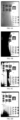
- FIG. 5A-FIG. 5D By using the method in the examples of the present disclosure, reference may be made to FIG. 5A-FIG. 5D for the whole threshold obtained.
- FIG. 5A is a sectional view of the original image
- FIG. 5B is a threshold sectional view obtained by using the OTSU method
- FIG. 5C is a threshold sectional view obtained by performing a local threshold calculation
- FIG. 5D is a threshold plane graph obtained according to the examples of the present disclosure.
- Gray part may indicate a background, and white part may indicate a foreground.
- the threshold obtained according to the OTSU method may be uniform with respect to the whole image. Effect difference between the OTSU method or the local binarization threshold calculation method and the method according to the examples of the present disclosure may be seen in FIG.
- FIG. 6A and FIG. 7A show original images;
- FIG. 6B and FIG. 7B respectively are effect views obtained by binarizing the original images using the OTSU method;
- FIG. 6C and FIG. 7C respectively are effect views obtained by dividing the original images into sub-regions and binarizing each sub-region;
- FIG. 6D and FIG. 7D respectively are effect views obtained by binarizing the original images according to the examples of the present disclosure.
- a large error may exist when an image which is unevenly illuminated is binarized using the OTSU method.
- the effect may be improved by using the local sub-region division method than the OTSU method.
- a larger error may exist in binarization segmentation since thresholds of joints among sub-regions are inconsistent.
- the background and the foreground may be well differentiated even though in case that illumination is uneven, and the error may be smaller than by using the existing methods.
- local or global binarization information of an image may be combined for use so that the image may have a better robustness no matter the image is illuminated evenly or unevenly.
- a binarization threshold of the image may be comparatively accurately obtained even though the image is divided into fewer sub-regions so that both accuracy and efficiency may be taken into account.
- a concept of fitting matrix corresponding to an image division mode may be proposed. Time spent in on-line calculation may be reduced by calculating the fitting matrix in advance, thereby improving a threshold calculation speed.
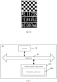
- FIG. 8 illustrates a device for processing an image according to the examples of the present disclosure.
- the device for processing an image 80 may include a processor 81, a machine-readable storage medium 82 and an internal bus 83.
- the processor 81 and the machine-readable storage medium 82 may intercommunicate via the internal bus 83.
- the above-described method for processing an image according to the examples of the present disclosure may be achieved by reading and executing, by the processor 81, machine-executable instructions in the machine-readable storage medium 82 corresponding to a binarization control logic 800.
- the machine-readable storage medium may be any electronic, magnetic, optical or other physical storage devices, which may contain or store information such as executable instructions or data, etc.
- the machine-readable storage medium may be a random access memory (RAM), a volatile memory, a nonvolatile memory, a flash memory, a memory drive (such as a hard disk drive), a solid state drive, any type of memory disks (such as an optical disk or a DVD and so on), or similar storage medium or a combination thereof.
- RAM random access memory
- a volatile memory such as a hard disk drive
- solid state drive any type of memory disks (such as an optical disk or a DVD and so on)
- any machine-readable storage medium as recited herein may be non-transient.
- the binarization control logic 800 is stored on the machine-readable storage medium 82.
- the control logic 800 functionally may include various functional modules as shown in FIG. 9 .
- a dividing module 801 may be configured to divide an image into a plurality of sub-regions.
- a threshold acquiring module 802 may calculate a binarization threshold for each of the sub-regions.
- a fitting module 803 may fit out a threshold surface of the image according to the binarization threshold of each of the sub-regions, wherein the threshold surface may include a binarization threshold corresponding to each pixel point in the image.
- a binarizing module 804 may binarize the image based on the threshold surface.
- the fitting module 803 may establish an equation for the threshold surface by taking the binarization threshold and a central coordinate of each of the sub-regions as variables.
- the fitting module 803 may fit out a coefficient of the equation by substituting binarization thresholds and central coordinates of at least three sub-regions as known values of the variables into the equation.
- the fitting module 803 may obtain a relational expression between a coordinate of a pixel point in the image and a binarization threshold of the pixel point based on the coefficient of the equation.
- the fitting module 803 may obtain a binarization threshold corresponding to each pixel point in the image by substituting a coordinate of the pixel point into the relational expression, and may determine the threshold surface of the image.
- the threshold acquiring module 802 may acquire the binarization threshold of each sub-region according to an OTSU method or a mean value calculation method.
Landscapes
- Engineering & Computer Science (AREA)
- Computer Vision & Pattern Recognition (AREA)
- Physics & Mathematics (AREA)
- General Physics & Mathematics (AREA)
- Theoretical Computer Science (AREA)
- Image Processing (AREA)
- Image Analysis (AREA)
- Facsimile Image Signal Circuits (AREA)
Claims (6)
- Computerimplementiertes Verfahren zum Umwandeln eines Bilds in ein binarisiertes Bild, umfassend:Unterteilen (101) eines Originalbilds in eine Vielzahl von Teilregionen gemäß einem vorbestimmten Teilungsmodus;Berechnen (102) eines Binarisierungsschwellenwerts für jede der Teilregionen;Anpassen (103) einer Schwellenwertfläche des Bilds gemäß dem Binarisierungsschwellenwert jeder der Teilregionen, die durch den vorbestimmten Teilungsmodus erlangt werden, wobei die Schwellenwertfläche einen Binarisierungsschwellenwert umfasst, der jedem Pixelpunkt in dem Bild entspricht; undUmwandeln (104) des Bilds in ein binarisiertes Bild basierend auf der Schwellenwertfläche,wobei ein Anpassen der Schwellenwertfläche des Bilds gemäß dem Binarisierungsschwellenwert jeder der Teilregionen, die durch den vorbestimmten Teilungsmodus erlangt werden, Folgendes umfasst:Erstellen einer Gleichung für die Schwellenwertfläche, indem der Binarisierungsschwellenwert und eine mittleren Koordinate jeder der Teilregionen als Variablen genommen werden;Anpassen eines Koeffizienten der Gleichung durch Einsetzen von Binarisierungsschwellenwerten und mittleren Koordinaten von mindestens drei Teilregionen als bekannte Werte der Variablen in die Gleichung;Erlangen eines relationalen Ausdrucks zwischen einer Koordinate eines Pixelpunkts in dem Bild und einem Binarisierungsschwellenwert des Pixelpunkts basierend auf dem Koeffizienten der Gleichung;Erlangen eines Binarisierungsschwellenwerts, der jedem Pixelpunkt in dem Bild entspricht, durch Einsetzen einer Koordinate des Pixelpunkts in den relationalen Ausdruck; undBestimmen der Schwellenwertfläche des Bilds gemäß den erlangten Binarisierungsschwellenwerten;wobei ein Anpassen des Koeffizienten der Gleichung durch Einsetzen von Binarisierungsschwellenwerten und mittleren Koordinaten von mindestens drei Teilregionen als bekannte Werte der Variablen in die Gleichung Folgendes umfasst;Bilden einer Schwellenwertmatrix T mit den Binarisierungsschwellenwerten der mindestens drei Teilregionen;Bilden einer mittleren Koordinatenmatrix A mit den mittleren Koordinaten von mindestens drei Teilregionen, wobei die mittlere Koordinatenmatrix A die mittleren Koordinaten der mindestens drei Teilregionen umfasst;Bestimmen einer Anpassungsmatrix B gemäß der mittleren Koordinatenmatrix A, wobei B = (ATA)-1AT ; undErlangen einer Koeffizientenmatrix x durch Multiplizieren der Anpassungsmatrix B mit der Schwellenwertmatrix T, wobei die Koeffizientenmatrix die zu lösenden Koeffizienten der Gleichung beinhaltet.
- Verfahren nach Anspruch 1, wobei ein Berechnen des Binarisierungsschwellenwerts für jede der Teilregionen Folgendes umfasst:
Erfassen des Binarisierungsschwellenwerts jeder Teilregion gemäß einem OTSU-Verfahren. - Verfahren nach Anspruch 1, wobei ein Berechnen des Binarisierungsschwellenwerts für jede der Teilregionen Folgendes umfasst:
Erfassen des Binarisierungsschwellenwerts jeder Teilregion gemäß einem Mittelwertberechnungsverfahren. - Vorrichtung (80) zum Umwandeln eines Bilds in ein binarisiertes Bild, umfassend:einen Prozessor (81); undnichtflüchtiges Speichermedium (82), auf dem maschinenausführbare Anweisungen für eine Binarisierungssteuerlogik gespeichert sind,wobei durch Ausführen der maschinenausführbaren Anweisungen der Prozessor zu Folgendem veranlasst wird:Unterteilen (101) eines Originalbilds in eine Vielzahl von Teilregionen gemäß einem vorbestimmten Teilungsmodus;Berechnen (102) eines Binarisierungsschwellenwerts für jede der Teilregionen;Anpassen (103) einer Schwellenwertfläche des Bilds gemäß dem Binarisierungsschwellenwert jeder der Teilregionen, die durch den vorbestimmten Teilungsmodus erlangt werden, wobei die Schwellenwertfläche einen Binarisierungsschwellenwert umfasst, der jeweils jedem Pixelpunkt in dem Bild entspricht; undUmwandeln (104) des Bilds in ein binarisiertes Bild basierend auf der Schwellenwertfläche, wobei ein Anpassen der Schwellenwertfläche des Bilds gemäß dem Binarisierungsschwellenwert jeder der Teilregionen, die durch den vorbestimmten Teilungsmodus erlangt werden, Folgendes umfasst:Erstellen einer Gleichung für die Schwellenwertfläche, indem der Binarisierungsschwellenwert und eine mittleren Koordinate jeder der Teilregionen als Variablen genommen werden;Anpassen eines Koeffizienten der Gleichung durch Einsetzen von Binarisierungsschwellenwerten und mittleren Koordinaten von mindestens drei Teilregionen als bekannte Werte der Variablen in die Gleichung;Erlangen eines relationalen Ausdrucks zwischen einer Koordinate eines Pixelpunkts in dem Bild und einem Binarisierungsschwellenwert des Pixelpunkts basierend auf dem Koeffizienten der Gleichung;Erlangen eines Binarisierungsschwellenwerts, der jedem Pixelpunkt in dem Bild entspricht, durch Einsetzen einer Koordinate des Pixelpunkts in den relationalen Ausdruck; undBestimmen der Schwellenwertfläche des Bilds gemäß den erlangten Binarisierungsschwellenwerten;wobei ein Anpassen des Koeffizienten der Gleichung durch Einsetzen von Binarisierungsschwellenwerten und mittleren Koordinaten von mindestens drei Teilregionen als bekannte Werte der Variablen in die Gleichung Folgendes umfasst;Bilden einer Schwellenwertmatrix T mit den Binarisierungsschwellenwerten der mindestens drei Teilregionen;Bilden einer mittleren Koordinatenmatrix A mit den mittleren Koordinaten von mindestens drei Teilregionen, wobei die mittlere Koordinatenmatrix A die mittleren Koordinaten der mindestens drei Teilregionen umfasst;Bestimmen einer Anpassungsmatrix B gemäß der mittleren Koordinatenmatrix A, wobei B = (ATA) - 1AT ; undErlangen einer Koeffizientenmatrix x durch Multiplizieren der Anpassungsmatrix B mit der Schwellenwertmatrix T, wobei die Koeffizientenmatrix die zu lösenden Koeffizienten der Gleichung beinhaltet.
- Vorrichtung nach Anspruch 4, wobei beim Berechnen des Binarisierungsschwellenwerts für jede der Teilregionen die maschinenausführbaren Anweisungen den Prozessor ferner zu Folgendem veranlassen:
Erfassen des Binarisierungsschwellenwerts jeder Teilregion gemäß einem OTSU-Verfahren. - Vorrichtung nach Anspruch 4, wobei beim Berechnen des Binarisierungsschwellenwerts für jede der Teilregionen die maschinenausführbaren Anweisungen den Prozessor ferner zu Folgendem veranlassen:
Erfassen des Binarisierungsschwellenwerts jeder Teilregion gemäß einem Mittelwertberechnungsverfahren.
Applications Claiming Priority (1)
| Application Number | Priority Date | Filing Date | Title |
|---|---|---|---|
| CN201610118800.2A CN105608708A (zh) | 2016-03-02 | 2016-03-02 | 基于分块平面拟合的图像二值化方法及装置 |
Publications (4)
| Publication Number | Publication Date |
|---|---|
| EP3214603A2 EP3214603A2 (de) | 2017-09-06 |
| EP3214603A3 EP3214603A3 (de) | 2017-09-13 |
| EP3214603C0 EP3214603C0 (de) | 2025-03-19 |
| EP3214603B1 true EP3214603B1 (de) | 2025-03-19 |
Family
ID=55988624
Family Applications (1)
| Application Number | Title | Priority Date | Filing Date |
|---|---|---|---|
| EP17150444.2A Active EP3214603B1 (de) | 2016-03-02 | 2017-01-05 | Bildverarbeitung |
Country Status (6)
| Country | Link |
|---|---|
| US (1) | US20170256061A1 (de) |
| EP (1) | EP3214603B1 (de) |
| CN (1) | CN105608708A (de) |
| ES (1) | ES3018783T3 (de) |
| HU (1) | HUE071403T2 (de) |
| PL (1) | PL3214603T3 (de) |
Families Citing this family (14)
| Publication number | Priority date | Publication date | Assignee | Title |
|---|---|---|---|---|
| CN106097255B (zh) * | 2016-05-26 | 2019-02-26 | 中国科学院光电技术研究所 | 用于点源哈特曼波前探测器的背景噪声特征估计方法 |
| CN106530279B (zh) * | 2016-10-15 | 2019-04-16 | 扬州奥泰光电生物技术有限公司 | 一种图像处理方法及系统 |
| CN106952281B (zh) * | 2017-05-15 | 2019-09-27 | 上海交通大学 | 一种焊缝轮廓特征识别及其焊道实时规划的方法 |
| US10540532B2 (en) * | 2017-09-29 | 2020-01-21 | Datalogic Ip Tech S.R.L. | System and method for detecting optical codes with damaged or incomplete finder patterns |
| CN108509819A (zh) * | 2018-03-07 | 2018-09-07 | 中山大学 | 一种用于光照不均匀的二维码二值化方法 |
| CN110110356A (zh) * | 2019-03-26 | 2019-08-09 | 江西理工大学 | 泰奥杨森机构足式运动机器人的制作方法及系统 |
| CN110426400B (zh) * | 2019-07-18 | 2021-03-05 | 成都新西旺自动化科技有限公司 | 针对触摸屏可操作区的自动打光方法 |
| CN110473194A (zh) * | 2019-08-12 | 2019-11-19 | 西南大学 | 基于多图像块阈值分割算法的水果表面缺陷检测方法 |
| CN110503605B (zh) * | 2019-08-27 | 2023-03-24 | Oppo广东移动通信有限公司 | 一种图像处理方法、装置及存储介质 |
| CN110533040A (zh) * | 2019-09-05 | 2019-12-03 | 哈尔滨理工大学 | 一种环形区域二值化图像处理方法及装置 |
| CN110853094B (zh) * | 2019-10-11 | 2020-12-29 | 北京文香信息技术有限公司 | 一种目标位置的阈值确定方法、装置、设备及存储介质 |
| CN110992387B (zh) * | 2019-11-08 | 2022-06-10 | 浪潮电子信息产业股份有限公司 | 一种图像处理方法、装置及电子设备和存储介质 |
| CN112750136B (zh) * | 2020-12-30 | 2023-12-05 | 深圳英集芯科技股份有限公司 | 一种图像处理方法和系统 |
| US12411041B2 (en) * | 2021-12-15 | 2025-09-09 | University Of Southern California | Off-axis laser detection |
Family Cites Families (2)
| Publication number | Priority date | Publication date | Assignee | Title |
|---|---|---|---|---|
| CN102663738A (zh) * | 2012-03-20 | 2012-09-12 | 苏州生物医学工程技术研究所 | 三维图像配准方法及系统 |
| CN104063874B (zh) * | 2014-07-09 | 2017-01-25 | 武汉科技大学 | 基于权值模型的灰度图像二值化算法定量评估方法 |
-
2016
- 2016-03-02 CN CN201610118800.2A patent/CN105608708A/zh active Pending
-
2017
- 2017-01-05 HU HUE17150444A patent/HUE071403T2/hu unknown
- 2017-01-05 EP EP17150444.2A patent/EP3214603B1/de active Active
- 2017-01-05 ES ES17150444T patent/ES3018783T3/es active Active
- 2017-01-05 PL PL17150444.2T patent/PL3214603T3/pl unknown
- 2017-01-17 US US15/408,229 patent/US20170256061A1/en not_active Abandoned
Also Published As
| Publication number | Publication date |
|---|---|
| ES3018783T3 (en) | 2025-05-19 |
| EP3214603C0 (de) | 2025-03-19 |
| US20170256061A1 (en) | 2017-09-07 |
| PL3214603T3 (pl) | 2025-07-14 |
| EP3214603A3 (de) | 2017-09-13 |
| HUE071403T2 (hu) | 2025-08-28 |
| CN105608708A (zh) | 2016-05-25 |
| EP3214603A2 (de) | 2017-09-06 |
Similar Documents
| Publication | Publication Date | Title |
|---|---|---|
| EP3214603B1 (de) | Bildverarbeitung | |
| EP3815043B1 (de) | Systeme und verfahren zur tiefenabschätzung durch affinitätsgelernte mit faltungsräumlichen ausbreitungsnetzwerken | |
| US10115035B2 (en) | Vision system and analytical method for planar surface segmentation | |
| US9536147B2 (en) | Optical flow tracking method and apparatus | |
| US8509536B2 (en) | Character recognition device and method and computer-readable medium controlling the same | |
| US9117281B2 (en) | Surface segmentation from RGB and depth images | |
| EP3637302B1 (de) | Bildsatzausrichtung | |
| US8538077B2 (en) | Detecting an interest point in an image using edges | |
| Fan et al. | Real-time stereo vision-based lane detection system | |
| US20120294516A1 (en) | Method for merging the regions in the image/video | |
| US11049275B2 (en) | Method of predicting depth values of lines, method of outputting three-dimensional (3D) lines, and apparatus thereof | |
| EP4006834B1 (de) | Erkennung von karosserieteilen durch einsatz von maschinellem lernen | |
| US9405959B2 (en) | System and method for classification of objects from 3D reconstruction | |
| EP3273412A1 (de) | Verfahren und vorrichtung für dreidimensionale modellierung | |
| JP5972498B2 (ja) | エッジ検出装置、エッジ検出方法およびプログラム | |
| CN114445499B (zh) | 棋盘格角点自动提取方法、系统、设备及介质 | |
| Wujanz et al. | Identification of stable areas in unreferenced laser scans for deformation measurement | |
| US20200151496A1 (en) | Devices, systems, and methods for anomaly detection | |
| US20180174328A1 (en) | Turning radius-based corner detection algorithm | |
| US20170316570A1 (en) | Image processing apparatus and method | |
| KR102398260B1 (ko) | 카메라 캘리브레이션 방법 및 장치 | |
| Li et al. | A method for accurate extraction of three-dimensional point cloud feature data in loading test of container ships | |
| CN115619678B (zh) | 一种图像变形的矫正方法、装置、计算机设备及存储介质 | |
| CN113538467B (zh) | 图像分割方法和装置及图像分割模型的训练方法和装置 | |
| CN113012132B (zh) | 一种图像相似度确定方法、装置及计算设备、存储介质 |
Legal Events
| Date | Code | Title | Description |
|---|---|---|---|
| PUAI | Public reference made under article 153(3) epc to a published international application that has entered the european phase |
Free format text: ORIGINAL CODE: 0009012 |
|
| STAA | Information on the status of an ep patent application or granted ep patent |
Free format text: STATUS: REQUEST FOR EXAMINATION WAS MADE |
|
| PUAL | Search report despatched |
Free format text: ORIGINAL CODE: 0009013 |
|
| 17P | Request for examination filed |
Effective date: 20170112 |
|
| AK | Designated contracting states |
Kind code of ref document: A2 Designated state(s): AL AT BE BG CH CY CZ DE DK EE ES FI FR GB GR HR HU IE IS IT LI LT LU LV MC MK MT NL NO PL PT RO RS SE SI SK SM TR |
|
| AX | Request for extension of the european patent |
Extension state: BA ME |
|
| AK | Designated contracting states |
Kind code of ref document: A3 Designated state(s): AL AT BE BG CH CY CZ DE DK EE ES FI FR GB GR HR HU IE IS IT LI LT LU LV MC MK MT NL NO PL PT RO RS SE SI SK SM TR |
|
| AX | Request for extension of the european patent |
Extension state: BA ME |
|
| RIC1 | Information provided on ipc code assigned before grant |
Ipc: G06T 7/12 20170101AFI20170810BHEP Ipc: G06T 7/11 20170101ALI20170810BHEP Ipc: G06T 7/194 20170101ALI20170810BHEP Ipc: G06T 7/136 20170101ALI20170810BHEP |
|
| RBV | Designated contracting states (corrected) |
Designated state(s): AL AT BE BG CH CY CZ DE DK EE ES FI FR GB GR HR HU IE IS IT LI LT LU LV MC MK MT NL NO PL PT RO RS SE SI SK SM TR |
|
| R17P | Request for examination filed (corrected) |
Effective date: 20170112 |
|
| STAA | Information on the status of an ep patent application or granted ep patent |
Free format text: STATUS: EXAMINATION IS IN PROGRESS |
|
| 17Q | First examination report despatched |
Effective date: 20210511 |
|
| GRAP | Despatch of communication of intention to grant a patent |
Free format text: ORIGINAL CODE: EPIDOSNIGR1 |
|
| STAA | Information on the status of an ep patent application or granted ep patent |
Free format text: STATUS: GRANT OF PATENT IS INTENDED |
|
| INTG | Intention to grant announced |
Effective date: 20241129 |
|
| GRAS | Grant fee paid |
Free format text: ORIGINAL CODE: EPIDOSNIGR3 |
|
| GRAA | (expected) grant |
Free format text: ORIGINAL CODE: 0009210 |
|
| STAA | Information on the status of an ep patent application or granted ep patent |
Free format text: STATUS: THE PATENT HAS BEEN GRANTED |
|
| AK | Designated contracting states |
Kind code of ref document: B1 Designated state(s): AL AT BE BG CH CY CZ DE DK EE ES FI FR GB GR HR HU IE IS IT LI LT LU LV MC MK MT NL NO PL PT RO RS SE SI SK SM TR |
|
| REG | Reference to a national code |
Ref country code: GB Ref legal event code: FG4D |
|
| REG | Reference to a national code |
Ref country code: CH Ref legal event code: EP |
|
| REG | Reference to a national code |
Ref country code: IE Ref legal event code: FG4D |
|
| REG | Reference to a national code |
Ref country code: DE Ref legal event code: R096 Ref document number: 602017088373 Country of ref document: DE |
|
| REG | Reference to a national code |
Ref country code: ES Ref legal event code: FG2A Ref document number: 3018783 Country of ref document: ES Kind code of ref document: T3 Effective date: 20250519 |
|
| U01 | Request for unitary effect filed |
Effective date: 20250415 |
|
| U07 | Unitary effect registered |
Designated state(s): AT BE BG DE DK EE FI FR IT LT LU LV MT NL PT RO SE SI Effective date: 20250422 |
|
| PG25 | Lapsed in a contracting state [announced via postgrant information from national office to epo] |
Ref country code: RS Free format text: LAPSE BECAUSE OF FAILURE TO SUBMIT A TRANSLATION OF THE DESCRIPTION OR TO PAY THE FEE WITHIN THE PRESCRIBED TIME-LIMIT Effective date: 20250619 |
|
| PG25 | Lapsed in a contracting state [announced via postgrant information from national office to epo] |
Ref country code: NO Free format text: LAPSE BECAUSE OF FAILURE TO SUBMIT A TRANSLATION OF THE DESCRIPTION OR TO PAY THE FEE WITHIN THE PRESCRIBED TIME-LIMIT Effective date: 20250619 |
|
| PG25 | Lapsed in a contracting state [announced via postgrant information from national office to epo] |
Ref country code: HR Free format text: LAPSE BECAUSE OF FAILURE TO SUBMIT A TRANSLATION OF THE DESCRIPTION OR TO PAY THE FEE WITHIN THE PRESCRIBED TIME-LIMIT Effective date: 20250319 |
|
| PG25 | Lapsed in a contracting state [announced via postgrant information from national office to epo] |
Ref country code: GR Free format text: LAPSE BECAUSE OF FAILURE TO SUBMIT A TRANSLATION OF THE DESCRIPTION OR TO PAY THE FEE WITHIN THE PRESCRIBED TIME-LIMIT Effective date: 20250620 |
|
| REG | Reference to a national code |
Ref country code: HU Ref legal event code: AG4A Ref document number: E071403 Country of ref document: HU |
|
| PG25 | Lapsed in a contracting state [announced via postgrant information from national office to epo] |
Ref country code: SM Free format text: LAPSE BECAUSE OF FAILURE TO SUBMIT A TRANSLATION OF THE DESCRIPTION OR TO PAY THE FEE WITHIN THE PRESCRIBED TIME-LIMIT Effective date: 20250319 |
|
| PG25 | Lapsed in a contracting state [announced via postgrant information from national office to epo] |
Ref country code: CZ Free format text: LAPSE BECAUSE OF FAILURE TO SUBMIT A TRANSLATION OF THE DESCRIPTION OR TO PAY THE FEE WITHIN THE PRESCRIBED TIME-LIMIT Effective date: 20250319 |
|
| PG25 | Lapsed in a contracting state [announced via postgrant information from national office to epo] |
Ref country code: SK Free format text: LAPSE BECAUSE OF FAILURE TO SUBMIT A TRANSLATION OF THE DESCRIPTION OR TO PAY THE FEE WITHIN THE PRESCRIBED TIME-LIMIT Effective date: 20250319 |
|
| PG25 | Lapsed in a contracting state [announced via postgrant information from national office to epo] |
Ref country code: IS Free format text: LAPSE BECAUSE OF FAILURE TO SUBMIT A TRANSLATION OF THE DESCRIPTION OR TO PAY THE FEE WITHIN THE PRESCRIBED TIME-LIMIT Effective date: 20250719 |
|
| PGFP | Annual fee paid to national office [announced via postgrant information from national office to epo] |
Ref country code: PL Payment date: 20251229 Year of fee payment: 10 |
|
| PLBE | No opposition filed within time limit |
Free format text: ORIGINAL CODE: 0009261 |
|
| STAA | Information on the status of an ep patent application or granted ep patent |
Free format text: STATUS: NO OPPOSITION FILED WITHIN TIME LIMIT |
|
| REG | Reference to a national code |
Ref country code: CH Ref legal event code: L10 Free format text: ST27 STATUS EVENT CODE: U-0-0-L10-L00 (AS PROVIDED BY THE NATIONAL OFFICE) Effective date: 20260128 |
|
| PGFP | Annual fee paid to national office [announced via postgrant information from national office to epo] |
Ref country code: HU Payment date: 20260123 Year of fee payment: 10 |
|
| 26N | No opposition filed |
Effective date: 20251222 |
|
| U20 | Renewal fee for the european patent with unitary effect paid |
Year of fee payment: 10 Effective date: 20260129 |