EP3214628A2 - Leitungsfrequenzdrehtransformator für computertomographiegerüst - Google Patents
Leitungsfrequenzdrehtransformator für computertomographiegerüst Download PDFInfo
- Publication number
- EP3214628A2 EP3214628A2 EP17000238.0A EP17000238A EP3214628A2 EP 3214628 A2 EP3214628 A2 EP 3214628A2 EP 17000238 A EP17000238 A EP 17000238A EP 3214628 A2 EP3214628 A2 EP 3214628A2
- Authority
- EP
- European Patent Office
- Prior art keywords
- line
- core
- primary
- gantry
- frequency
- Prior art date
- Legal status (The legal status is an assumption and is not a legal conclusion. Google has not performed a legal analysis and makes no representation as to the accuracy of the status listed.)
- Granted
Links
Images


Classifications
-
- H—ELECTRICITY
- H05—ELECTRIC TECHNIQUES NOT OTHERWISE PROVIDED FOR
- H05G—X-RAY TECHNIQUE
- H05G1/00—X-ray apparatus involving X-ray tubes; Circuits therefor
- H05G1/08—Electrical details
- H05G1/10—Power supply arrangements for feeding the X-ray tube
-
- H—ELECTRICITY
- H01—ELECTRIC ELEMENTS
- H01F—MAGNETS; INDUCTANCES; TRANSFORMERS; SELECTION OF MATERIALS FOR THEIR MAGNETIC PROPERTIES
- H01F38/00—Adaptations of transformers or inductances for specific applications or functions
- H01F38/18—Rotary transformers
-
- H—ELECTRICITY
- H01—ELECTRIC ELEMENTS
- H01F—MAGNETS; INDUCTANCES; TRANSFORMERS; SELECTION OF MATERIALS FOR THEIR MAGNETIC PROPERTIES
- H01F27/00—Details of transformers or inductances, in general
- H01F27/24—Magnetic cores
- H01F27/245—Magnetic cores made from sheets, e.g. grain-oriented
-
- H—ELECTRICITY
- H01—ELECTRIC ELEMENTS
- H01F—MAGNETS; INDUCTANCES; TRANSFORMERS; SELECTION OF MATERIALS FOR THEIR MAGNETIC PROPERTIES
- H01F27/00—Details of transformers or inductances, in general
- H01F27/28—Coils; Windings; Conductive connections
- H01F27/2823—Wires
- H01F27/2828—Construction of conductive connections, of leads
-
- H—ELECTRICITY
- H01—ELECTRIC ELEMENTS
- H01F—MAGNETS; INDUCTANCES; TRANSFORMERS; SELECTION OF MATERIALS FOR THEIR MAGNETIC PROPERTIES
- H01F3/00—Cores, Yokes, or armatures
- H01F3/02—Cores, Yokes, or armatures made from sheets
-
- H—ELECTRICITY
- H01—ELECTRIC ELEMENTS
- H01F—MAGNETS; INDUCTANCES; TRANSFORMERS; SELECTION OF MATERIALS FOR THEIR MAGNETIC PROPERTIES
- H01F3/00—Cores, Yokes, or armatures
- H01F3/10—Composite arrangements of magnetic circuits
- H01F3/14—Constrictions; Gaps, e.g. air-gaps
-
- H—ELECTRICITY
- H01—ELECTRIC ELEMENTS
- H01F—MAGNETS; INDUCTANCES; TRANSFORMERS; SELECTION OF MATERIALS FOR THEIR MAGNETIC PROPERTIES
- H01F38/00—Adaptations of transformers or inductances for specific applications or functions
- H01F38/14—Inductive couplings
-
- H—ELECTRICITY
- H05—ELECTRIC TECHNIQUES NOT OTHERWISE PROVIDED FOR
- H05G—X-RAY TECHNIQUE
- H05G1/00—X-ray apparatus involving X-ray tubes; Circuits therefor
- H05G1/08—Electrical details
Definitions
- the field of the disclosure relates generally to computed tomography (CT) systems and, more particularly, to a line-frequency rotary transformer for a CT gantry.
- CT computed tomography
- Approximating language may be applied to modify any quantitative representation that could permissibly vary without resulting in a change in the basic function to which it is related. Accordingly, a value modified by a term or terms, such as “about”, “approximately”, and “substantially”, are not to be limited to the precise value specified. In at least some instances, the approximating language may correspond to the precision of an instrument for measuring the value.
- range limitations may be combined and/or interchanged. Such ranges are identified and include all the sub-ranges contained therein unless context or language indicates otherwise.
- Low leakage inductance i.e., low leakage flux improves voltage regulation.
- Leakage flux degrades the proportional relationship of primary-to-secondary voltage in the transformer, particularly under heavy load.
- Leakage inductance is a function of the number of turns in the windings, which is directly related to the power rating and voltage regulation capability of the transformer. Fewer turns in the winding reduces leakage inductance and winding losses. Conversely, more turns in the winding increases leakage inductance and winding losses, and further degrades voltage regulation capability.
- Leakage inductance can be reduced by capacitance coupled in series with the windings.
- the losses due to increased magnetizing current can be mitigated by increasing the number of turns in the winding.
- the increased number of turns reduces the flux necessary to induce a given voltage in the winding.
- the increased number of turns in the windings increases winding losses and leakage inductance, and degrades the voltage regulation capability of the transformer.
- the losses from increased magnetizing current are further reduced with the addition of a shunt capacitor across the secondary windings.
- the shunt capacitor affects a division of the magnetizing current, permitting a reduction in number of turns in the winding. It is realized herein that series capacitances on the primary and secondary windings can mitigate the increased leakage inductance.
- a lower ratio of magnetizing inductance to leakage inductance is acceptable in a line-frequency rotary transformer for a gantry CT system than in conventional transformer design. Such a ratio may be 3:1 or lower in certain embodiments. It is further realized herein the resulting transformer losses and degraded voltage regulation are acceptable in a gantry CT system.
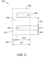
- Air gaps 206 separating side posts 202 and center post 204 have a gap width 212 of 1 unit.
- E-core 200 has a total length 214 of 4 units. Of total length 214, side posts 202 and center post 204 have post lengths 216 of 3 units, while a backplane 218 has a backplane length 220 of 1 unit.
- the precise dimensions of E-core 200 are scalable as each implementation requires and are largely dependent on power requirements. The ratios among the various dimensions are chosen at least partially to simplify manufacturing of E-core laminates.
- Each of primary core 302 and secondary core 304 include multiple E-core laminates arranged into rings.
- the primary ring is assembled as several arc-sections of E-core laminates. The arc-section construction simplifies assembly of each of primary core 302 and secondary core 304.
- the multiple E-core laminates of primary core 302 and secondary core 304 are interleaved with non-conductive spacers to reduce the weight of line-frequency rotary transformer 300.
- Line-frequency rotary transformer 300 includes a primary winding 308 and a secondary winding 310.
- Primary winding 308 includes primary terminals 312 and, likewise, secondary winding 310 includes secondary terminals 314.
- magnetic flux 318 is induced and flows through a magnetic circuit defined by primary core 302, air gap 306, and secondary core 304. Magnetic flux 318 induces a line-frequency output voltage 320 at secondary terminals 314.
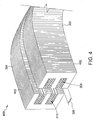
- FIG. 4 is a perspective diagram of an arc-section 400 of line-frequency rotary transformer 300 (shown in FIG. 3 ).
- Arc-section 400 includes primary core 302 and secondary core 304, each including multiple E-core laminates 402.
- E-core laminates 402 in certain embodiments, includes silicon steel E-core laminates interleaved with non-conductive spacers. In other embodiments, E-core laminates 402 include only E-core laminates manufactured from silicon steel or any other suitable material having a high relative magnetic permeability.
- primary core 302 and secondary core 304 are separated by air gap 306. Further, arc-section 400 includes primary winding 308 and secondary winding 310.
- FIG. 5 is a flow diagram of an exemplary embodiment of a method 500 of providing power to gantry CT system 100 using line-frequency rotary transformer 300 (shown in FIGs. 1 and 3 , respectively).
- Method 500 begins at a start step 510.
- a stator power step 520 line-frequency AC input power is provided to a primary side of line-frequency rotary transformer 300 at stator 104. More specifically, line-frequency input voltage 316 is applied to primary terminals 312 of primary winding 308, which induces magnetic flux 318 in primary core 302 and secondary core 304.
- FIG. 6 is a schematic diagram of gantry CT system 100 and line-frequency rotary transformer 300 (shown in FIGs. 1 and 3 , respectively).
- Gantry CT system 100 includes stator 104 and gantry 102 on opposite side of the schematic, coupled by line-frequency rotary transformer 300.
- Line-frequency AC power source 106 is illustrated an AC voltage source coupled across primary winding 308 of line-frequency rotary transformer 300.
- Line-frequency AC power source 106 delivers line-frequency AC input voltage 316 to primary winding 308.
- gantry 102 includes X-ray source 108 and X-ray detector 110 illustrated as loads.
- Line-frequency rotary transformer 300 supplies line-frequency AC output voltage 320 to X-ray source 108 and X-ray detector 110.
- Gantry 102 further includes a shunt capacitor 610 across secondary winding 310 of line-frequency rotary transformer 300.
- Gantry 102 and stator 104 further include series capacitors 620 and 630 coupled in series with primary winding 308 and secondary winding 310. Capacitors 620 and 630 mitigate the effects of leakage inductance in line-frequency rotary transformer 300.
- An exemplary technical effect of the methods, systems, and apparatus described herein includes at least one of: (a) improving gantry power quality by use of a non-contact slip ring for power transmission to the gantry; (b) reducing maintenance cost by use of the non-contact slip ring; (c) reducing necessary rectifiers, inverters, and transformers on the stator and gantry for converting to and from line-frequency AC power; (d) reducing weight on gantry by eliminating rectifiers, inverters, and transformers; and (e) reducing manufacturing costs of the gantry-stator slip ring.
- Exemplary embodiments of methods, systems, and apparatus for line-frequency rotary transformers are not limited to the specific embodiments described herein, but rather, components of systems and/or steps of the methods may be utilized independently and separately from other components and/or steps described herein.
- the methods may also be used in combination with other non-conventional line-frequency rotary transformers, and are not limited to practice with only the systems and methods as described herein.
- the exemplary embodiment can be implemented and utilized in connection with many other applications, equipment, and systems that may benefit from increased efficiency, reduced operational cost, and reduced capital expenditure.
Landscapes
- Engineering & Computer Science (AREA)
- Power Engineering (AREA)
- Chemical & Material Sciences (AREA)
- Composite Materials (AREA)
- Apparatus For Radiation Diagnosis (AREA)
- X-Ray Techniques (AREA)
Priority Applications (1)
| Application Number | Priority Date | Filing Date | Title |
|---|---|---|---|
| PL17000238T PL3214628T3 (pl) | 2016-02-15 | 2017-02-14 | Transformator obrotowy o częstotliwości sieciowej dla suwnicy ramowej tomografii komputerowej |
Applications Claiming Priority (1)
| Application Number | Priority Date | Filing Date | Title |
|---|---|---|---|
| US15/044,002 US10034361B2 (en) | 2016-02-15 | 2016-02-15 | Line-frequency rotary transformer for computed tomography gantry |
Publications (3)
| Publication Number | Publication Date |
|---|---|
| EP3214628A2 true EP3214628A2 (de) | 2017-09-06 |
| EP3214628A3 EP3214628A3 (de) | 2017-12-13 |
| EP3214628B1 EP3214628B1 (de) | 2020-04-29 |
Family
ID=58056950
Family Applications (1)
| Application Number | Title | Priority Date | Filing Date |
|---|---|---|---|
| EP17000238.0A Active EP3214628B1 (de) | 2016-02-15 | 2017-02-14 | Leitungsfrequenzdrehtransformator für computertomographiegerüst |
Country Status (5)
| Country | Link |
|---|---|
| US (1) | US10034361B2 (de) |
| EP (1) | EP3214628B1 (de) |
| CN (1) | CN107086117B (de) |
| CA (1) | CA2957460C (de) |
| PL (1) | PL3214628T3 (de) |
Families Citing this family (4)
| Publication number | Priority date | Publication date | Assignee | Title |
|---|---|---|---|---|
| CN107578907A (zh) * | 2017-10-19 | 2018-01-12 | 安徽大学 | 一种环形三相交流电感器 |
| US11751316B2 (en) * | 2019-11-05 | 2023-09-05 | Gulmay Limited | Power transfer and monitoring devices for X-ray tubes |
| CN116528446A (zh) * | 2022-10-28 | 2023-08-01 | 上海联影医疗科技股份有限公司 | 无线功率传输装置以及包含其的x射线成像设备 |
| CN116722413A (zh) * | 2023-07-28 | 2023-09-08 | 上海联影医疗科技股份有限公司 | 非接触式滑环系统以及医学扫描设备 |
Family Cites Families (25)
| Publication number | Priority date | Publication date | Assignee | Title |
|---|---|---|---|---|
| US1629311A (en) | 1925-03-12 | 1927-05-17 | Gen Electric | Magnetic core for electrical machinery |
| US4321572A (en) | 1980-11-13 | 1982-03-23 | The United States Of America As Represented By The Administrator Of The National Aeronautics And Space Administration | Non-contacting power transfer device |
| CN2034041U (zh) * | 1988-03-21 | 1989-03-15 | 刘春华 | 高速扫描的ct装置 |
| DE29503608U1 (de) | 1994-06-17 | 1995-09-14 | Schmall, Karl-Heinz, 76532 Baden-Baden | Elektromagnetischer Koppler |
| US5608771A (en) | 1995-10-23 | 1997-03-04 | General Electric Company | Contactless power transfer system for a rotational load |
| US6674836B2 (en) | 2000-01-17 | 2004-01-06 | Kabushiki Kaisha Toshiba | X-ray computer tomography apparatus |
| JP4569995B2 (ja) * | 2000-09-05 | 2010-10-27 | 株式会社日立メディコ | X線ct装置 |
| JP4833554B2 (ja) * | 2003-01-06 | 2011-12-07 | コーニンクレッカ フィリップス エレクトロニクス エヌ ヴィ | 放射線検出器モジュールと該放射線検出器モジュールを用いたコンピュータ断層撮影用スキャナ、および放射線検出方法 |
| US8350655B2 (en) | 2003-02-26 | 2013-01-08 | Analogic Corporation | Shielded power coupling device |
| AU2003293734A1 (en) | 2003-11-27 | 2005-07-21 | Schleifring Und Apparatebau Gmbh | Computer tomograph with contact-free energy transfer |
| US7197113B1 (en) | 2005-12-01 | 2007-03-27 | General Electric Company | Contactless power transfer system |
| JP5193530B2 (ja) | 2007-08-29 | 2013-05-08 | 株式会社東芝 | X線ct装置 |
| DE102008056359A1 (de) | 2007-11-07 | 2009-05-20 | Kabushiki Kaisha Toshiba | Röntgen-CT-Gerät und Verfahren zur Herstellung desselben |
| WO2009147552A1 (en) | 2008-06-02 | 2009-12-10 | Philips Intellectual Property & Standards Gmbh | Rotary power transformer and computer tomography gantry comprising same |
| CN102046088A (zh) | 2008-06-02 | 2011-05-04 | 皇家飞利浦电子股份有限公司 | 用于计算机断层成像机架的变压器 |
| CN102046091A (zh) | 2008-06-02 | 2011-05-04 | 皇家飞利浦电子股份有限公司 | 用于控制dc-ac转换器的x射线设备 |
| US20110075797A1 (en) | 2008-06-02 | 2011-03-31 | Koninklijke Philips Electronics N.V. | Device for a computer tomography gantry for transfering contactlessly electrical energy |
| WO2009147550A1 (en) * | 2008-06-02 | 2009-12-10 | Philips Intellectual Property & Standards Gmbh | Scalable power transfer device for providing electrical power for a computer tomography device |
| CN101732059A (zh) | 2008-11-21 | 2010-06-16 | Ge医疗系统环球技术有限公司 | 一种ct扫描设备 |
| RU2539328C2 (ru) | 2009-06-11 | 2015-01-20 | Конинклейке Филипс Электроникс Н.В. | Бесконтактная цепь питания |
| WO2011146065A1 (en) * | 2010-05-20 | 2011-11-24 | Schleifring Medical Systems Usa | A method and device for contact-less power and signal transmission for a high electrical power transformer |
| US9065382B2 (en) | 2011-12-16 | 2015-06-23 | Skyworks Solutions, Inc. | Circuits and methods for increasing output frequency of an LC oscillator |
| US9525376B2 (en) * | 2014-05-13 | 2016-12-20 | Gbox, Llc | Wound field synchronous machine with resonant field exciter |
| CN104037956B (zh) | 2014-06-27 | 2016-06-08 | 南京矽力杰半导体技术有限公司 | 谐振型非接触供电装置和电能接收端 |
| US10182777B2 (en) * | 2016-02-22 | 2019-01-22 | Morpho Detection, Llc | Open drum gantry for computed tomography system |
-
2016
- 2016-02-15 US US15/044,002 patent/US10034361B2/en active Active
-
2017
- 2017-02-09 CA CA2957460A patent/CA2957460C/en active Active
- 2017-02-14 PL PL17000238T patent/PL3214628T3/pl unknown
- 2017-02-14 EP EP17000238.0A patent/EP3214628B1/de active Active
- 2017-02-15 CN CN201710080918.5A patent/CN107086117B/zh active Active
Non-Patent Citations (1)
| Title |
|---|
| None |
Also Published As
| Publication number | Publication date |
|---|---|
| US20170238405A1 (en) | 2017-08-17 |
| CA2957460A1 (en) | 2017-08-15 |
| CN107086117B (zh) | 2021-06-04 |
| EP3214628B1 (de) | 2020-04-29 |
| CA2957460C (en) | 2024-03-12 |
| EP3214628A3 (de) | 2017-12-13 |
| PL3214628T3 (pl) | 2020-11-16 |
| US10034361B2 (en) | 2018-07-24 |
| CN107086117A (zh) | 2017-08-22 |
Similar Documents
| Publication | Publication Date | Title |
|---|---|---|
| CN103489564B (zh) | 功率转换器的磁性装置 | |
| CA2957460C (en) | Line-frequency rotary transformer for computed tomography gantry | |
| US9589718B2 (en) | Method for reducing or eliminating conducted common mode noise in a transformer | |
| CN1886810B (zh) | 采用无接触能量传输的计算机层析x射线摄影机 | |
| RU49646U1 (ru) | Трансформатор | |
| EP3208606B1 (de) | Gantry mit offener trommel für computertomographiesystem | |
| US20080074074A1 (en) | Integrated power conditioning system and housing for delivering operational power to a motor | |
| US10978241B2 (en) | Transformers having screen layers to reduce common mode noise | |
| EP2952912B1 (de) | Stromtransformatoreinheit und stromversorgungsvorrichtung mit elektromagnetischer induktion zur linearen ausgangsstromanpassung damit | |
| US11735357B2 (en) | Transformer with improved insulation structure | |
| US20160148747A1 (en) | Transformer | |
| JPWO2015016146A1 (ja) | ゲート電源装置及びこれを用いた半導体遮断器 | |
| JP2010136617A (ja) | 電気システム用の妨害電流補償方法および妨害電流補償装置 | |
| Zhu et al. | Surface spiral parallel and antiparallel winding designs for high efficiency, low spatial voltage stress, and inductive wireless power transfer systems | |
| Hagen et al. | Low-cost, printed circuit board construction, capacitively coupled excitation system for wound field synchronous machines | |
| Gao et al. | Design of A 50-kW medium frequency medium voltage transformer for 10-kV SiC-based dual active bridge converter | |
| US10923271B2 (en) | Core and transformer | |
| US10186370B1 (en) | Transformers with integrated inductors | |
| US20150279549A1 (en) | Systems and methods for promoting low loss in parallel conductors at high frequencies | |
| EP2234127B1 (de) | Hochspannungstransformator und Netzteil | |
| EP2285280A1 (de) | Vorrichtung für ein computertomographiegerüst zur kontaktlosen übertragung elektrischer energie | |
| KR102677672B1 (ko) | 변압기 임피던스 제어 장치 | |
| RU2486619C1 (ru) | Электрический трехфазный реактор с подмагничиванием | |
| RU2677681C1 (ru) | Управляемый электрический реактор | |
| US20250378986A1 (en) | Integrated planar transformer with horizontally-aligned air gaps and method |
Legal Events
| Date | Code | Title | Description |
|---|---|---|---|
| PUAI | Public reference made under article 153(3) epc to a published international application that has entered the european phase |
Free format text: ORIGINAL CODE: 0009012 |
|
| STAA | Information on the status of an ep patent application or granted ep patent |
Free format text: STATUS: THE APPLICATION HAS BEEN PUBLISHED |
|
| AK | Designated contracting states |
Kind code of ref document: A2 Designated state(s): AL AT BE BG CH CY CZ DE DK EE ES FI FR GB GR HR HU IE IS IT LI LT LU LV MC MK MT NL NO PL PT RO RS SE SI SK SM TR |
|
| AX | Request for extension of the european patent |
Extension state: BA ME |
|
| RIN1 | Information on inventor provided before grant (corrected) |
Inventor name: BASU, SAMIT KUMAR Inventor name: GARZON, PEDRO ANDRES Inventor name: MAGNUSON, ERIK E. |
|
| PUAL | Search report despatched |
Free format text: ORIGINAL CODE: 0009013 |
|
| AK | Designated contracting states |
Kind code of ref document: A3 Designated state(s): AL AT BE BG CH CY CZ DE DK EE ES FI FR GB GR HR HU IE IS IT LI LT LU LV MC MK MT NL NO PL PT RO RS SE SI SK SM TR |
|
| AX | Request for extension of the european patent |
Extension state: BA ME |
|
| RIC1 | Information provided on ipc code assigned before grant |
Ipc: H01F 27/245 20060101ALI20171107BHEP Ipc: H01F 38/14 20060101ALI20171107BHEP Ipc: H01F 38/18 20060101ALI20171107BHEP Ipc: H01F 3/02 20060101AFI20171107BHEP Ipc: H05G 1/10 20060101ALI20171107BHEP |
|
| STAA | Information on the status of an ep patent application or granted ep patent |
Free format text: STATUS: REQUEST FOR EXAMINATION WAS MADE |
|
| 17P | Request for examination filed |
Effective date: 20180607 |
|
| RBV | Designated contracting states (corrected) |
Designated state(s): AL AT BE BG CH CY CZ DE DK EE ES FI FR GB GR HR HU IE IS IT LI LT LU LV MC MK MT NL NO PL PT RO RS SE SI SK SM TR |
|
| STAA | Information on the status of an ep patent application or granted ep patent |
Free format text: STATUS: EXAMINATION IS IN PROGRESS |
|
| 17Q | First examination report despatched |
Effective date: 20190319 |
|
| GRAP | Despatch of communication of intention to grant a patent |
Free format text: ORIGINAL CODE: EPIDOSNIGR1 |
|
| STAA | Information on the status of an ep patent application or granted ep patent |
Free format text: STATUS: GRANT OF PATENT IS INTENDED |
|
| RAP1 | Party data changed (applicant data changed or rights of an application transferred) |
Owner name: MORPHO DETECTION, LLC. |
|
| INTG | Intention to grant announced |
Effective date: 20191125 |
|
| GRAS | Grant fee paid |
Free format text: ORIGINAL CODE: EPIDOSNIGR3 |
|
| GRAA | (expected) grant |
Free format text: ORIGINAL CODE: 0009210 |
|
| STAA | Information on the status of an ep patent application or granted ep patent |
Free format text: STATUS: THE PATENT HAS BEEN GRANTED |
|
| AK | Designated contracting states |
Kind code of ref document: B1 Designated state(s): AL AT BE BG CH CY CZ DE DK EE ES FI FR GB GR HR HU IE IS IT LI LT LU LV MC MK MT NL NO PL PT RO RS SE SI SK SM TR |
|
| REG | Reference to a national code |
Ref country code: GB Ref legal event code: FG4D |
|
| REG | Reference to a national code |
Ref country code: CH Ref legal event code: EP |
|
| REG | Reference to a national code |
Ref country code: AT Ref legal event code: REF Ref document number: 1264529 Country of ref document: AT Kind code of ref document: T Effective date: 20200515 |
|
| REG | Reference to a national code |
Ref country code: DE Ref legal event code: R096 Ref document number: 602017015442 Country of ref document: DE |
|
| REG | Reference to a national code |
Ref country code: IE Ref legal event code: FG4D |
|
| RAP2 | Party data changed (patent owner data changed or rights of a patent transferred) |
Owner name: SMITHS DETECTION INC. |
|
| REG | Reference to a national code |
Ref country code: DE Ref legal event code: R082 Ref document number: 602017015442 Country of ref document: DE Representative=s name: MUELLER-BORE & PARTNER PATENTANWAELTE PARTG MB, DE Ref country code: DE Ref legal event code: R081 Ref document number: 602017015442 Country of ref document: DE Owner name: SMITHS DETECTION INC., EDGEWOOD, US Free format text: FORMER OWNER: MORPHO DETECTION, LLC, NEWARK, CALIF., US |
|
| REG | Reference to a national code |
Ref country code: NL Ref legal event code: FP |
|
| REG | Reference to a national code |
Ref country code: NL Ref legal event code: PD Owner name: SMITHS DETECTION INC.; US Free format text: DETAILS ASSIGNMENT: CHANGE OF OWNER(S), ASSIGNMENT; FORMER OWNER NAME: MORPHO DETECTION, LLC. Effective date: 20200826 |
|
| REG | Reference to a national code |
Ref country code: LT Ref legal event code: MG4D |
|
| REG | Reference to a national code |
Ref country code: GB Ref legal event code: 732E Free format text: REGISTERED BETWEEN 20201001 AND 20201007 |
|
| PG25 | Lapsed in a contracting state [announced via postgrant information from national office to epo] |
Ref country code: NO Free format text: LAPSE BECAUSE OF FAILURE TO SUBMIT A TRANSLATION OF THE DESCRIPTION OR TO PAY THE FEE WITHIN THE PRESCRIBED TIME-LIMIT Effective date: 20200729 Ref country code: PT Free format text: LAPSE BECAUSE OF FAILURE TO SUBMIT A TRANSLATION OF THE DESCRIPTION OR TO PAY THE FEE WITHIN THE PRESCRIBED TIME-LIMIT Effective date: 20200831 Ref country code: SE Free format text: LAPSE BECAUSE OF FAILURE TO SUBMIT A TRANSLATION OF THE DESCRIPTION OR TO PAY THE FEE WITHIN THE PRESCRIBED TIME-LIMIT Effective date: 20200429 Ref country code: IS Free format text: LAPSE BECAUSE OF FAILURE TO SUBMIT A TRANSLATION OF THE DESCRIPTION OR TO PAY THE FEE WITHIN THE PRESCRIBED TIME-LIMIT Effective date: 20200829 Ref country code: FI Free format text: LAPSE BECAUSE OF FAILURE TO SUBMIT A TRANSLATION OF THE DESCRIPTION OR TO PAY THE FEE WITHIN THE PRESCRIBED TIME-LIMIT Effective date: 20200429 Ref country code: GR Free format text: LAPSE BECAUSE OF FAILURE TO SUBMIT A TRANSLATION OF THE DESCRIPTION OR TO PAY THE FEE WITHIN THE PRESCRIBED TIME-LIMIT Effective date: 20200730 Ref country code: LT Free format text: LAPSE BECAUSE OF FAILURE TO SUBMIT A TRANSLATION OF THE DESCRIPTION OR TO PAY THE FEE WITHIN THE PRESCRIBED TIME-LIMIT Effective date: 20200429 |
|
| REG | Reference to a national code |
Ref country code: AT Ref legal event code: MK05 Ref document number: 1264529 Country of ref document: AT Kind code of ref document: T Effective date: 20200429 |
|
| PG25 | Lapsed in a contracting state [announced via postgrant information from national office to epo] |
Ref country code: LV Free format text: LAPSE BECAUSE OF FAILURE TO SUBMIT A TRANSLATION OF THE DESCRIPTION OR TO PAY THE FEE WITHIN THE PRESCRIBED TIME-LIMIT Effective date: 20200429 Ref country code: HR Free format text: LAPSE BECAUSE OF FAILURE TO SUBMIT A TRANSLATION OF THE DESCRIPTION OR TO PAY THE FEE WITHIN THE PRESCRIBED TIME-LIMIT Effective date: 20200429 Ref country code: RS Free format text: LAPSE BECAUSE OF FAILURE TO SUBMIT A TRANSLATION OF THE DESCRIPTION OR TO PAY THE FEE WITHIN THE PRESCRIBED TIME-LIMIT Effective date: 20200429 Ref country code: BG Free format text: LAPSE BECAUSE OF FAILURE TO SUBMIT A TRANSLATION OF THE DESCRIPTION OR TO PAY THE FEE WITHIN THE PRESCRIBED TIME-LIMIT Effective date: 20200729 |
|
| PG25 | Lapsed in a contracting state [announced via postgrant information from national office to epo] |
Ref country code: AL Free format text: LAPSE BECAUSE OF FAILURE TO SUBMIT A TRANSLATION OF THE DESCRIPTION OR TO PAY THE FEE WITHIN THE PRESCRIBED TIME-LIMIT Effective date: 20200429 |
|
| PG25 | Lapsed in a contracting state [announced via postgrant information from national office to epo] |
Ref country code: AT Free format text: LAPSE BECAUSE OF FAILURE TO SUBMIT A TRANSLATION OF THE DESCRIPTION OR TO PAY THE FEE WITHIN THE PRESCRIBED TIME-LIMIT Effective date: 20200429 Ref country code: DK Free format text: LAPSE BECAUSE OF FAILURE TO SUBMIT A TRANSLATION OF THE DESCRIPTION OR TO PAY THE FEE WITHIN THE PRESCRIBED TIME-LIMIT Effective date: 20200429 Ref country code: ES Free format text: LAPSE BECAUSE OF FAILURE TO SUBMIT A TRANSLATION OF THE DESCRIPTION OR TO PAY THE FEE WITHIN THE PRESCRIBED TIME-LIMIT Effective date: 20200429 Ref country code: RO Free format text: LAPSE BECAUSE OF FAILURE TO SUBMIT A TRANSLATION OF THE DESCRIPTION OR TO PAY THE FEE WITHIN THE PRESCRIBED TIME-LIMIT Effective date: 20200429 Ref country code: CZ Free format text: LAPSE BECAUSE OF FAILURE TO SUBMIT A TRANSLATION OF THE DESCRIPTION OR TO PAY THE FEE WITHIN THE PRESCRIBED TIME-LIMIT Effective date: 20200429 Ref country code: SM Free format text: LAPSE BECAUSE OF FAILURE TO SUBMIT A TRANSLATION OF THE DESCRIPTION OR TO PAY THE FEE WITHIN THE PRESCRIBED TIME-LIMIT Effective date: 20200429 Ref country code: EE Free format text: LAPSE BECAUSE OF FAILURE TO SUBMIT A TRANSLATION OF THE DESCRIPTION OR TO PAY THE FEE WITHIN THE PRESCRIBED TIME-LIMIT Effective date: 20200429 Ref country code: IT Free format text: LAPSE BECAUSE OF FAILURE TO SUBMIT A TRANSLATION OF THE DESCRIPTION OR TO PAY THE FEE WITHIN THE PRESCRIBED TIME-LIMIT Effective date: 20200429 |
|
| REG | Reference to a national code |
Ref country code: DE Ref legal event code: R097 Ref document number: 602017015442 Country of ref document: DE |
|
| PG25 | Lapsed in a contracting state [announced via postgrant information from national office to epo] |
Ref country code: SK Free format text: LAPSE BECAUSE OF FAILURE TO SUBMIT A TRANSLATION OF THE DESCRIPTION OR TO PAY THE FEE WITHIN THE PRESCRIBED TIME-LIMIT Effective date: 20200429 |
|
| PLBE | No opposition filed within time limit |
Free format text: ORIGINAL CODE: 0009261 |
|
| STAA | Information on the status of an ep patent application or granted ep patent |
Free format text: STATUS: NO OPPOSITION FILED WITHIN TIME LIMIT |
|
| 26N | No opposition filed |
Effective date: 20210201 |
|
| PG25 | Lapsed in a contracting state [announced via postgrant information from national office to epo] |
Ref country code: SI Free format text: LAPSE BECAUSE OF FAILURE TO SUBMIT A TRANSLATION OF THE DESCRIPTION OR TO PAY THE FEE WITHIN THE PRESCRIBED TIME-LIMIT Effective date: 20200429 |
|
| PG25 | Lapsed in a contracting state [announced via postgrant information from national office to epo] |
Ref country code: MC Free format text: LAPSE BECAUSE OF FAILURE TO SUBMIT A TRANSLATION OF THE DESCRIPTION OR TO PAY THE FEE WITHIN THE PRESCRIBED TIME-LIMIT Effective date: 20200429 |
|
| REG | Reference to a national code |
Ref country code: BE Ref legal event code: MM Effective date: 20210228 |
|
| PG25 | Lapsed in a contracting state [announced via postgrant information from national office to epo] |
Ref country code: LI Free format text: LAPSE BECAUSE OF NON-PAYMENT OF DUE FEES Effective date: 20210228 Ref country code: LU Free format text: LAPSE BECAUSE OF NON-PAYMENT OF DUE FEES Effective date: 20210214 Ref country code: CH Free format text: LAPSE BECAUSE OF NON-PAYMENT OF DUE FEES Effective date: 20210228 |
|
| PG25 | Lapsed in a contracting state [announced via postgrant information from national office to epo] |
Ref country code: IE Free format text: LAPSE BECAUSE OF NON-PAYMENT OF DUE FEES Effective date: 20210214 |
|
| PG25 | Lapsed in a contracting state [announced via postgrant information from national office to epo] |
Ref country code: BE Free format text: LAPSE BECAUSE OF NON-PAYMENT OF DUE FEES Effective date: 20210228 |
|
| PG25 | Lapsed in a contracting state [announced via postgrant information from national office to epo] |
Ref country code: HU Free format text: LAPSE BECAUSE OF FAILURE TO SUBMIT A TRANSLATION OF THE DESCRIPTION OR TO PAY THE FEE WITHIN THE PRESCRIBED TIME-LIMIT; INVALID AB INITIO Effective date: 20170214 |
|
| PG25 | Lapsed in a contracting state [announced via postgrant information from national office to epo] |
Ref country code: CY Free format text: LAPSE BECAUSE OF FAILURE TO SUBMIT A TRANSLATION OF THE DESCRIPTION OR TO PAY THE FEE WITHIN THE PRESCRIBED TIME-LIMIT Effective date: 20200429 |
|
| P01 | Opt-out of the competence of the unified patent court (upc) registered |
Effective date: 20230528 |
|
| PG25 | Lapsed in a contracting state [announced via postgrant information from national office to epo] |
Ref country code: MK Free format text: LAPSE BECAUSE OF FAILURE TO SUBMIT A TRANSLATION OF THE DESCRIPTION OR TO PAY THE FEE WITHIN THE PRESCRIBED TIME-LIMIT Effective date: 20200429 |
|
| PG25 | Lapsed in a contracting state [announced via postgrant information from national office to epo] |
Ref country code: TR Free format text: LAPSE BECAUSE OF FAILURE TO SUBMIT A TRANSLATION OF THE DESCRIPTION OR TO PAY THE FEE WITHIN THE PRESCRIBED TIME-LIMIT Effective date: 20200429 |
|
| PG25 | Lapsed in a contracting state [announced via postgrant information from national office to epo] |
Ref country code: MT Free format text: LAPSE BECAUSE OF FAILURE TO SUBMIT A TRANSLATION OF THE DESCRIPTION OR TO PAY THE FEE WITHIN THE PRESCRIBED TIME-LIMIT Effective date: 20200429 |
|
| REG | Reference to a national code |
Ref country code: DE Ref legal event code: R081 Ref document number: 602017015442 Country of ref document: DE Owner name: SMITHS DETECTION GERMANY GMBH, DE Free format text: FORMER OWNER: SMITHS DETECTION INC., EDGEWOOD, MD., US Ref country code: DE Ref legal event code: R082 Ref document number: 602017015442 Country of ref document: DE Representative=s name: MATHYS & SQUIRE EUROPE PATENTANWAELTE PARTNERS, DE |
|
| REG | Reference to a national code |
Ref country code: GB Ref legal event code: 732E Free format text: REGISTERED BETWEEN 20251127 AND 20251203 |
|
| PGFP | Annual fee paid to national office [announced via postgrant information from national office to epo] |
Ref country code: FR Payment date: 20251208 Year of fee payment: 10 Ref country code: NL Payment date: 20251215 Year of fee payment: 10 |
|
| PGFP | Annual fee paid to national office [announced via postgrant information from national office to epo] |
Ref country code: PL Payment date: 20251212 Year of fee payment: 10 |
|
| PGFP | Annual fee paid to national office [announced via postgrant information from national office to epo] |
Ref country code: GB Payment date: 20260106 Year of fee payment: 10 |
|
| PGFP | Annual fee paid to national office [announced via postgrant information from national office to epo] |
Ref country code: DE Payment date: 20251224 Year of fee payment: 10 |