EP3214645A1 - Robot industriel - Google Patents
Robot industriel Download PDFInfo
- Publication number
- EP3214645A1 EP3214645A1 EP15855545.8A EP15855545A EP3214645A1 EP 3214645 A1 EP3214645 A1 EP 3214645A1 EP 15855545 A EP15855545 A EP 15855545A EP 3214645 A1 EP3214645 A1 EP 3214645A1
- Authority
- EP
- European Patent Office
- Prior art keywords
- arm part
- angle
- vertical direction
- outer diameter
- view
- Prior art date
- Legal status (The legal status is an assumption and is not a legal conclusion. Google has not performed a legal analysis and makes no representation as to the accuracy of the status listed.)
- Granted
Links
Images

Classifications
-
- H—ELECTRICITY
- H10—SEMICONDUCTOR DEVICES; ELECTRIC SOLID-STATE DEVICES NOT OTHERWISE PROVIDED FOR
- H10P—GENERIC PROCESSES OR APPARATUS FOR THE MANUFACTURE OR TREATMENT OF DEVICES COVERED BY CLASS H10
- H10P72/00—Handling or holding of wafers, substrates or devices during manufacture or treatment thereof
- H10P72/30—Handling or holding of wafers, substrates or devices during manufacture or treatment thereof for conveying, e.g. between different workstations
- H10P72/33—Handling or holding of wafers, substrates or devices during manufacture or treatment thereof for conveying, e.g. between different workstations into and out of processing chamber
- H10P72/3302—Mechanical parts of transfer devices
-
- B—PERFORMING OPERATIONS; TRANSPORTING
- B25—HAND TOOLS; PORTABLE POWER-DRIVEN TOOLS; MANIPULATORS
- B25J—MANIPULATORS; CHAMBERS PROVIDED WITH MANIPULATION DEVICES
- B25J9/00—Program-controlled manipulators
- B25J9/02—Program-controlled manipulators characterised by movement of the arms, e.g. cartesian coordinate type
- B25J9/04—Program-controlled manipulators characterised by movement of the arms, e.g. cartesian coordinate type by rotating at least one arm, excluding the head movement itself, e.g. cylindrical coordinate type or polar coordinate type
- B25J9/041—Cylindrical coordinate type
- B25J9/042—Cylindrical coordinate type comprising an articulated arm
- B25J9/043—Cylindrical coordinate type comprising an articulated arm double selective compliance articulated robot arms [SCARA]
-
- B—PERFORMING OPERATIONS; TRANSPORTING
- B25—HAND TOOLS; PORTABLE POWER-DRIVEN TOOLS; MANIPULATORS
- B25J—MANIPULATORS; CHAMBERS PROVIDED WITH MANIPULATION DEVICES
- B25J9/00—Program-controlled manipulators
- B25J9/06—Program-controlled manipulators characterised by multi-articulated arms
-
- H—ELECTRICITY
- H10—SEMICONDUCTOR DEVICES; ELECTRIC SOLID-STATE DEVICES NOT OTHERWISE PROVIDED FOR
- H10P—GENERIC PROCESSES OR APPARATUS FOR THE MANUFACTURE OR TREATMENT OF DEVICES COVERED BY CLASS H10
- H10P72/00—Handling or holding of wafers, substrates or devices during manufacture or treatment thereof
- H10P72/04—Apparatus for manufacture or treatment
- H10P72/0451—Apparatus for manufacturing or treating in a plurality of work-stations
- H10P72/0464—Apparatus for manufacturing or treating in a plurality of work-stations characterised by the construction of the transfer chamber
-
- H—ELECTRICITY
- H10—SEMICONDUCTOR DEVICES; ELECTRIC SOLID-STATE DEVICES NOT OTHERWISE PROVIDED FOR
- H10P—GENERIC PROCESSES OR APPARATUS FOR THE MANUFACTURE OR TREATMENT OF DEVICES COVERED BY CLASS H10
- H10P72/00—Handling or holding of wafers, substrates or devices during manufacture or treatment thereof
- H10P72/30—Handling or holding of wafers, substrates or devices during manufacture or treatment thereof for conveying, e.g. between different workstations
- H10P72/34—Handling or holding of wafers, substrates or devices during manufacture or treatment thereof for conveying, e.g. between different workstations the wafers being stored in a carrier, involving loading and unloading
- H10P72/3402—Mechanical parts of transfer devices
-
- H—ELECTRICITY
- H10—SEMICONDUCTOR DEVICES; ELECTRIC SOLID-STATE DEVICES NOT OTHERWISE PROVIDED FOR
- H10P—GENERIC PROCESSES OR APPARATUS FOR THE MANUFACTURE OR TREATMENT OF DEVICES COVERED BY CLASS H10
- H10P72/00—Handling or holding of wafers, substrates or devices during manufacture or treatment thereof
- H10P72/30—Handling or holding of wafers, substrates or devices during manufacture or treatment thereof for conveying, e.g. between different workstations
- H10P72/34—Handling or holding of wafers, substrates or devices during manufacture or treatment thereof for conveying, e.g. between different workstations the wafers being stored in a carrier, involving loading and unloading
- H10P72/3406—Handling or holding of wafers, substrates or devices during manufacture or treatment thereof for conveying, e.g. between different workstations the wafers being stored in a carrier, involving loading and unloading involving removal of lid, door or cover
-
- B—PERFORMING OPERATIONS; TRANSPORTING
- B25—HAND TOOLS; PORTABLE POWER-DRIVEN TOOLS; MANIPULATORS
- B25J—MANIPULATORS; CHAMBERS PROVIDED WITH MANIPULATION DEVICES
- B25J9/00—Program-controlled manipulators
- B25J9/02—Program-controlled manipulators characterised by movement of the arms, e.g. cartesian coordinate type
- B25J9/04—Program-controlled manipulators characterised by movement of the arms, e.g. cartesian coordinate type by rotating at least one arm, excluding the head movement itself, e.g. cylindrical coordinate type or polar coordinate type
- B25J9/041—Cylindrical coordinate type
- B25J9/042—Cylindrical coordinate type comprising an articulated arm
Definitions
- the present invention relates to an industrial robot for transferring a semiconductor wafer between a Front Open Unified Pod (FOUP) and a semiconductor wafer processing device, the industrial robot constituting a part of an Equipment Front End Module (EFEM).
- FOUP Front Open Unified Pod
- EFEM Equipment Front End Module
- An industrial robot described in Patent Document 1 includes a hand on which a semiconductor wafer is mounted, an arm to which the hand is connected at a top end side of the arm in such a way as to be rotatable, and a main body to which a root end side of the arm is connected in such a way as to be rotatable.
- the arm includes three arm parts; that is to say, a first arm part whose root end side is connected to the main body in such a way as to be rotatable, a second arm part whose root end side is connected to a top end side of the first arm part in such a way as to be rotatable, and a third arm part whose root end side is connected to a top end side of the second arm part in such a way as to be rotatable, wherein the hand is connected to a top end side of the third arm part in such a way as to be rotatable.
- Patent Document 1 Japanese Unexamined Patent Application Publication No. 2011-230256
- an industrial robot for transferring a semiconductor wafer between a Front Open Unified Pod (FOUP) and a semiconductor wafer processing device, the industrial robot constituting a part of an Equipment Front End Module (EFEM), and comprising: a hand on which the semiconductor wafer is mounted; an arm to which the hand is connected at a top end side of the arm in such a way as to be rotatable; and a main body to which a root end side of the arm is connected in such a way as to be rotatable; wherein, the arm includes a top-end-side arm part to which the hand is connected at a top end side in such a way as to be rotatable, and a second top-end-side arm part to which a root end side of the top-end-side arm part is connected at a top end side in such a way as to be rotatable; at least the top end side of the top-end-side arm part is a reducing
- each arm part length of the arm parts that constitute the arm is elongated and the rotation center of the arm in relation to the main body is made closer to the side of the FOUP or the side of the semiconductor wafer processing device, it becomes possible to avoid an interference between the top-end-side arm part and either the first wall surface or the second wall surface; and as a result of that, it becomes possible to appropriately transfer a semiconductor wafer.
- a first joint part as a connection part, connecting the top-end-side arm part and the hand is provided with a first bearing unit for supporting the hand in such a way as to make the hand rotatable in relation to the top-end-side arm part, and either a pulley or a gear for transmitting the power in order to turn the hand in relation to the arm top-end-side arm part; in the case where the first joint part is provided with the pulley, a center of the pulley and a center of the first bearing unit coincide with the first rotation center in a view from a vertical direction; in the case where the first joint part is provided with the gear, a center of the gear and the center of the first bearing unit coincide with the first rotation center in the view from the vertical direction; a second joint part as a connection part, connecting the second top-end-side arm part and the top-end-side arm part, is provided with a second bearing unit for supporting the top-end-side arm part in such a way as to make the top
- the arm is, for example, structured with three arm parts including the top-end-side arm part, the second top-end-side arm part, and a root-end-side arm part to which a root end side of the second top-end-side arm part is connected at a top end side in such a way as to be rotatable.
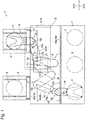
- FIG. 1 is a schematic plan view of a semiconductor manufacturing system 3 in which an industrial robot 1 according to an embodiment of the present invention is used.
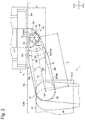
- FIG. 2 is a magnified view of a section "F" in FIG. 1 .
- An industrial robot 1 is a SCARA robot (Selective Compliance Assembly Robot Arm) for transferring a semiconductor wafer 2, wherein the industrial robot 1 is used while being built in the semiconductor manufacturing system 3.
- the industrial robot 1 and the semiconductor wafer 2 are represented as a 'robot 1' and a 'wafer 2', respectively.
- an X-direction in FIG. 1 that is perpendicular to a vertical direction is represented as a 'right-and-left direction', and meanwhile a Y-direction in FIG.
- a Y1-direction side and a Y2-direction side are represented as a front side and a rear side, respectively.
- the semiconductor manufacturing system 3 are provided with an EFEM 6 and a semiconductor wafer processing device 7 that executes a predetermined process for the wafer 2.
- the EFEM 6 is placed at a front side of the semiconductor wafer processing device 7.
- the robot 1 constitutes a part of the EFEM 6.
- the EFEM 6 is provided with a load port (not shown) for opening and closing a FOUP 8, and a chassis 10 for housing the robot 1.
- the chassis 10 is shaped so as to be a parallelepiped box being elongated in a right-and-left direction.
- a front wall 10a constituting a front side part of the chassis 10, and a rear wall 10b constituting a rear side part of the chassis 10 are each formed as a plate being perpendicular to a back-and-forth direction.
- An internal section of the chassis 10 is a clean space.
- the FOUP 8 Being manufactured in accordance with SEMI (Semiconductor Equipment and Materials Institute) standards, the FOUP 8 is able to store 25 or 13 wafers 2.
- the load port for opening and closing the FOUP 8 is placed at a front side of the chassis 10; and the semiconductor wafer processing device 7 and the FOUP 8 are placed in such a way as to face each other across the EFEM 6.
- the back-and-forth direction (the Y-direction) in the present embodiment is a first direction.
- a rear side surface 10c of the front wall 10a is a flat wall surface constituting one internal surface of the chassis 10 in a back-and-forth direction, the flat wall surface being at a side toward the FOUP 8, and being represented as a first wall surface.
- a front side surface 10d of the rear wall 10b is a flat wall surface constituting the other internal surface of the chassis 10 in the back-and-forth direction, the flat wall surface being in parallel with the rear side surface 10c as the first wall surface, and being at a side toward the semiconductor wafer processing device 7, and the front side surface 10d being represented as a second wall surface.
- the robot 1 includes; a hand 15 on which wafer 2 is mounted, an arm 16 to which the hand 15 is connected at a top end side in such a way as to be rotatable, and a main body 17 to which a root end side of the arm 16 is connected in such a way as to be rotatable.
- the arm 16 includes three arm parts 18 through 20; that is to say, the arm part 18 whose root end side is connected to the main body 17 in such a way as to be rotatable, the arm part 19 whose root end side is connected to a top end side of the arm part 18 in such a way as to be rotatable, and the arm part 20 whose root end side is connected to a top end side of the arm part 19 in such a way as to be rotatable.
- a root end side of the hand 15 is connected to a top end side of the arm part 20.
- the arm part 18 in the present embodiment is a root-end-side arm part
- the arm part 19 is a second top-end-side arm part
- the arm part 20 is a top-end-side arm part.
- the number of hands 15 to be connected to the top end side of the arm 16 may be one or two.
- the hand 15 is shaped so as to have an approximate Y-shape form in a view from a vertical direction, and the wafer 2 is mounted at a top end part of the hand 15 being Y-shaped.
- the arm parts 18 through 20 are formed so as to be hollow. Meanwhile, in the present embodiment, a length of the arm part 18, a length of the arm part 19, and a length of the arm part 19 are identical.
- the main body 17, the arm part 18, the arm part 19, the arm part 20, and the hand 15 are positioned in this order from a lower elevation in a vertical direction. Inside the main body 17, there is housed an arm elevating mechanism (not shown) for lifting up and down the hand 15 and the arm 16.
- a rotation center C1 of the arm part 18 with respect to the main body 17 (namely, a rotation center of the arm 16 with respect to the main body 17) is placed at a front side in relation to a center position of the chassis 10 in a back-and-forth direction.
- the robot 1 includes; an arm part drive mechanism for expanding/contracting a part of the arm 16, composed of the arm part 18 and the arm part 19, by way of turning the arm part 18 and the arm part 19 together; an arm drive mechanism for turning the arm part 20; and a hand drive mechanism for turning the hand 15.
- a joint part 23 as a connection part, connecting the hand 15 and the arm part 20, includes a bearing unit 24 for supporting the hand 15 in such a way as to make the hand 15 rotatable in relation to the arm part 20, and a pulley 25 for transmitting the power in order to turn the hand 15 in relation to the arm part 20 (refer to FIG. 2 ).
- the pulley 25 makes up a part of the hand drive mechanism.
- a rotation center of the hand 15 in relation to the arm part 20 in a view from a vertical direction is referred to as a rotation center C2
- the bearing unit 24 and the pulley 25 are coaxially placed in such a way that a center of the bearing unit 24 and a center of the pulley 25 coincide with the rotation center C2 in the view from the vertical direction.
- the joint part 23 in the present embodiment is a first joint part
- the bearing unit 24 is a first bearing unit.
- the rotation center C2 in the present embodiment is a first rotation center.
- a joint part 27 as a connecting section between the arm part 19 and the arm part 20 is provided with a bearing unit 28 for supporting the arm part 20 in such a way as to make the arm part 20 rotatable in relation to the arm part 19.
- a rotation center of the arm part 20 in relation to the arm part 19 in a view from a vertical direction is referred to as a rotation center C3
- the bearing unit 28 is placed in such a way that a center of the bearing unit 28 coincides with the rotation center C3 in the view from the vertical direction.
- an outer diameter of the bearing unit 28 is larger than an outer diameter of the bearing unit 24 and an outer diameter of the pulley 25.
- the joint part 27 in the present embodiment is a second joint part, and the bearing unit 28 is a second bearing unit.
- the rotation center C3 in the present embodiment is a second rotation center.
- the arm part drive mechanism collectively turns the arm part 18 and the arm part 19 in such a way that a trajectory of the rotation center C3 in the view from the vertical direction results in a line in parallel with a right-and-left direction.
- the arm part drive mechanism collectively turns the arm part 18 and the arm part 19 in such a way that the trajectory of the rotation center C3 in the view from the vertical direction results in a line in parallel with the right-and-left direction, wherein the line passes through the rotation center C1.
- the arm part 20 is configured with a reducing-width part 20a where a width gradually becomes narrower as a location closes toward a top end of the arm part 20 in a view from a vertical direction, and a constant-width part 20b where a width is constant in the same view.
- the arm part 20 is configured with the reducing-width part 20a where a width in a direction perpendicular to the arm part center line CL (namely, in a direction perpendicular to a direction from a root end of the arm part 20 toward a top end) gradually becomes narrower as a location closes toward the top end of the arm part 20 in the view from the vertical direction, and the constant-width part 20b where a width in the direction perpendicular to the arm part center line CL is constant in the same view.
- the arm part 20 is so formed as to be hollow; and inside the arm part 20, there are placed a motor for making up the hand drive mechanism, a belt for transmitting the power of the motor to the pulley 25, and a tension pulley for adjusting a tension of the belt, and the like.
- the reducing-width part 20a makes up a top end side part of the arm part 20, and meanwhile the constant-width part 20b makes up a root end side part of the arm part 20.
- the root end and the top end of the arm part 20 are each shaped so as to be almost arc-like in the view from the vertical direction.
- the arm part 20 is so shaped as to be line-symmetric with respect to the arm part center line CL as a symmetrical axis in the view from the vertical direction.
- an angle of the reducing-width part 20a (specifically, an angle between one side surface 20c and the other side surface 20d in the direction perpendicular to the arm part center line CL) in the view from the vertical direction is referred to as an angle ⁇ as shown in FIG. 2
- an angle between the arm part center line CL and the one side surface 20c is ⁇ /2 in the view from the vertical direction
- an angle between the arm part center line CL and the other side surface 20d is ⁇ /2 in the same view.
- a distance between one side surface 20e and the arm part center line CL in the direction perpendicular to the arm part center line CL is equal to a distance between the other side surface 20f and the arm part center line CL in the direction perpendicular to the arm part center line CL.
- a radius of curvature of the top end of the arm part 20 in the view from the vertical direction is referred to as a radius R;
- a length of the arm part center line CL in the view from the vertical direction is referred to as a length L; an angle of the arm part center line CL in relation to the rear side surface 10c in the view from the vertical direction, at a time just after the robot 1 has finished bringing the wafer 2 into the FOUP 8 (a situation as illustrated with a solid line in FIG.
- a first angle ⁇ 1 an angle of the arm part center line CL in relation to the front side surface 10d in the view from the vertical direction, at a time just after the robot 1 has finished bringing the wafer 2 into the semiconductor wafer processing device 7 (a situation as illustrated with a two-dot chain line in FIG.
- Relationships of formulas of "L ⁇ sin ⁇ 1 ⁇ d1 - R" and "L ⁇ sin ⁇ 2 ⁇ d2 - R" are established in the present embodiment.
- the first angle ⁇ 1 is smaller than the second angle ⁇ 2, and then a distance between the one side surface 20c (or the other side surface 20d) of the reducing-width part 20a of the arm part 20 and the rear side surface 10c, at the time just after the robot 1 has finished bringing the wafer 2 into the FOUP 8, is shorter than a distance between the one side surface 20c (or the other side surface 20d) and the front side surface 10d, at the time just after the robot 1 has finished bringing the wafer 2 into the semiconductor wafer processing device 7.
- the present embodiment it becomes possible to avoid an interference between the arm part 20 and either the rear side surface 10c or the front side surface 10d of the chassis 10, even in the case where each length of the arm part 18 through the arm part 20 is elongated and the rotation center C1 is made closer to a side of the FOUP 8. As a result of that, according to the present embodiment, it becomes possible to appropriately transfer the wafer 2.
- the arm 16 is structured with three arm parts, i.e., the arm part 18 through the arm part 20.
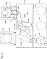
- the arm 16 may be configured with two arm parts, i.e., an arm part 19 and an arm part 20; wherein, the hand 15 is connected to a top end side of the arm part 20 in such a way as to be rotatable, and a root end side of the arm part 20 is connected to a top end side of the arm part 19 in such a way as to be rotatable, as shown in FIG. 3 .
- a root end side of the arm part 19 is connected to the main body 17 in such a way as to be rotatable.
- a rotation center C1 of the arm part 19 in relation to the main body 17 is placed at a rear side in relation to the center position of the chassis 10 in the back-and-forth direction.
- a configuration element being the same as in the embodiment described above is provided with the same reference numeral as in the above embodiment.
- the arm part 19 is a second top-end-side arm part
- the arm part 20 is a top-end-side arm part.
- an outer diameter of the bearing unit 24 is represented as an outer diameter D1
- an outer diameter of the pulley 25 is represented as an outer diameter D2
- the angle ⁇ is equal to or greater than an angle ⁇ 3 between two external common tangents TL that contact an outer periphery of the bearing unit 24 and an outer periphery of the bearing unit 28, in the view from the vertical direction.
- a relationship of a formula of " ⁇ ⁇ ⁇ 3" is established in this case.
- an entire section of the arm part 20 makes up, for example, a reducing-width part in which a width at a location gradually becomes narrower as the location closes toward the top end of the arm part 20, in such a way that the arm part 20 is not provided with the constant-width part 20b.
- the angle ⁇ is equal to or greater than an angle between two external common tangents that contact an outer periphery of the pulley 25 and the outer periphery of the bearing unit 28, in the view from the vertical direction.
- the joint part 23 is equipped with the pulley 25 that transmits the power for turning the hand 15 with respect to the arm part 20 in the embodiment described above, the joint part 23 may be equipped with a gear, such as a spur gear, instead of the pulley 25.
- an outer diameter of the gear is represented as an outer diameter D3; in the case where the relationship of the formula of " ⁇ ⁇ 2 ⁇ ⁇ 1" is established, and the outer diameter D1 is greater than the outer diameter D3, the angle ⁇ is equal to or greater than the ⁇ 3, in the view from the vertical direction.
- the angle ⁇ is equal to or greater than an angle between two external common tangents that contact an outer periphery of the gear and the outer periphery of the bearing unit 28, in the view from the vertical direction.
- the outer periphery of the bearing unit 28 is greater than the outer diameter of the gear.
- the second angle ⁇ 2 may be smaller than the first angle ⁇ 1; depending on a location of the robot 1 in the chassis 10, a configuration of the robot 1, a control method of the robot 1, and the like.
- the rotation center C1 is placed at a front side in relation to the center position of the chassis 10 in the back-and-forth direction, and the robot 1 is so placed as to be turned 90 degrees with respect to a vertical direction as a turning axis direction, from the status shown in FIG. 1
- the second angle ⁇ 2 is smaller than the first angle ⁇ 1.
- a relationship of a formula of " ⁇ ⁇ 2 ⁇ ⁇ 2" is established. Therefore, even in this case, the same effect as in the above embodiment can be obtained.
- the arm part drive mechanism collectively turns the arm part 18 and the arm part 19.
- the robot 1 may be equipped with a drive mechanism for turning the arm part 18 and a drive mechanism for turning the arm part 19 separately.
Landscapes
- Engineering & Computer Science (AREA)
- Robotics (AREA)
- Mechanical Engineering (AREA)
- Container, Conveyance, Adherence, Positioning, Of Wafer (AREA)
- Manipulator (AREA)
Applications Claiming Priority (2)
| Application Number | Priority Date | Filing Date | Title |
|---|---|---|---|
| JP2014221541A JP6374295B2 (ja) | 2014-10-30 | 2014-10-30 | 産業用ロボット |
| PCT/JP2015/079631 WO2016067983A1 (fr) | 2014-10-30 | 2015-10-21 | Robot industriel |
Publications (3)
| Publication Number | Publication Date |
|---|---|
| EP3214645A1 true EP3214645A1 (fr) | 2017-09-06 |
| EP3214645A4 EP3214645A4 (fr) | 2018-05-16 |
| EP3214645B1 EP3214645B1 (fr) | 2021-06-02 |
Family
ID=55857324
Family Applications (1)
| Application Number | Title | Priority Date | Filing Date |
|---|---|---|---|
| EP15855545.8A Active EP3214645B1 (fr) | 2014-10-30 | 2015-10-21 | Robot industriel |
Country Status (6)
| Country | Link |
|---|---|
| US (1) | US10052756B2 (fr) |
| EP (1) | EP3214645B1 (fr) |
| JP (1) | JP6374295B2 (fr) |
| KR (1) | KR102409169B1 (fr) |
| CN (1) | CN106463439B (fr) |
| WO (1) | WO2016067983A1 (fr) |
Families Citing this family (7)
| Publication number | Priority date | Publication date | Assignee | Title |
|---|---|---|---|---|
| WO2016172003A1 (fr) * | 2015-04-20 | 2016-10-27 | Applied Materials, Inc. | Mécanisme de chauffage de plaquette de chambre tampon et robot de support |
| US10580681B2 (en) | 2016-07-10 | 2020-03-03 | Yaskawa America Inc. | Robotic apparatus and method for transport of a workpiece |
| JP6774276B2 (ja) * | 2016-09-13 | 2020-10-21 | 川崎重工業株式会社 | 基板移載装置 |
| JP7169370B2 (ja) * | 2018-12-28 | 2022-11-10 | 川崎重工業株式会社 | ロボット制御装置、ロボットシステム及びロボット制御方法 |
| CN110154006A (zh) * | 2019-06-14 | 2019-08-23 | 苏州大学 | 基于遗传算法的scara机器人的臂长优化方法 |
| CN114286740B (zh) * | 2019-09-18 | 2024-02-27 | 株式会社富士 | 作业机器人以及作业系统 |
| JP7773024B2 (ja) * | 2021-07-29 | 2025-11-19 | シンフォニアテクノロジー株式会社 | 基板搬送装置 |
Family Cites Families (7)
| Publication number | Priority date | Publication date | Assignee | Title |
|---|---|---|---|---|
| US5789890A (en) * | 1996-03-22 | 1998-08-04 | Genmark Automation | Robot having multiple degrees of freedom |
| JP3339840B2 (ja) * | 1999-09-28 | 2002-10-28 | タツモ株式会社 | 水平多関節型産業用ロボット及びその制御方法 |
| JP3999712B2 (ja) * | 2003-07-14 | 2007-10-31 | 川崎重工業株式会社 | 多関節ロボット |
| JP4098338B2 (ja) * | 2006-07-20 | 2008-06-11 | 川崎重工業株式会社 | ウェハ移載装置および基板移載装置 |
| TWI398335B (zh) * | 2006-11-27 | 2013-06-11 | 日本電產三協股份有限公司 | Workpiece conveying system |
| JP5462064B2 (ja) | 2010-04-28 | 2014-04-02 | 日本電産サンキョー株式会社 | 産業用ロボット |
| JP5610952B2 (ja) * | 2010-09-24 | 2014-10-22 | 日本電産サンキョー株式会社 | 産業用ロボット |
-
2014
- 2014-10-30 JP JP2014221541A patent/JP6374295B2/ja active Active
-
2015
- 2015-10-21 WO PCT/JP2015/079631 patent/WO2016067983A1/fr not_active Ceased
- 2015-10-21 CN CN201580025293.1A patent/CN106463439B/zh active Active
- 2015-10-21 KR KR1020167034849A patent/KR102409169B1/ko active Active
- 2015-10-21 EP EP15855545.8A patent/EP3214645B1/fr active Active
- 2015-10-21 US US15/523,000 patent/US10052756B2/en active Active
Also Published As
| Publication number | Publication date |
|---|---|
| CN106463439A (zh) | 2017-02-22 |
| WO2016067983A1 (fr) | 2016-05-06 |
| US10052756B2 (en) | 2018-08-21 |
| US20170312915A1 (en) | 2017-11-02 |
| KR20170076619A (ko) | 2017-07-04 |
| CN106463439B (zh) | 2020-06-30 |
| KR102409169B1 (ko) | 2022-06-15 |
| JP2016092070A (ja) | 2016-05-23 |
| EP3214645A4 (fr) | 2018-05-16 |
| JP6374295B2 (ja) | 2018-08-15 |
| EP3214645B1 (fr) | 2021-06-02 |
Similar Documents
| Publication | Publication Date | Title |
|---|---|---|
| EP3214645B1 (fr) | Robot industriel | |
| US9446910B2 (en) | Substrate transfer robot, substrate transfer system, and method for transferring substrate | |
| US9281222B2 (en) | Wafer handling systems and methods | |
| US20190001500A1 (en) | Horizontal multi-joint robot and production method for horizontal multi-joint robot | |
| US11850742B2 (en) | Dual robot including splayed end effectors and systems and methods including same | |
| US8924118B2 (en) | Transfer system | |
| US8769771B2 (en) | Rotary shaft wire passage structure | |
| US20130202390A1 (en) | Industrial robot | |
| TW201343345A (zh) | 在電子裝置製造中經調適以輸送多個基材的完全地獨立的機器人系統、設備及方法 | |
| JP2015526896A (ja) | ブーム駆動装置、マルチアームロボット装置、電子デバイス処理システム、および電子デバイス製造システムにおいて基板を搬送するための方法 | |
| US10658216B2 (en) | Transfer system and transfer method | |
| US9252035B2 (en) | Substrate transfer system, substrate processing system, and substrate transfer robot | |
| US6988867B2 (en) | Transfer apparatus | |
| KR20020080534A (ko) | 웨이퍼 이송 장치 및 그 이송 방법 | |
| CN103817685A (zh) | 三平移并联机构及其支链 | |
| US20120087766A1 (en) | Transfer module | |
| US20130042714A1 (en) | Industrial robot | |
| TWI716888B (zh) | 機器人系統 | |
| CN107000204B (zh) | 工业用机器人 | |
| US20200061807A1 (en) | Industrial robot | |
| EP3406406A1 (fr) | Robot industriel |
Legal Events
| Date | Code | Title | Description |
|---|---|---|---|
| STAA | Information on the status of an ep patent application or granted ep patent |
Free format text: STATUS: THE INTERNATIONAL PUBLICATION HAS BEEN MADE |
|
| PUAI | Public reference made under article 153(3) epc to a published international application that has entered the european phase |
Free format text: ORIGINAL CODE: 0009012 |
|
| STAA | Information on the status of an ep patent application or granted ep patent |
Free format text: STATUS: REQUEST FOR EXAMINATION WAS MADE |
|
| 17P | Request for examination filed |
Effective date: 20170406 |
|
| AK | Designated contracting states |
Kind code of ref document: A1 Designated state(s): AL AT BE BG CH CY CZ DE DK EE ES FI FR GB GR HR HU IE IS IT LI LT LU LV MC MK MT NL NO PL PT RO RS SE SI SK SM TR |
|
| AX | Request for extension of the european patent |
Extension state: BA ME |
|
| DAV | Request for validation of the european patent (deleted) | ||
| DAX | Request for extension of the european patent (deleted) | ||
| A4 | Supplementary search report drawn up and despatched |
Effective date: 20180413 |
|
| RIC1 | Information provided on ipc code assigned before grant |
Ipc: B25J 9/06 20060101ALI20180409BHEP Ipc: B25J 9/04 20060101ALI20180409BHEP Ipc: H01L 21/677 20060101AFI20180409BHEP |
|
| GRAP | Despatch of communication of intention to grant a patent |
Free format text: ORIGINAL CODE: EPIDOSNIGR1 |
|
| STAA | Information on the status of an ep patent application or granted ep patent |
Free format text: STATUS: GRANT OF PATENT IS INTENDED |
|
| INTG | Intention to grant announced |
Effective date: 20210113 |
|
| GRAS | Grant fee paid |
Free format text: ORIGINAL CODE: EPIDOSNIGR3 |
|
| GRAA | (expected) grant |
Free format text: ORIGINAL CODE: 0009210 |
|
| STAA | Information on the status of an ep patent application or granted ep patent |
Free format text: STATUS: THE PATENT HAS BEEN GRANTED |
|
| REG | Reference to a national code |
Ref country code: CH Ref legal event code: EP |
|
| AK | Designated contracting states |
Kind code of ref document: B1 Designated state(s): AL AT BE BG CH CY CZ DE DK EE ES FI FR GB GR HR HU IE IS IT LI LT LU LV MC MK MT NL NO PL PT RO RS SE SI SK SM TR |
|
| REG | Reference to a national code |
Ref country code: GB Ref legal event code: FG4D |
|
| REG | Reference to a national code |
Ref country code: AT Ref legal event code: REF Ref document number: 1399234 Country of ref document: AT Kind code of ref document: T Effective date: 20210615 |
|
| REG | Reference to a national code |
Ref country code: IE Ref legal event code: FG4D |
|
| REG | Reference to a national code |
Ref country code: DE Ref legal event code: R096 Ref document number: 602015070089 Country of ref document: DE |
|
| REG | Reference to a national code |
Ref country code: LT Ref legal event code: MG9D |
|
| PG25 | Lapsed in a contracting state [announced via postgrant information from national office to epo] |
Ref country code: BG Free format text: LAPSE BECAUSE OF FAILURE TO SUBMIT A TRANSLATION OF THE DESCRIPTION OR TO PAY THE FEE WITHIN THE PRESCRIBED TIME-LIMIT Effective date: 20210902 Ref country code: HR Free format text: LAPSE BECAUSE OF FAILURE TO SUBMIT A TRANSLATION OF THE DESCRIPTION OR TO PAY THE FEE WITHIN THE PRESCRIBED TIME-LIMIT Effective date: 20210602 Ref country code: LT Free format text: LAPSE BECAUSE OF FAILURE TO SUBMIT A TRANSLATION OF THE DESCRIPTION OR TO PAY THE FEE WITHIN THE PRESCRIBED TIME-LIMIT Effective date: 20210602 Ref country code: FI Free format text: LAPSE BECAUSE OF FAILURE TO SUBMIT A TRANSLATION OF THE DESCRIPTION OR TO PAY THE FEE WITHIN THE PRESCRIBED TIME-LIMIT Effective date: 20210602 |
|
| REG | Reference to a national code |
Ref country code: NL Ref legal event code: MP Effective date: 20210602 |
|
| REG | Reference to a national code |
Ref country code: AT Ref legal event code: MK05 Ref document number: 1399234 Country of ref document: AT Kind code of ref document: T Effective date: 20210602 |
|
| PG25 | Lapsed in a contracting state [announced via postgrant information from national office to epo] |
Ref country code: GR Free format text: LAPSE BECAUSE OF FAILURE TO SUBMIT A TRANSLATION OF THE DESCRIPTION OR TO PAY THE FEE WITHIN THE PRESCRIBED TIME-LIMIT Effective date: 20210903 Ref country code: LV Free format text: LAPSE BECAUSE OF FAILURE TO SUBMIT A TRANSLATION OF THE DESCRIPTION OR TO PAY THE FEE WITHIN THE PRESCRIBED TIME-LIMIT Effective date: 20210602 Ref country code: NO Free format text: LAPSE BECAUSE OF FAILURE TO SUBMIT A TRANSLATION OF THE DESCRIPTION OR TO PAY THE FEE WITHIN THE PRESCRIBED TIME-LIMIT Effective date: 20210902 Ref country code: PL Free format text: LAPSE BECAUSE OF FAILURE TO SUBMIT A TRANSLATION OF THE DESCRIPTION OR TO PAY THE FEE WITHIN THE PRESCRIBED TIME-LIMIT Effective date: 20210602 Ref country code: RS Free format text: LAPSE BECAUSE OF FAILURE TO SUBMIT A TRANSLATION OF THE DESCRIPTION OR TO PAY THE FEE WITHIN THE PRESCRIBED TIME-LIMIT Effective date: 20210602 Ref country code: SE Free format text: LAPSE BECAUSE OF FAILURE TO SUBMIT A TRANSLATION OF THE DESCRIPTION OR TO PAY THE FEE WITHIN THE PRESCRIBED TIME-LIMIT Effective date: 20210602 |
|
| PG25 | Lapsed in a contracting state [announced via postgrant information from national office to epo] |
Ref country code: SK Free format text: LAPSE BECAUSE OF FAILURE TO SUBMIT A TRANSLATION OF THE DESCRIPTION OR TO PAY THE FEE WITHIN THE PRESCRIBED TIME-LIMIT Effective date: 20210602 Ref country code: SM Free format text: LAPSE BECAUSE OF FAILURE TO SUBMIT A TRANSLATION OF THE DESCRIPTION OR TO PAY THE FEE WITHIN THE PRESCRIBED TIME-LIMIT Effective date: 20210602 Ref country code: EE Free format text: LAPSE BECAUSE OF FAILURE TO SUBMIT A TRANSLATION OF THE DESCRIPTION OR TO PAY THE FEE WITHIN THE PRESCRIBED TIME-LIMIT Effective date: 20210602 Ref country code: CZ Free format text: LAPSE BECAUSE OF FAILURE TO SUBMIT A TRANSLATION OF THE DESCRIPTION OR TO PAY THE FEE WITHIN THE PRESCRIBED TIME-LIMIT Effective date: 20210602 Ref country code: RO Free format text: LAPSE BECAUSE OF FAILURE TO SUBMIT A TRANSLATION OF THE DESCRIPTION OR TO PAY THE FEE WITHIN THE PRESCRIBED TIME-LIMIT Effective date: 20210602 Ref country code: NL Free format text: LAPSE BECAUSE OF FAILURE TO SUBMIT A TRANSLATION OF THE DESCRIPTION OR TO PAY THE FEE WITHIN THE PRESCRIBED TIME-LIMIT Effective date: 20210602 Ref country code: PT Free format text: LAPSE BECAUSE OF FAILURE TO SUBMIT A TRANSLATION OF THE DESCRIPTION OR TO PAY THE FEE WITHIN THE PRESCRIBED TIME-LIMIT Effective date: 20211004 Ref country code: ES Free format text: LAPSE BECAUSE OF FAILURE TO SUBMIT A TRANSLATION OF THE DESCRIPTION OR TO PAY THE FEE WITHIN THE PRESCRIBED TIME-LIMIT Effective date: 20210602 Ref country code: AT Free format text: LAPSE BECAUSE OF FAILURE TO SUBMIT A TRANSLATION OF THE DESCRIPTION OR TO PAY THE FEE WITHIN THE PRESCRIBED TIME-LIMIT Effective date: 20210602 |
|
| REG | Reference to a national code |
Ref country code: DE Ref legal event code: R097 Ref document number: 602015070089 Country of ref document: DE |
|
| PLBE | No opposition filed within time limit |
Free format text: ORIGINAL CODE: 0009261 |
|
| STAA | Information on the status of an ep patent application or granted ep patent |
Free format text: STATUS: NO OPPOSITION FILED WITHIN TIME LIMIT |
|
| PG25 | Lapsed in a contracting state [announced via postgrant information from national office to epo] |
Ref country code: DK Free format text: LAPSE BECAUSE OF FAILURE TO SUBMIT A TRANSLATION OF THE DESCRIPTION OR TO PAY THE FEE WITHIN THE PRESCRIBED TIME-LIMIT Effective date: 20210602 |
|
| 26N | No opposition filed |
Effective date: 20220303 |
|
| REG | Reference to a national code |
Ref country code: CH Ref legal event code: PL |
|
| PG25 | Lapsed in a contracting state [announced via postgrant information from national office to epo] |
Ref country code: AL Free format text: LAPSE BECAUSE OF FAILURE TO SUBMIT A TRANSLATION OF THE DESCRIPTION OR TO PAY THE FEE WITHIN THE PRESCRIBED TIME-LIMIT Effective date: 20210602 |
|
| REG | Reference to a national code |
Ref country code: BE Ref legal event code: MM Effective date: 20211031 |
|
| PG25 | Lapsed in a contracting state [announced via postgrant information from national office to epo] |
Ref country code: MC Free format text: LAPSE BECAUSE OF FAILURE TO SUBMIT A TRANSLATION OF THE DESCRIPTION OR TO PAY THE FEE WITHIN THE PRESCRIBED TIME-LIMIT Effective date: 20210602 |
|
| PG25 | Lapsed in a contracting state [announced via postgrant information from national office to epo] |
Ref country code: LU Free format text: LAPSE BECAUSE OF NON-PAYMENT OF DUE FEES Effective date: 20211021 Ref country code: IT Free format text: LAPSE BECAUSE OF FAILURE TO SUBMIT A TRANSLATION OF THE DESCRIPTION OR TO PAY THE FEE WITHIN THE PRESCRIBED TIME-LIMIT Effective date: 20210602 Ref country code: BE Free format text: LAPSE BECAUSE OF NON-PAYMENT OF DUE FEES Effective date: 20211031 |
|
| PG25 | Lapsed in a contracting state [announced via postgrant information from national office to epo] |
Ref country code: LI Free format text: LAPSE BECAUSE OF NON-PAYMENT OF DUE FEES Effective date: 20211031 Ref country code: CH Free format text: LAPSE BECAUSE OF NON-PAYMENT OF DUE FEES Effective date: 20211031 |
|
| PG25 | Lapsed in a contracting state [announced via postgrant information from national office to epo] |
Ref country code: IE Free format text: LAPSE BECAUSE OF NON-PAYMENT OF DUE FEES Effective date: 20211021 |
|
| PG25 | Lapsed in a contracting state [announced via postgrant information from national office to epo] |
Ref country code: HU Free format text: LAPSE BECAUSE OF FAILURE TO SUBMIT A TRANSLATION OF THE DESCRIPTION OR TO PAY THE FEE WITHIN THE PRESCRIBED TIME-LIMIT; INVALID AB INITIO Effective date: 20151021 |
|
| PG25 | Lapsed in a contracting state [announced via postgrant information from national office to epo] |
Ref country code: CY Free format text: LAPSE BECAUSE OF FAILURE TO SUBMIT A TRANSLATION OF THE DESCRIPTION OR TO PAY THE FEE WITHIN THE PRESCRIBED TIME-LIMIT Effective date: 20210602 |
|
| PG25 | Lapsed in a contracting state [announced via postgrant information from national office to epo] |
Ref country code: MK Free format text: LAPSE BECAUSE OF FAILURE TO SUBMIT A TRANSLATION OF THE DESCRIPTION OR TO PAY THE FEE WITHIN THE PRESCRIBED TIME-LIMIT Effective date: 20210602 |
|
| PG25 | Lapsed in a contracting state [announced via postgrant information from national office to epo] |
Ref country code: TR Free format text: LAPSE BECAUSE OF FAILURE TO SUBMIT A TRANSLATION OF THE DESCRIPTION OR TO PAY THE FEE WITHIN THE PRESCRIBED TIME-LIMIT Effective date: 20210602 |
|
| PG25 | Lapsed in a contracting state [announced via postgrant information from national office to epo] |
Ref country code: MT Free format text: LAPSE BECAUSE OF FAILURE TO SUBMIT A TRANSLATION OF THE DESCRIPTION OR TO PAY THE FEE WITHIN THE PRESCRIBED TIME-LIMIT Effective date: 20210602 |
|
| REG | Reference to a national code |
Ref country code: DE Ref legal event code: R079 Ref document number: 602015070089 Country of ref document: DE Free format text: PREVIOUS MAIN CLASS: H01L0021677000 Ipc: H10P0072300000 |
|
| PGFP | Annual fee paid to national office [announced via postgrant information from national office to epo] |
Ref country code: DE Payment date: 20251020 Year of fee payment: 11 |
|
| PGFP | Annual fee paid to national office [announced via postgrant information from national office to epo] |
Ref country code: GB Payment date: 20251029 Year of fee payment: 11 |
|
| PGFP | Annual fee paid to national office [announced via postgrant information from national office to epo] |
Ref country code: FR Payment date: 20251023 Year of fee payment: 11 |