EP3214670B1 - Module de batterie pour un système de batterie comprenant une pluralité de tels modules de batterie - Google Patents
Module de batterie pour un système de batterie comprenant une pluralité de tels modules de batterie Download PDFInfo
- Publication number
- EP3214670B1 EP3214670B1 EP17000464.2A EP17000464A EP3214670B1 EP 3214670 B1 EP3214670 B1 EP 3214670B1 EP 17000464 A EP17000464 A EP 17000464A EP 3214670 B1 EP3214670 B1 EP 3214670B1
- Authority
- EP
- European Patent Office
- Prior art keywords
- battery
- battery module
- module according
- cell
- end wall
- Prior art date
- Legal status (The legal status is an assumption and is not a legal conclusion. Google has not performed a legal analysis and makes no representation as to the accuracy of the status listed.)
- Active
Links
Images




Classifications
-
- H—ELECTRICITY
- H01—ELECTRIC ELEMENTS
- H01M—PROCESSES OR MEANS, e.g. BATTERIES, FOR THE DIRECT CONVERSION OF CHEMICAL ENERGY INTO ELECTRICAL ENERGY
- H01M10/00—Secondary cells; Manufacture thereof
- H01M10/60—Heating or cooling; Temperature control
- H01M10/65—Means for temperature control structurally associated with the cells
- H01M10/655—Solid structures for heat exchange or heat conduction
- H01M10/6554—Rods or plates
-
- H—ELECTRICITY
- H01—ELECTRIC ELEMENTS
- H01M—PROCESSES OR MEANS, e.g. BATTERIES, FOR THE DIRECT CONVERSION OF CHEMICAL ENERGY INTO ELECTRICAL ENERGY
- H01M50/00—Constructional details or processes of manufacture of the non-active parts of electrochemical cells other than fuel cells, e.g. hybrid cells
- H01M50/50—Current conducting connections for cells or batteries
- H01M50/502—Interconnectors for connecting terminals of adjacent batteries; Interconnectors for connecting cells outside a battery casing
- H01M50/507—Interconnectors for connecting terminals of adjacent batteries; Interconnectors for connecting cells outside a battery casing comprising an arrangement of two or more busbars within a container structure, e.g. busbar modules
-
- H—ELECTRICITY
- H01—ELECTRIC ELEMENTS
- H01M—PROCESSES OR MEANS, e.g. BATTERIES, FOR THE DIRECT CONVERSION OF CHEMICAL ENERGY INTO ELECTRICAL ENERGY
- H01M10/00—Secondary cells; Manufacture thereof
- H01M10/60—Heating or cooling; Temperature control
- H01M10/61—Types of temperature control
- H01M10/613—Cooling or keeping cold
-
- H—ELECTRICITY
- H01—ELECTRIC ELEMENTS
- H01M—PROCESSES OR MEANS, e.g. BATTERIES, FOR THE DIRECT CONVERSION OF CHEMICAL ENERGY INTO ELECTRICAL ENERGY
- H01M50/00—Constructional details or processes of manufacture of the non-active parts of electrochemical cells other than fuel cells, e.g. hybrid cells
- H01M50/20—Mountings; Secondary casings or frames; Racks, modules or packs; Suspension devices; Shock absorbers; Transport or carrying devices; Holders
- H01M50/271—Lids or covers for the racks or secondary casings
-
- H—ELECTRICITY
- H01—ELECTRIC ELEMENTS
- H01M—PROCESSES OR MEANS, e.g. BATTERIES, FOR THE DIRECT CONVERSION OF CHEMICAL ENERGY INTO ELECTRICAL ENERGY
- H01M50/00—Constructional details or processes of manufacture of the non-active parts of electrochemical cells other than fuel cells, e.g. hybrid cells
- H01M50/20—Mountings; Secondary casings or frames; Racks, modules or packs; Suspension devices; Shock absorbers; Transport or carrying devices; Holders
- H01M50/284—Mountings; Secondary casings or frames; Racks, modules or packs; Suspension devices; Shock absorbers; Transport or carrying devices; Holders with incorporated circuit boards, e.g. printed circuit boards [PCB]
-
- H—ELECTRICITY
- H01—ELECTRIC ELEMENTS
- H01M—PROCESSES OR MEANS, e.g. BATTERIES, FOR THE DIRECT CONVERSION OF CHEMICAL ENERGY INTO ELECTRICAL ENERGY
- H01M10/00—Secondary cells; Manufacture thereof
- H01M10/60—Heating or cooling; Temperature control
- H01M10/62—Heating or cooling; Temperature control specially adapted for specific applications
- H01M10/625—Vehicles
-
- H—ELECTRICITY
- H01—ELECTRIC ELEMENTS
- H01M—PROCESSES OR MEANS, e.g. BATTERIES, FOR THE DIRECT CONVERSION OF CHEMICAL ENERGY INTO ELECTRICAL ENERGY
- H01M10/00—Secondary cells; Manufacture thereof
- H01M10/60—Heating or cooling; Temperature control
- H01M10/64—Heating or cooling; Temperature control characterised by the shape of the cells
- H01M10/647—Prismatic or flat cells, e.g. pouch cells
-
- H—ELECTRICITY
- H01—ELECTRIC ELEMENTS
- H01M—PROCESSES OR MEANS, e.g. BATTERIES, FOR THE DIRECT CONVERSION OF CHEMICAL ENERGY INTO ELECTRICAL ENERGY
- H01M10/00—Secondary cells; Manufacture thereof
- H01M10/42—Methods or arrangements for servicing or maintenance of secondary cells or secondary half-cells
- H01M10/425—Structural combination with electronic components, e.g. electronic circuits integrated to the outside of the casing
- H01M2010/4271—Battery management systems including electronic circuits, e.g. control of current or voltage to keep battery in healthy state, cell balancing
-
- H—ELECTRICITY
- H01—ELECTRIC ELEMENTS
- H01M—PROCESSES OR MEANS, e.g. BATTERIES, FOR THE DIRECT CONVERSION OF CHEMICAL ENERGY INTO ELECTRICAL ENERGY
- H01M2220/00—Batteries for particular applications
- H01M2220/20—Batteries in motive systems, e.g. vehicle, ship, plane
-
- H—ELECTRICITY
- H01—ELECTRIC ELEMENTS
- H01M—PROCESSES OR MEANS, e.g. BATTERIES, FOR THE DIRECT CONVERSION OF CHEMICAL ENERGY INTO ELECTRICAL ENERGY
- H01M50/00—Constructional details or processes of manufacture of the non-active parts of electrochemical cells other than fuel cells, e.g. hybrid cells
- H01M50/20—Mountings; Secondary casings or frames; Racks, modules or packs; Suspension devices; Shock absorbers; Transport or carrying devices; Holders
- H01M50/204—Racks, modules or packs for multiple batteries or multiple cells
- H01M50/207—Racks, modules or packs for multiple batteries or multiple cells characterised by their shape
- H01M50/209—Racks, modules or packs for multiple batteries or multiple cells characterised by their shape adapted for prismatic or rectangular cells
-
- Y—GENERAL TAGGING OF NEW TECHNOLOGICAL DEVELOPMENTS; GENERAL TAGGING OF CROSS-SECTIONAL TECHNOLOGIES SPANNING OVER SEVERAL SECTIONS OF THE IPC; TECHNICAL SUBJECTS COVERED BY FORMER USPC CROSS-REFERENCE ART COLLECTIONS [XRACs] AND DIGESTS
- Y02—TECHNOLOGIES OR APPLICATIONS FOR MITIGATION OR ADAPTATION AGAINST CLIMATE CHANGE
- Y02E—REDUCTION OF GREENHOUSE GAS [GHG] EMISSIONS, RELATED TO ENERGY GENERATION, TRANSMISSION OR DISTRIBUTION
- Y02E60/00—Enabling technologies; Technologies with a potential or indirect contribution to GHG emissions mitigation
- Y02E60/10—Energy storage using batteries
Definitions
- the invention relates to a battery module according to the preamble of patent claim 1.
- Such battery modules are sometimes assembled to large-volume battery arrangements, for example, to provide vehicles such as buses, etc., with electrical drive energy. Due to the large capacities that are required in such vehicles, a large number of interconnected battery cells and a likewise comparatively large number of battery modules, in which these battery cells are combined, must be combined to form a battery assembly, which ensures durable and reliable, that the driving energy required for the operation of the vehicle is provided.
- the known battery module has a battery unit having a plurality of interconnected battery cells, a housing group with a bottom plate and two oppositely disposed side walls, which are connectable to the bottom plate, and a receiving tray, which is made of plastic, resting on the inside of the bottom plate and having on their longitudinal sides in the upward direction projecting bends, between which a lower portion of Battery unit of the battery module is receivable.
- the present invention seeks to provide a battery module for a plurality of such battery modules having battery arrangements available, which is permanently reliable and largely trouble-free functioning.
- the battery module comprises a housing assembly having a bottom plate and two oppositely disposed side walls having at their lower longitudinal edges on its inner side longitudinal projections which engage in formed on associated longitudinal edges of the bottom plate longitudinal recesses and are preferably connectable by means of screw with the bottom plate, wherein moreover a receiving tray is provided which is formed of plastic, rests on the inside of the bottom plate and having on their longitudinal sides in the upward direction projecting folds, between which a lower portion of the battery unit of the battery module is receivable, the battery unit can be easily within the housing or the housing assembly record, on the one hand a certain flexibility of the battery module is reached and on the other hand, however, a fixed spatial fixation of the battery unit is secured within the housing of the battery module.
- control assembly is arranged with its control board and its support frame.
- the said side walls of the housing assembly can also be made water-cooled or air-cooled.
- each side wall arranged on a side wall of a neighboring battery module has a spatial structure with at least one projection section and at least one recess section which fits into the at least one recess section of the associated side wall of the adjacent battery module engages or in which engages the at least one projection portion of the associated side wall of the adjacent battery module.
- a further increase in compactness and mechanical stability is achievable if the spatial structure of the Side walls is designed to be complementary to the side walls of adjacent battery modules.
- the battery module includes a connection plate by means of a housing assembly of the battery module at one end of the same or is closed and the for each of two busbars of the battery module has a connection terminal, wherein each connection terminal is formed as a double-nut connection and connectable to its outside.
- connection plate can be screwed to its connection terminals with connection ends of the busbars of the respective battery module.
- the battery cells of a battery unit can be connected to one another, if each cell connector of the battery module has a contact member which serves to connect two battery cells to one another and for this purpose a first contact section which can be connected to a cell terminal of the one battery cell is, a second contact portion, which is connectable to a cell terminal of the other battery cell, and a compensation portion, which is arranged between the first and the second contact portion and by means of, for example, due to temperature changes ud.dgl.
- connection member by means of which the cell connector connectable to the control board of the control module of the battery module, which is attached to the contact member of the cell connector can be forwarded by the status parameter of the battery cells to the control board of the control module of the battery module, by means of the in cooperation with the control board unequal charge states between the two by the contact member of the cell connector
- Preferably connected to each other battery cells of the battery module are automatically compensated, and its flexibility is considerably greater compared to that of the contact member.
- the temperature of each battery cell can be monitored in the control board of the battery module.
- an insulating film is arranged between the battery cells of the battery unit, by means of which the individual battery cells of the battery unit are electrically isolated from each other.
- the individual battery modules of the battery arrangement may be arranged in spatially separated partial units.
- a clamping member is arranged, which in the longitudinal direction of the battery unit to the fixed housing end wall is adjustable, can be ensured by means of the locking member against any mechanical stresses permanently upright obtainable spatial fixation of the battery units of the battery module together and with respect to the housing of the battery module.
- this spatial fixation can be achieved if rods are arranged between the stationary housing end wall of the battery module and the tension member, the tension member side having threaded sections with clamping nuts, by means of which the clamping member is adjustable in the direction of the stationary housing end wall.
- the clamping nuts or the like By turning the clamping nuts or the like to compensate for manufacturing tolerances. can also be rotated in different ways, the spatial fixation between the battery cells of the battery unit of the battery module can be made effective.
- FIG. 1 Based on an embodiment of the invention illustrated battery module 1 is part of a battery arrangement, not shown in the figures, a plurality of such battery modules 1 having. How the battery modules 1 are assembled for this, for example, results FIG. 6 , which shows two interconnected battery modules 1.
- To the battery module 1 includes a battery unit 2, which by a plurality of interconnected battery cells. 3 is formed, and a control assembly 4, 5, to which a control board 4 and a support frame 5 belong.
- the battery cells 3 of the battery unit 2 of the battery module 1 are interconnected by means of the best in FIG. 7 illustrated cell connector 6, each cell connector 6 each two battery cells 3 of the battery unit 2 connected to each other. In FIG. 1 one of the battery cells 3 is shown in a position remote from the remaining battery cells 3 of the battery unit 2.
- control assembly 4 to which the control board 4 and the support frame 5 are used to monitor and control the operation of the battery unit 2 and is mounted on the battery unit 2.
- the cell connectors 6 are provided, by means of which the correspondingly assigned cell terminals 29 of the battery cells 3 of the battery unit 2 are interconnected.
- the cell terminals 29 of the battery cells 3 protrude into the support frame 5 of the control module 4, 5.
- the battery unit 2 with its in FIG. 3 right end wall in abutment on the inside of a housing end wall 7, which in turn with respect to a housing assembly 12, 13, 14, to which a bottom plate 12 and two side walls 13, 14 belongs, is stationary.
- the battery unit 2 is provided with a clamping member 8.
- the tendon 8 virtually forms the other end wall of the battery unit. 2
- the clamping member 8 can be adjusted in the direction of the housing end wall 7 associated end wall of the battery unit 2, whereby the battery cells 3 of the battery unit. 2 be pressed together.
- an insulating film 33 is provided in each case by means of which the individual battery cells 3 of the battery unit 2 are electrically isolated from each other. This is true even if the battery cells 3 of the battery unit 2 are pressed firmly against each other by means of the clamping member 8.
- the two side walls 13, 14 have, as from FIG. 1 shows, at its lower longitudinal edges 15 on the battery unit 2 facing the inside each have a longitudinal projection 16 which extends approximately over the entire length of the respective side wall 13, 14.
- These longitudinal projections 16 of the two side walls 13, 14 are assigned to the two longitudinal edges 17 of the bottom plate 12 formed longitudinal recesses 18.
- the two side wall side longitudinal projections 16 engage in their associated bottom plate side longitudinal recess 18, resulting in a positive connection between the bottom plate 12 on the one hand and the two side walls 13, 14 on the other hand results.
- a receiving tray 20 is arranged, which is formed in the illustrated embodiment of plastic.
- the receiving tray 20 rests on the inside of the bottom plate 12 and has at its two longitudinal sides bends 21, 22 which project in the direction of the battery unit 2 and extend over the entire length of the receiving tray 20. Between the two folds 21, 22 of the receiving tray 20, a lower portion of the battery unit 2 and the battery cells 3 is received and halterbar.
- the two side walls 13, 14 of the housing assembly 12, 13, 14 of the battery module 1 are in the case of in FIG. 1 illustrated embodiment of the battery module 1 is formed with a plurality of cooling fins 23 which extend parallel to each other and with a relatively small distance from each other over the length of the side walls 13, 14.
- the side walls 13, 14 of the housing assembly 12, 13, 14 can also be water or air cooled.
- the side wall 13 thereof with an approximately U-shaped projection portion 35 in the illustrated embodiment, which is closed in the illustrated embodiment on the housing end wall 7 facing away from the end of the battery unit 2 open and in the region of the housing end wall 7. Between this U-shaped projection portion 35, a recess portion 36 is provided.
- a projection section 37 is formed, which is designed to be complementary in its shape to the recess section 36 of the first side wall 13.
- the side wall 14 provided with the projecting portion 37 has a recess portion 38 which surrounds the projecting portion 37 and which is shaped to be complementary in shape to the U-shaped projecting portion 35 of the first side wall 13.
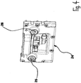
- connection plate 24 On its front side opposite the housing end wall 7, the housing assembly 12, 13, 14 of the battery module 1 is closed by means of a connection plate 24.
- the connection plate 24 is provided with a connection terminal 25 or 26 for each of the two busbars of the battery unit 2.
- the two connection terminals 25, 26 are each formed as a double-nut connection and connectable to their outer sides with a comparatively small technical and design effort to electrical elements.
- connection plate 24 On the inside of the connection plate 24 whose connection terminals 25, 26 associated with them terminal ends of the two bus bars of the battery module 1 and der Batterieisme 2 strig.
- the cell connectors 6 of the battery module 1 are, as best of the Figures 2 and 7 emerges composed of a contact member 27 and a connecting member 32nd
- the contact member 27 serves to connect two battery cells 3 of the battery unit 2 to each other and for this purpose has a first contact portion 28 which is connectable to a cell terminal 29 of a battery cell 3, and a second contact portion 30 which is connectable to a cell terminal 29 of the other battery cell 3 is. Between the first contact portion 28 and the second contact portion 30 of the contact member 27, a compensation portion 31 is formed. By means of this compensation section ud.dgl are due to temperature changes. occurring positional and manufacturing deviations between the fixed and by means of the cell connector 6 to be connected to each other battery cells 3 compensated.
- connection member 32 of the contact member 27 serves the electrical or control technology connection of the cell connector 6 to the control board 4 of the control module 4, 5.
- the connection member 32 is attached to the contact member 27 of the cell connector 6.
- status parameters of the battery cells 3 of the battery module 2 of the battery module connected to the respective contact element 27 can be forwarded to the control board 4 of the control module 4, 5 of the battery module 1. Accordingly, due to these forwarded to the control board status parameters unequal states of charge between the two by the relevant contact member 27 of the cell connector 6 connected to each other battery cells 3 of the battery module can be compensated, which is preferably done automatically in the illustrated embodiment.
- the connecting member 32 is designed with a flexibility that is considerably larger compared to that of the contact member 27.
- FIG. 1 shows that the control board 4, 5 of the control module 4 and the support frame 5, 5 of the battery module 1 rests on the top of the battery unit 2.
- a housing cover 34 is arranged, by means of which the housing or the housing assembly 12, 13, 14 of the battery module 1 is lockable at the top thereof.
- the above-described battery modules 1 can be assembled to any number of such battery modules 1 having battery arrangements.
- a battery arrangement whose battery modules 1 are connected to one another to include subunits each having a plurality of battery modules 1, which are arranged spatially separated from one another.
Landscapes
- Chemical & Material Sciences (AREA)
- Chemical Kinetics & Catalysis (AREA)
- Electrochemistry (AREA)
- General Chemical & Material Sciences (AREA)
- Engineering & Computer Science (AREA)
- Manufacturing & Machinery (AREA)
- Battery Mounting, Suspending (AREA)
- Secondary Cells (AREA)
Claims (14)
- Module de batterie pour un système de batterie présentant une pluralité de tels modules de batterie (1), avec une unité de batterie (2) qui présente une pluralité d'éléments de batterie (3) reliés les uns aux autres, un module de boîtier (12, 13, 14) avec une plaque de base (12) et deux parois latérales (13, 14) disposées de manière située en vis-à-vis l'une de l'autre qui peuvent être reliées, de préférence au moyen de raccords vissés (19), avec la plaque de base (12), une coque de réception (20) qui est formée en plastique, repose sur le côté intérieur de la plaque de base (12) et présente sur ses côtés longitudinaux des bords repliés (21, 22) saillants en direction vers le haut entre lesquels une partie inférieure de l'unité de batterie (2) du module de batterie (1) peut être réceptionnée, et un couvercle de boîtier (34), caractérisé en ce que le module de batterie (1) possède un module de commande (4, 5) qui présente une platine de commande (4) pour la surveillance et le réglage du fonctionnement de l'unité de batterie (2) et un cadre de support (5), lequel est monté sur l'unité de batterie (2) et au niveau duquel des connecteurs d'éléments (6) sont disposés, au moyen desquels il est possible de respectivement relier entre eux deux éléments de batterie (3) de l'unité de batterie (2), que le module de commande (4, 5) est disposé avec sa platine de commande (4) et son cadre de support (5) entre le côté supérieur de l'unité de batterie (2) et le couvercle de boîtier (34), et que les parois latérales (13, 14) présentent, au niveau de leurs bords longitudinaux inférieurs (15) sur leur côté intérieur, des saillies longitudinales (16) qui se mettent en prise avec des évidements longitudinaux (18) réalisés au niveau de bords longitudinaux (17) associés de la plaque de base (12).
- Module de batterie selon la revendication 1, dont les parois latérales (13, 14) sont réalisées avec une pluralité d'ailettes de refroidissement (23) sur leur surface extérieure.
- Module de batterie selon la revendication 1 ou 2, dont les parois latérales (13, 14) sont refroidies à l'eau.
- Module de batterie selon la revendication 1 ou 2, dont les parois latérales (13, 14) sont refroidies à l'air.
- Module de batterie selon l'une des revendications 1 à 4, dans lequel la paroi latérale (14, 13) présente une structure spatiale avec au moins une partie saillante (35, 37) et au moins une partie évidée (36, 38), laquelle convient pour se mettre en prise avec l'au moins une partie évidée (36, 38) de la paroi latérale (13, 14) associée d'un module de batterie (1) voisin ou pour la mise en prise dans laquelle l'au moins une partie saillante (35, 37) de la paroi latérale (13, 14) associée d'un module de batterie (1) voisin convient.
- Module de batterie selon la revendication 5, dans lequel la structure spatiale des parois latérales (13, 14) est réalisée de manière complémentaire à celle des parois latérales (14, 13) de modules de batterie (1) voisins.
- Module de batterie selon l'une des revendications 1 à 6, avec une plaque de raccordement (24) au moyen de laquelle le module de boîtier (12, 13, 14) du module de batterie (1) peut être fermé au niveau d'un côté frontal de ce ou ces mêmes et qui présente une borne de raccordement (25, 26) pour chacune des deux barres conductrices du module de batterie (1), dans lequel chaque borne de raccordement (25, 26) est réalisée en tant qu'assemblage à double écrou et peut être raccordée sur son côté extérieur.
- Module de batterie selon la revendication 7, dont la plaque de raccordement (24) peut être vissée au niveau de ses bornes de raccordement (25, 26) sur des extrémités de raccordement des barres conductrices du module de batterie (1).
- Module de batterie selon l'une des revendications 1 à 8, dans lequel chaque connecteur d'élément (6) possède un organe de contact (27) qui sert au raccordement de deux éléments de batterie (3) entre eux et présente à cet effet une première partie de contact (28) qui peut être raccordée à une borne d'élément (29) de l'un des éléments de batterie (3), une deuxième partie de contact (30) qui peut être raccordée à une borne d'élément (29) de l'autre élément de batterie (3), et une partie de compensation (31) qui est disposée entre la première (28) et la deuxième partie de contact (30) et au moyen de laquelle il est possible de compenser des différences de fabrication et de position entre les éléments de batterie (3) fixés et à raccorder entre eux au moyen du connecteur d'éléments (6), et un organe de raccordement (32) au moyen duquel le connecteur d'éléments (6) peut être raccordé à la platine de commande (4) du module de commande (4, 5) du module de batterie (1), lequel est agencé sur l'organe de contact (27) du connecteur d'éléments (6), au moyen duquel des paramètres d'état des éléments de batterie (3) peuvent être retransmis à la platine de commande (4) du module de commande (4, 5) du module de batterie (1), au moyen duquel, en coopération avec la platine de commande (4), il est possible de compenser de préférence automatiquement des états de charge inégaux entre les deux éléments de batterie (3) du module de batterie (1) raccordés entre eux grâce à l'organe de contact (27) du connecteur d'éléments (6), et dont la flexibilité est nettement supérieure en comparaison avec celle de l'organe de contact (27).
- Module de batterie selon la revendication 9, dans la platine de commande (4) duquel il est possible de surveiller la température de chaque élément de batterie (3).
- Module de batterie selon l'une des revendications 1 à 10, dans lequel un film isolant (33) est disposé entre les éléments de batterie (3) de l'unité de batterie (2) au moyen duquel il est possible d'isoler électriquement les uns par rapport aux autres les éléments de batterie (3) individuels de l'unité de batterie (2).
- Système de batterie à base d'une pluralité de modules de batterie (1) selon l'une des revendications 1 à 11, dans lequel les modules de batterie (1) individuels sont disposés en unités partielles séparées spatialement les unes des autres.
- Module de batterie selon l'une des revendications 1 à 11, dans lequel l'unité de batterie (2) repose avec une paroi frontale contre une paroi frontale de boîtier (7) disposée de manière fixe par rapport à un boîtier (12, 13, 14) du module de batterie (1), et au niveau de la paroi frontale de l'unité de batterie (2) éloignée de la paroi frontale de boîtier fixe (7) un organe de serrage (8) étant disposé, lequel peut être déplacé en direction longitudinale de l'unité de batterie (2) vers la paroi frontale de boîtier fixe (7) .
- Module de batterie selon la revendication 13, entre la paroi frontale de boîtier fixe (7) duquel et l'organe de serrage (8) duquel des tiges (9) sont disposées, lesquelles présentent, du côté d'organe de serrage, des parties filetées (10) avec des écrous de serrage (11) au moyen desquels il est possible de déplacer l'organe de serrage (8) en direction de la paroi frontale de boîtier fixe (7).
Priority Applications (2)
| Application Number | Priority Date | Filing Date | Title |
|---|---|---|---|
| PL17000464T PL3214670T3 (pl) | 2015-05-13 | 2016-04-15 | Moduł akumulatorowy do zespołów akumulatorowych, zawierających dużą ilość tego rodzaju modułów akumulatorowych |
| HRP20200316TT HRP20200316T1 (hr) | 2015-05-13 | 2020-02-25 | Baterijski modul za baterijske uređaje koji sadrže veći broj takvih baterijskih modula |
Applications Claiming Priority (2)
| Application Number | Priority Date | Filing Date | Title |
|---|---|---|---|
| DE102015006168.2A DE102015006168A1 (de) | 2015-05-13 | 2015-05-13 | Batteriemodul für eine Mehrzahl derartiger Batteriemodule aufweisende Batterieanordnungen |
| EP16000856.1A EP3093901B1 (fr) | 2015-05-13 | 2016-04-15 | Module de batterie pour des systemes de batterie comprenant une pluralite des tels modules de batterie |
Related Parent Applications (2)
| Application Number | Title | Priority Date | Filing Date |
|---|---|---|---|
| EP16000856.1A Division-Into EP3093901B1 (fr) | 2015-05-13 | 2016-04-15 | Module de batterie pour des systemes de batterie comprenant une pluralite des tels modules de batterie |
| EP16000856.1A Division EP3093901B1 (fr) | 2015-05-13 | 2016-04-15 | Module de batterie pour des systemes de batterie comprenant une pluralite des tels modules de batterie |
Publications (3)
| Publication Number | Publication Date |
|---|---|
| EP3214670A2 EP3214670A2 (fr) | 2017-09-06 |
| EP3214670A3 EP3214670A3 (fr) | 2017-11-22 |
| EP3214670B1 true EP3214670B1 (fr) | 2019-12-04 |
Family
ID=55759438
Family Applications (2)
| Application Number | Title | Priority Date | Filing Date |
|---|---|---|---|
| EP17000464.2A Active EP3214670B1 (fr) | 2015-05-13 | 2016-04-15 | Module de batterie pour un système de batterie comprenant une pluralité de tels modules de batterie |
| EP16000856.1A Active EP3093901B1 (fr) | 2015-05-13 | 2016-04-15 | Module de batterie pour des systemes de batterie comprenant une pluralite des tels modules de batterie |
Family Applications After (1)
| Application Number | Title | Priority Date | Filing Date |
|---|---|---|---|
| EP16000856.1A Active EP3093901B1 (fr) | 2015-05-13 | 2016-04-15 | Module de batterie pour des systemes de batterie comprenant une pluralite des tels modules de batterie |
Country Status (4)
| Country | Link |
|---|---|
| EP (2) | EP3214670B1 (fr) |
| DE (1) | DE102015006168A1 (fr) |
| HR (2) | HRP20200132T1 (fr) |
| PL (2) | PL3214670T3 (fr) |
Families Citing this family (6)
| Publication number | Priority date | Publication date | Assignee | Title |
|---|---|---|---|---|
| DE102017130556B4 (de) * | 2017-12-19 | 2019-08-08 | Webasto SE | Batterieanordnung |
| DE102018002334B3 (de) * | 2018-03-21 | 2019-07-18 | Voltabox Ag | Batteriezelleneinheit für Batteriemodule |
| CN112310525A (zh) * | 2019-08-14 | 2021-02-02 | 宁德时代新能源科技股份有限公司 | 电池箱 |
| CN111599957A (zh) * | 2020-04-27 | 2020-08-28 | 威睿电动汽车技术(宁波)有限公司 | 一种电池模组及电池包 |
| DE102020005872A1 (de) * | 2020-09-25 | 2022-03-31 | Voltabox Ag | Elektrobatterie für ein elektrisch oder teilelektrisch angetriebenes Kraftfahrzeug, verfahrbares oder stationäres Aggregat |
| CN113675522B (zh) * | 2021-08-19 | 2023-07-28 | 福建云众动力科技有限公司 | 一种适合水中设备使用的锂电池 |
Family Cites Families (8)
| Publication number | Priority date | Publication date | Assignee | Title |
|---|---|---|---|---|
| WO2011092773A1 (fr) * | 2010-01-29 | 2011-08-04 | パナソニック株式会社 | Module de pile |
| DE102011075044A1 (de) * | 2011-05-02 | 2012-11-08 | Schaeffler Technologies AG & Co. KG | Batteriegehäuse |
| JP2013025983A (ja) * | 2011-07-20 | 2013-02-04 | Sanyo Electric Co Ltd | 電源装置及び電源装置を備える車両 |
| US10033072B2 (en) * | 2012-01-05 | 2018-07-24 | Electrovaya Inc. | Fluid-cooled battery module containing battery cells |
| JP2014035970A (ja) * | 2012-08-10 | 2014-02-24 | Honda Motor Co Ltd | 蓄電装置 |
| DE102013204180B4 (de) * | 2013-03-12 | 2021-07-08 | Robert Bosch Gmbh | Einhausung zum Aufnehmen eines Zellpakets, Batterie, Verfahren zum Herstellen einer Batterie und Verfahren zum Herstellen eines faserverstärkten Kunststoffbauteils für eine Einhausung einer Batterie |
| DE102013213540A1 (de) * | 2013-07-10 | 2015-01-15 | Robert Bosch Gmbh | Batterie mit einem Zellverbinder, Kraftfahrzeug mit der Batterie sowie Verfahren zur Herstellung der Batterie |
| CN204315644U (zh) * | 2014-12-05 | 2015-05-06 | 天津市华恒天成科技有限公司 | 一种拼接结构蓄电池盒 |
-
2015
- 2015-05-13 DE DE102015006168.2A patent/DE102015006168A1/de not_active Withdrawn
-
2016
- 2016-04-15 PL PL17000464T patent/PL3214670T3/pl unknown
- 2016-04-15 EP EP17000464.2A patent/EP3214670B1/fr active Active
- 2016-04-15 PL PL16000856T patent/PL3093901T3/pl unknown
- 2016-04-15 EP EP16000856.1A patent/EP3093901B1/fr active Active
-
2020
- 2020-01-28 HR HRP20200132TT patent/HRP20200132T1/hr unknown
- 2020-02-25 HR HRP20200316TT patent/HRP20200316T1/hr unknown
Non-Patent Citations (1)
| Title |
|---|
| None * |
Also Published As
| Publication number | Publication date |
|---|---|
| DE102015006168A1 (de) | 2016-11-17 |
| PL3214670T3 (pl) | 2020-06-01 |
| HRP20200316T1 (hr) | 2020-06-12 |
| EP3093901B1 (fr) | 2019-11-06 |
| HRP20200132T1 (hr) | 2020-05-15 |
| EP3214670A2 (fr) | 2017-09-06 |
| EP3214670A3 (fr) | 2017-11-22 |
| EP3093901A3 (fr) | 2016-12-14 |
| EP3093901A2 (fr) | 2016-11-16 |
| PL3093901T3 (pl) | 2020-05-18 |
Similar Documents
| Publication | Publication Date | Title |
|---|---|---|
| EP3093901B1 (fr) | Module de batterie pour des systemes de batterie comprenant une pluralite des tels modules de batterie | |
| DE102009023607B4 (de) | Verteiler für elektrische Leistung mit Stromsensor | |
| DE102008059967B4 (de) | Batterie und Verfahren zur Herstellung einer Batterie mit einer in einem Batteriegehäuse angeordneten Wärmeleitplatte | |
| DE112022000452T5 (de) | Karosseriebodenbaugruppe für Fahrzeug und Fahrzeug | |
| DE102015119333B4 (de) | Anschlussklemmenleisteneinheit | |
| DE102013207536B4 (de) | Zellblock mit Zellfixierung für eine Batterie und Verfahren zum Bestücken eines Zellblocks | |
| DE102011076324B4 (de) | Leistungselektronisches System mit Verbindungseinrichtung erster und zweiter Subsysteme | |
| DE69400534T2 (de) | Verbindungsstruktur zum elektrischen Verbinden von Elektromotor und Motorregeleinheit | |
| DE112009002352T5 (de) | Energiespeichereinheit | |
| EP0051315A2 (fr) | Ensemble d'éléments semi-conducteurs | |
| DE102012202059A1 (de) | Sicherungsanordnung | |
| DE112014005950T5 (de) | Elektronische Vorrichtung mit Kühlfunktion | |
| DE102006032258A1 (de) | Elektrischer Verbinderkasten für Kraftfahrzeuge | |
| EP2826114A1 (fr) | Unité de montage et procédé de montage d'un rail de montage sur une plaque de montage pour une armoire électrique | |
| WO2017182129A1 (fr) | Système d'entraînement comprenant une barre conductrice de circuit intermédiaire | |
| EP2091113B1 (fr) | Système de raccordement pour bandes lumineuses ou lampes | |
| DE102015217790A1 (de) | Anordnung zur Kühlung von Batteriezellen eines Antriebsenergiespeichers eines Kraftfahrzeuges | |
| DE102018125283B4 (de) | Batteriemodul | |
| WO2018108498A1 (fr) | Élément de découplage servant à relier une électronique de puissance à une machine électrique | |
| EP2270821B1 (fr) | Eolienne dotée d'un onduleur et d'au moins une résistance haute tension | |
| DE102017127895A1 (de) | Wechselrichter für Elektromotor | |
| EP3799238A1 (fr) | Système des barres conductrices | |
| DE202012006447U1 (de) | Vorrichtung zur Spannungsversorgung eines Kraftfahrzeugs mit einem Kühlerblock | |
| DE102008064499B4 (de) | Variable Anschlussvorrichtung für eine elektrische Maschine | |
| DE202010008274U1 (de) | Elektrische Verbindung zwischen zwei Busbars aus ebenen Leitern und einer zwischen den Leitern angeordneten Isolationsschicht |
Legal Events
| Date | Code | Title | Description |
|---|---|---|---|
| PUAI | Public reference made under article 153(3) epc to a published international application that has entered the european phase |
Free format text: ORIGINAL CODE: 0009012 |
|
| STAA | Information on the status of an ep patent application or granted ep patent |
Free format text: STATUS: THE APPLICATION HAS BEEN PUBLISHED |
|
| AC | Divisional application: reference to earlier application |
Ref document number: 3093901 Country of ref document: EP Kind code of ref document: P |
|
| AK | Designated contracting states |
Kind code of ref document: A2 Designated state(s): AL AT BE BG CH CY CZ DE DK EE ES FI FR GB GR HR HU IE IS IT LI LT LU LV MC MK MT NL NO PL PT RO RS SE SI SK SM TR |
|
| AX | Request for extension of the european patent |
Extension state: BA ME |
|
| PUAL | Search report despatched |
Free format text: ORIGINAL CODE: 0009013 |
|
| AK | Designated contracting states |
Kind code of ref document: A3 Designated state(s): AL AT BE BG CH CY CZ DE DK EE ES FI FR GB GR HR HU IE IS IT LI LT LU LV MC MK MT NL NO PL PT RO RS SE SI SK SM TR |
|
| AX | Request for extension of the european patent |
Extension state: BA ME |
|
| RIC1 | Information provided on ipc code assigned before grant |
Ipc: H01M 2/20 20060101ALI20171017BHEP Ipc: H01M 10/613 20140101ALI20171017BHEP Ipc: H01M 10/625 20140101ALI20171017BHEP Ipc: H01M 10/42 20060101ALN20171017BHEP Ipc: H01M 2/10 20060101AFI20171017BHEP Ipc: H01M 10/6554 20140101ALI20171017BHEP Ipc: H01M 10/647 20140101ALI20171017BHEP |
|
| STAA | Information on the status of an ep patent application or granted ep patent |
Free format text: STATUS: REQUEST FOR EXAMINATION WAS MADE |
|
| 17P | Request for examination filed |
Effective date: 20180424 |
|
| RBV | Designated contracting states (corrected) |
Designated state(s): AL AT BE BG CH CY CZ DE DK EE ES FI FR GB GR HR HU IE IS IT LI LT LU LV MC MK MT NL NO PL PT RO RS SE SI SK SM TR |
|
| STAA | Information on the status of an ep patent application or granted ep patent |
Free format text: STATUS: EXAMINATION IS IN PROGRESS |
|
| 17Q | First examination report despatched |
Effective date: 20180724 |
|
| GRAP | Despatch of communication of intention to grant a patent |
Free format text: ORIGINAL CODE: EPIDOSNIGR1 |
|
| STAA | Information on the status of an ep patent application or granted ep patent |
Free format text: STATUS: GRANT OF PATENT IS INTENDED |
|
| RIC1 | Information provided on ipc code assigned before grant |
Ipc: H01M 10/6554 20140101ALI20190529BHEP Ipc: H01M 2/20 20060101ALI20190529BHEP Ipc: H01M 10/613 20140101ALI20190529BHEP Ipc: H01M 10/625 20140101ALI20190529BHEP Ipc: H01M 10/647 20140101ALI20190529BHEP Ipc: H01M 2/10 20060101AFI20190529BHEP Ipc: H01M 10/42 20060101ALN20190529BHEP |
|
| RIC1 | Information provided on ipc code assigned before grant |
Ipc: H01M 10/6554 20140101ALI20190604BHEP Ipc: H01M 10/42 20060101ALN20190604BHEP Ipc: H01M 2/20 20060101ALI20190604BHEP Ipc: H01M 10/647 20140101ALN20190604BHEP Ipc: H01M 2/10 20060101AFI20190604BHEP Ipc: H01M 10/613 20140101ALI20190604BHEP Ipc: H01M 10/625 20140101ALN20190604BHEP |
|
| INTG | Intention to grant announced |
Effective date: 20190619 |
|
| GRAS | Grant fee paid |
Free format text: ORIGINAL CODE: EPIDOSNIGR3 |
|
| GRAA | (expected) grant |
Free format text: ORIGINAL CODE: 0009210 |
|
| STAA | Information on the status of an ep patent application or granted ep patent |
Free format text: STATUS: THE PATENT HAS BEEN GRANTED |
|
| AC | Divisional application: reference to earlier application |
Ref document number: 3093901 Country of ref document: EP Kind code of ref document: P |
|
| AK | Designated contracting states |
Kind code of ref document: B1 Designated state(s): AL AT BE BG CH CY CZ DE DK EE ES FI FR GB GR HR HU IE IS IT LI LT LU LV MC MK MT NL NO PL PT RO RS SE SI SK SM TR |
|
| REG | Reference to a national code |
Ref country code: GB Ref legal event code: FG4D Free format text: NOT ENGLISH |
|
| REG | Reference to a national code |
Ref country code: CH Ref legal event code: EP |
|
| REG | Reference to a national code |
Ref country code: AT Ref legal event code: REF Ref document number: 1210527 Country of ref document: AT Kind code of ref document: T Effective date: 20191215 |
|
| REG | Reference to a national code |
Ref country code: DE Ref legal event code: R096 Ref document number: 502016007932 Country of ref document: DE |
|
| REG | Reference to a national code |
Ref country code: IE Ref legal event code: FG4D Free format text: LANGUAGE OF EP DOCUMENT: GERMAN |
|
| REG | Reference to a national code |
Ref country code: HR Ref legal event code: TUEP Ref document number: P20200316 Country of ref document: HR |
|
| REG | Reference to a national code |
Ref country code: SE Ref legal event code: TRGR |
|
| REG | Reference to a national code |
Ref country code: NL Ref legal event code: MP Effective date: 20191204 |
|
| REG | Reference to a national code |
Ref country code: LT Ref legal event code: MG4D |
|
| PG25 | Lapsed in a contracting state [announced via postgrant information from national office to epo] |
Ref country code: GR Free format text: LAPSE BECAUSE OF FAILURE TO SUBMIT A TRANSLATION OF THE DESCRIPTION OR TO PAY THE FEE WITHIN THE PRESCRIBED TIME-LIMIT Effective date: 20200305 Ref country code: NO Free format text: LAPSE BECAUSE OF FAILURE TO SUBMIT A TRANSLATION OF THE DESCRIPTION OR TO PAY THE FEE WITHIN THE PRESCRIBED TIME-LIMIT Effective date: 20200304 Ref country code: BG Free format text: LAPSE BECAUSE OF FAILURE TO SUBMIT A TRANSLATION OF THE DESCRIPTION OR TO PAY THE FEE WITHIN THE PRESCRIBED TIME-LIMIT Effective date: 20200304 Ref country code: LT Free format text: LAPSE BECAUSE OF FAILURE TO SUBMIT A TRANSLATION OF THE DESCRIPTION OR TO PAY THE FEE WITHIN THE PRESCRIBED TIME-LIMIT Effective date: 20191204 Ref country code: FI Free format text: LAPSE BECAUSE OF FAILURE TO SUBMIT A TRANSLATION OF THE DESCRIPTION OR TO PAY THE FEE WITHIN THE PRESCRIBED TIME-LIMIT Effective date: 20191204 Ref country code: LV Free format text: LAPSE BECAUSE OF FAILURE TO SUBMIT A TRANSLATION OF THE DESCRIPTION OR TO PAY THE FEE WITHIN THE PRESCRIBED TIME-LIMIT Effective date: 20191204 |
|
| PG25 | Lapsed in a contracting state [announced via postgrant information from national office to epo] |
Ref country code: RS Free format text: LAPSE BECAUSE OF FAILURE TO SUBMIT A TRANSLATION OF THE DESCRIPTION OR TO PAY THE FEE WITHIN THE PRESCRIBED TIME-LIMIT Effective date: 20191204 |
|
| REG | Reference to a national code |
Ref country code: HR Ref legal event code: ODRP Ref document number: P20200316 Country of ref document: HR Payment date: 20200406 Year of fee payment: 5 |
|
| REG | Reference to a national code |
Ref country code: HR Ref legal event code: T1PR Ref document number: P20200316 Country of ref document: HR |
|
| PG25 | Lapsed in a contracting state [announced via postgrant information from national office to epo] |
Ref country code: AL Free format text: LAPSE BECAUSE OF FAILURE TO SUBMIT A TRANSLATION OF THE DESCRIPTION OR TO PAY THE FEE WITHIN THE PRESCRIBED TIME-LIMIT Effective date: 20191204 |
|
| PG25 | Lapsed in a contracting state [announced via postgrant information from national office to epo] |
Ref country code: ES Free format text: LAPSE BECAUSE OF FAILURE TO SUBMIT A TRANSLATION OF THE DESCRIPTION OR TO PAY THE FEE WITHIN THE PRESCRIBED TIME-LIMIT Effective date: 20191204 Ref country code: NL Free format text: LAPSE BECAUSE OF FAILURE TO SUBMIT A TRANSLATION OF THE DESCRIPTION OR TO PAY THE FEE WITHIN THE PRESCRIBED TIME-LIMIT Effective date: 20191204 Ref country code: CZ Free format text: LAPSE BECAUSE OF FAILURE TO SUBMIT A TRANSLATION OF THE DESCRIPTION OR TO PAY THE FEE WITHIN THE PRESCRIBED TIME-LIMIT Effective date: 20191204 Ref country code: RO Free format text: LAPSE BECAUSE OF FAILURE TO SUBMIT A TRANSLATION OF THE DESCRIPTION OR TO PAY THE FEE WITHIN THE PRESCRIBED TIME-LIMIT Effective date: 20191204 Ref country code: EE Free format text: LAPSE BECAUSE OF FAILURE TO SUBMIT A TRANSLATION OF THE DESCRIPTION OR TO PAY THE FEE WITHIN THE PRESCRIBED TIME-LIMIT Effective date: 20191204 Ref country code: PT Free format text: LAPSE BECAUSE OF FAILURE TO SUBMIT A TRANSLATION OF THE DESCRIPTION OR TO PAY THE FEE WITHIN THE PRESCRIBED TIME-LIMIT Effective date: 20200429 |
|
| PGFP | Annual fee paid to national office [announced via postgrant information from national office to epo] |
Ref country code: CH Payment date: 20200423 Year of fee payment: 5 Ref country code: FR Payment date: 20200421 Year of fee payment: 5 |
|
| PG25 | Lapsed in a contracting state [announced via postgrant information from national office to epo] |
Ref country code: IS Free format text: LAPSE BECAUSE OF FAILURE TO SUBMIT A TRANSLATION OF THE DESCRIPTION OR TO PAY THE FEE WITHIN THE PRESCRIBED TIME-LIMIT Effective date: 20200404 Ref country code: SM Free format text: LAPSE BECAUSE OF FAILURE TO SUBMIT A TRANSLATION OF THE DESCRIPTION OR TO PAY THE FEE WITHIN THE PRESCRIBED TIME-LIMIT Effective date: 20191204 Ref country code: SK Free format text: LAPSE BECAUSE OF FAILURE TO SUBMIT A TRANSLATION OF THE DESCRIPTION OR TO PAY THE FEE WITHIN THE PRESCRIBED TIME-LIMIT Effective date: 20191204 |
|
| PGFP | Annual fee paid to national office [announced via postgrant information from national office to epo] |
Ref country code: GB Payment date: 20200423 Year of fee payment: 5 Ref country code: PL Payment date: 20200327 Year of fee payment: 5 Ref country code: HR Payment date: 20200406 Year of fee payment: 5 Ref country code: SE Payment date: 20200423 Year of fee payment: 5 Ref country code: IT Payment date: 20200423 Year of fee payment: 5 |
|
| REG | Reference to a national code |
Ref country code: DE Ref legal event code: R097 Ref document number: 502016007932 Country of ref document: DE |
|
| PLBE | No opposition filed within time limit |
Free format text: ORIGINAL CODE: 0009261 |
|
| STAA | Information on the status of an ep patent application or granted ep patent |
Free format text: STATUS: NO OPPOSITION FILED WITHIN TIME LIMIT |
|
| PG25 | Lapsed in a contracting state [announced via postgrant information from national office to epo] |
Ref country code: DK Free format text: LAPSE BECAUSE OF FAILURE TO SUBMIT A TRANSLATION OF THE DESCRIPTION OR TO PAY THE FEE WITHIN THE PRESCRIBED TIME-LIMIT Effective date: 20191204 |
|
| PGFP | Annual fee paid to national office [announced via postgrant information from national office to epo] |
Ref country code: DE Payment date: 20200710 Year of fee payment: 5 |
|
| 26N | No opposition filed |
Effective date: 20200907 |
|
| REG | Reference to a national code |
Ref country code: DE Ref legal event code: R079 Ref document number: 502016007932 Country of ref document: DE Free format text: PREVIOUS MAIN CLASS: H01M0002100000 Ipc: H01M0050200000 |
|
| PG25 | Lapsed in a contracting state [announced via postgrant information from national office to epo] |
Ref country code: SI Free format text: LAPSE BECAUSE OF FAILURE TO SUBMIT A TRANSLATION OF THE DESCRIPTION OR TO PAY THE FEE WITHIN THE PRESCRIBED TIME-LIMIT Effective date: 20191204 Ref country code: MC Free format text: LAPSE BECAUSE OF FAILURE TO SUBMIT A TRANSLATION OF THE DESCRIPTION OR TO PAY THE FEE WITHIN THE PRESCRIBED TIME-LIMIT Effective date: 20191204 |
|
| PG25 | Lapsed in a contracting state [announced via postgrant information from national office to epo] |
Ref country code: LU Free format text: LAPSE BECAUSE OF NON-PAYMENT OF DUE FEES Effective date: 20200415 |
|
| REG | Reference to a national code |
Ref country code: BE Ref legal event code: MM Effective date: 20200430 |
|
| PG25 | Lapsed in a contracting state [announced via postgrant information from national office to epo] |
Ref country code: BE Free format text: LAPSE BECAUSE OF NON-PAYMENT OF DUE FEES Effective date: 20200430 |
|
| PG25 | Lapsed in a contracting state [announced via postgrant information from national office to epo] |
Ref country code: IE Free format text: LAPSE BECAUSE OF NON-PAYMENT OF DUE FEES Effective date: 20200415 |
|
| REG | Reference to a national code |
Ref country code: HR Ref legal event code: PBON Ref document number: P20200316 Country of ref document: HR Effective date: 20210415 |
|
| REG | Reference to a national code |
Ref country code: DE Ref legal event code: R119 Ref document number: 502016007932 Country of ref document: DE |
|
| REG | Reference to a national code |
Ref country code: SE Ref legal event code: EUG |
|
| GBPC | Gb: european patent ceased through non-payment of renewal fee |
Effective date: 20210415 |
|
| PG25 | Lapsed in a contracting state [announced via postgrant information from national office to epo] |
Ref country code: SE Free format text: LAPSE BECAUSE OF NON-PAYMENT OF DUE FEES Effective date: 20210416 Ref country code: DE Free format text: LAPSE BECAUSE OF NON-PAYMENT OF DUE FEES Effective date: 20211103 Ref country code: CH Free format text: LAPSE BECAUSE OF NON-PAYMENT OF DUE FEES Effective date: 20210430 Ref country code: LI Free format text: LAPSE BECAUSE OF NON-PAYMENT OF DUE FEES Effective date: 20210430 Ref country code: HR Free format text: LAPSE BECAUSE OF NON-PAYMENT OF DUE FEES Effective date: 20210415 Ref country code: FR Free format text: LAPSE BECAUSE OF NON-PAYMENT OF DUE FEES Effective date: 20210430 Ref country code: GB Free format text: LAPSE BECAUSE OF NON-PAYMENT OF DUE FEES Effective date: 20210415 |
|
| PG25 | Lapsed in a contracting state [announced via postgrant information from national office to epo] |
Ref country code: TR Free format text: LAPSE BECAUSE OF FAILURE TO SUBMIT A TRANSLATION OF THE DESCRIPTION OR TO PAY THE FEE WITHIN THE PRESCRIBED TIME-LIMIT Effective date: 20191204 Ref country code: MT Free format text: LAPSE BECAUSE OF FAILURE TO SUBMIT A TRANSLATION OF THE DESCRIPTION OR TO PAY THE FEE WITHIN THE PRESCRIBED TIME-LIMIT Effective date: 20191204 Ref country code: CY Free format text: LAPSE BECAUSE OF FAILURE TO SUBMIT A TRANSLATION OF THE DESCRIPTION OR TO PAY THE FEE WITHIN THE PRESCRIBED TIME-LIMIT Effective date: 20191204 |
|
| REG | Reference to a national code |
Ref country code: AT Ref legal event code: MM01 Ref document number: 1210527 Country of ref document: AT Kind code of ref document: T Effective date: 20210415 |
|
| PG25 | Lapsed in a contracting state [announced via postgrant information from national office to epo] |
Ref country code: MK Free format text: LAPSE BECAUSE OF FAILURE TO SUBMIT A TRANSLATION OF THE DESCRIPTION OR TO PAY THE FEE WITHIN THE PRESCRIBED TIME-LIMIT Effective date: 20191204 |
|
| PG25 | Lapsed in a contracting state [announced via postgrant information from national office to epo] |
Ref country code: AT Free format text: LAPSE BECAUSE OF NON-PAYMENT OF DUE FEES Effective date: 20210415 |
|
| PG25 | Lapsed in a contracting state [announced via postgrant information from national office to epo] |
Ref country code: PL Free format text: LAPSE BECAUSE OF NON-PAYMENT OF DUE FEES Effective date: 20210415 Ref country code: IT Free format text: LAPSE BECAUSE OF NON-PAYMENT OF DUE FEES Effective date: 20200415 |
|
| PG25 | Lapsed in a contracting state [announced via postgrant information from national office to epo] |
Ref country code: IT Free format text: LAPSE BECAUSE OF NON-PAYMENT OF DUE FEES Effective date: 20210415 |