EP3214761A2 - Vibreur électronique - Google Patents
Vibreur électronique Download PDFInfo
- Publication number
- EP3214761A2 EP3214761A2 EP15854181.3A EP15854181A EP3214761A2 EP 3214761 A2 EP3214761 A2 EP 3214761A2 EP 15854181 A EP15854181 A EP 15854181A EP 3214761 A2 EP3214761 A2 EP 3214761A2
- Authority
- EP
- European Patent Office
- Prior art keywords
- transistor
- core
- bridge circuit
- power
- unit
- Prior art date
- Legal status (The legal status is an assumption and is not a legal conclusion. Google has not performed a legal analysis and makes no representation as to the accuracy of the status listed.)
- Withdrawn
Links
- JOYRKODLDBILNP-UHFFFAOYSA-N Ethyl urethane Chemical compound CCOC(N)=O JOYRKODLDBILNP-UHFFFAOYSA-N 0.000 claims abstract description 11
- 238000004804 winding Methods 0.000 claims abstract description 11
- 229910000831 Steel Inorganic materials 0.000 claims abstract description 6
- 239000010959 steel Substances 0.000 claims abstract description 6
- 230000003139 buffering effect Effects 0.000 claims abstract description 3
- 229910000976 Electrical steel Inorganic materials 0.000 claims description 3
- 230000000149 penetrating effect Effects 0.000 claims 1
- 239000000843 powder Substances 0.000 abstract description 25
- 238000001179 sorption measurement Methods 0.000 abstract description 8
- 238000004519 manufacturing process Methods 0.000 abstract description 4
- 230000000694 effects Effects 0.000 abstract description 2
- 230000002265 prevention Effects 0.000 abstract 2
- 238000005054 agglomeration Methods 0.000 description 6
- 230000002776 aggregation Effects 0.000 description 6
- 238000010586 diagram Methods 0.000 description 4
- 230000004907 flux Effects 0.000 description 3
- 238000000034 method Methods 0.000 description 3
- 238000010298 pulverizing process Methods 0.000 description 3
- 239000003463 adsorbent Substances 0.000 description 2
- 239000000463 material Substances 0.000 description 2
- 239000003990 capacitor Substances 0.000 description 1
- 238000004140 cleaning Methods 0.000 description 1
- 238000010276 construction Methods 0.000 description 1
- 238000007796 conventional method Methods 0.000 description 1
- 230000002542 deteriorative effect Effects 0.000 description 1
- 230000005611 electricity Effects 0.000 description 1
- 230000005674 electromagnetic induction Effects 0.000 description 1
- 238000009499 grossing Methods 0.000 description 1
- 238000009434 installation Methods 0.000 description 1
- 238000012423 maintenance Methods 0.000 description 1
- 230000007257 malfunction Effects 0.000 description 1
- 238000012986 modification Methods 0.000 description 1
- 230000004048 modification Effects 0.000 description 1
- 239000013618 particulate matter Substances 0.000 description 1
- 230000000704 physical effect Effects 0.000 description 1
- 230000003068 static effect Effects 0.000 description 1
Images


Classifications
-
- B—PERFORMING OPERATIONS; TRANSPORTING
- B06—GENERATING OR TRANSMITTING MECHANICAL VIBRATIONS IN GENERAL
- B06B—METHODS OR APPARATUS FOR GENERATING OR TRANSMITTING MECHANICAL VIBRATIONS OF INFRASONIC, SONIC, OR ULTRASONIC FREQUENCY, e.g. FOR PERFORMING MECHANICAL WORK IN GENERAL
- B06B1/00—Methods or apparatus for generating mechanical vibrations of infrasonic, sonic, or ultrasonic frequency
- B06B1/02—Methods or apparatus for generating mechanical vibrations of infrasonic, sonic, or ultrasonic frequency making use of electrical energy
- B06B1/04—Methods or apparatus for generating mechanical vibrations of infrasonic, sonic, or ultrasonic frequency making use of electrical energy operating with electromagnetism
- B06B1/045—Methods or apparatus for generating mechanical vibrations of infrasonic, sonic, or ultrasonic frequency making use of electrical energy operating with electromagnetism using vibrating magnet, armature or coil system
-
- B—PERFORMING OPERATIONS; TRANSPORTING
- B06—GENERATING OR TRANSMITTING MECHANICAL VIBRATIONS IN GENERAL
- B06B—METHODS OR APPARATUS FOR GENERATING OR TRANSMITTING MECHANICAL VIBRATIONS OF INFRASONIC, SONIC, OR ULTRASONIC FREQUENCY, e.g. FOR PERFORMING MECHANICAL WORK IN GENERAL
- B06B1/00—Methods or apparatus for generating mechanical vibrations of infrasonic, sonic, or ultrasonic frequency
- B06B1/02—Methods or apparatus for generating mechanical vibrations of infrasonic, sonic, or ultrasonic frequency making use of electrical energy
- B06B1/0207—Driving circuits
- B06B1/0215—Driving circuits for generating pulses, e.g. bursts of oscillations, envelopes
-
- H—ELECTRICITY
- H02—GENERATION; CONVERSION OR DISTRIBUTION OF ELECTRIC POWER
- H02H—EMERGENCY PROTECTIVE CIRCUIT ARRANGEMENTS
- H02H9/00—Emergency protective circuit arrangements for limiting excess current or voltage without disconnection
- H02H9/02—Emergency protective circuit arrangements for limiting excess current or voltage without disconnection responsive to excess current
-
- H—ELECTRICITY
- H02—GENERATION; CONVERSION OR DISTRIBUTION OF ELECTRIC POWER
- H02K—DYNAMO-ELECTRIC MACHINES
- H02K33/00—Motors with reciprocating, oscillating or vibrating magnet, armature or coil system
- H02K33/16—Motors with reciprocating, oscillating or vibrating magnet, armature or coil system with polarised armatures moving in alternate directions by reversal or energisation of a single coil system
-
- H—ELECTRICITY
- H03—ELECTRONIC CIRCUITRY
- H03K—PULSE TECHNIQUE
- H03K17/00—Electronic switching or gating, i.e. not by contact-making and –breaking
- H03K17/08—Modifications for protecting switching circuit against overcurrent or overvoltage
-
- H—ELECTRICITY
- H03—ELECTRONIC CIRCUITRY
- H03K—PULSE TECHNIQUE
- H03K17/00—Electronic switching or gating, i.e. not by contact-making and –breaking
- H03K17/51—Electronic switching or gating, i.e. not by contact-making and –breaking characterised by the components used
- H03K17/56—Electronic switching or gating, i.e. not by contact-making and –breaking characterised by the components used by the use, as active elements, of semiconductor devices
- H03K17/567—Circuits characterised by the use of more than one type of semiconductor device, e.g. BIMOS, composite devices such as IGBT
-
- B—PERFORMING OPERATIONS; TRANSPORTING
- B02—CRUSHING, PULVERISING, OR DISINTEGRATING; PREPARATORY TREATMENT OF GRAIN FOR MILLING
- B02C—CRUSHING, PULVERISING, OR DISINTEGRATING IN GENERAL; MILLING GRAIN
- B02C19/00—Other disintegrating devices or methods
- B02C19/16—Mills provided with vibrators
Definitions
- the present invention relates to an electronic vibrator, and more specifically to an electronic vibrator pulverizing and scattering powders transferred inside a chute, a hopper or a transferring pipe facility to prevent a sloping discharge opening from being narrowed or clogged due to adsorption or agglomeration of powders inside the discharge opening, increasing and maintaining liquidity of a manufacturing facility so that the powders can be efficiently transferred and supplied from the facility to transferring lines, preventing the sloping discharge opening of the facility from being narrowed or clogged due to adsorption or agglomeration of the powders inside the sloping discharge opening, comparatively easily applying the electronic vibrator to an existing facility to be installed and used, for preventing an excessive flow of electric current due to an increased conduction-time of a power device in an ultra-low frequency operation range, preventing a fracture of the power device due to the excessive flow of electric current, and capable of guaranteeing a stable operation without increasing the current even in the ultra-low frequency operation interval.
- Materials such as powder are typically transferred through transferring pipes and discharge ports of the transferring facilities in construction of various kinds of chutes, hoppers, or transferring pipe facilities for storing and supplying powders or particulate matter used in transportation systems of petrochemical plants.
- the powders located near the lower portion of the outlet may receive a substantial pressure, and the discharge rate at a central portion of the facility is differentiated from that at a side portion of the facility.
- a shear pressure is applied from the central portion to the side portion, and thus the powders are pressurized toward the outlet to be stuck and attached to the outlet.
- the thickness of the adsorbent layer of the powders gradually increases to narrow the passage of the discharge opening. Further, the discharge opening becomes clogged so that the powders cannot be discharged and transferred.
- An economic burden follows because it is required to periodically perform internal maintenance and cleaning of the facility such as frequently checking them, removing powdery adsorbent layers at a lot of manpower and costs.
- Conventional vibration generators use a pulse width modulated (PWM) inverter scheme to increase the driving efficiency. Their operations are stable in an operating frequency range of 40 Hz or more.
- PWM pulse width modulated
- Korean Patent No. 10-1203927 can be referred as a representative example of such techniques.
- the conventional methods have issues; for example, electric current is excessively increased due to an increased conduction time of the power devices in a very low frequency operating range of 40 Hz or less, and thus, the power devices are frequently broken despite current protection and restriction measures.
- the present invention has been proposed to address issues as described above.
- the present invention is purposed to provide an electronic vibrator pulverizing and scattering powders transferred inside a chute, a hopper, or a transferring pipe facility to prevent a sloping discharge opening from being narrowed or clogged due to adsorption or agglomeration of powders inside the discharge opening, increasing and maintaining liquidity of a manufacturing facility so that the powders can be efficiently transferred and supplied from the facility to transferring lines, preventing the sloping discharge opening of the facility from being narrowed or clogged due to adsorption or agglomeration of the powders inside the sloping discharge opening, allowing for relatively easy application, installation, and use of the electronic vibrator in an existing facility, for preventing an excessive flow of electric current due to an increased conduction-time of a power device in an ultra-low frequency operation range, preventing a fracture of the power device due to the excessive flow of electric current, and guaranteeing a stable operation without increasing the current even in the ultra-low
- an electronic vibrator comprises a bridge circuit comprising an insulated-gate bipolar transistor (IGBT) as a power switching device for driving a large-capacity oscillator, a circuit driving unit driving the bridge circuit and applying a sine wave which is a sine wave PWM modulation reference wave as well as a triangular wave, and a vibration generator connected to the bridge circuit, generating vibration by current supplied by the bridge circuit.
- IGBT insulated-gate bipolar transistor
- the bridge circuit comprises a first transistor; a first diode connected in parallel with the first transistor, a second transistor connected in series with the first transistor, a second diode connected in parallel with the second transistor, a third transistor connected in parallel with the first transistor, a third diode connected in parallel with the third transistor, a fourth transistor connected in series with the third transistor, a fourth diode connected in parallel with the fourth transistor, a resistor connected as a start point between the first transistor and the second transistor and as an end point between the third transistor and the fourth transistor, the power source unit 500 applying power to the first transistor and the second transistor, and a ground unit connected to the power source unit 500 and the second transistor, and the fourth transistor.
- the triangular wave is applied to the circuit driving unit using an operational amplifier (OP Amp).
- OP Amp operational amplifier
- an electronic vibrator of the present invention there are effects of pulverizing and scattering powders transferred inside a chute, a hopper, or a transferring pipe facility to prevent a sloping discharge opening from being narrowed or clogged due to adsorption or agglomeration of powders inside the discharge opening, increasing and maintaining liquidity of a manufacturing facility so that the powders can be efficiently transferred and supplied from the facility to transferring lines, preventing the sloping discharge opening of the facility from being narrowed or clogged due to adsorption or agglomeration of the powders inside the sloping discharge opening, comparatively easily applying the electronic vibrator to an existing facility to be installed and used, for preventing an excessive flow of electric current due to an increased conduction-time of a power device in an ultra-low frequency operation range, preventing a fracture of the power device due to the excessive flow of electric current, and capable of guaranteeing a stable operation without increasing the current even in the ultra-low frequency operation interval.
- Figs 1 to 7 illustrate the electronic vibrator according to an embodiment of the present invention.
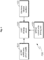
- Fig. 1 is a block diagram illustrating a configuration of an electronic vibrator according to an embodiment of the present invention
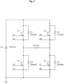
- Fig. 2 is a view illustrating a bridge circuit diagram of driving circuit of the oscillator shown in Fig. 1
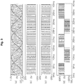
- Fig. 3 is a view illustrating waveforms applied to the driving circuit of the electronic vibrator shown in Fig. 1
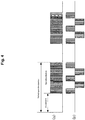
- Fig. 4 is a conceptual view illustrating pulsating operations to which the intermittent operation concept is applied in the electronic vibrator shown in Fig. 1
- Fig. 5 is a view illustrating an internal configuration of a vibration generator according to an embodiment of the present invention
- Fig. 6 is an exploded perspective view illustrating the vibration generator shown in Fig. 5
- Fig. 7 is a front view illustrating the vibration generator shown in Fig. 5 .
- the electronic vibrator 700 comprises a power source unit 500, a bridge circuit 300, a circuit driving unit 400, and a vibration generator 100.
- the power source unit 500 converts AC power into DC power.
- the power source unit 500 comprises a bridge diode and a smoothing capacitor.
- the bridge circuit 300 comprises an insulated-gate bipolar transistor (IGBT) as a power switching device in order to enable the drive of a large-capacity oscillator.
- IGBT insulated-gate bipolar transistor
- the bridge circuit 300 comprises a first transistor Z1 a first diode D1 connected in parallel with the first transistor Z1, a second transistor Z2 connected in series with the first transistor Z1, a second diode D2 connected in parallel with the second transistor Z2, a third transistor Z3 connected in parallel with the first transistor Z1, a third diode D3 connected in parallel with the third transistor Z3, a fourth transistor Z4 connected in series with the third transistor Z3, a fourth diode D4 connected in parallel with the fourth transistor Z4, a resistor RLoad connected as a start point between the first transistor Z1 and the second transistor Z2 and as an end point between the third transistor Z3 and the fourth transistor Z4, the power source unit Vin applying power to the first transistor Z1 and the second transistor Z2, and a ground unit 0 connected to the power source unit 500 and the second transistor Z2 and the fourth transistor Z4.
- the diode serves to prevent reverse noise in the bridge circuit 300.
- the circuit driving unit 400 drives the bridge circuit 300.
- a method is adopted to apply a sine wave which is a sine wave PWM modulation reference wave as well as a triangular wave.
- the triangular wave applied in the circuit driving unit 300 may be a triangular wave applied using an OP amplifier or a triangular wave applied using a program.
- the vibration generator 100 comprises an E core 10, an I core 20, a winding unit 30, a housing 40, a wing plate 50, a bottom-plate 60, a bolt 70, and a urethane spring 80.
- the E core 10 has an E-shape, is made of a steel plate, and comprises stacked layers.
- the I core 20 is positioned to be spaced apart from the E core 10, is made of a steel plate, comprises stacked layers, and have an I-shape.
- the winding unit 30 is wound around a portion horizontally protruding from the center of the E core 10. AC current is applied to the winding unit 30.
- the current supplied from the bridge circuit 300 is provided to the winding unit 30.
- the housing 40 contains the E core 10, the I core 20, and the winding unit 30.
- the wing plate 50 protrudes from a side wall of the housing 40 and comprises a wing through-hole 52 which is a bored hole.
- the bottom plate 60 is positioned to be spaced apart from the housing 40 and has a containing groove 62 to contain the I core 20.
- the bolt 70 penetrates the wing through-hole 50 to couple with the bottom plate 60.
- the urethane spring 80 is coupled with the housing 40 to adjust an impact and buffering.
- the urethane spring is made of urethane.
- the urethane spring 80 comprise an upper spring 82 and a lower spring 84.
- the upper spring 82 is positioned between a head of the bolt 70 and an upper surface of the wing plate 50.
- the lower spring 82 is positioned between a lower surface of the wing plate 50 and the bottom plate 60.
- the E core 10 is preferably made of a silicon steel plate to generate a strong electromagnetic force.
- the electromagnetic vibrator 200 having the configuration as described above is used as follows.
- the waveforms applied to the circuit driving unit 300 are as follows.
- the waveforms of two sine waves which are modulation reference waves shown in Fig. 3a are compared with the waveforms of the triangular wave which has a carrier waveform.
- a modulated waveform having a (+) polarity is generated.
- the triangular wave is larger, a modulated waveform having a (-) polarity is generated.
- the PWM modulated waveform of the preceding sine wave and the triangular wave is as shown in Fig. 3 (b)
- the PWM modulated waveform of the back sine wave and the triangular wave is as shown in Fig. 3(c) .
- the advantage of such scheme is to address the issue of current increase due to the increased conduction time of the power device in a very low frequency operation region of 40 Hz or less.
- the operation method shown in Fig. 3 enables a smooth load operation.
- the operation waveform of Fig. 3(c) is changed to have an idle period and an operation period as illustrated in Fig. 4(a) to apply energy to the vibration generator 100 so that a required amount of impact may be obtained.
- the current having the waveform as described above is applied to the winding unit 30.
- the housing 40 is vibrated to repeatedly move toward and away from the bottom plate member 60.
- Such vibration is amplified or relaxed by the upper spring 82 and the lower spring 84 to generate a constant vibration.
- the E core 10 is made of a silicon steel plate to generate strong electromagnetic force.
- the I core 20 having an alphabet I shape is used to prevent electromagnetic induction phenomenon (eddy current phenomenon) caused by such strong electromagnetic force.
Landscapes
- Engineering & Computer Science (AREA)
- Mechanical Engineering (AREA)
- Physics & Mathematics (AREA)
- Electromagnetism (AREA)
- Power Engineering (AREA)
- Apparatuses For Generation Of Mechanical Vibrations (AREA)
- Inverter Devices (AREA)
Applications Claiming Priority (2)
| Application Number | Priority Date | Filing Date | Title |
|---|---|---|---|
| KR1020140149518A KR101523352B1 (ko) | 2014-10-29 | 2014-10-29 | 전자 바이브레이터 |
| PCT/KR2015/010795 WO2016068520A2 (fr) | 2014-10-29 | 2015-10-13 | Vibreur électronique |
Publications (2)
| Publication Number | Publication Date |
|---|---|
| EP3214761A2 true EP3214761A2 (fr) | 2017-09-06 |
| EP3214761A4 EP3214761A4 (fr) | 2018-07-18 |
Family
ID=53395615
Family Applications (1)
| Application Number | Title | Priority Date | Filing Date |
|---|---|---|---|
| EP15854181.3A Withdrawn EP3214761A4 (fr) | 2014-10-29 | 2015-10-13 | Vibreur électronique |
Country Status (4)
| Country | Link |
|---|---|
| US (1) | US10413939B2 (fr) |
| EP (1) | EP3214761A4 (fr) |
| KR (1) | KR101523352B1 (fr) |
| WO (1) | WO2016068520A2 (fr) |
Families Citing this family (6)
| Publication number | Priority date | Publication date | Assignee | Title |
|---|---|---|---|---|
| US10218320B1 (en) * | 2017-08-31 | 2019-02-26 | Echowell Electronics Co., Ltd. | Vacuum tube audio amplifier |
| KR101964558B1 (ko) | 2018-07-20 | 2019-04-03 | 박춘복 | 스케일 제거 전자 해머장치 |
| KR102014073B1 (ko) | 2018-11-09 | 2019-08-26 | 파스코이엔지(주) | 전자 바이브레이터 |
| WO2021134540A1 (fr) * | 2019-12-31 | 2021-07-08 | 西门子股份公司 | Disjoncteur hybride, système de disjoncteur hybride, et procédé de disjonction |
| KR102187573B1 (ko) * | 2020-06-19 | 2020-12-07 | 임현윤 | 전자 해머 |
| KR102444182B1 (ko) * | 2020-09-07 | 2022-09-16 | 파스코이엔지(주) | 정현파 듀티 변조를 적용한 전자 바이브레이터 구동 알고리즘 |
Family Cites Families (13)
| Publication number | Priority date | Publication date | Assignee | Title |
|---|---|---|---|---|
| JPH0263581A (ja) * | 1988-08-30 | 1990-03-02 | Hiroshi Hirata | 電磁バイブレータ |
| JPH0591746A (ja) | 1991-09-27 | 1993-04-09 | Toshiba Corp | Pwm交流電力制御装置 |
| US6388417B1 (en) * | 1999-12-06 | 2002-05-14 | Macrosonix Corporation | High stability dynamic force motor |
| JP2002095079A (ja) * | 2000-09-12 | 2002-03-29 | Citizen Electronics Co Ltd | 多機能型音響装置 |
| JP2002192073A (ja) * | 2000-12-22 | 2002-07-10 | Mitsubishi Materials Corp | 振動発生器 |
| WO2004064084A2 (fr) * | 2003-01-03 | 2004-07-29 | Nucore, Inc. | Inducteur auto-amorti |
| KR20040089162A (ko) | 2003-04-10 | 2004-10-21 | 주식회사 인벤트로닉스 | 공진 주파수 분배기능을 갖는 초음파 발생장치 |
| EP1568420B1 (fr) * | 2004-02-29 | 2018-08-15 | BOMAG GmbH | Dispositif et méthode de commande pour une machine vibrante |
| DE102004010846A1 (de) * | 2004-03-05 | 2005-09-22 | BSH Bosch und Siemens Hausgeräte GmbH | Vorrichtung zur Regelung des Ankerhubs in einem reversierenden Linearantrieb |
| KR101203927B1 (ko) | 2010-07-20 | 2012-11-22 | 안태준 | 고주파 및 저주파 진동 발생 시스템 |
| KR101803540B1 (ko) * | 2012-08-13 | 2017-11-30 | 페어차일드코리아반도체 주식회사 | 피에조 구동 회로 및 그 구동 방법 |
| KR20140064559A (ko) * | 2012-11-20 | 2014-05-28 | 강인승 | 분체 이송설비의 전자해머용 맥동파 구동장치 |
| DE102013219167B4 (de) * | 2013-04-26 | 2017-03-02 | Conti Temic Microelectronic Gmbh | Zwei Verfahren, Vorrichtung und Verwendung davon, jeweils zum Einschalten oder Abschalten eines elektronischen Bauelements |
-
2014
- 2014-10-29 KR KR1020140149518A patent/KR101523352B1/ko active Active
-
2015
- 2015-10-13 US US15/523,030 patent/US10413939B2/en active Active
- 2015-10-13 WO PCT/KR2015/010795 patent/WO2016068520A2/fr not_active Ceased
- 2015-10-13 EP EP15854181.3A patent/EP3214761A4/fr not_active Withdrawn
Also Published As
| Publication number | Publication date |
|---|---|
| WO2016068520A3 (fr) | 2017-04-27 |
| EP3214761A4 (fr) | 2018-07-18 |
| KR101523352B1 (ko) | 2015-05-28 |
| US10413939B2 (en) | 2019-09-17 |
| US20170312783A1 (en) | 2017-11-02 |
| WO2016068520A2 (fr) | 2016-05-06 |
Similar Documents
| Publication | Publication Date | Title |
|---|---|---|
| EP3214761A2 (fr) | Vibreur électronique | |
| JP4350784B1 (ja) | 振動装置の駆動制御装置及び駆動制御方法 | |
| CN101548402A (zh) | 用于控制可变负载的超声波换能器的功率驱动电路 | |
| AR195381A1 (es) | Dispositivo para regular la ener gia de corriente alterna suministrada a un transformador de alto voltaje que excita un precipitador electrico a traves de medios rectificadores | |
| US20170022762A1 (en) | System and method for cleaning of a drill bit | |
| CN209072344U (zh) | 用于谐振电源转换器的功率极限电路 | |
| KR101602172B1 (ko) | 자기장과 토네이도 와류 기술을 이용한 장거리 준설토 운송 시스템 및 그 제어방법 | |
| KR101528327B1 (ko) | 진동발생기 | |
| DE602005023855D1 (de) | Ultraschallreinigungsvorrichtung für bohrloch | |
| KR101964558B1 (ko) | 스케일 제거 전자 해머장치 | |
| CN201841139U (zh) | 长管道高效超声波防垢/除垢装置 | |
| KR101563316B1 (ko) | 분체 이송설비의 진동 장치 운전시스템 | |
| KR20140064559A (ko) | 분체 이송설비의 전자해머용 맥동파 구동장치 | |
| KR101531972B1 (ko) | 발진기 구동 회로 | |
| CN203781274U (zh) | 一种斗式提升机 | |
| KR102444182B1 (ko) | 정현파 듀티 변조를 적용한 전자 바이브레이터 구동 알고리즘 | |
| CN208171355U (zh) | 一种具有信号传输功能的超声波流量计 | |
| KR20190103663A (ko) | 압송 콘크리트 이송상태 평가 및 유지관리 시스템 | |
| KR20150106220A (ko) | 준설토 이송 배관 폐색 방지 장치 | |
| CN202140411U (zh) | 一种防卸螺栓头 | |
| CN206289934U (zh) | 振捣器 | |
| CN208906826U (zh) | 一种防止油泥粘结的斗式提升机料斗 | |
| CN209514332U (zh) | 一种用于物料运输的模块化结构控制系统 | |
| KR102187573B1 (ko) | 전자 해머 | |
| CN204471961U (zh) | 上胶机 |
Legal Events
| Date | Code | Title | Description |
|---|---|---|---|
| STAA | Information on the status of an ep patent application or granted ep patent |
Free format text: STATUS: THE INTERNATIONAL PUBLICATION HAS BEEN MADE |
|
| PUAI | Public reference made under article 153(3) epc to a published international application that has entered the european phase |
Free format text: ORIGINAL CODE: 0009012 |
|
| STAA | Information on the status of an ep patent application or granted ep patent |
Free format text: STATUS: THE APPLICATION HAS BEEN PUBLISHED |
|
| AK | Designated contracting states |
Kind code of ref document: A2 Designated state(s): AL AT BE BG CH CY CZ DE DK EE ES FI FR GB GR HR HU IE IS IT LI LT LU LV MC MK MT NL NO PL PT RO RS SE SI SK SM TR |
|
| AX | Request for extension of the european patent |
Extension state: BA ME |
|
| STAA | Information on the status of an ep patent application or granted ep patent |
Free format text: STATUS: REQUEST FOR EXAMINATION WAS MADE |
|
| 17P | Request for examination filed |
Effective date: 20171027 |
|
| RBV | Designated contracting states (corrected) |
Designated state(s): AL AT BE BG CH CY CZ DE DK EE ES FI FR GB GR HR HU IE IS IT LI LT LU LV MC MK MT NL NO PL PT RO RS SE SI SK SM TR |
|
| DAV | Request for validation of the european patent (deleted) | ||
| DAX | Request for extension of the european patent (deleted) | ||
| A4 | Supplementary search report drawn up and despatched |
Effective date: 20180620 |
|
| RIC1 | Information provided on ipc code assigned before grant |
Ipc: B02C 19/16 20060101ALI20180614BHEP Ipc: H03K 17/08 20060101AFI20180614BHEP Ipc: B06B 1/02 20060101ALI20180614BHEP Ipc: H02K 33/16 20060101ALI20180614BHEP Ipc: H03K 3/353 20060101ALI20180614BHEP Ipc: H03K 17/567 20060101ALI20180614BHEP Ipc: B06B 1/04 20060101ALI20180614BHEP |
|
| GRAP | Despatch of communication of intention to grant a patent |
Free format text: ORIGINAL CODE: EPIDOSNIGR1 |
|
| STAA | Information on the status of an ep patent application or granted ep patent |
Free format text: STATUS: GRANT OF PATENT IS INTENDED |
|
| INTG | Intention to grant announced |
Effective date: 20190710 |
|
| GRAS | Grant fee paid |
Free format text: ORIGINAL CODE: EPIDOSNIGR3 |
|
| STAA | Information on the status of an ep patent application or granted ep patent |
Free format text: STATUS: THE APPLICATION IS DEEMED TO BE WITHDRAWN |
|
| 18D | Application deemed to be withdrawn |
Effective date: 20191121 |