EP3214762B1 - Appareil d'entrée - Google Patents
Appareil d'entrée Download PDFInfo
- Publication number
- EP3214762B1 EP3214762B1 EP17157518.6A EP17157518A EP3214762B1 EP 3214762 B1 EP3214762 B1 EP 3214762B1 EP 17157518 A EP17157518 A EP 17157518A EP 3214762 B1 EP3214762 B1 EP 3214762B1
- Authority
- EP
- European Patent Office
- Prior art keywords
- operation knob
- coil spring
- spring support
- electrostatic
- compression
- Prior art date
- Legal status (The legal status is an assumption and is not a legal conclusion. Google has not performed a legal analysis and makes no representation as to the accuracy of the status listed.)
- Active
Links
Images


Classifications
-
- H—ELECTRICITY
- H03—ELECTRONIC CIRCUITRY
- H03K—PULSE TECHNIQUE
- H03K17/00—Electronic switching or gating, i.e. not by contact-making and –breaking
- H03K17/94—Electronic switching or gating, i.e. not by contact-making and –breaking characterised by the way in which the control signals are generated
- H03K17/945—Proximity switches
- H03K17/955—Proximity switches using a capacitive detector
-
- H—ELECTRICITY
- H03—ELECTRONIC CIRCUITRY
- H03K—PULSE TECHNIQUE
- H03K17/00—Electronic switching or gating, i.e. not by contact-making and –breaking
- H03K17/94—Electronic switching or gating, i.e. not by contact-making and –breaking characterised by the way in which the control signals are generated
- H03K17/96—Touch switches
- H03K17/962—Capacitive touch switches
-
- H—ELECTRICITY
- H01—ELECTRIC ELEMENTS
- H01H—ELECTRIC SWITCHES; RELAYS; SELECTORS; EMERGENCY PROTECTIVE DEVICES
- H01H3/00—Mechanisms for operating contacts
- H01H3/02—Operating parts, i.e. for operating driving mechanism by a mechanical force external to the switch
- H01H2003/0293—Operating parts, i.e. for operating driving mechanism by a mechanical force external to the switch with an integrated touch switch
-
- H—ELECTRICITY
- H01—ELECTRIC ELEMENTS
- H01H—ELECTRIC SWITCHES; RELAYS; SELECTORS; EMERGENCY PROTECTIVE DEVICES
- H01H2239/00—Miscellaneous
- H01H2239/006—Containing a capacitive switch or usable as such
-
- H—ELECTRICITY
- H01—ELECTRIC ELEMENTS
- H01H—ELECTRIC SWITCHES; RELAYS; SELECTORS; EMERGENCY PROTECTIVE DEVICES
- H01H25/00—Switches with compound movement of handle or other operating part
- H01H25/04—Operating part movable angularly in more than one plane, e.g. joystick
- H01H25/041—Operating part movable angularly in more than one plane, e.g. joystick having a generally flat operating member depressible at different locations to operate different controls
-
- H—ELECTRICITY
- H01—ELECTRIC ELEMENTS
- H01H—ELECTRIC SWITCHES; RELAYS; SELECTORS; EMERGENCY PROTECTIVE DEVICES
- H01H3/00—Mechanisms for operating contacts
- H01H3/02—Operating parts, i.e. for operating driving mechanism by a mechanical force external to the switch
- H01H3/0213—Combined operation of electric switch and variable impedance, e.g. resistor, capacitor
-
- H—ELECTRICITY
- H03—ELECTRONIC CIRCUITRY
- H03K—PULSE TECHNIQUE
- H03K2217/00—Indexing scheme related to electronic switching or gating, i.e. not by contact-making or -breaking covered by H03K17/00
- H03K2217/94—Indexing scheme related to electronic switching or gating, i.e. not by contact-making or -breaking covered by H03K17/00 characterised by the way in which the control signal is generated
- H03K2217/96—Touch switches
- H03K2217/96054—Double function: touch detection combined with detection of a movable element
-
- H—ELECTRICITY
- H03—ELECTRONIC CIRCUITRY
- H03K—PULSE TECHNIQUE
- H03K2217/00—Indexing scheme related to electronic switching or gating, i.e. not by contact-making or -breaking covered by H03K17/00
- H03K2217/94—Indexing scheme related to electronic switching or gating, i.e. not by contact-making or -breaking covered by H03K17/00 characterised by the way in which the control signal is generated
- H03K2217/96—Touch switches
- H03K2217/9607—Capacitive touch switches
- H03K2217/960755—Constructional details of capacitive touch and proximity switches
- H03K2217/96076—Constructional details of capacitive touch and proximity switches with spring electrode
Definitions
- the present invention relates to an input apparatus including a switch that switches an input mode as a result of an operation knob being operated and an electrostatic capacitance sensor that detects an operating body, such as a finger, coming close to or being in contact with the operation knob.
- an input apparatus disclosed in Japanese Unexamined Patent Application Publication No. 2015-15202 is known as an example of an input apparatus that includes an electrostatic capacitance sensor.
- the electrostatic capacitance sensor is incorporated in an operation knob and detects a finger or the like coming close to or being in contact with the operation knob.
- the electrostatic capacitance sensor has a structure in which detected information is retrieved by using a flexible printed circuit board.
- the input apparatus disclosed in Japanese Unexamined Patent Application Publication No. 2015-15202 uses a flexible printed circuit board in order to retrieve detected information obtained by the electrostatic capacitance sensor, and this results in an increase in the manufacturing costs of components.
- US 2007/052598 A1 discloses a presence detection control knob.
- the control knob comprises a mobile part capable of being actuated manually and linked with an electromechanical transducer.
- the knob also comprises a metal surface arranged in the vicinity of the mobile part and means to measure the capacitance of the metal surface so that the presence of a finger in the vicinity of the mobile part can be detected.
- US 2011/042196 A1 discloses a push switch equipped with a capacitance sensor and an input apparatus including the same, the input apparatus being in accordance with the preamble of claim 1.
- the push switch includes an operating member, a holding member, a detecting electrode including a plate-shaped spring, a conductive coil spring, and a wiring substrate.
- the operating member includes a top portion.
- the rear surface of the top portion and the holding member define a storage space.
- the detecting electrode received in the storage space, includes a detecting portion in resilient contact with the top portion, a base in resilient contact with the coil spring, and a height adjusting portion coupling the detecting portion to the base. The amount of compression of the detecting electrode is defined depending on the height of the storage space.
- the present invention relates to an input apparatus in accordance with the appended claims.
- the present invention provides an input apparatus capable of reducing the manufacturing costs of components and having a favorable assembling ability.
- the present invention provides an input apparatus capable of suppressing rattling of an operation knob with respect to a case and ensuring stable operation of the operation knob.
- An input apparatus includes a switch that switches an input mode as a result of an operation knob, which is attached to a case, being operated and an electrostatic capacitance sensor that detects an operating body coming close to or being in contact with the operation knob.
- the electrostatic capacitance sensor includes an electrostatic-capacitance detection plate attached to a rear surface of the operation knob, the electrostatic-capacitance detection plate being made of a metal, a circuit board disposed in such a manner as to face the operation knob with a predetermined distance between the circuit board and the operation knob, an electrostatic capacitance detection circuit pattern formed on the circuit board, and a compression-coil spring having a first end, which is caused to abut against the electrostatic-capacitance detection plate by an urging force in such a manner as to be electrically connected to the electrostatic-capacitance detection plate, and a second end, which is caused to abut against the electrostatic capacitance detection circuit pattern by an urging force so as to be electrically connected to the electrostatic capacitance
- the electrostatic-capacitance detection plate and the electrostatic capacitance detection circuit pattern may be electrically connected to each other.
- a spring support member is provided on a side on which the rear surface of the operation knob is present.
- a spring support hole into which the compression-coil spring is inserted is formed in the spring support member in such a manner as to extend through the spring support member.
- the spring support hole is formed such that a width of the spring support hole on an entry side from which the compression-coil spring is inserted is large, and the width of the spring support hole on an exit side from which the compression-coil spring is exited is small. A portion of the compression-coil spring on the first end side is supported in such a manner as to be capable of freely reciprocating on the exit side of the spring support hole.
- the width of the spring support hole on the exit side, on which the portion of the compression-coil spring on the first end side is supported is small, positioning of the portion of the compression-coil spring on the first end side in a radial direction is performed with certainty, and the portion of the compression-coil spring on the first end side is stably supported in the spring support hole.
- the spring support hole of the spring support member is tapered such that the width of the spring support hole gradually decreases from the entry side, from which the compression-coil spring is inserted, toward the exit side, from which the compression-coil spring is exited.
- the compression-coil spring may be linearly supported. Therefore, the first end of the compression-coil spring may be made to constantly abut against the electrostatic capacitance detection plate by an urging force, and the contact state between the first end of the compression-coil spring and the electrostatic capacitance detection plate may be stable.
- the compression-coil spring on the first end side which is supported by the spring support member, is closely wound, the compression-coil spring may be easily supported, and a stably supported state of the compression-coil spring may be obtained.
- the portion of the compression-coil spring on the first end side is closely wound, when transporting the compression-coil springs, the compression-coil springs are less likely to become tangled with one another, and an operation of picking up the compression-coil springs may be easily performed.
- the switch is a four-direction push switch attached to the case such that the operation knob is capable of being freely inclined in four directions, which are perpendicular to one another, and the first end of the compression-coil spring is supported by the spring support member in such a manner as to be caused to abut against the electrostatic-capacitance detection plate by an urging force and to be located at the center of inclination of the operation knob.
- an input apparatus capable of reducing the manufacturing costs of components and having a favorable assembling ability can be provided.
- an input apparatus capable of suppressing rattling of an operation knob with respect to a case and ensuring stable operation of the operation knob can be provided.
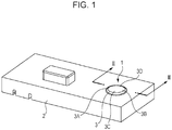
- Fig. 1 is a perspective view of an input apparatus according to the present embodiment of the present invention.
- Fig. 2 is an enlarged cross-sectional view taken along line II-II of Fig. 1 schematically illustrating the input apparatus.
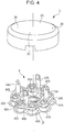
- Fig. 3 is an exploded perspective view of the input apparatus.
- Fig. 4 is an enlarged, exploded perspective view illustrating a four-direction push switch of the input apparatus.
- Fig. 5 is an enlarged perspective view illustrating the internal structure of an operation knob of the input apparatus.
- Fig. 6 is an enlarged perspective view of a spring support member of the input apparatus.
- Fig. 7 is an enlarged perspective view of a portion of a case of the input apparatus on which the operation knob is to be mounted.
- Fig. 8 is an enlarged perspective view of an electrostatic-capacitance detection plate of the input apparatus.
- Fig. 9 is an enlarged cross-sectional view illustrating a portion of the input apparatus including the spring support member illustrated in Fig. 2 .
- An input apparatus 1 includes a four-direction push switch 4 serving as a switch that switches an input mode as a result of an operation knob 3, which is mounted on a case 2, being operated and an electrostatic capacitance sensor 5 that detects an operating body, such as a finger, coming close to or being in contact with the operation knob 3.
- the four-direction push switch 4 is a switch capable of switching input modes each corresponding to one of four directions, which are perpendicular to one another, as a result of the operation knob 3 being press-operated so as to be inclined in one of the four directions.
- the four-direction push switch 4 includes a first push switch portion 40, a second push switch portion 41, a third push switch portion 42, and a fourth push switch portion 43 that are mounted on a circuit board 6, which is disposed on a lower base 2a of the case 2, in such a manner as to be spaced apart from one another by 90 degrees.
- the four-direction push switch 4 further includes a first stem portion 44, a second stem portion 45, a third stem portion 46, and a fourth stem portion 47 each of which performs a pressing operation on a corresponding one of the push switch portions 40, 41, 42, and 43 as a result of the operation knob 3 being press-operated so as to be inclined.
- the operation knob 3 is formed in a cylindrical shape having a small height.
- a first pressing portion 3A is formed in the top surface of the operation knob 3 and is used for driving the first push switch portion 40 by operating the operation knob 3 such that the operation knob 3 is inclined.
- a second pressing portion 3B is formed in the top surface of the operation knob 3 and is used for driving the second push switch portion 41 by operating the operation knob 3 such that the operation knob 3 is inclined.
- a third pressing portion 3C is formed in the top surface of the operation knob 3 and is used for driving the third push switch portion 42 by operating the operation knob 3 such that the operation knob 3 is inclined.
- a fourth pressing portion 3D is formed in the top surface of the operation knob 3 and is used for driving the fourth push switch portion 43 by operating the operation knob 3 such that the operation knob 3 is inclined.
- the first push switch portion 40 includes a pair of first rubber switch portions 40A and 40A each of which is formed on a portion of a protective cover 2b, which is disposed on the circuit board 6.
- the second push switch portion 41 includes a pair of second rubber switch portions 41A and 41A each of which is formed on a portion of the protective cover 2b.
- the third push switch portion 42 includes a pair of third rubber switch portions 42A and 42A each of which is formed on a portion of the protective cover 2b.
- the fourth push switch portion 43 includes a pair of fourth rubber switch portions 43A and 43A each of which is formed on a portion of the protective cover 2b.
- Each of the first rubber switch portions 40A is formed in a dome-like shape in such a manner as to elastically deform when a pressing operation is performed on the first pressing portion 3A of the operation knob 3.
- a moving contact (not illustrated) is provided on the inner top surface of a main body of the first rubber switch portion 40A, which is formed in a dome-like shape.
- the main body of the first rubber switch portion 40A which is formed in a dome-like shape, is recessed as a result of receiving a pressing force from the operation knob 3, and the moving contact is brought into contact with a stationary contact, which is provided on the circuit board 6.
- the first rubber switch portion 40A is brought into an ON state.
- the main body of the first rubber switch portion 40A When application of a pressing force to the first pressing portion 3A is stopped, the main body of the first rubber switch portion 40A returns to its original dome-like shape by using its elastic energy, and the moving contact is separated from the stationary contact. As a result, the first rubber switch portion 40A is brought into an OFF state.
- Each of the second rubber switch portions 41A is formed in a dome-like shape in such a manner as to elastically deform when a pressing operation is performed on the second pressing portion 3B of the operation knob 3.
- a moving contact (not illustrated) is provided on the inner top surface of a main body of the second rubber switch portion 41A, which is formed in a dome-like shape.
- the main body of the second rubber switch portion 41A which is formed in a dome-like shape, is recessed as a result of receiving a pressing force from the operation knob 3, and the moving contact is brought into contact with a stationary contact, which is provided on the circuit board 6.
- the second rubber switch portion 41A is brought into the ON state.
- Each of the third rubber switch portions 42A is formed in a dome-like shape in such a manner as to elastically deform when a pressing operation is performed on the third pressing portion 3C of the operation knob 3.
- a moving contact (not illustrated) is provided on the inner top surface of a main body of the third rubber switch portion 42A, which is formed in a dome-like shape.
- the main body of the third rubber switch portion 42A which is formed in a dome-like shape, is recessed as a result of receiving a pressing force from the operation knob 3, and the moving contact is brought into contact with a stationary contact, which is provided on the circuit board 6.
- the third rubber switch portion 42A is brought into the ON state.
- the main body of the third rubber switch portion 42A When application of a pressing force to the third pressing portion 3C is stopped, the main body of the third rubber switch portion 42A returns to its original dome-like shape by using its elastic energy, and the moving contact is separated from the stationary contact. As a result, the third rubber switch portion 42A is brought into the OFF state.
- Each of the fourth rubber switch portions 43A is formed in a dome-like shape in such a manner as to elastically deform when a pressing operation is performed on the fourth pressing portion 3D of the operation knob 3.
- a moving contact (not illustrated) is provided on the inner top surface of a main body of the fourth rubber switch portion 43A, which is formed in a dome-like shape.
- the main body of the fourth rubber switch portion 43A which is formed in a dome-like shape, is recessed as a result of receiving a pressing force from the operation knob 3, and the moving contact is brought into contact with a stationary contact, which is provided on the circuit board 6.
- the fourth rubber switch portion 43A is brought into the ON state.
- the main body of the fourth rubber switch portion 43A When application of a pressing force to the fourth pressing portion 3D is stopped, the main body of the fourth rubber switch portion 43A returns to its original dome-like shape by using its elastic energy, and the moving contact is separated from the stationary contact. As a result, the fourth rubber switch portion 43A is brought into the OFF state.
- the first stem portion 44 includes a stem main body 44A and a first pressing piece portion 44B, which is formed on the lower end of the stem main body 44A and which is used for pressing the pair of first rubber switch portions 40A and 40A, and is substantially T-shaped.
- the stem main body 44A is supported by a stem support hole 2A, which is formed in such a manner as to extend through a bottom portion of an operation-knob accommodating portion 20 (described later), so as to be capable of freely reciprocating in the vertical direction with respect to the circuit board 6.
- the second stem portion 45 includes a stem main body 45A and a second pressing piece portion 45B, which is formed on the lower end of the stem main body 45A and which is used for pressing the pair of second rubber switch portions 41A and 41A, and is substantially T-shaped.
- the stem main body 45A is supported by another stem support hole 2A, which is formed in such a manner as to extend through the bottom portion of the operation-knob accommodating portion 20, so as to be capable of freely reciprocating in the vertical direction with respect to the circuit board 6.
- the third stem portion 46 includes a stem main body 46A and a third pressing piece portion 46B, which is formed on the lower end of the stem main body 46A and which is used for pressing the pair of third rubber switch portions 42A and 42A, and is substantially T-shaped.
- the stem main body 46A is supported by another stem support hole 2A, which is formed in such a manner as to extend through the bottom portion of the operation-knob accommodating portion 20, so as to be capable of freely reciprocating in the vertical direction with respect to the circuit board 6.
- the fourth stem portion 47 includes a stem main body 47A and a fourth pressing piece portion 47B, which is formed on the lower end of the stem main body 47A and which is used for pressing the pair of fourth rubber switch portions 43A and 43A, and is substantially T-shaped.
- the stem main body 47A is supported by another stem support hole 2A, which is formed in such a manner as to extend through the bottom portion of the operation-knob accommodating portion 20, so as to be capable of freely reciprocating in the vertical direction with respect to the circuit board 6.
- a first pressing projection piece 3E is formed on the rear surface of the operation knob 3 in such a manner as to vertically extend therefrom and presses the stem main body 44A of the first stem portion 44 in a direction toward the circuit board 6 by being brought into contact with an end of the stem main body 44A.
- the end of the stem main body 44A is tapered, and when the operation knob 3 is operated so as to be inclined, the first pressing projection piece 3E of the operation knob 3 is smoothly brought into contact with the end of the stem main body 44A, so that the operation knob 3 can be smoothly operated.
- a second pressing projection piece 3F is formed on the rear surface of the operation knob 3 in such a manner as to vertically extend therefrom and presses the stem main body 45A of the second stem portion 45 in the direction toward the circuit board 6 by being brought into contact with an end of the stem main body 45A.
- the end of the stem main body 45A is tapered, and when the operation knob 3 is operated so as to be inclined, the second pressing projection piece 3F of the operation knob 3 is smoothly brought into contact with the end of the stem main body 45A, so that the operation knob 3 can be smoothly operated.
- a third pressing projection piece 3G is formed on the rear surface of the operation knob 3 in such a manner as to vertically extend therefrom and presses the stem main body 46A of the third stem portion 46 in the direction toward the circuit board 6 by being brought into contact with an end of the stem main body 46A.
- the end of the stem main body 46A is tapered, and when the operation knob 3 is operated so as to be inclined, the third pressing projection piece 3G of the operation knob 3 is smoothly brought into contact with the end of the stem main body 46A, so that the operation knob 3 can be smoothly operated.
- a fourth pressing projection piece 3H is formed on the rear surface of the operation knob 3 in such a manner as to vertically extend therefrom and presses the stem main body 47A of the fourth stem portion 47 in the direction toward the circuit board 6 by being brought into contact with an end of the stem main body 47A.
- the end of the stem main body 47A is tapered, and when the operation knob 3 is operated so as to be inclined, the fourth pressing projection piece 3H of the operation knob 3 is smoothly brought into contact with the end of the stem main body 47A, so that the operation knob 3 can be smoothly operated.
- the four-direction push switch 4 can select and cause to operate one of the push switch portions 40, 41, 42, and 43 and can perform a switching operation between the input modes corresponding to the four directions.
- a spring support member 7 that supports a compression-coil spring 51 (hereinafter referred to as coil spring 51), which is included in the electrostatic capacitance sensor 5 (described later), is mounted on the rear surface of the operation knob 3.
- a pair of shaft portions 7A and 7A are each formed on one of two side portions of the spring support member 7, the two side portions opposing each other, in such a manner as to protrude therefrom.
- a pair of bearing pieces 31 and 31 each having elasticity are formed on the rear surface of the operation knob 3 in such a manner as to vertically extend therefrom and to face each other.
- the shaft portions 7A and 7A of the spring support member 7 are fitted into bearing holes 3J and 3J of the bearing pieces 31 and 31.
- the shaft portions 7A and 7A of the spring support member 7 are fitted into bearing holes 3J and 3J of the bearing pieces 31 and 31, and the spring support member 7 is attached to the operation knob 3 so as to be capable of freely swinging around the shaft portions 7A and 7A.
- a top end portion of each of the shaft portions 7A and 7A of the spring support member 7 has an inclined surface 7B.
- An inner end portion of each of the bearing pieces 31 and 31 has an inclined surface 3K. Accordingly, when the shaft portions 7A and 7A of the spring support member 7 are fitted into the corresponding bearing holes 3J and 3J against an elastic force of the bearing pieces 31 and 31, the shaft portions 7A and 7A can be pressed while the inclined surfaces 7B, which are formed on the end portions of the shaft portions 7A and 7A, are moved along the corresponding inclined surfaces 3K of the bearing pieces 31 and 31, and the spring support member 7 can be smoothly attached to the operation knob 3.
- a pair of bearing holes 7C and 7C are formed in two side portions of the spring support member 7, the two side portions being perpendicular to the centers of swing of the pair of shaft portions 7A and 7A, so as to face each other. Note that the pair of bearing holes 7C and 7C are formed in such a manner as to extend through the spring support member 7.
- the operation knob 3 is incorporated in the circular operation-knob accommodating portion 20 that has an opening 2B, which is formed in an upper portion of the case 2.
- a pair of support pieces 2C and 2C are formed on the bottom portion of the operation-knob accommodating portion 20 in such a manner as to protrude therefrom and to face each other.
- a pair of shaft portions 2D and 2D are each formed on the inner side portion of a corresponding one of the pair of support pieces 2C and 2C in such a manner as as to protrude therefrom and to face each other.
- the shaft portions 2D and 2D are each fitted into a corresponding one of the bearing holes 7C and 7C of the spring support member 7, and the spring support member 7 is accommodated in the operation-knob accommodating portion 20 so as to be capable of freely swinging around the shaft portions 2D and 2D.
- the operation knob 3 is supported so as to be capable of being freely operated and inclined in two directions, and the operation knob 3 can selectively switch between a first input mode for pressing the first push switch portion 40 and a second input mode for pressing the second push switch portion 41.
- the operation knob 3 is supported so as to be capable of being freely operated and inclined in two directions, and the operation knob 3 can selectively switch between a third input mode for pressing the third push switch portion 42 and a four input mode for pressing the fourth push switch portion 43.
- the electrostatic capacitance sensor 5 includes an electrostatic-capacitance detection plate 50, which is provided on the rear surface of the operation knob 3 and which is made of a metal, an electrostatic capacitance detection circuit pattern 6A, which is formed on the circuit board 6, and the coil spring 51 having an upper end 51A, which is one of the two ends of the coil spring 51 and which is connected to the electrostatic-capacitance detection plate 50, and a lower end 51B, which is the other of the two ends of the coil spring 51 and which is electrically connected to electrostatic capacitance detection circuit pattern 6A.
- the electrostatic capacitance formed between the operating body and the electrostatic-capacitance detection plate 50 changes.
- the change in the electrostatic capacitance can be detected by an electrostatic capacitance detection circuit (not illustrated), which is provided on the circuit board 6, via the coil spring 51, and thus, the operating body, such as a finger, coming close to or being in contact with the operation knob 3 is detected.
- cutout portions 50A, 50A, 50A, and 50A are formed in an outer peripheral portion of the electrostatic-capacitance detection plate 50 in such a manner as to be spaced apart from one another by 90 degrees in the circumferential direction of the electrostatic-capacitance detection plate 50 (see Fig. 5 ).
- the electrostatic-capacitance detection plate 50 is positioned and fixed onto the rear surface of the operation knob 3.
- a portion of the coil spring 51 on the side of the upper end 51A is supported by the spring support member 7, which is attached to the operation knob 3.
- a spring support hole 7D is formed in the spring support member 7 in such a manner as to extend therethrough in the vertical direction.
- a lower opening 7a is formed at the lower end of the spring support hole 7D, and an upper opening 7b is formed at the upper end of the spring support hole 7D.
- the portion of the coil spring 51 on the side of the upper end 51A is supported in the upper opening 7b of the spring support hole 7D so as to be capable of freely reciprocating.
- the coil spring 51 is inserted into the spring support hole 7D through the lower opening 7a such that the upper end 51A projects to the outside from the upper opening 7b.
- the upper end 51A is caused to abut against a plate surface of the electrostatic-capacitance detection plate 50 by an urging force so as to be electrically connected to the electrostatic-capacitance detection plate 50
- the lower end 51B is caused to abut against the electrostatic capacitance detection circuit pattern 6A of the circuit board 6 by an urging force so as to be electrically connected to electrostatic capacitance detection circuit pattern 6A.
- the coil spring 51 is inserted into a spring support hole 2E, which is formed in a center portion of a bottom portion of the operation-knob accommodating portion 20 in such a manner as to extend through the bottom portion, and an intermediate portion 51C of the coil spring 51 is supported by the spring support hole 2E.
- a portion of the coil spring 51 on the side of the lower end 51B is inserted into a support hole 2F, which is formed in the protective cover 2b, so as to be supported by the support hole 2F.
- the electrostatic-capacitance detection plate 50 and electrostatic capacitance detection circuit pattern 6A can be electrically connected to each other. Therefore, it is not necessary to use a flexible printed circuit board, which leads to high manufacturing costs of components, as in the related art, and the electrostatic capacitance sensor 5 can be easily assembled.
- the upper end 51A of the coil spring 51 is caused to abut against a center portion 50a of the electrostatic-capacitance detection plate 50 by an urging force, and the center portion 50a corresponds to the center of inclination of the operation knob 3 in the four directions.
- the upper end 51A of the coil spring 51 is caused to abut against the center portion 50a of the electrostatic-capacitance detection plate 50 by an urging force, and when operating the operation knob 3 such that the operation knob 3 is inclined, a force is uniformly transferred to the operating body, such as a finger, and the operation knob 3 can be smoothly operated so as to be inclined in any one of the four directions.
- the operation knob 3 when the operation knob 3 is operated so as to be inclined, the upper end 51A of the coil spring 51 can smoothly slide on the plate surface of the capacitance detection plate 50 by using the urging force of the coil spring 51, and the electrical contact state between the upper end 51A of the coil spring 51 and the capacitance detection plate 50 can be constantly stable.
- the lower opening 7a is formed so as to have a width larger than that of the upper opening 7b, and the spring support hole 7D is tapered such that the width of the spring support hole 7D gradually decreases from the lower opening 7a toward the upper opening 7b.
- the upper opening 7b of the spring support hole 7D of the spring support member 7 has a small width, positioning of the upper end 51A of the coil spring 51 in a radial direction is performed with certainty, and the portion of the coil spring 51 on the side of the upper end 51A is stably supported in the spring support hole 7D.
- the portion of the coil spring 51 on the side of the upper end 51A and the portion of the coil spring 51 on the side of the lower end 51B are closely wound, and the intermediate portion 51C is sparsely wound. Since the portion of the coil spring 51 on the side of the upper end 51A, which is supported by the spring support member 7, is closely wound, the coil spring 51 can be easily supported, and a stably supported state of the coil spring 51 can be obtained. In addition, since the portion of the coil spring 51 on the side of the upper end 51A and the portion of the coil spring 51 on the side of the lower end 51B are closely wound, when transporting the coil springs 51, the coil springs 51 are less likely to become tangled with one another, and an operation of picking up the coil springs 51 may be easily performed.
- the operation knob 3 is inclined while the shaft portions 2D and 2D, which support the spring support member 7 such that the spring support member 7 is capable to freely swinging in the operation-knob accommodating portion 20, serve as the center of inclination of the operation knob 3.
- the second pressing projection piece 3F which is formed on the operation knob 3 in such a manner as to vertically extend therefrom, presses down the stem main body 45A of the second stem portion 45, and the second pressing piece portion 45B presses the pair of second rubber switch portions 41A and 41A.
- the main body of the second rubber switch portions 41A which is formed in a dome-like shape, is recessed, and the moving contact is brought into contact with the stationary contact, which is provided on the circuit board 6. As a result, the second rubber switch portions 41A is brought into the ON state.
- the first pressing projection piece 3E which is formed on the rear surface of the operation knob 3 in such a manner as to vertically extend therefrom, is separated from the end of the stem main body 44A of the first stem portion 44.
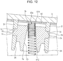
- the spring support member 7 swings together with the operation knob 3 around the shaft portions 2D and 2D as illustrated in Fig. 12 .
- the spring support hole 7D is tapered, the coil spring 51 is inclined, while the portion of the coil spring 51 on the side of the upper end 51A is supported in the upper opening 7b of the spring support hole 7D, to a position where the inner peripheral surface of the spring support hole 7D is in contact with the outer peripheral surface of the coil spring 51.
- the coil spring 51 can be maintained in a state of being linearly supported, and the contact state between the upper end 51A of the coil spring 51 and the capacitance detection plate 50 may be stable.
- the coil spring 51 is pressed down against the urging force thereof as a result of the operation knob 3 being operated so as to be inclined.
- the portion of the coil spring 51 on the side of the upper end 51A is supported in the upper opening 7b of the spring support hole 7D of the spring support member 7 so as to be capable of freely reciprocating, the contact state between the upper end 51A of the coil spring 51 and the capacitance detection plate 50 can be maintained.
- the operation knob 3 is inclined while the shaft portions 7A and 7A of the spring support member 7, which support the operation knob 3 such that the operation knob 3 is capable of freely swinging, serve as the center of inclination of the operation knob 3.
- the third pressing projection piece 3G which is formed on the operation knob 3 in such a manner as to vertically extend therefrom, presses down the stem main body 46A of the third stem portion 46, and the third pressing piece portion 46B presses the pair of third rubber switch portions 42A and 42A.
- the main body of the third rubber switch portions 42A which is formed in a dome-like shape, is recessed, and the moving contact is brought into contact with the stationary contact, which is provided on the circuit board 6. As a result, the third rubber switch portions 42A is brought into the ON state.
- the fourth pressing projection piece 3H which is formed on the rear surface of the operation knob 3 in such a manner as to vertically extend therefrom, is separated from the end of the stem main body 47A of the fourth stem portion 47.
- the operation knob 3 when the operation knob 3 is operated so as to be inclined, the operation knob 3 swings around the shaft portions 7A and 7A, whereas the spring support member 7 does not swing.
- the coil spring 51 whose portion on the side of the upper end 51A is supported by the spring support member 7 can be maintained in a state of being linearly supported in the spring support hole 7D, and the contact state between the upper end 51A of the coil spring 51 and the capacitance detection plate 50 may be stable.
- the coil spring 51 is pressed down against the urging force thereof as a result of the operation knob 3 being operated so as to be inclined.
- the electrostatic-capacitance detection plate 50 and electrostatic capacitance detection circuit pattern 6A can be electrically connected to each other. Therefore, it is not necessary to use a flexible printed circuit board, which leads to high manufacturing costs of components, as in the related art, and the electrostatic capacitance sensor 5 can be easily assembled.
- the present invention is not limited to the above-described embodiment.
- those skilled in the art may make various changes and alternations to the components according to the above-described embodiment and may perform combinations and sub-combinations of the components according to the above-described embodiment within the technical scope of the present invention or within a range equivalent to the technical scope of the present invention.
- the four-direction push switch 4 is used as a switch that switches the input modes
- the present invention is not limited to the four-direction push switch 4 and can be applied to a slide switch, a rotary switch, and the like each of which is provided with a function of switching an input mode.
- the portion of the coil spring 51 on the side of the upper end 51A and the portion of the coil spring 51 on the side of the lower end 51B are closely wound, and the intermediate portion 51C is sparsely wound.
- at least one of the two end portions of the coil spring 51, which is held by the spring support member 7, may be closely wound.
- the present invention can be applied to an input apparatus provided with an electrostatic capacitance sensor.
Landscapes
- Switches With Compound Operations (AREA)
Claims (4)
- Appareil d'entrée (1) comprenant :un commutateur (4) qui enclenche un mode d'entrée suite à l'actionnement d'un bouton de commande (3), qui est fixé à un boîtier (2) ; etun capteur de capacitance électrostatique (5) qui détecte un corps de commande se rapprochant ou étant en contact avec le bouton de commande,dans lequel le capteur de capacitance électrostatique comprendune plaque de détection de la capacitance électrostatique (50) fixée à la face arrière du bouton de commande, la plaque de détection de la capacitance électrostatique étant en métal,un circuit imprimé (6) disposé de manière à faire face au bouton de commande, la distance entre le circuit imprimé et le bouton de commande étant prédéterminée,un tracé de circuit de détection de la capacitance électrostatique (6A) formé sur le circuit imprimé, etun ressort hélicoïdal de compression (51) dont une première extrémité doit venir buter contre la plaque de détection de la capacitance électrostatique par l'action d'une force de sollicitation de manière à être connecté électriquement à la plaque de détection de la capacitance électrostatique, et dont une deuxième extrémité doit venir buter contre le tracé du circuit de détection de la capacitance électrostatique par l'action d'une force de sollicitation de manière à être connecté électriquement au tracé du circuit de détection de la capacitance électrostatique,dans lequelun élément de support du ressort (7) est situé sur un côté sur lequel se trouve la face arrière du bouton de commande,un orifice de support du ressort (7D), dans lequel le ressort hélicoïdal de compression est inséré, est formé dans l'élément de support du ressort de manière à s'étendre à travers l'élément de support du ressort,caractérisé en ce quel'orifice de support du ressort est formé de telle sorte qu'une largeur de l'orifice de support du ressort sur un côté entrée où le ressort hélicoïdal de compression est inséré est plus grande que la largeur de l'orifice de support du ressort sur un côté sortie par où le ressort hélicoïdal de compression sort,et en ce queune partie du ressort hélicoïdal de compression du côté de la première extrémité est supporté de manière à se déplacer librement en va-et-vient sur le côté sortie de l'orifice de support du ressort.
- L'appareil d'entrée selon la revendication 1,
dans lequel l'orifice de support du ressort est conique, de sorte que la largeur de l'orifice de support du ressort diminue graduellement depuis le côté entrée, par lequel le ressort hélicoïdal de compression est inséré, jusqu'au côté sortie, par où le ressort hélicoïdal de compression sort. - L'appareil d'entrée selon la revendication 1 ou 2,
dans lequel au moins une partie du ressort hélicoïdal de compression du côté de la première extrémité, qui est supportée par l'élément de support du ressort, est étroitement enroulée. - L'appareil d'entrée selon l'une quelconque des revendications 1 à 3,
dans lequel le commutateur est un bouton-poussoir à quatre directions fixé au boîtier de telle sorte que le bouton de commande peut être librement incliné dans quatre directions, qui sont perpendiculaires l'une par rapport à l'autre, et
dans lequel la première extrémité du ressort hélicoïdal de compression doit venir buter contre la plaque de détection de la capacitance électrostatique par l'action d'une force de sollicitation et est supportée par l'élément de support du ressort de manière à être située au centre d'inclinaison du bouton de commande.
Applications Claiming Priority (1)
| Application Number | Priority Date | Filing Date | Title |
|---|---|---|---|
| JP2016040965A JP6622628B2 (ja) | 2016-03-03 | 2016-03-03 | 入力装置 |
Publications (2)
| Publication Number | Publication Date |
|---|---|
| EP3214762A1 EP3214762A1 (fr) | 2017-09-06 |
| EP3214762B1 true EP3214762B1 (fr) | 2020-08-12 |
Family
ID=58158889
Family Applications (1)
| Application Number | Title | Priority Date | Filing Date |
|---|---|---|---|
| EP17157518.6A Active EP3214762B1 (fr) | 2016-03-03 | 2017-02-23 | Appareil d'entrée |
Country Status (2)
| Country | Link |
|---|---|
| EP (1) | EP3214762B1 (fr) |
| JP (1) | JP6622628B2 (fr) |
Families Citing this family (4)
| Publication number | Priority date | Publication date | Assignee | Title |
|---|---|---|---|---|
| JP2019114353A (ja) * | 2017-12-21 | 2019-07-11 | アルプスアルパイン株式会社 | 操作装置 |
| KR102010400B1 (ko) | 2018-06-20 | 2019-08-13 | 한국알프스 주식회사 | 다층기판 입력장치 |
| JP7428620B2 (ja) * | 2020-09-23 | 2024-02-06 | 株式会社東海理化電機製作所 | スイッチ装置 |
| JP2023121382A (ja) * | 2022-02-21 | 2023-08-31 | 株式会社東海理化電機製作所 | スイッチ装置、およびユーザインタフェース装置 |
Family Cites Families (5)
| Publication number | Priority date | Publication date | Assignee | Title |
|---|---|---|---|---|
| JP4317741B2 (ja) * | 2003-12-24 | 2009-08-19 | アルプス電気株式会社 | 4方向スイッチ装置 |
| FR2890488B1 (fr) * | 2005-09-02 | 2008-12-26 | Valeo Systemes Thermiques | Bouton de commande a detection de presence. |
| JP5292221B2 (ja) * | 2009-08-21 | 2013-09-18 | アルプス電気株式会社 | 静電容量センサ付きプッシュスイッチおよびそれを用いた入力装置 |
| DE102011087232A1 (de) * | 2011-09-01 | 2013-03-07 | Preh Gmbh | Schalter mit Schaltkappe und damit bewegbarer Elektrode |
| JP5936249B2 (ja) | 2013-07-08 | 2016-06-22 | アルプス電気株式会社 | 入力装置 |
-
2016
- 2016-03-03 JP JP2016040965A patent/JP6622628B2/ja active Active
-
2017
- 2017-02-23 EP EP17157518.6A patent/EP3214762B1/fr active Active
Non-Patent Citations (1)
| Title |
|---|
| None * |
Also Published As
| Publication number | Publication date |
|---|---|
| JP2017157462A (ja) | 2017-09-07 |
| JP6622628B2 (ja) | 2019-12-18 |
| EP3214762A1 (fr) | 2017-09-06 |
Similar Documents
| Publication | Publication Date | Title |
|---|---|---|
| EP3214762B1 (fr) | Appareil d'entrée | |
| US5613600A (en) | Rotatively-operated electronic component with push switch | |
| US7230197B2 (en) | Movable contact, moveable contact unit including the same, and switch including the same movable contact | |
| US8084699B2 (en) | Vehicle switch | |
| US11364435B2 (en) | Operation device | |
| US20220334608A1 (en) | Multidirectional input apparatus | |
| EP3611600B1 (fr) | Clavier | |
| JP4353964B2 (ja) | 複合操作型入力装置 | |
| EP3780052B1 (fr) | Dispositif de commutateur | |
| US20210082641A1 (en) | Switching device | |
| JP2007200655A (ja) | スライド操作式スイッチ | |
| US12535849B2 (en) | Control device configured to be tilted about each of first and second turn axes | |
| KR100348940B1 (ko) | 복수개의 수동 스위치를 구비하는 다방향 스위치 | |
| JP4624306B2 (ja) | 多方向入力装置 | |
| KR20140147244A (ko) | 전자 기기의 키 장치 | |
| KR101514154B1 (ko) | 차량용 멀티 오퍼레이팅 스위치 유니트 | |
| KR100568914B1 (ko) | 다방향 입력장치 | |
| US7772509B2 (en) | Multi-directional switching assembly which prevents rattling of drive members | |
| US9373466B2 (en) | Switching device | |
| CN107644751B (zh) | 操作单元的组装结构 | |
| JP7307473B2 (ja) | 押圧スイッチ付き回転式電子部品 | |
| JP4159704B2 (ja) | 多方向入力装置 | |
| EP1710823A2 (fr) | Dispositif d'entrée multi-directionnel | |
| US11996247B2 (en) | Multi-directional input device | |
| JP2002170462A (ja) | 揺動操作型電気部品 |
Legal Events
| Date | Code | Title | Description |
|---|---|---|---|
| PUAI | Public reference made under article 153(3) epc to a published international application that has entered the european phase |
Free format text: ORIGINAL CODE: 0009012 |
|
| STAA | Information on the status of an ep patent application or granted ep patent |
Free format text: STATUS: THE APPLICATION HAS BEEN PUBLISHED |
|
| AK | Designated contracting states |
Kind code of ref document: A1 Designated state(s): AL AT BE BG CH CY CZ DE DK EE ES FI FR GB GR HR HU IE IS IT LI LT LU LV MC MK MT NL NO PL PT RO RS SE SI SK SM TR |
|
| AX | Request for extension of the european patent |
Extension state: BA ME |
|
| STAA | Information on the status of an ep patent application or granted ep patent |
Free format text: STATUS: REQUEST FOR EXAMINATION WAS MADE |
|
| 17P | Request for examination filed |
Effective date: 20180305 |
|
| RBV | Designated contracting states (corrected) |
Designated state(s): AL AT BE BG CH CY CZ DE DK EE ES FI FR GB GR HR HU IE IS IT LI LT LU LV MC MK MT NL NO PL PT RO RS SE SI SK SM TR |
|
| RAP1 | Party data changed (applicant data changed or rights of an application transferred) |
Owner name: ALPS ALPINE CO., LTD. |
|
| GRAP | Despatch of communication of intention to grant a patent |
Free format text: ORIGINAL CODE: EPIDOSNIGR1 |
|
| STAA | Information on the status of an ep patent application or granted ep patent |
Free format text: STATUS: GRANT OF PATENT IS INTENDED |
|
| RIC1 | Information provided on ipc code assigned before grant |
Ipc: H01H 25/04 20060101ALN20200221BHEP Ipc: H03K 17/955 20060101AFI20200221BHEP |
|
| INTG | Intention to grant announced |
Effective date: 20200326 |
|
| GRAS | Grant fee paid |
Free format text: ORIGINAL CODE: EPIDOSNIGR3 |
|
| GRAA | (expected) grant |
Free format text: ORIGINAL CODE: 0009210 |
|
| STAA | Information on the status of an ep patent application or granted ep patent |
Free format text: STATUS: THE PATENT HAS BEEN GRANTED |
|
| AK | Designated contracting states |
Kind code of ref document: B1 Designated state(s): AL AT BE BG CH CY CZ DE DK EE ES FI FR GB GR HR HU IE IS IT LI LT LU LV MC MK MT NL NO PL PT RO RS SE SI SK SM TR |
|
| REG | Reference to a national code |
Ref country code: CH Ref legal event code: EP |
|
| REG | Reference to a national code |
Ref country code: IE Ref legal event code: FG4D |
|
| REG | Reference to a national code |
Ref country code: DE Ref legal event code: R096 Ref document number: 602017021395 Country of ref document: DE |
|
| REG | Reference to a national code |
Ref country code: AT Ref legal event code: REF Ref document number: 1302561 Country of ref document: AT Kind code of ref document: T Effective date: 20200915 |
|
| REG | Reference to a national code |
Ref country code: LT Ref legal event code: MG4D |
|
| REG | Reference to a national code |
Ref country code: NL Ref legal event code: MP Effective date: 20200812 |
|
| PG25 | Lapsed in a contracting state [announced via postgrant information from national office to epo] |
Ref country code: SE Free format text: LAPSE BECAUSE OF FAILURE TO SUBMIT A TRANSLATION OF THE DESCRIPTION OR TO PAY THE FEE WITHIN THE PRESCRIBED TIME-LIMIT Effective date: 20200812 Ref country code: FI Free format text: LAPSE BECAUSE OF FAILURE TO SUBMIT A TRANSLATION OF THE DESCRIPTION OR TO PAY THE FEE WITHIN THE PRESCRIBED TIME-LIMIT Effective date: 20200812 Ref country code: BG Free format text: LAPSE BECAUSE OF FAILURE TO SUBMIT A TRANSLATION OF THE DESCRIPTION OR TO PAY THE FEE WITHIN THE PRESCRIBED TIME-LIMIT Effective date: 20201112 Ref country code: NO Free format text: LAPSE BECAUSE OF FAILURE TO SUBMIT A TRANSLATION OF THE DESCRIPTION OR TO PAY THE FEE WITHIN THE PRESCRIBED TIME-LIMIT Effective date: 20201112 Ref country code: GR Free format text: LAPSE BECAUSE OF FAILURE TO SUBMIT A TRANSLATION OF THE DESCRIPTION OR TO PAY THE FEE WITHIN THE PRESCRIBED TIME-LIMIT Effective date: 20201113 Ref country code: LT Free format text: LAPSE BECAUSE OF FAILURE TO SUBMIT A TRANSLATION OF THE DESCRIPTION OR TO PAY THE FEE WITHIN THE PRESCRIBED TIME-LIMIT Effective date: 20200812 Ref country code: HR Free format text: LAPSE BECAUSE OF FAILURE TO SUBMIT A TRANSLATION OF THE DESCRIPTION OR TO PAY THE FEE WITHIN THE PRESCRIBED TIME-LIMIT Effective date: 20200812 |
|
| REG | Reference to a national code |
Ref country code: AT Ref legal event code: MK05 Ref document number: 1302561 Country of ref document: AT Kind code of ref document: T Effective date: 20200812 |
|
| PG25 | Lapsed in a contracting state [announced via postgrant information from national office to epo] |
Ref country code: IS Free format text: LAPSE BECAUSE OF FAILURE TO SUBMIT A TRANSLATION OF THE DESCRIPTION OR TO PAY THE FEE WITHIN THE PRESCRIBED TIME-LIMIT Effective date: 20201212 Ref country code: NL Free format text: LAPSE BECAUSE OF FAILURE TO SUBMIT A TRANSLATION OF THE DESCRIPTION OR TO PAY THE FEE WITHIN THE PRESCRIBED TIME-LIMIT Effective date: 20200812 Ref country code: PL Free format text: LAPSE BECAUSE OF FAILURE TO SUBMIT A TRANSLATION OF THE DESCRIPTION OR TO PAY THE FEE WITHIN THE PRESCRIBED TIME-LIMIT Effective date: 20200812 Ref country code: RS Free format text: LAPSE BECAUSE OF FAILURE TO SUBMIT A TRANSLATION OF THE DESCRIPTION OR TO PAY THE FEE WITHIN THE PRESCRIBED TIME-LIMIT Effective date: 20200812 Ref country code: LV Free format text: LAPSE BECAUSE OF FAILURE TO SUBMIT A TRANSLATION OF THE DESCRIPTION OR TO PAY THE FEE WITHIN THE PRESCRIBED TIME-LIMIT Effective date: 20200812 |
|
| PG25 | Lapsed in a contracting state [announced via postgrant information from national office to epo] |
Ref country code: RO Free format text: LAPSE BECAUSE OF FAILURE TO SUBMIT A TRANSLATION OF THE DESCRIPTION OR TO PAY THE FEE WITHIN THE PRESCRIBED TIME-LIMIT Effective date: 20200812 Ref country code: CZ Free format text: LAPSE BECAUSE OF FAILURE TO SUBMIT A TRANSLATION OF THE DESCRIPTION OR TO PAY THE FEE WITHIN THE PRESCRIBED TIME-LIMIT Effective date: 20200812 Ref country code: DK Free format text: LAPSE BECAUSE OF FAILURE TO SUBMIT A TRANSLATION OF THE DESCRIPTION OR TO PAY THE FEE WITHIN THE PRESCRIBED TIME-LIMIT Effective date: 20200812 Ref country code: EE Free format text: LAPSE BECAUSE OF FAILURE TO SUBMIT A TRANSLATION OF THE DESCRIPTION OR TO PAY THE FEE WITHIN THE PRESCRIBED TIME-LIMIT Effective date: 20200812 Ref country code: SM Free format text: LAPSE BECAUSE OF FAILURE TO SUBMIT A TRANSLATION OF THE DESCRIPTION OR TO PAY THE FEE WITHIN THE PRESCRIBED TIME-LIMIT Effective date: 20200812 |
|
| REG | Reference to a national code |
Ref country code: DE Ref legal event code: R097 Ref document number: 602017021395 Country of ref document: DE |
|
| PG25 | Lapsed in a contracting state [announced via postgrant information from national office to epo] |
Ref country code: AT Free format text: LAPSE BECAUSE OF FAILURE TO SUBMIT A TRANSLATION OF THE DESCRIPTION OR TO PAY THE FEE WITHIN THE PRESCRIBED TIME-LIMIT Effective date: 20200812 Ref country code: AL Free format text: LAPSE BECAUSE OF FAILURE TO SUBMIT A TRANSLATION OF THE DESCRIPTION OR TO PAY THE FEE WITHIN THE PRESCRIBED TIME-LIMIT Effective date: 20200812 Ref country code: ES Free format text: LAPSE BECAUSE OF FAILURE TO SUBMIT A TRANSLATION OF THE DESCRIPTION OR TO PAY THE FEE WITHIN THE PRESCRIBED TIME-LIMIT Effective date: 20200812 |
|
| PLBE | No opposition filed within time limit |
Free format text: ORIGINAL CODE: 0009261 |
|
| STAA | Information on the status of an ep patent application or granted ep patent |
Free format text: STATUS: NO OPPOSITION FILED WITHIN TIME LIMIT |
|
| PG25 | Lapsed in a contracting state [announced via postgrant information from national office to epo] |
Ref country code: SK Free format text: LAPSE BECAUSE OF FAILURE TO SUBMIT A TRANSLATION OF THE DESCRIPTION OR TO PAY THE FEE WITHIN THE PRESCRIBED TIME-LIMIT Effective date: 20200812 |
|
| 26N | No opposition filed |
Effective date: 20210514 |
|
| PG25 | Lapsed in a contracting state [announced via postgrant information from national office to epo] |
Ref country code: IT Free format text: LAPSE BECAUSE OF FAILURE TO SUBMIT A TRANSLATION OF THE DESCRIPTION OR TO PAY THE FEE WITHIN THE PRESCRIBED TIME-LIMIT Effective date: 20200812 |
|
| PG25 | Lapsed in a contracting state [announced via postgrant information from national office to epo] |
Ref country code: SI Free format text: LAPSE BECAUSE OF FAILURE TO SUBMIT A TRANSLATION OF THE DESCRIPTION OR TO PAY THE FEE WITHIN THE PRESCRIBED TIME-LIMIT Effective date: 20200812 |
|
| PG25 | Lapsed in a contracting state [announced via postgrant information from national office to epo] |
Ref country code: MC Free format text: LAPSE BECAUSE OF FAILURE TO SUBMIT A TRANSLATION OF THE DESCRIPTION OR TO PAY THE FEE WITHIN THE PRESCRIBED TIME-LIMIT Effective date: 20200812 |
|
| GBPC | Gb: european patent ceased through non-payment of renewal fee |
Effective date: 20210223 |
|
| REG | Reference to a national code |
Ref country code: BE Ref legal event code: MM Effective date: 20210228 |
|
| PG25 | Lapsed in a contracting state [announced via postgrant information from national office to epo] |
Ref country code: LU Free format text: LAPSE BECAUSE OF NON-PAYMENT OF DUE FEES Effective date: 20210223 Ref country code: LI Free format text: LAPSE BECAUSE OF NON-PAYMENT OF DUE FEES Effective date: 20210228 Ref country code: CH Free format text: LAPSE BECAUSE OF NON-PAYMENT OF DUE FEES Effective date: 20210228 |
|
| PG25 | Lapsed in a contracting state [announced via postgrant information from national office to epo] |
Ref country code: IE Free format text: LAPSE BECAUSE OF NON-PAYMENT OF DUE FEES Effective date: 20210223 Ref country code: FR Free format text: LAPSE BECAUSE OF NON-PAYMENT OF DUE FEES Effective date: 20210228 Ref country code: GB Free format text: LAPSE BECAUSE OF NON-PAYMENT OF DUE FEES Effective date: 20210223 |
|
| PG25 | Lapsed in a contracting state [announced via postgrant information from national office to epo] |
Ref country code: BE Free format text: LAPSE BECAUSE OF NON-PAYMENT OF DUE FEES Effective date: 20210228 |
|
| PG25 | Lapsed in a contracting state [announced via postgrant information from national office to epo] |
Ref country code: PT Free format text: LAPSE BECAUSE OF FAILURE TO SUBMIT A TRANSLATION OF THE DESCRIPTION OR TO PAY THE FEE WITHIN THE PRESCRIBED TIME-LIMIT Effective date: 20201214 |
|
| PG25 | Lapsed in a contracting state [announced via postgrant information from national office to epo] |
Ref country code: HU Free format text: LAPSE BECAUSE OF FAILURE TO SUBMIT A TRANSLATION OF THE DESCRIPTION OR TO PAY THE FEE WITHIN THE PRESCRIBED TIME-LIMIT; INVALID AB INITIO Effective date: 20170223 |
|
| PG25 | Lapsed in a contracting state [announced via postgrant information from national office to epo] |
Ref country code: CY Free format text: LAPSE BECAUSE OF FAILURE TO SUBMIT A TRANSLATION OF THE DESCRIPTION OR TO PAY THE FEE WITHIN THE PRESCRIBED TIME-LIMIT Effective date: 20200812 |
|
| PG25 | Lapsed in a contracting state [announced via postgrant information from national office to epo] |
Ref country code: MK Free format text: LAPSE BECAUSE OF FAILURE TO SUBMIT A TRANSLATION OF THE DESCRIPTION OR TO PAY THE FEE WITHIN THE PRESCRIBED TIME-LIMIT Effective date: 20200812 |
|
| PG25 | Lapsed in a contracting state [announced via postgrant information from national office to epo] |
Ref country code: MT Free format text: LAPSE BECAUSE OF FAILURE TO SUBMIT A TRANSLATION OF THE DESCRIPTION OR TO PAY THE FEE WITHIN THE PRESCRIBED TIME-LIMIT Effective date: 20200812 |
|
| PG25 | Lapsed in a contracting state [announced via postgrant information from national office to epo] |
Ref country code: TR Free format text: LAPSE BECAUSE OF FAILURE TO SUBMIT A TRANSLATION OF THE DESCRIPTION OR TO PAY THE FEE WITHIN THE PRESCRIBED TIME-LIMIT Effective date: 20200812 |
|
| PGFP | Annual fee paid to national office [announced via postgrant information from national office to epo] |
Ref country code: DE Payment date: 20260218 Year of fee payment: 10 |