EP3215007B1 - Vorrichtung zur kalibrierung einer nicht-invasiven mechanisch taktilen und/oder thermischen neurostimulation - Google Patents
Vorrichtung zur kalibrierung einer nicht-invasiven mechanisch taktilen und/oder thermischen neurostimulation Download PDFInfo
- Publication number
- EP3215007B1 EP3215007B1 EP16704553.3A EP16704553A EP3215007B1 EP 3215007 B1 EP3215007 B1 EP 3215007B1 EP 16704553 A EP16704553 A EP 16704553A EP 3215007 B1 EP3215007 B1 EP 3215007B1
- Authority
- EP
- European Patent Office
- Prior art keywords
- stimuli
- stimulation
- patient
- time
- region
- Prior art date
- Legal status (The legal status is an assumption and is not a legal conclusion. Google has not performed a legal analysis and makes no representation as to the accuracy of the status listed.)
- Active
Links
Images


Classifications
-
- A—HUMAN NECESSITIES
- A61—MEDICAL OR VETERINARY SCIENCE; HYGIENE
- A61N—ELECTROTHERAPY; MAGNETOTHERAPY; RADIATION THERAPY; ULTRASOUND THERAPY
- A61N1/00—Electrotherapy; Circuits therefor
- A61N1/18—Applying electric currents by contact electrodes
- A61N1/32—Applying electric currents by contact electrodes alternating or intermittent currents
- A61N1/36—Applying electric currents by contact electrodes alternating or intermittent currents for stimulation
- A61N1/36014—External stimulators, e.g. with patch electrodes
-
- A—HUMAN NECESSITIES
- A61—MEDICAL OR VETERINARY SCIENCE; HYGIENE
- A61B—DIAGNOSIS; SURGERY; IDENTIFICATION
- A61B5/00—Measuring for diagnostic purposes; Identification of persons
- A61B5/48—Other medical applications
- A61B5/4836—Diagnosis combined with treatment in closed-loop systems or methods
-
- A—HUMAN NECESSITIES
- A61—MEDICAL OR VETERINARY SCIENCE; HYGIENE
- A61B—DIAGNOSIS; SURGERY; IDENTIFICATION
- A61B5/00—Measuring for diagnostic purposes; Identification of persons
- A61B5/103—Measuring devices for testing the shape, pattern, colour, size or movement of the body or parts thereof, for diagnostic purposes
- A61B5/11—Measuring movement of the entire body or parts thereof, e.g. head or hand tremor or mobility of a limb
- A61B5/1101—Detecting tremor
-
- A—HUMAN NECESSITIES
- A61—MEDICAL OR VETERINARY SCIENCE; HYGIENE
- A61B—DIAGNOSIS; SURGERY; IDENTIFICATION
- A61B5/00—Measuring for diagnostic purposes; Identification of persons
- A61B5/24—Detecting, measuring or recording bioelectric or biomagnetic signals of the body or parts thereof
- A61B5/25—Bioelectric electrodes therefor
- A61B5/279—Bioelectric electrodes therefor specially adapted for particular uses
- A61B5/291—Bioelectric electrodes therefor specially adapted for particular uses for electroencephalography [EEG]
-
- A—HUMAN NECESSITIES
- A61—MEDICAL OR VETERINARY SCIENCE; HYGIENE
- A61B—DIAGNOSIS; SURGERY; IDENTIFICATION
- A61B5/00—Measuring for diagnostic purposes; Identification of persons
- A61B5/24—Detecting, measuring or recording bioelectric or biomagnetic signals of the body or parts thereof
- A61B5/25—Bioelectric electrodes therefor
- A61B5/279—Bioelectric electrodes therefor specially adapted for particular uses
- A61B5/291—Bioelectric electrodes therefor specially adapted for particular uses for electroencephalography [EEG]
- A61B5/293—Invasive
-
- A—HUMAN NECESSITIES
- A61—MEDICAL OR VETERINARY SCIENCE; HYGIENE
- A61B—DIAGNOSIS; SURGERY; IDENTIFICATION
- A61B5/00—Measuring for diagnostic purposes; Identification of persons
- A61B5/24—Detecting, measuring or recording bioelectric or biomagnetic signals of the body or parts thereof
- A61B5/316—Modalities, i.e. specific diagnostic methods
- A61B5/369—Electroencephalography [EEG]
- A61B5/377—Electroencephalography [EEG] using evoked responses
- A61B5/383—Somatosensory stimuli, e.g. electric stimulation
-
- A—HUMAN NECESSITIES
- A61—MEDICAL OR VETERINARY SCIENCE; HYGIENE
- A61B—DIAGNOSIS; SURGERY; IDENTIFICATION
- A61B5/00—Measuring for diagnostic purposes; Identification of persons
- A61B5/40—Detecting, measuring or recording for evaluating the nervous system
- A61B5/4076—Diagnosing or monitoring particular conditions of the nervous system
- A61B5/4082—Diagnosing or monitoring movement diseases, e.g. Parkinson, Huntington or Tourette
-
- A—HUMAN NECESSITIES
- A61—MEDICAL OR VETERINARY SCIENCE; HYGIENE
- A61F—FILTERS IMPLANTABLE INTO BLOOD VESSELS; PROSTHESES; DEVICES PROVIDING PATENCY TO, OR PREVENTING COLLAPSING OF, TUBULAR STRUCTURES OF THE BODY, e.g. STENTS; ORTHOPAEDIC, NURSING OR CONTRACEPTIVE DEVICES; FOMENTATION; TREATMENT OR PROTECTION OF EYES OR EARS; BANDAGES, DRESSINGS OR ABSORBENT PADS; FIRST-AID KITS
- A61F7/00—Heating or cooling appliances for medical or therapeutic treatment of the human body
- A61F7/02—Compresses or poultices for effecting heating or cooling
-
- A—HUMAN NECESSITIES
- A61—MEDICAL OR VETERINARY SCIENCE; HYGIENE
- A61H—PHYSICAL THERAPY APPARATUS, e.g. DEVICES FOR LOCATING OR STIMULATING REFLEX POINTS IN THE BODY; ARTIFICIAL RESPIRATION; MASSAGE; BATHING DEVICES FOR SPECIAL THERAPEUTIC OR HYGIENIC PURPOSES OR SPECIFIC PARTS OF THE BODY
- A61H23/00—Percussion or vibration massage, e.g. using supersonic vibration; Suction-vibration massage; Massage with moving diaphragms
-
- A—HUMAN NECESSITIES
- A61—MEDICAL OR VETERINARY SCIENCE; HYGIENE
- A61H—PHYSICAL THERAPY APPARATUS, e.g. DEVICES FOR LOCATING OR STIMULATING REFLEX POINTS IN THE BODY; ARTIFICIAL RESPIRATION; MASSAGE; BATHING DEVICES FOR SPECIAL THERAPEUTIC OR HYGIENIC PURPOSES OR SPECIFIC PARTS OF THE BODY
- A61H23/00—Percussion or vibration massage, e.g. using supersonic vibration; Suction-vibration massage; Massage with moving diaphragms
- A61H23/02—Percussion or vibration massage, e.g. using supersonic vibration; Suction-vibration massage; Massage with moving diaphragms with electric or magnetic drive
-
- A—HUMAN NECESSITIES
- A61—MEDICAL OR VETERINARY SCIENCE; HYGIENE
- A61N—ELECTROTHERAPY; MAGNETOTHERAPY; RADIATION THERAPY; ULTRASOUND THERAPY
- A61N1/00—Electrotherapy; Circuits therefor
- A61N1/18—Applying electric currents by contact electrodes
- A61N1/32—Applying electric currents by contact electrodes alternating or intermittent currents
- A61N1/36—Applying electric currents by contact electrodes alternating or intermittent currents for stimulation
- A61N1/36014—External stimulators, e.g. with patch electrodes
- A61N1/36025—External stimulators, e.g. with patch electrodes for treating a mental or cerebral condition
-
- A—HUMAN NECESSITIES
- A61—MEDICAL OR VETERINARY SCIENCE; HYGIENE
- A61N—ELECTROTHERAPY; MAGNETOTHERAPY; RADIATION THERAPY; ULTRASOUND THERAPY
- A61N5/00—Radiation therapy
- A61N5/06—Radiation therapy using light
- A61N5/0613—Apparatus adapted for a specific treatment
- A61N5/0625—Warming the body, e.g. hyperthermia treatment
-
- A—HUMAN NECESSITIES
- A61—MEDICAL OR VETERINARY SCIENCE; HYGIENE
- A61N—ELECTROTHERAPY; MAGNETOTHERAPY; RADIATION THERAPY; ULTRASOUND THERAPY
- A61N5/00—Radiation therapy
- A61N5/06—Radiation therapy using light
- A61N5/067—Radiation therapy using light using laser light
-
- A—HUMAN NECESSITIES
- A61—MEDICAL OR VETERINARY SCIENCE; HYGIENE
- A61B—DIAGNOSIS; SURGERY; IDENTIFICATION
- A61B5/00—Measuring for diagnostic purposes; Identification of persons
- A61B5/05—Detecting, measuring or recording for diagnosis by means of electric currents or magnetic fields; Measuring using microwaves or radio waves
- A61B5/053—Measuring electrical impedance or conductance of a portion of the body
- A61B5/0531—Measuring skin impedance
-
- A—HUMAN NECESSITIES
- A61—MEDICAL OR VETERINARY SCIENCE; HYGIENE
- A61B—DIAGNOSIS; SURGERY; IDENTIFICATION
- A61B5/00—Measuring for diagnostic purposes; Identification of persons
- A61B5/24—Detecting, measuring or recording bioelectric or biomagnetic signals of the body or parts thereof
- A61B5/242—Detecting biomagnetic fields, e.g. magnetic fields produced by bioelectric currents
- A61B5/245—Detecting biomagnetic fields, e.g. magnetic fields produced by bioelectric currents specially adapted for magnetoencephalographic [MEG] signals
-
- A—HUMAN NECESSITIES
- A61—MEDICAL OR VETERINARY SCIENCE; HYGIENE
- A61B—DIAGNOSIS; SURGERY; IDENTIFICATION
- A61B5/00—Measuring for diagnostic purposes; Identification of persons
- A61B5/40—Detecting, measuring or recording for evaluating the nervous system
- A61B5/4058—Detecting, measuring or recording for evaluating the nervous system for evaluating the central nervous system
- A61B5/4064—Evaluating the brain
-
- A—HUMAN NECESSITIES
- A61—MEDICAL OR VETERINARY SCIENCE; HYGIENE
- A61F—FILTERS IMPLANTABLE INTO BLOOD VESSELS; PROSTHESES; DEVICES PROVIDING PATENCY TO, OR PREVENTING COLLAPSING OF, TUBULAR STRUCTURES OF THE BODY, e.g. STENTS; ORTHOPAEDIC, NURSING OR CONTRACEPTIVE DEVICES; FOMENTATION; TREATMENT OR PROTECTION OF EYES OR EARS; BANDAGES, DRESSINGS OR ABSORBENT PADS; FIRST-AID KITS
- A61F7/00—Heating or cooling appliances for medical or therapeutic treatment of the human body
- A61F2007/0001—Body part
- A61F2007/0002—Head or parts thereof
-
- A—HUMAN NECESSITIES
- A61—MEDICAL OR VETERINARY SCIENCE; HYGIENE
- A61F—FILTERS IMPLANTABLE INTO BLOOD VESSELS; PROSTHESES; DEVICES PROVIDING PATENCY TO, OR PREVENTING COLLAPSING OF, TUBULAR STRUCTURES OF THE BODY, e.g. STENTS; ORTHOPAEDIC, NURSING OR CONTRACEPTIVE DEVICES; FOMENTATION; TREATMENT OR PROTECTION OF EYES OR EARS; BANDAGES, DRESSINGS OR ABSORBENT PADS; FIRST-AID KITS
- A61F7/00—Heating or cooling appliances for medical or therapeutic treatment of the human body
- A61F2007/0001—Body part
- A61F2007/0018—Trunk or parts thereof
-
- A—HUMAN NECESSITIES
- A61—MEDICAL OR VETERINARY SCIENCE; HYGIENE
- A61F—FILTERS IMPLANTABLE INTO BLOOD VESSELS; PROSTHESES; DEVICES PROVIDING PATENCY TO, OR PREVENTING COLLAPSING OF, TUBULAR STRUCTURES OF THE BODY, e.g. STENTS; ORTHOPAEDIC, NURSING OR CONTRACEPTIVE DEVICES; FOMENTATION; TREATMENT OR PROTECTION OF EYES OR EARS; BANDAGES, DRESSINGS OR ABSORBENT PADS; FIRST-AID KITS
- A61F7/00—Heating or cooling appliances for medical or therapeutic treatment of the human body
- A61F2007/0001—Body part
- A61F2007/0018—Trunk or parts thereof
- A61F2007/0022—Abdomen
-
- A—HUMAN NECESSITIES
- A61—MEDICAL OR VETERINARY SCIENCE; HYGIENE
- A61F—FILTERS IMPLANTABLE INTO BLOOD VESSELS; PROSTHESES; DEVICES PROVIDING PATENCY TO, OR PREVENTING COLLAPSING OF, TUBULAR STRUCTURES OF THE BODY, e.g. STENTS; ORTHOPAEDIC, NURSING OR CONTRACEPTIVE DEVICES; FOMENTATION; TREATMENT OR PROTECTION OF EYES OR EARS; BANDAGES, DRESSINGS OR ABSORBENT PADS; FIRST-AID KITS
- A61F7/00—Heating or cooling appliances for medical or therapeutic treatment of the human body
- A61F2007/0001—Body part
- A61F2007/0029—Arm or parts thereof
-
- A—HUMAN NECESSITIES
- A61—MEDICAL OR VETERINARY SCIENCE; HYGIENE
- A61F—FILTERS IMPLANTABLE INTO BLOOD VESSELS; PROSTHESES; DEVICES PROVIDING PATENCY TO, OR PREVENTING COLLAPSING OF, TUBULAR STRUCTURES OF THE BODY, e.g. STENTS; ORTHOPAEDIC, NURSING OR CONTRACEPTIVE DEVICES; FOMENTATION; TREATMENT OR PROTECTION OF EYES OR EARS; BANDAGES, DRESSINGS OR ABSORBENT PADS; FIRST-AID KITS
- A61F7/00—Heating or cooling appliances for medical or therapeutic treatment of the human body
- A61F7/02—Compresses or poultices for effecting heating or cooling
- A61F2007/0225—Compresses or poultices for effecting heating or cooling connected to the body or a part thereof
- A61F2007/0228—Compresses or poultices for effecting heating or cooling connected to the body or a part thereof with belt or strap, e.g. with buckle
-
- A—HUMAN NECESSITIES
- A61—MEDICAL OR VETERINARY SCIENCE; HYGIENE
- A61F—FILTERS IMPLANTABLE INTO BLOOD VESSELS; PROSTHESES; DEVICES PROVIDING PATENCY TO, OR PREVENTING COLLAPSING OF, TUBULAR STRUCTURES OF THE BODY, e.g. STENTS; ORTHOPAEDIC, NURSING OR CONTRACEPTIVE DEVICES; FOMENTATION; TREATMENT OR PROTECTION OF EYES OR EARS; BANDAGES, DRESSINGS OR ABSORBENT PADS; FIRST-AID KITS
- A61F7/00—Heating or cooling appliances for medical or therapeutic treatment of the human body
-
- A—HUMAN NECESSITIES
- A61—MEDICAL OR VETERINARY SCIENCE; HYGIENE
- A61H—PHYSICAL THERAPY APPARATUS, e.g. DEVICES FOR LOCATING OR STIMULATING REFLEX POINTS IN THE BODY; ARTIFICIAL RESPIRATION; MASSAGE; BATHING DEVICES FOR SPECIAL THERAPEUTIC OR HYGIENIC PURPOSES OR SPECIFIC PARTS OF THE BODY
- A61H2201/00—Characteristics of apparatus not provided for in the preceding codes
- A61H2201/02—Characteristics of apparatus not provided for in the preceding codes heated or cooled
- A61H2201/0207—Characteristics of apparatus not provided for in the preceding codes heated or cooled heated
-
- A—HUMAN NECESSITIES
- A61—MEDICAL OR VETERINARY SCIENCE; HYGIENE
- A61H—PHYSICAL THERAPY APPARATUS, e.g. DEVICES FOR LOCATING OR STIMULATING REFLEX POINTS IN THE BODY; ARTIFICIAL RESPIRATION; MASSAGE; BATHING DEVICES FOR SPECIAL THERAPEUTIC OR HYGIENIC PURPOSES OR SPECIFIC PARTS OF THE BODY
- A61H2201/00—Characteristics of apparatus not provided for in the preceding codes
- A61H2201/02—Characteristics of apparatus not provided for in the preceding codes heated or cooled
- A61H2201/0221—Mechanism for heating or cooling
- A61H2201/0228—Mechanism for heating or cooling heated by an electric resistance element
-
- A—HUMAN NECESSITIES
- A61—MEDICAL OR VETERINARY SCIENCE; HYGIENE
- A61H—PHYSICAL THERAPY APPARATUS, e.g. DEVICES FOR LOCATING OR STIMULATING REFLEX POINTS IN THE BODY; ARTIFICIAL RESPIRATION; MASSAGE; BATHING DEVICES FOR SPECIAL THERAPEUTIC OR HYGIENIC PURPOSES OR SPECIFIC PARTS OF THE BODY
- A61H2201/00—Characteristics of apparatus not provided for in the preceding codes
- A61H2201/10—Characteristics of apparatus not provided for in the preceding codes with further special therapeutic means, e.g. electrotherapy, magneto therapy or radiation therapy, chromo therapy, infrared or ultraviolet therapy
-
- A—HUMAN NECESSITIES
- A61—MEDICAL OR VETERINARY SCIENCE; HYGIENE
- A61H—PHYSICAL THERAPY APPARATUS, e.g. DEVICES FOR LOCATING OR STIMULATING REFLEX POINTS IN THE BODY; ARTIFICIAL RESPIRATION; MASSAGE; BATHING DEVICES FOR SPECIAL THERAPEUTIC OR HYGIENIC PURPOSES OR SPECIFIC PARTS OF THE BODY
- A61H2201/00—Characteristics of apparatus not provided for in the preceding codes
- A61H2201/16—Physical interface with patient
- A61H2201/1602—Physical interface with patient kind of interface, e.g. head rest, knee support or lumbar support
- A61H2201/165—Wearable interfaces
-
- A—HUMAN NECESSITIES
- A61—MEDICAL OR VETERINARY SCIENCE; HYGIENE
- A61H—PHYSICAL THERAPY APPARATUS, e.g. DEVICES FOR LOCATING OR STIMULATING REFLEX POINTS IN THE BODY; ARTIFICIAL RESPIRATION; MASSAGE; BATHING DEVICES FOR SPECIAL THERAPEUTIC OR HYGIENIC PURPOSES OR SPECIFIC PARTS OF THE BODY
- A61H2201/00—Characteristics of apparatus not provided for in the preceding codes
- A61H2201/50—Control means thereof
- A61H2201/5023—Interfaces to the user
- A61H2201/5043—Displays
-
- A—HUMAN NECESSITIES
- A61—MEDICAL OR VETERINARY SCIENCE; HYGIENE
- A61H—PHYSICAL THERAPY APPARATUS, e.g. DEVICES FOR LOCATING OR STIMULATING REFLEX POINTS IN THE BODY; ARTIFICIAL RESPIRATION; MASSAGE; BATHING DEVICES FOR SPECIAL THERAPEUTIC OR HYGIENIC PURPOSES OR SPECIFIC PARTS OF THE BODY
- A61H2201/00—Characteristics of apparatus not provided for in the preceding codes
- A61H2201/50—Control means thereof
- A61H2201/5023—Interfaces to the user
- A61H2201/5043—Displays
- A61H2201/5046—Touch screens
-
- A—HUMAN NECESSITIES
- A61—MEDICAL OR VETERINARY SCIENCE; HYGIENE
- A61H—PHYSICAL THERAPY APPARATUS, e.g. DEVICES FOR LOCATING OR STIMULATING REFLEX POINTS IN THE BODY; ARTIFICIAL RESPIRATION; MASSAGE; BATHING DEVICES FOR SPECIAL THERAPEUTIC OR HYGIENIC PURPOSES OR SPECIFIC PARTS OF THE BODY
- A61H2201/00—Characteristics of apparatus not provided for in the preceding codes
- A61H2201/50—Control means thereof
- A61H2201/5058—Sensors or detectors
-
- A—HUMAN NECESSITIES
- A61—MEDICAL OR VETERINARY SCIENCE; HYGIENE
- A61H—PHYSICAL THERAPY APPARATUS, e.g. DEVICES FOR LOCATING OR STIMULATING REFLEX POINTS IN THE BODY; ARTIFICIAL RESPIRATION; MASSAGE; BATHING DEVICES FOR SPECIAL THERAPEUTIC OR HYGIENIC PURPOSES OR SPECIFIC PARTS OF THE BODY
- A61H2201/00—Characteristics of apparatus not provided for in the preceding codes
- A61H2201/50—Control means thereof
- A61H2201/5058—Sensors or detectors
- A61H2201/5082—Temperature sensors
-
- A—HUMAN NECESSITIES
- A61—MEDICAL OR VETERINARY SCIENCE; HYGIENE
- A61H—PHYSICAL THERAPY APPARATUS, e.g. DEVICES FOR LOCATING OR STIMULATING REFLEX POINTS IN THE BODY; ARTIFICIAL RESPIRATION; MASSAGE; BATHING DEVICES FOR SPECIAL THERAPEUTIC OR HYGIENIC PURPOSES OR SPECIFIC PARTS OF THE BODY
- A61H2201/00—Characteristics of apparatus not provided for in the preceding codes
- A61H2201/50—Control means thereof
- A61H2201/5058—Sensors or detectors
- A61H2201/5084—Acceleration sensors
-
- A—HUMAN NECESSITIES
- A61—MEDICAL OR VETERINARY SCIENCE; HYGIENE
- A61H—PHYSICAL THERAPY APPARATUS, e.g. DEVICES FOR LOCATING OR STIMULATING REFLEX POINTS IN THE BODY; ARTIFICIAL RESPIRATION; MASSAGE; BATHING DEVICES FOR SPECIAL THERAPEUTIC OR HYGIENIC PURPOSES OR SPECIFIC PARTS OF THE BODY
- A61H2205/00—Devices for specific parts of the body
- A61H2205/02—Head
- A61H2205/021—Scalp
-
- A—HUMAN NECESSITIES
- A61—MEDICAL OR VETERINARY SCIENCE; HYGIENE
- A61H—PHYSICAL THERAPY APPARATUS, e.g. DEVICES FOR LOCATING OR STIMULATING REFLEX POINTS IN THE BODY; ARTIFICIAL RESPIRATION; MASSAGE; BATHING DEVICES FOR SPECIAL THERAPEUTIC OR HYGIENIC PURPOSES OR SPECIFIC PARTS OF THE BODY
- A61H2205/00—Devices for specific parts of the body
- A61H2205/02—Head
- A61H2205/027—Ears
-
- A—HUMAN NECESSITIES
- A61—MEDICAL OR VETERINARY SCIENCE; HYGIENE
- A61H—PHYSICAL THERAPY APPARATUS, e.g. DEVICES FOR LOCATING OR STIMULATING REFLEX POINTS IN THE BODY; ARTIFICIAL RESPIRATION; MASSAGE; BATHING DEVICES FOR SPECIAL THERAPEUTIC OR HYGIENIC PURPOSES OR SPECIFIC PARTS OF THE BODY
- A61H2205/00—Devices for specific parts of the body
- A61H2205/06—Arms
-
- A—HUMAN NECESSITIES
- A61—MEDICAL OR VETERINARY SCIENCE; HYGIENE
- A61H—PHYSICAL THERAPY APPARATUS, e.g. DEVICES FOR LOCATING OR STIMULATING REFLEX POINTS IN THE BODY; ARTIFICIAL RESPIRATION; MASSAGE; BATHING DEVICES FOR SPECIAL THERAPEUTIC OR HYGIENIC PURPOSES OR SPECIFIC PARTS OF THE BODY
- A61H2205/00—Devices for specific parts of the body
- A61H2205/08—Trunk
-
- A—HUMAN NECESSITIES
- A61—MEDICAL OR VETERINARY SCIENCE; HYGIENE
- A61H—PHYSICAL THERAPY APPARATUS, e.g. DEVICES FOR LOCATING OR STIMULATING REFLEX POINTS IN THE BODY; ARTIFICIAL RESPIRATION; MASSAGE; BATHING DEVICES FOR SPECIAL THERAPEUTIC OR HYGIENIC PURPOSES OR SPECIFIC PARTS OF THE BODY
- A61H2205/00—Devices for specific parts of the body
- A61H2205/08—Trunk
- A61H2205/083—Abdomen
-
- A—HUMAN NECESSITIES
- A61—MEDICAL OR VETERINARY SCIENCE; HYGIENE
- A61H—PHYSICAL THERAPY APPARATUS, e.g. DEVICES FOR LOCATING OR STIMULATING REFLEX POINTS IN THE BODY; ARTIFICIAL RESPIRATION; MASSAGE; BATHING DEVICES FOR SPECIAL THERAPEUTIC OR HYGIENIC PURPOSES OR SPECIFIC PARTS OF THE BODY
- A61H2230/00—Measuring physical parameters of the user
- A61H2230/08—Other bio-electrical signals
-
- A—HUMAN NECESSITIES
- A61—MEDICAL OR VETERINARY SCIENCE; HYGIENE
- A61H—PHYSICAL THERAPY APPARATUS, e.g. DEVICES FOR LOCATING OR STIMULATING REFLEX POINTS IN THE BODY; ARTIFICIAL RESPIRATION; MASSAGE; BATHING DEVICES FOR SPECIAL THERAPEUTIC OR HYGIENIC PURPOSES OR SPECIFIC PARTS OF THE BODY
- A61H2230/00—Measuring physical parameters of the user
- A61H2230/08—Other bio-electrical signals
- A61H2230/085—Other bio-electrical signals used as a control parameter for the apparatus
-
- A—HUMAN NECESSITIES
- A61—MEDICAL OR VETERINARY SCIENCE; HYGIENE
- A61H—PHYSICAL THERAPY APPARATUS, e.g. DEVICES FOR LOCATING OR STIMULATING REFLEX POINTS IN THE BODY; ARTIFICIAL RESPIRATION; MASSAGE; BATHING DEVICES FOR SPECIAL THERAPEUTIC OR HYGIENIC PURPOSES OR SPECIFIC PARTS OF THE BODY
- A61H2230/00—Measuring physical parameters of the user
- A61H2230/08—Other bio-electrical signals
- A61H2230/10—Electroencephalographic signals
-
- A—HUMAN NECESSITIES
- A61—MEDICAL OR VETERINARY SCIENCE; HYGIENE
- A61H—PHYSICAL THERAPY APPARATUS, e.g. DEVICES FOR LOCATING OR STIMULATING REFLEX POINTS IN THE BODY; ARTIFICIAL RESPIRATION; MASSAGE; BATHING DEVICES FOR SPECIAL THERAPEUTIC OR HYGIENIC PURPOSES OR SPECIFIC PARTS OF THE BODY
- A61H2230/00—Measuring physical parameters of the user
- A61H2230/08—Other bio-electrical signals
- A61H2230/10—Electroencephalographic signals
- A61H2230/105—Electroencephalographic signals used as a control parameter for the apparatus
-
- A—HUMAN NECESSITIES
- A61—MEDICAL OR VETERINARY SCIENCE; HYGIENE
- A61H—PHYSICAL THERAPY APPARATUS, e.g. DEVICES FOR LOCATING OR STIMULATING REFLEX POINTS IN THE BODY; ARTIFICIAL RESPIRATION; MASSAGE; BATHING DEVICES FOR SPECIAL THERAPEUTIC OR HYGIENIC PURPOSES OR SPECIFIC PARTS OF THE BODY
- A61H2230/00—Measuring physical parameters of the user
- A61H2230/60—Muscle strain, i.e. measured on the user, e.g. Electromyography [EMG]
-
- A—HUMAN NECESSITIES
- A61—MEDICAL OR VETERINARY SCIENCE; HYGIENE
- A61H—PHYSICAL THERAPY APPARATUS, e.g. DEVICES FOR LOCATING OR STIMULATING REFLEX POINTS IN THE BODY; ARTIFICIAL RESPIRATION; MASSAGE; BATHING DEVICES FOR SPECIAL THERAPEUTIC OR HYGIENIC PURPOSES OR SPECIFIC PARTS OF THE BODY
- A61H2230/00—Measuring physical parameters of the user
- A61H2230/60—Muscle strain, i.e. measured on the user, e.g. Electromyography [EMG]
- A61H2230/605—Muscle strain, i.e. measured on the user, e.g. Electromyography [EMG] used as a control parameter for the apparatus
-
- A—HUMAN NECESSITIES
- A61—MEDICAL OR VETERINARY SCIENCE; HYGIENE
- A61N—ELECTROTHERAPY; MAGNETOTHERAPY; RADIATION THERAPY; ULTRASOUND THERAPY
- A61N1/00—Electrotherapy; Circuits therefor
- A61N1/02—Details
- A61N1/04—Electrodes
- A61N1/0404—Electrodes for external use
- A61N1/0472—Structure-related aspects
- A61N1/0476—Array electrodes (including any electrode arrangement with more than one electrode for at least one of the polarities)
-
- A—HUMAN NECESSITIES
- A61—MEDICAL OR VETERINARY SCIENCE; HYGIENE
- A61N—ELECTROTHERAPY; MAGNETOTHERAPY; RADIATION THERAPY; ULTRASOUND THERAPY
- A61N5/00—Radiation therapy
- A61N5/06—Radiation therapy using light
- A61N2005/063—Radiation therapy using light comprising light transmitting means, e.g. optical fibres
-
- G—PHYSICS
- G16—INFORMATION AND COMMUNICATION TECHNOLOGY [ICT] SPECIALLY ADAPTED FOR SPECIFIC APPLICATION FIELDS
- G16H—HEALTHCARE INFORMATICS, i.e. INFORMATION AND COMMUNICATION TECHNOLOGY [ICT] SPECIALLY ADAPTED FOR THE HANDLING OR PROCESSING OF MEDICAL OR HEALTHCARE DATA
- G16H20/00—ICT specially adapted for therapies or health-improving plans, e.g. for handling prescriptions, for steering therapy or for monitoring patient compliance
- G16H20/30—ICT specially adapted for therapies or health-improving plans, e.g. for handling prescriptions, for steering therapy or for monitoring patient compliance relating to physical therapies or activities, e.g. physiotherapy, acupressure or exercising
Definitions
- the invention relates to a device for calibrating a non-invasive mechanically tactile and / or thermal neurostimulation.
- nerve cell associations in circumscribed areas of the brain are pathological, e.g. B. Exceeded synchronous, active.
- B. Exceeded synchronous
- a large number of neurons sync action potentials, i. h., the neurons involved are firing excessively synchronously.
- the neurons in these brain areas qualitatively different, z. B. in an uncorrelated manner.
- CR stimulation is characterized by great therapeutic efficacy and safety.
- the non-invasive CR stimulation can be realized with different stimulus modalities: by means of sensory, eg. As vibrotaktiler stimuli, by means of electrical or magnetic irritation or ultrasound irritation of peripheral nerves or by direct electrical or magnetic irritation or ultrasound irritation of the brain or spinal cord.
- the mechanically tactile, in particular vibrotaktile CR stimulation can be z. B. for the treatment of Parkinson's disease. Further indications provide z. Epilepsy (by means of vibrotactile CR stimulation), functional disorders after stroke (by means of vibrotactile CR stimulation), chronic pain syndromes (by means of vibrotactile and / or thermal CR stimulation), migraine (eg by means of visual CR stimulation). Furthermore, these diseases and other brain diseases can be treated with transcranial magnetic stimulation or direct electrical stimulation of the brain or direct brain stimulation by means of ultrasound.
- the non-invasive CR stimulation devices and methods are significantly less side effects and less expensive than invasive CR stimulation devices and procedures, making them accessible to a larger number of patients.
- CR stimulation Central to the effectiveness of CR stimulation is that (i) the applied stimuli actually reach the neuron population to be stimulated in an invasive or non-invasive manner, ie not being stimulated in the wrong parts of the body, and (ii) This stimulation takes place in sufficiently different parts of the body, so that sufficiently different neuronal subpopulations are stimulated.
- invasive CR stimulation the optimal location of the implanted electrode during surgical planning is based on detailed anatomical information, such as: B. from MRI examinations ensured.
- the calibration of the location of the various non-invasive actuators eg. As the placement of the mechanical tactile or thermal stimulators on the skin in relation to the affected body part, until now a problem.
- an apparatus for stimulating neurons with pathological synchronous and oscillatory neuronal activity comprising a non-invasive stimulation unit for applying stimuli to stimulate the neurons of a patient.
- the invention has for its object to provide a device that allows independent of the examiner, automatically performed, electrophysiologically based calibration of the stimulation parameters.
- suitable areas on the body surface of the patient for the mechanical tactile and / or thermal stimulation should be determined quickly and reliably in order to be able to stimulate suitable target sites in the brain, so that the CR stimulation is effective.
- the invention should make it possible to (i) carry out the therapy effectively, (ii) avoid side effects, (iii) make the examination to be carried out as short as possible, practical and tolerable for the patient.
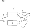
- Fig. 1 schematically a device 1 for the stimulation of neurons with a morbid synchronous and oscillatory neuronal activity is shown.
- the device 1 consists of a control and analysis unit 10, a stimulation unit 11 and a measuring unit 12.
- the control and analysis unit 10 performs, among other things, a control of the stimulation unit 11.
- the control and analysis unit 10 generates control signals 21, which are received by the stimulation unit 11.
- the stimulation unit 11 which may in particular contain a plurality of stimulation elements, generates stimuli 22, which are administered to a patient, on the basis of the control signals 21.
- the stimuli 22 may be mechanically tactile stimuli and / or thermal stimuli, wherein the mechanically tactile stimuli may be, in particular, tactile, vibratory, vibrotactile or skin-applied proprioceptive stimuli.
- the stimuli 22 can be perceived by the patient in particular consciously.
- the stimulation unit 11 and in particular the control and analysis unit 10 are non-invasive units, ie, during operation of the Device 1 are located outside the patient's body and are not surgically implanted in the body of the patient.
- the stimulation effect achieved by the stimuli 22 is controlled with the aid of the measuring unit 12.
- the measuring unit 12 receives one or more measurement signals 23 measured on the patient, optionally converts these into electrical signals 24 and supplies them to the control and analysis unit 10.
- the pathological neuronal activity in the stimulated target area or a region connected to the target area can be measured, wherein the neuronal activity of this area correlates sufficiently closely with the neuronal activity of the target area (eg muscle activity).
- the control and analysis unit 10 processes the signals 24, z.
- the signals 24 may be amplified and filtered, and the processed signals 24 analyzed.
- the control and analysis unit 10 in particular controls the stimulation unit 11.
- the control and analysis unit 10 may include a processor, e.g. As a microcontroller included.
- the stimulation methods described herein may be stored as software code in a memory associated with the control and analysis unit 10.
- the measuring unit 12 includes one or more sensors that measure signals that enable it, in particular with the aid of an adequate data analysis, (a) a "phase locking", ie a phase synchronization of a strictly periodic pulse train on the one hand and the Phase of pathological oscillatory activity on the other hand; and (b) detecting a decrease or increase in the amplitude of pathological oscillatory activity.
- the sensors of the measuring unit 12 further allow (c) a stimulus-induced reset to detect the phase of pathological oscillatory activity.
- sensors non-invasive sensors can be used, for. Chronic or intermittent electroencephalography (EEG) or electromyography (EMG) or magnetoencephalography (MEG) sensors (SQUIDS).
- EEG electroencephalography
- EMG electromyography
- MEG magnetoencephalography
- the neural activity can also be determined indirectly by measuring the tremor or by measuring movements by means of accelerometers or gyroscopes or by measuring the activation of the autonomic nervous system by measuring the skin conductance. It is also possible to find mood values that are recorded by the patient in portable devices, eg. As smartphones, can be used to control the stimulation success.
- the sensors may be implanted in the body of the patient.
- invasive sensors for example, epicortical electrodes, Tiefenhirnelektroden for the measurement of z.
- electrodes to be attached to peripheral nerves can be used as sensors.
- the individual components of the device 1, in particular the control and analysis unit 10, the stimulation unit 11 and / or the measuring unit 12, are structurally separated from each other.
- the device 1 can therefore also be understood as a system.
- the device 1 can be used in particular for the treatment of neurological or psychiatric diseases, z. Parkinson's disease, essential tremor, tremor due to multiple sclerosis and other pathological tremors, dystonia, epilepsy, depression, chronic pain syndromes, movement disorders, cerebellar diseases, obsessive-compulsive disorders, dementia, Alzheimer's disease, Tourette's syndrome, autism, post-stroke disorders, spasticity, tinnitus, sleep disorders, schizophrenia , Irritable bowel syndrome, addictions, borderline personality disorder, attention deficit hyperactivity disorder, attention deficit hyperactivity disorder, gambling addiction, neurosis, craving, anorexia, eating disorders, burnout syndrome, fibromyalgia, migraine, cluster headache, generalized headache, Neuralgia, ataxia, tic disorder or hypertension, as well as other disorders characterized by pathologically increased neuronal synchronization.
- Parkinson's disease essential tremor, tremor due to multiple sclerosis and other pathological tremor
- the above-mentioned diseases can be caused by a disturbance of the bioelectrical communication of neuron assemblies that are connected in specific circuits.
- a neuron population generates persistently pathological neuronal activity and possibly associated pathological connectivity (network structure).
- a large number of neurons synchronously form action potentials, ie the neurons involved fire excessively synchronously.
- the diseased neuron population has an oscillatory neuronal activity, ie, the neurons fire rhythmically.
- the mean frequency of the morbid rhythmic activity of the affected neuronal bandages is in the range of 1 to 30 Hz, but may be outside this range. In healthy people, however, the neurons fire qualitatively different, eg. B. in an uncorrelated manner.
- Fig. 1 the device 1 is shown during a CR stimulation.
- the brain 26 or spinal cord 26 of the patient at least one neuron population 27 has a morbidly synchronous and oscillatory neuronal activity as described above.
- the stimulation unit 11 administers the stimuli 22 to the patient in such a way that the stimuli 22 are received via receptors and from there via the nervous system to the pathologically active neuron population 27 in the brain 26 and / or spinal cord 26.
- the stimuli 22 are designed such that the pathologically synchronous activity of the neuron population 27 is desynchronized as a result of the stimulation.
- a reduction in the coincidence rate of the neurons caused by the stimulation can lead to a lowering of the synaptic weights and thus to a loss of the tendency to produce morbid synchronous activity.
- the mechanical tactile and / or thermal stimuli 22 applied by the stimulation unit 11 are picked up by receptors located in or under the skin and forwarded to the nervous system. These receptors include, for example, Merkel cells, Ruffini bodies, Meissner bodies and hair follicle receptors, which act in particular as receptors for the tactile stimuli 22.
- the vibratory stimuli 22 are aimed primarily at the depth sensitivity.
- the vibratory stimuli 22 may be received by receptors located in the skin, muscles, subcutaneous tissue, and / or tendons of the patient.
- the receptors for the vibratory stimuli 22 are exemplified by the father-Pacini bodies, which convey vibration sensations and accelerations.
- the thermal stimuli 22 are absorbed by the thermoreceptors of the skin. These are warm receptors (also called heat receptors, warm sensors or heat sensors) and cold sensors (also cold sensors, cold receptors or cold receptors called). In the human skin, the cold sensors are more superficial, the warm receptors a little deeper.
- the targeted stimulation of certain areas of the brain or spinal cord is made possible by the somatotopic assignment of body regions to these areas. Due to the somatotopic structure of the nerve conduction pathways and associated brain areas, different neurons are stimulated by mechanical tactile and / or thermal stimuli, which are applied at different points on the body surface.
- the stimulation elements may be attached to the foot, lower leg, and thighs or to the patient's hand, forearm, and upper arm to thereby stimulate certain neurons.
- the stimulation unit 11 can accordingly separately stimulate different regions of the brain 26 or spinal cord 26 by relaying the applied stimuli 22 via nerve leads to different target areas located in the brain 26 and / or spinal cord 26.
- the target areas may be stimulated during stimulation with possibly different and / or time-delayed stimuli 22.
- the neuron population 27 which has a pathologically synchronous and oscillatory neuronal activity, is administered stimuli 22, which in the neuron population 27 effect a so-called reset, the phase of the neuronal activity of the stimulated neurons.
- the phase of the stimulated neurons is brought to or close to a certain phase value, e.g. 0 ° (in practice it is not possible to set a specific phase value exactly, but this is not necessary for successful CR stimulation).
- the phase of neuronal activity of the diseased neuron population 27 is controlled by targeted stimulation.
- the phase of neuronal activity of the diseased neuron population 27 at the different stimulation sites can be reset at different times.
- the diseased neuron population 27, whose neurons were previously synchronous and active at the same frequency and phase, is split into several subpopulations, which in Fig. 1 are shown schematically and are identified by the reference numerals 28, 29, 30 and 31 (for example, four subpopulations are shown here).
- the neurons continue to be in synch after resetting the phase and continue to fire at the same pathological frequency, but each of the subpopulations 28 to 31 has the neuronal activity phase imposed by the stimulation stimulus. This means that the neuronal activities of the individual subpopulations 28 to 31 after resetting their phases continue to have an approximately sinusoidal course with the same pathological frequency, but different phases.
- the condition created by the stimulation is unstable with at least two subpopulations, and the entire neuron population 27 is rapidly approaching a state of complete desynchronization in which the neurons fire uncorrelated.
- the desired state ie the complete desynchronization, is thus not immediately available after the time-shifted (or phase-shifted) application of the phase-recovering stimuli 22, but usually occurs within a few periods or even less than one period of the pathological frequency.
- One theory for explaining the stimulation success is based on the fact that the ultimately desired desynchronization is made possible by the morbidly increased interaction between the neurons.
- a self-organization process is used, which is responsible for the morbid synchronization. It causes a division of a total population 27 into subpopulations 28 to 31 with different phases followed by desynchronization. In contrast, without pathologically enhanced interaction of the neurons, no desynchronization would occur.
- CR stimulation can reorganize the connectivity of the disordered neural networks so that long-lasting therapeutic effects can be achieved.
- the achieved synaptic remodeling is of great importance for the effective treatment of neurological or psychiatric disorders.
- the following describes a calibration performed with the device 1 to determine the optimal stimulus parameters for non-invasive CR stimulation.
- a so-called entrainment test is first carried out.
- the control and analysis unit 10 controls the stimulation unit 11 in such a way that the stimulation unit 11 scans at least part of the body surface of the patient along a path and periodically applies stimuli 22, ie, the periodic stimuli 22 are not stationary but "migrate". while scanning over the body surface.
- the control and analysis unit 10 selects at least two regions on the body surface of the patient along the path, in which the phase synchronization between the periodic application of the stimuli 22 and the neuronal activity of the stimulated neurons each having a local maximum. Subsequently, CR stimulation is performed on the at least two selected areas.
- control and analysis unit 10 controls the stimulation unit 11 in such a way that it applies stimuli 22 in the at least two selected areas, which effects a phase reset of the neuronal activity of the stimulated neurons.
- the stimuli 22 applied in the at least two regions are offset in time from one another.
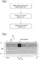
- the above embodiment may be further developed by adding further steps to the calibration shown in the flow chart of FIG Fig. 2 are summarized.
- the entrainment test described above is carried out in a first step.
- a pair test is performed in which stimuli are applied at two different locations to select one or more effective pairs for CR stimulation.
- a group test is carried out, which provides for the application of stimuli to at least two and typically more than two different locations.
- the device 1 enables an independent, automatically performed, electrophysiologically based calibration of the stimulation parameters, which requires significantly lower stimuli than conventional calibrations.
- the phase entrainment used here is a dynamic process that is effective at very low stimuli.
- Weaker stimuli have the advantage that the calibration performed with these stimuli is much more accurate. The reason for this is that the weaker stimuli are anatomically more selective, as they are reach fewer neurons, namely only those that optimally match the applied stimulus (and not adjacent neuron populations in the brain, which are stimulated with increasing stimulus strength).
- the calibration is performed at a stimulus intensity, at which the therapy is actually performed.
- weaker stimuli are less stressful for patients, in particular pain patients. For example, even lighter touches or thermal stimuli of patients with chronic pain syndromes, eg. B. with Sudeck's disease or neuralgia, as unpleasant or even painful.
- the calibration performed with the device 1 is significantly faster compared to conventional calibrations. This prevents fatigue of the patient and the associated deterioration of the quality of the data, d. H. of the results. It is therefore much more pleasant for the patient, does not require unreasonable compliance (patient cooperativity) and is well applicable in practice.
- the device 1 (i) allows the therapy to be carried out effectively, (ii) to avoid side effects, and (iii) to make the examinations to be made as short as possible, practicable, and bearable for the patient.
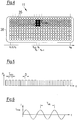
- the stimulation unit 11 here comprises an array of stimulation elements 35.
- Each of the stimulation elements 35 can generate mechanical tactile and / or thermal stimuli.
- the stimulation elements 35 are in the present embodiment part of a cuff 36 which can be attached to a body part of the patient, for example an arm, for stimulation.
- the array consequently consists of LxM stimulation elements 35.
- Each of the stimulation elements 35 can be individually controlled by the control and analysis unit 10.
- the cuff 36 with the array of the stimulation elements 35 makes it possible to periodically apply stimuli, wherein the locations at which the stimuli are applied, can change continuously. In this way, larger parts of the body surface can be scanned so that by means of analysis of the stimulus-induced neuronal activity suitable areas and distances between these areas for the therapeutic multi-channel stimulation can be determined.
- corresponding actuators could, of course, also slide over the body surface for this purpose.
- larger arrays of stimulation elements 35 z. B. by means of the cuff 36 on the body of the patient and to vary the activated groups of stimulation elements 35 in time.
- the stimulation elements 35 can be controlled by the control and analysis unit 10 so that the activation of the stimulation elements 35 z. B. travels along the sleeve 36.
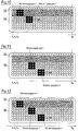
- Fig. 3 Exemplary is in Fig. 3 the wandering activation of a 3x3 group of stimulation elements 35 is shown.
- the direction of movement is indicated by an arrow.
- the stimulation elements 35 activated at a specific time form a 3 ⁇ 3 group and are shown in black.
- the activation group corresponds to an area on the body surface of the patient that is stimulated by the stimulation elements 35 included in the activation group. Only stimulation elements 35 that are at least partially within the 3x3 form of the activation group generate stimuli in the present embodiment.
- All other stimulation elements 35 ie, those stimulation elements which are completely outside the 3x3 form of the activation group, do not generate any stimuli. As the activation group travels across the cuff 36, the area where mechanical tactile and / or thermal stimuli are generated similarly migrates across the body surface of the patient.
- each stimulation element 36 is a respective actuator which is mounted on the body surface and can be deflected from its rest position to press into the body surface and thereby produce the desired stimulus.
- Fig. 4 is the activation of a 3x3 group of stimulation elements 36 compared to Fig. 3 already half a step further to the right.
- the vibration amplitude of the right and left vertical groups of three of the wandering activation is not maximum (shown in dark gray).
- non-linear interpolation methods can also be used.
- front X F (t) can be analogous z.
- B. also consider the position of the centroid of the group activation, which in Fig. 3 is at x k-1 .
- a periodic sequence P (t) of stimuli is applied.
- the periodic sequence P (t) is schematically shown in FIG Fig. 5 shown.
- this sequence is a smoother, non-rectangular sequence.
- the product is calculated from global periodic sequence P (t) and local amplitude Ai, m (t), ie P (t) Ai, m (t).
- the total vibration signal of a specific actuator is thus P (t) Ai, m (t) V (t), where V (t) is a high-frequency vibration, ie z. B. is a sine or square wave with a frequency of 250 Hz, for example. V (t) may also be a low frequency sine or square wave in the range of 0.25 to 50 Hz.
- the actuators (or vibrators) triggered by P (t) can also be pressed into the skin, so that the actuators deflected in this way do not oscillate about the zero line (vibrate), but about the displacement Po. In this case, the entire vibration signal is z. P (t) [Ai, m (t) V (t) + Po].
- a l, m (t) thus indicates the amplitude of each actuator (at a respective 1, m) at a given time t. Further, Ai, m (t) indicates the place where the in Fig. 3 exemplified activated group of actuators is located at the respective time t.
- P (t) consists of a periodic sequence of pulses.
- the pulses determine the periods at which stimuli are applied. During the periods between pulses, when P (t) equals zero, no stimuli are applied.
- the periodic sequence P (t) has the period T stim .
- the duration D stim of the pulse, ie the duration of a stimulation interval may range from 10 to 1000 ms.
- the pulses of the periodic sequence P (t) may in particular be identical.
- the period T stim is chosen close to the middle period of the pathological oscillation.
- For the respective disease characteristic pathological frequency bands that is, in accordance with the pathological rhythms to be desynchronized with the CR stimulation) or adjusted by feedback by measuring the pathological neural activity to be desynchronized via sensors and determining the frequency peak in the pathological frequency band known to those skilled in the art.
- a literature value can be used for the middle period of the pathological oscillation, and the period T stim used for the stimulation can be reduced from this literature value by z. B. to ⁇ 5%, ⁇ 10% or ⁇ 20%.
- the vibratory stimuli may also have another shape, eg. B. a rectangular shape.
- the deflection l max of a respective stimulation element 35 for generating the vibration V (t) can be in the range of 0.1 to 0.5 mm or up to 5 mm.
- a stimulation element 35 may have a force of e.g. B. exert about 2 N on the body surface of the patient.
- each stimulation element 35 can be designed such that it can generate a predetermined temperature T temp on the body surface of the patient or in a deeper region.
- the temperature T temp may be above or below the temperature T o existing in the target area without application of the thermal stimulus, ie, the target area may be heated or cooled.
- the temperature T temp can z. B. in the range of 22 to 42 ° C.
- the temperature T 0 is usually the body temperature of the patient.
- the stimulation elements 35 are the outputs of optical fibers, which are in particular fed by a common laser. The laser light can be distributed to the light guides with a suitable control such that the desired application of thermal stimuli is achieved.
- the total thermal signal of a stimulation element 35 is calculated from P (t) H l, m (t), where P (t) is the periodic sequence of pulses as described above in connection with FIG Fig. 5 and H l, m (t) is formed analogously to A l, m (t) and indicates the temperature generated by each stimulation element 35 (at a respective l, m) at a given time t.
- H l, m (t) indicates the location at which the activated group of stimulation elements 35 is located at the respective time t.
- the phase entrainment between P (t) and the pathologically rhythmic neural activity is calculated in a sliding window.
- areas on the body surface of the patient are identified along the path, in which the phase synchronization between P (t) and the pathologically rhythmic neuronal activity of the stimulated neurons each have a local maximum.
- the window length should be chosen so that it corresponds to at least 10, better 50 or even 100 middle periods of the diseased neuronal rhythm. This results in the speed of movement of the activation front X F (t). As the window length increases, the spatial resolution increases, as does the examination time. In practice, a multi-step approach has proven itself: first scan large parts of the body with a smaller window length, To roughly detect areas of the body with good phase entrainment in order to then scan in detail only those particular body parts with a larger window length.
- the starting point of the activated group of stimulation elements 35 this is the left edge of the cuff 36 in the examples of FIG Fig. 3 and 4 , as well as the way the activation travels can take different forms and be chosen in different ways.
- the shape of the activation group ie the 3x3 group in the examples of Fig. 3 and 4 may be predetermined or may be adjusted by the user, ie a physician, healthcare professionals or the patient, e.g. B. via appropriate switch.
- each stimulation element 35 or smaller groups of stimulation elements 35 may be associated with pressure switches in the cuff 36 or else the user may use a tablet, eg. As an iPad, or the like set the shape of the activation group.
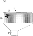
- Fig. 7 schematically shows a tablet 37, z. B. an iPad, via which the start configuration of the activation group is set.
- a corresponding group for. B. by means of a touch screen marked.
- the associated stimulation elements 35 can be activated thereby, whereby z. B. by the feedback of the patient ("Where do you feel the activation?") Or (only during this test phase) flashing of belonging to the corresponding stimulation elements 35 LEDs on the cuff 36, the user sees where the activation takes place.
- the tablet 37 is preferably cordless connected to the cuff 36.
- the latter is connected to a battery and optionally also to a control unit for the patient.
- the control unit allows the patient to easily operate the cuff 36 without having to use the tablet 37 extra.
- battery and control unit can be structurally combined with the sleeve 36.
- the shape of the activation group can be slowly varied according to an embodiment.
- the value of the extension z is used for the phase entrainment analysis instead of the position of the activation front in this case. In this way, configurations of the activation group to the individual anatomy and physiology of the patient, in particular the size of the receptive fields, automatically adjusted and thus optimized.
- the path of the activation group can be specified or chosen randomly or z. B. by means of snaps in the cuff 36 or by means of the tablet 37 can be adjusted.
- the user z. B. pretend on the tablet 37 more anatomically or physiologically preferred target positions.
- the activation group departs the path predetermined by these locations and determined by the usual interpolation methods.
- the entrainment test has the advantage over other tests that it is much faster and more sensitive.
- the low stimulus level in the entrainment test allows greater anatomical accuracy, as smaller neuron populations are irritated. This is important for the calibration of the CR stimulation, since this over the individual stimulation channels should be stimulated separately as possible, ideally even disjoint subpopulations.
- the entrainment test is based on the determination of the occurrence of a phase synchronization between a periodic stimulus and the neuronal rhythm of the morbidly synchronous and oscillatory neuron population.
- phase shift can be "built in”, which does not change the results, and also brings no advantages.
- the period T stim may be varied deterministically or stochastically or mixed deterministically-stochastically slowly in time, with the changes in the pacing rate f stim are at least an order of magnitude slower compared to the time scale of the oscillation under investigation.
- the phase ⁇ 2 (t) of the neuronal rhythm to be examined is determined from the measurement signal 23 and in particular by Hilbert transformation from the signal determined by means of bandpass filtering or "empirical mode decomposition", which represents the pathological oscillatory activity.
- the "empirical mode decomposition” allows a parameter-independent determination of physiologically relevant modes in different frequency ranges in comparison to bandpass filtering (cf. NE Huang et al .: The empirical mode decomposition and the Hilbert spectrum for nonlinear and non-stationary time series analysis. Proc. R. Soc. A: Math. Phys. Closely. Sci. 454, 903-995 (1998 )).
- the combination "empirical mode decomposition” followed by Hilbert transformation is called Hilbert-Huang transformation (cf. NE Huang et al .; A confidence limit for the empirical mode decomposition and Hilbert spectral analysis. Proceedings of the Royal Society of London Series A 459, 2317-2345 (2003 )).
- the phase ⁇ 2 (t) of the neuronal rhythm to be examined can also be determined by means of wavelet analysis. In addition to the instantaneous (time-dependent) phase ⁇ 2 (t) of the neuronal oscillation to be investigated, this additionally gives the instantaneous (time-dependent) amplitude thereof.
- n and m are small integers.
- the n: m phase difference modulo 2n is determined at times t 1 , t 2 ,..., T N.
- n: m phase synchronization is characterized by the occurrence of one or more accumulation values of ⁇ n, m (t) (cf. P. Tass, MG Rosenblum, J. Weule, J. Kurths, A. Pikovsky, J. Volkmann, A. Schnitzler and H.-J. Friend: Detection of n: m Phase Locking from noisysy Data: Application to Magnetoencephalography. Phys. Rev. Lett.
- n and m result from the ratio of stimulation frequency f stim to the dominant spectral frequency peak .
- amplitude effects can also be determined simply by analysis of the spectral power density-of a predefined frequency band known to the person skilled in the art or of one or more empirical modes extracted from the data or by means of wavelet analysis.
- a pre-stimulus baseline can be determined in a time window F pre with a length that corresponds to ten to thousand times the mean period of the oscillation to be examined: For the baseline determination of the amplitude A (t) of the neuronal rhythm is in the time window F pre z. For example, the 99th percentile of this distribution or simply the maximum is taken as the baseline value for A (t). If the signals due to artifacts should not be of the highest quality, because z. For example, if artifact elimination was not used upstream of EEG signals, then a lower percentile than baseline could be chosen (if the artifacts should have large amplitude values). Such a procedure is familiar to the person skilled in the art.
- a baseline of the n: m phase synchronization can z.
- B. be determined by in the time window F pre, so to speak, a sham stimulation is performed. That is, in the non-stimulated time window F pre , n: m phase synchronization is performed with a virtual periodic stimulus sequence. Another way to determine would be z. For example, replace the real stimulus-derived signals with surrogate data and then determine the n: m phase synchronization. Such procedures are known to those skilled in the art.
- a pair Test performed in which phase-recovering stimuli are applied in two different areas on the body surface of the patient to select effective pairs for CR stimulation.
- the pair test is performed immediately after the entrainment test, without first determining optimal individual stimuli using a phase resetting analysis.
- Fig. 8 schematically shows a pair test.
- two activation groups selected beforehand by means of the entrainment test ie areas on the body surface of the patient, are used to apply mechanically tactile and / or thermal stimuli 40 in the respective area on the body surface. Due to the somatotopic association, the stimuli 40 applied in the selected regions stimulate a respective subpopulation of the neuron population with the pathologically synchronous and oscillatory activity. The stimuli 40 are designed to reset the phase of the morbid synchronous and oscillatory neuronal activity of each stimulated subpopulation. If more than two activation groups have been selected as the result of the entrainment test, the pair test is preferably carried out with adjacent activation groups in each case.
- the stimulation elements 35 in each of the two activation groups 1 and 2 generate the phase-reset stimuli 40 in a sequence periodically with the period T stim .
- each sequence comprises three stimuli 40, but the sequences may also contain further stimuli 40.
- the break which can also be dispensed with, may in particular amount to an integer multiple of the period T stim .
- the time delay between the sequences of different activation groups T stim / 2, ie, the stimulation of the activation group 2 is T stim / 2 delayed in time to stimulate the activation group 1, so that the stimulation of the respective subpopulations also takes place with a time delay. Due to this time offset, the phases of the stimulated subpopulations are reset at different times. Except for the time offset the stimulations carried out by the activating groups 1 and 2 z. B. be identical.
- Pairwise stimulation is considered successful if there is no increase in amplitude A (t) of the pathological oscillation (ie no enhancement of the synchronization of the signal-generating pathologically synchronized neuron population) or even a slight decrease (corresponding to a weak desynchronization). That is, the amplitude A (t) of the neuronal rhythm must not increase compared to a baseline time window F pre . Rather, the amplitude A (t) should decrease or at least remain unchanged compared to the baseline time window F pre .
- a pair test will either be performed for all possible pairs that can be formed from the selected activation groups or, as faster, e.g. B. along a preferred axis, z. For example, along a belt worn on the abdomen or from the fingers toward shoulders, going from the first activation group to the next next suitable activation group - and then to the next next, etc. This saves time.
- You can z. For example, from the matrix of all pair comparisons, the best three-, four-, five-, six- (etc., eg up to tens) groups consisting of 3, 4, 5, 6, ... , Extract 10 activation groups, ie areas on the body surface of the patient. Unsuitable pairs of activation groups, the z. B. the pathologisehe amplify neural synchronization, are replaced by more appropriate pairs.
- Each activation group consisting of the respective stimulation elements 35 just as in the pair test, applies a sequence of phase-reverting stimuli 40 in the respective area on the body surface of the patient.
- the phase-recovering stimuli 40 are applied within a sequence periodically with the period T stim .
- each sequence comprises three stimuli 40, but the sequences may also contain more stimuli 40. After each sequence a certain break is kept and the sequence is repeated afterwards. Alternatively, the break can also be waived.
- the time delay between the sequences of adjacent activation groups is T stim / 4, since four activation groups are tested out in the group test.
- the time delay of adjacent channels would be T stim / N.
- the order in which the activation groups generate the stimuli 40 is varied.
- the stimuli generated by the N activation groups 40 z. B. be identical.
- the control and analysis unit 10 checks whether, in the application of the stimuli 40 via the selected group of activation groups, the pathologically synchronous and oscillatory neuronal activity of the stimulated neurons is suppressed and in particular desynchronized.
- the effectiveness of CR stimulation over the groups determined as described above is determined by the amplitude criterion as described in the pair test and / or by clinical determination, e.g. By clinical scores or simple clinical observation by an experienced physician or other therapist. If none of the selected groups are effective, new groups must be selected based on the pair matrix, or the full pair matrix must be determined.
- the pair test is dispensed with and after completion of the entrainment test, a group test is performed immediately. All, z.
- four activation groups selected during the entrainment assay are used to apply CR stimulation.
- the stimulation success can be checked in particular by means of a threshold value comparison. Depending on which signals are used to determine the stimulation success, different threshold comparisons result. If z. B. the pathological neuronal synchronization via the sensors of the measuring unit 12, z. As EEG electrodes or low electrodes (as LFP signal), measured, is sufficient to reduce the synchronization by z. At least 20% compared to the situation without stimulation, to determine a sufficient stimulation success.
- an insufficient stimulation success can be determined if the pathological neuronal synchronization is not reduced by the application of the stimuli 40 by at least one predetermined value. If symptoms of the patient are used to determine stimulation success, it will depend on the type of related clinical parameters, which decrease is considered clinically relevant improvement. Such acceptance values (eg in the sense of the so-called minimal clinically perceptible improvement) are known to the person skilled in the art.
- a suitable (initial) activation group in Fig. 10 this is exemplified by the activation group 1, starting from a second activation group, in Fig. 10 this exemplifies the activation group 2, introduced and slowly away from the initial activation group (as in Fig. 10 ) or towards this (not shown) moves.
- the in Fig. 8 performed stimulation, which are stimulated by the activation groups 1 and 2 at any time covered areas on the body surface of the patient.
- the path of the movement can be predetermined or set by the user as explained above.
- the starting point of the activation group 2 may be close to the activation group 1 or coincide with the starting point of the activation group 1.
- a suitable removal of both activation groups can be recognized by a good stimulation effect (electrophysiolgic good desynchronization or clinical good symptom reduction). Once this has been achieved, the distance should not be further increased in order to use a sufficient number of activating groups for the subsequent therapeutic stimulation.
- this method can be used in two ways.
- a first possibility is the pairwise testing of further suitable pairs of activation groups, ie the activation group 2 just determined becomes the new starting activation group, as described in US Pat Fig. 11 is shown, and it is added a further activation group, namely the activation group 3.
- the starting point of the activation group 3 may be close to the activation group 2 or coincide with the starting point of the activation group 3.
- the two activation groups 1 and 2 identified as suitable are set.
- An activation group 3 is added, and their distance varies along a predetermined or user-selected path, as exemplified in FIG Fig. 12 is shown.
- the starting point of the activation group 3 may be close to the activation group 2 or may coincide with the starting point of the activation group 3.
- phase reset of the synchronous neural activity is typically done by means of an ensemble of identical stimuli.
- One way that is well-known to those skilled in the art for analyzing the phase reset is to perform a "phase resetting” analysis as described, for example, in the article " Stochastic phase resetting of two-coupled phase oscillators stimulated at different times "by PA Tass (published in Physical Review E 67, 2003, pages 051902-1 to 051902-15 ) is described.
- the phase used here for calculating the phase reset is z. B. by means of the Hilbert transformation from the means of bandpass filtering or "empirical mode decomposition" signal representing the pathological oscillatory activity, determined (the latter allows compared to the bandpass filtering a parameter-independent determination of physiologically relevant modes in different frequency ranges, see.
- the empirical mode decomposition and the Hilbert spectrum for nonlinear and non-stationary time series analysis "by NE Huang et al. (Published in Proceedings of the Royal Society of London Series A, 1998, Vol. 454, pages 903 to 995 ); the combination "empirical mode decomposition” followed by Hilbert transformation is called Hilbert-Huang transformation, cf.
- phase reset is achieved when the phase resetting index exceeds the 99th percentile of the pre-stimulus distribution of the phase resetting index (cf. Fig. 4 in " Stochastic phase resetting of two-phase oscillators stimulated at different times "by PA Tass ). If medically a stronger phase-recovering effect is desirable, higher thresholds, e.g. B. twice or three times the 99th percentile of the pre-stimulus distribution of the phase resetting index.
- phase reset can be assumed to be approximate if the maximum amount of the stimulus response exceeds the 99th percentile of the pre-stimulus distribution of the averaged answer (or its double or triple) (cf. Fig. 6 in " Stochastic phase resetting of two-coupled phase oscillators stimulated at different times "by PA Tass, Phys. Rev. E 67, 051902-1 to 051902-15 (2003 )).
- Fig. 13 schematically shows a device 50 for EEG-based calibration of a mechanically tactile and / or thermal CR stimulation.
- Non-invasively fixed EEG electrodes 51, 52 which are connected via a cable 53, serve as a measuring unit and measure the EEG stimulus responses, which are forwarded via a cable 54 to the central control and analysis unit 10.
- a cuff 36 with an array of stimulation elements 35 is fixed to the forearm of the patient with Velcro straps.
- the activation groups selected by the calibration described above are indicated by dots.
- the cuff 36 is connected via a cable 55 or telemetrically connected to the control and analysis unit 10 housing the battery or the battery. In the case of the telemetric connection, the cuff 36 also houses a battery.
- Fig. 14 shows the device 50 from Fig. 13 wherein the cuff 36 is attached here belt-shaped on the abdomen of the patient.
Landscapes
- Health & Medical Sciences (AREA)
- Life Sciences & Earth Sciences (AREA)
- Engineering & Computer Science (AREA)
- Biomedical Technology (AREA)
- General Health & Medical Sciences (AREA)
- Veterinary Medicine (AREA)
- Public Health (AREA)
- Animal Behavior & Ethology (AREA)
- Heart & Thoracic Surgery (AREA)
- Pathology (AREA)
- Biophysics (AREA)
- Physics & Mathematics (AREA)
- Surgery (AREA)
- Molecular Biology (AREA)
- Medical Informatics (AREA)
- Radiology & Medical Imaging (AREA)
- Nuclear Medicine, Radiotherapy & Molecular Imaging (AREA)
- Neurology (AREA)
- Psychiatry (AREA)
- Psychology (AREA)
- Developmental Disabilities (AREA)
- Physiology (AREA)
- Neurosurgery (AREA)
- Epidemiology (AREA)
- Pain & Pain Management (AREA)
- Physical Education & Sports Medicine (AREA)
- Rehabilitation Therapy (AREA)
- Social Psychology (AREA)
- Child & Adolescent Psychology (AREA)
- Hospice & Palliative Care (AREA)
- Dentistry (AREA)
- Oral & Maxillofacial Surgery (AREA)
- Optics & Photonics (AREA)
- Vascular Medicine (AREA)
- Thermal Sciences (AREA)
- Electrotherapy Devices (AREA)
- Measurement And Recording Of Electrical Phenomena And Electrical Characteristics Of The Living Body (AREA)
- Thermotherapy And Cooling Therapy Devices (AREA)
- Percussion Or Vibration Massage (AREA)
Description
- Die Erfindung betrifft eine Vorrichtung zur Kalibrierung einer nicht-invasiven mechanisch taktilen und/oder thermischen Neurostimulation.
- Bei Patienten mit neurologischen oder psychiatrischen Erkrankungen, z. B. Morbus Parkinson, essentiellem Tremor, Tinnitus, Dystonie oder Zwangserkrankungen, sind Nervenzellverbände in umschriebenen Bereichen des Gehirns krankhaft, z. B. übersteigert synchron, aktiv. In diesem Fall bildet eine große Anzahl von Neuronen synchron Aktionspotentiale aus, d. h., die beteiligten Neuronen feuern übermäßig synchron. Beim Gesunden hingegen feuern die Neuronen in diesen Hirngebieten qualitativ anders, z. B. auf unkorrelierte Weise.
- Zur Behandlung derartiger Erkrankungen wurden Stimulationstechniken entwickelt, die gezielt krankhaft synchroner neuronaler Aktivität entgegenwirken. Die "Coordinated Reset" (CR)-Stimulation zeichnet sich hierbei durch große therapeutische Wirksamkeit und Sicherheit aus. Die nicht-invasive CR-Stimulation kann mit unterschiedlichen Reizmodalitäten realisiert werden: mittels sensorischer, z. B. vibrotaktiler Reize, mittels elektrischer oder magnetischer Reizung oder Ultraschallreizung peripherer Nerven oder mittels direkter elektrischer oder magnetischer Reizung oder Ultraschallreizung des Gehirns oder Rückenmarks.
- Die mechanisch taktile, insbesondere vibrotaktile CR-Stimulation lässt sich z. B. zur Behandlung der Parkinsonschen Erkrankung anwenden. Weitere Indikationen stellen z. B. Epilepsien (mittels vibrotaktiler CR-Stimulation), Funktionsstörungen nach Schlaganfall (mittels vibrotaktiler CR-Stimulation), chronische Schmerzsyndrome (mittels vibrotaktiler und/oder thermischer CR-Stimulation), Migräne (z. B. mittels visueller CR-Stimulation) dar. Des Weiteren lassen sich diese Erkrankungen und andere Hirnerkrankungen mit transkranieller Magnetstimulation oder direkter elektrischer Stimulation des Gehirns oder direkter Hirnstimulation mittels Ultraschall behandeln.
- Die nicht-invasiven CR-Stimulationsvorrichtungen und -verfahren sind deutlich nebenwirkungsärmer und kostengünstiger als invasive CR-Stimulationsvorrichtungen und -verfahren und sind damit für eine größere Anzahl von Patienten zugänglich.
- Von zentraler Bedeutung für die Wirksamkeit der CR-Stimulation ist, dass (i) die applizierten Reize die zu stimulierende Neuronenpopulation auf invasive oder nicht-invasive Weise tatsächlich erreichen, d. h., dass nicht an falschen Stellen des Körpers gereizt wird, und (ii) dass diese Reizung an hinreichend verschiedenen Stellen des Körpers erfolgt, so dass hinreichend verschiedene neuronale Subpopulationen stimuliert werden. Bei invasiver CR-Stimulation wird die optimale Lokalisation der implantierten Elektrode im Rahmen der OP-Planung u. a. über detaillierte anatomische Informationen, z. B. aus kernspintomographischen Untersuchungen, sichergestellt. Bei den nicht-invasiven Stimulationsverfahren hingegen ist die Kalibrierung der Lokalisation der verschiedenen nicht-invasiven Aktoren, z. B. der Platzierung der mechanisch taktilen oder thermischen Stimulatoren auf der Haut in Relation zum betroffenen Körperteil, bis jetzt ein Problem.
- In der Veröffentlichung der internationalen Patentanmeldung
WO 2013/117655 A1 wird eine Vorrichtung zum Stimulieren von Neuronen mit einer pathologischen synchronen und oszillatorischen neuronalen Aktivität beschrieben, wobei die Vorrichtung eine nicht-invasive Stimulationseinheit zum Anlegen von Stimuli zur Stimulation der Neuronen eines Patienten umfasst. - Der Erfindung liegt die Aufgabe zugrunde, eine Vorrichtung anzugeben, die eine vom Untersucher unabhängige, automatisch durchgeführte, elektrophysiologisch basierte Kalibrierung der Stimulationsparameter ermöglichen. Insbesondere sollen geeignete Bereiche auf der Körperoberfläche des Patienten für die mechanisch taktile und/oder thermische Stimulation schnell und zuverlässig ermittelt werden, um geeignete Zielorte im Gehirn reizen zu können, so dass die CR-Stimulation effektiv ist. Ferner soll die Erfindung ermöglichen, (i) die Therapie wirksam durchzuführen, (ii) Nebenwirkungen zu vermeiden, (iii) die zur Parametereinstellung durchzuführende Untersuchung möglichst kurz, praktikabel und für den Patienten erträglich zu gestalten.
- Die der Erfindung zugrunde liegende Aufgabenstellung wird durch die Merkmale der unabhängigen Ansprüche gelöst. Vorteilhafte Weiterbildungen und Ausgestaltungen der Erfindung sind in den Unteransprüchen angegeben.
- Die Erfindung wird nachfolgend in beispielhafter Weise unter Bezugnahme auf die Zeichnungen näher erläutert. In diesen zeigen:
- Fig. 1
- eine schematische Darstellung einer Vorrichtung zur mechanisch taktilen und/oder thermischen desynchronisierenden Neurostimulation während des Betriebs;
- Fig. 2
- ein Flussdiagramm zur Veranschaulichung der Kalibrierung der in
Fig. 1 dargestellten Vorrichtung; - Fig. 3 und 4
- schematische Darstellungen einer Manschette mit einem Array von Stimulationselementen und einer über die Manschette wandernden Aktivierungsgruppe;
- Fig. 5
- eine schematische Darstellung einer periodischen Abfolge von Reizen;
- Fig. 6
- eine schematische Darstellung eines Vibrationsreizes;
- Fig. 7
- eine schematische Darstellung einer Auswahl einer Aktivierungsgruppe mittels eines Tablets;
- Fig. 8
- eine schematische Darstellung einer CR-Stimulation mit zwei Aktivierungsgruppen;
- Fig. 9
- eine schematische Darstellung einer CR-Stimulation mit vier Aktivierungsgruppen;
- Fig. 10
- eine schematische Darstellung einer Ermittlung des optimalen Abstands zwischen zwei Aktivierungsgruppen;
- Fig. 11
- eine schematische Darstellung einer paarweisen Testung von Aktivierungsgruppen;
- Fig. 12
- eine schematische Darstellung einer iterativen Testung von Aktivierungsgruppen;
- Fig. 13
- eine schematische Darstellung einer Vorrichtung zur Kalibrierung einer mechanisch taktilen und/oder thermischen CR-Stimulation mit einer am Unterarm des Patienten fixierten Manschette; und
- Fig. 14
- eine schematische Darstellung einer Vorrichtung zur Kalibrierung einer mechanisch taktilen und/oder thermischen CR-Stimulation mit einer am Bauch des Patienten fixierten Manschette.
- In
Fig. 1 ist schematisch eine Vorrichtung 1 zur Stimulation von Neuronen mit einer krankhaft synchronen und oszillatorischen neuronalen Aktivität dargestellt. Mit Hilfe der Vorrichtung 1 lassen sich Stimulationsparameter einer nicht-invasiven Neurostimulation kalibrieren. Ferner kann die krankhaft synchrone und oszillatorische neuronale Aktivität unterdrückt und insbesondere desynchronisiert werden. Die Vorrichtung 1 besteht aus einer Steuer- und Analyseeinheit 10, einer Stimulationseinheit 11 und einer Messeinheit 12. Während des Betriebs der Vorrichtung 1 führt die Steuer- und Analyseeinheit 10 u. a. eine Steuerung der Stimulationseinheit 11 durch. Dazu erzeugt die Steuer- und Analyseeinheit 10 Steuersignale 21, die von der Stimulationseinheit 11 entgegengenommen werden. Die Stimulationseinheit 11, die insbesondere eine Mehrzahl von Stimulationselementen enthalten kann, erzeugt anhand der Steuersignale 21 Reize 22, die einem Patienten verabreicht werden. Die Reize 22 können mechanisch taktile Reize und/oder thermische Reize sein, wobei die mechanisch taktilen Reize insbesondere taktile, vibratorische, vibrotaktile oder über die Haut applizierte propriozeptive Reize sein können. Die Reize 22 können vom Patienten insbesondere bewusst wahrnehmbar sein. Die Stimulationseinheit 11 und insbesondere auch die Steuer- und Analyseeinheit 10 sind nicht-invasive Einheiten, d. h., während des Betriebs der Vorrichtung 1 befinden sie sich außerhalb des Körpers des Patienten und werden nicht operativ in den Körper des Patienten implantiert. - Der durch die Reize 22 erzielte Stimulationseffekt wird mit Hilfe der Messeinheit 12 kontrolliert. Die Messeinheit 12 nimmt ein oder mehrere am Patienten gemessene Messsignale 23 auf, wandelt diese gegebenenfalls in elektrische Signale 24 um und führt diese der Steuer- und Analyseeinheit 10 zu. Insbesondere kann mittels der Messeinheit 12 die pathologisch neuronale Aktivität in dem stimulierten Zielgebiet oder einem mit dem Zielgebiet verbundenen Gebiet gemessen werden, wobei die neuronale Aktivität dieses Gebiets mit der neuronalen Aktivität des Zielgebiets hinreichend eng korreliert (z. B. Muskelaktivität). Die Steuer- und Analyseeinheit 10 verarbeitet die Signale 24, z. B. können die Signale 24 verstärkt und gefiltert werden, und analysiert die verarbeiteten Signale 24. Anhand der Ergebnisse dieser Analyse steuert die Steuer- und Analyseeinheit 10 insbesondere die Stimulationseinheit 11 an. Zur Durchführung ihrer Aufgaben kann die Steuer- und Analyseeinheit 10 einen Prozessor, z. B. einen Mikrocontroller, enthalten. Die hierin beschriebenen Stimulationsverfahren können als Software-Code in einem der Steuer- und Analyseeinheit 10 zugeordneten Speicher abgelegt sein.
- Die Messeinheit 12 enthält ein oder mehrere Sensoren, die Signale messen, die es insbesondere mit Hilfe einer adäquaten Datenanalyse ermöglichen, (a) ein "phase locking", d. h. eine Phasensynchronisation, zwischen einem (bzgl. des Timings) strikt periodischem Pulszug einerseits und der Phase der pathologischen oszillatorischen Aktivität andererseits und (b) eine Ab- bzw. Zunahme der Amplitude der pathologischen oszillatorischen Aktivität nachzuweisen. In einer Ausgestaltung ermöglichen es die Sensoren der Messeinheit 12 weiterhin, (c) eine Stimulus-induzierte Zurücksetzung der Phase der pathologischen oszillatorischen Aktivität nachzuweisen.
- Als Sensoren können nicht-invasive Sensoren eingesetzt werden, z. B. chronisch oder intermittent genutzte Elektroenzephalographie (EEG)- oder Elektromyographie (EMG)-Elektroden oder Magnetenzephalographie (MEG)-Sensoren (SQUIDS). Die neuronale Aktivität kann auch indirekt durch Messung des Tremors oder durch Messung von Bewegungen mittels Akzelerometern oder Gyroskopen oder durch Messung der Aktivierung des autonomen Nervensystems mittels Messung des Hautleitwiderstands ermittelt werden. Es können auch Befindlichkeitswerte, die vom Patienten in portable Geräte, z. B. Smartphones, eingegeben werden, zur Kontrolle des Stimulationserfolgs verwandt werden.
- Alternativ können die Sensoren in den Körper des Patienten implantiert sein. Als invasive Sensoren können beispielsweise epikortikale Elektroden, Tiefenhirnelektroden zur Messung von z. B. lokalen Feldpotentialen (LFP), sub- oder epidurale Hirnelektroden, subkutane EEG-Elektroden und sub- oder epidurale Rückenmarkselektroden dienen. Des Weiteren können an peripheren Nerven zu befestigende Elektroden als Sensoren eingesetzt werden.
- Es kann durchaus vorgesehen sein, dass die einzelnen Komponenten der Vorrichtung 1, insbesondere die Steuer- und Analyseeinheit 10, die Stimulationseinheit 11 und/oder die Messeinheit 12, baulich voneinander getrennt sind. Die Vorrichtung 1 kann daher auch als System aufgefasst werden.
- Die Vorrichtung 1 kann insbesondere zur Behandlung von neurologischen oder psychiatrischen Erkrankungen eingesetzt werden, z. B. Morbus Parkinson, essentiellem Tremor, Tremor infolge von Multipler Sklerose sowie anderen pathologischen Tremores, Dystonie, Epilepsie, Depression, chronischen Schmerzsyndromen, Bewegungsstörungen, Kleinhirnerkrankungen, Zwangserkrankungen, Demenzerkrankungen, Morbus Alzheimer, Tourette-Syndrom, Autismus, Funktionsstörungen nach Schlaganfall, Spastik, Tinnitus, Schlafstörungen, Schizophrenie, Reizdarm-Syndrom, Suchterkrankungen, Borderline-Persönlichkeitsstörung, Aufmerksamkeits-Defizit-Syndrom, Aufmerksamkeits-Defizit-Hyperaktivitäts-Syndrom, Spielsucht, Neurosen, Fresssucht, Magersucht, Essstörungen, Burnout-Syndrom, Fibromyalgie, Migräne, Cluster-Kopfschmerz, allgemeiner Kopfschmerz, Neuralgie, Ataxie, Tic-Störung oder Hypertonie, sowie weiteren Erkrankungen, die durch krankhaft gesteigerte neuronale Synchronisation gekennzeichnet sind.
- Die vorstehend genannten Krankheiten können durch eine Störung der bioelektrischen Kommunikation von Neuronenverbänden, die in spezifischen Schaltkreisen zusammengeschlossen sind, verursacht werden. Hierbei generiert eine Neuronenpopulation anhaltend krankhafte neuronale Aktivität und möglicherweise eine damit verbundene krankhafte Konnektivität (Netzwerkstruktur). Dabei bilden eine große Anzahl von Neuronen synchron Aktionspotentiale aus, d. h., die beteiligten Neuronen feuern übermäßig synchron. Hinzu kommt, dass die kranke Neuronenpopulation eine oszillatorische neuronale Aktivität aufweist, d. h., die Neuronen feuern rhythmisch. Im Fall von neurologischen oder psychiatrischen Erkrankungen liegt die mittlere Frequenz der krankhaften rhythmischen Aktivität der betroffenen Neuronenverbände etwa im Bereich von 1 bis 30 Hz, kann aber auch außerhalb dieses Bereichs liegen. Bei gesunden Menschen feuern die Neuronen hingegen qualitativ anders, z. B. auf unkorrelierte Weise.
- In
Fig. 1 ist die Vorrichtung 1 während einer CR-Stimulation dargestellt. Im Gehirn 26 oder Rückenmark 26 des Patienten weist mindestens eine Neuronenpopulation 27 eine wie vorstehend beschriebene krankhaft synchrone und oszillatorische neuronale Aktivität auf. Die Stimulationseinheit 11 verabreicht dem Patienten die Reize 22 derart, dass die Reize 22 über Rezeptoren aufgenommen werden und von dort über das Nervensystem an die krankhaft aktive Neuronenpopulation 27 im Gehirn 26 und/oder Rückenmark 26 weitergeleitet werden. Die Reize 22 sind so ausgestaltet, dass die krankhaft synchrone Aktivität der Neuronenpopulation 27 als Ergebnis der Stimulation desynchronisiert wird. Eine durch die Stimulation bewirkte Senkung der Koinzidenzrate der Neuronen kann zu einer Senkung der synaptischen Gewichte und somit zu einem Verlernen der Tendenz zur Produktion krankhaft synchroner Aktivität führen. - Die von der Stimulationseinheit 11 applizierten mechanisch taktilen und/oder thermischen Reize 22 werden von in oder unter der Haut gelegenen Rezeptoren aufgenommen und an das Nervensystem weitergeleitet. Zu diesen Rezeptoren zählen beispielsweise Merkel-Zellen, Ruffini-Körperchen, Meissner-Körperchen und Haarfollikelrezeptoren, die insbesondere als Rezeptoren für die taktilen Reize 22 wirken. Die vibratorischen Reize 22 zielen vorwiegend auf die Tiefensensibilität ab. Die vibratorischen Reize 22 können von in der Haut, den Muskeln, dem Subkutangewebe und/oder den Sehnen des Patienten gelegenen Rezeptoren aufgenommen werden. Als Rezeptoren für die vibratorischen Reize 22 seien beispielhaft die Vater-Pacini-Körperchen genannt, die Vibrationsempfindungen und Beschleunigungen vermitteln. Die thermischen Reize 22 werden von den Thermorezeptoren der Haut aufgenommen. Dies sind Warmrezeptoren (auch Wärmerezeptoren, Warmsensoren oder Wärmesensoren genannt) und Kaltsensoren (auch Kältesensoren, Kaltrezeptoren oder Kälterezeptoren genannt). In der Haut des Menschen liegen die Kaltsensoren mehr oberflächlich, die Warmrezeptoren etwas tiefer.
- Die gezielte Stimulation bestimmter Bereiche des Gehirns oder Rückenmarks wird durch die somatotope Zuordnung von Körperregionen zu diesen Bereichen ermöglicht. Aufgrund der somatotopen Gliederung der Nervenleitungsbahnen und zugehörigen Hirngebiete werden durch mechanisch taktile und/oder thermische Reize, die an unterschiedlichen Stellen der Körperoberfläche appliziert werden, unterschiedliche Neuronen stimuliert. Beispielsweise können die Stimulationselemente am Fuß, Unterschenkel und Oberschenkel oder aber an der Hand, dem Unterarm und Oberarm des Patienten angebracht werden, um dadurch bestimmte Neuronen zu stimulieren.
- Die Stimulationseinheit 11 kann demnach unterschiedliche Bereiche des Gehirns 26 oder Rückenmarks 26 separat stimulieren, indem die applizierten Reize 22 über Nervenleitungen an unterschiedliche Zielgebiete, die im Gehirn 26 und/oder Rückenmark 26 liegen, weitergeleitet werden. Die Zielgebiete können während der Stimulation mit eventuell unterschiedlichen und/oder zeitversetzten Reizen 22 stimuliert werden.
- Bei der CR-Stimulation werden der Neuronenpopulation 27, die eine krankhaft synchrone und oszillatorische neuronale Aktivität aufweist, Reize 22 verabreicht, welche in der Neuronenpopulation 27 ein Zurücksetzen, einen sogenannten Reset, der Phase der neuronalen Aktivität der stimulierten Neuronen bewirken. Durch das Zurücksetzen wird die Phase der stimulierten Neuronen unabhängig von dem aktuellen Phasenwert auf einen oder nahe zu einem bestimmten Phasenwert, z. B. 0°, gesetzt (in der Praxis ist es nicht möglich, einen bestimmten Phasenwert exakt einzustellen, dies ist für eine erfolgreiche CR-Stimulation aber auch nicht erforderlich). Somit wird die Phase der neuronalen Aktivität der krankhaften Neuronenpopulation 27 mittels einer gezielten Stimulation kontrolliert. Da es ferner möglich ist, die krankhafte Neuronenpopulation 27 an unterschiedlichen Stellen zu stimulieren, kann die Phase der neuronalen Aktivität der krankhaften Neuronenpopulation 27 an den unterschiedlichen Stimulationsstellen zu unterschiedlichen Zeitpunkten zurückgesetzt werden. Im Ergebnis wird dadurch die krankhafte Neuronenpopulation 27, deren Neuronen zuvor synchron und mit gleicher Frequenz und Phase aktiv waren, in mehrere Subpopulationen aufgespalten, die in
Fig. 1 schematisch dargestellt sind und mit den Bezugszeichen 28, 29, 30 und 31 gekennzeichnet sind (beispielhaft sind hier vier Subpopulationen dargestellt). Innerhalb einer der Subpopulationen 28 bis 31 sind die Neuronen nach dem Zurücksetzen der Phase weiterhin synchron und feuern auch weiterhin mit derselben pathologischen Frequenz, aber jede der Subpopulationen 28 bis 31 weist bezüglich ihrer neuronalen Aktivität die Phase auf, die ihr durch den Stimulationsreiz aufgezwungen wurde. Dies bedeutet, dass die neuronalen Aktivitäten der einzelnen Subpopulationen 28 bis 31 nach dem Zurücksetzen ihrer Phasen weiterhin einen in etwa sinusförmigen Verlauf mit derselben pathologischen Frequenz haben, aber unterschiedliche Phasen. - Bedingt durch die krankhafte Interaktion zwischen den Neuronen ist der durch die Stimulation erzeugte Zustand mit mindestens zwei Subpopulationen instabil, und die gesamte Neuronenpopulation 27 nähert sich schnell einem Zustand kompletter Desynchronisation, in welchem die Neuronen unkorreliert feuern. Der gewünschte Zustand, d. h. die komplette Desynchronisation, ist somit nach der zeitversetzten (oder phasenverschobenen) Applikation der phasenrücksetzenden Reize 22 nicht sofort vorhanden, sondern stellt sich meist innerhalb weniger Perioden oder gar in weniger als einer Periode der pathologischen Frequenz ein.
- Eine Theorie zur Erklärung des Stimulationserfolgs basiert darauf, dass die letztlich gewünschte Desynchronisation durch die krankhaft gesteigerte Interaktion zwischen den Neuronen erst ermöglicht wird. Hierbei wird ein Selbstorganisationsprozess ausgenutzt, der für die krankhafte Synchronisation verantwortlich ist. Derselbe bewirkt, dass auf eine Aufteilung einer Gesamtpopulation 27 in Subpopulationen 28 bis 31 mit unterschiedlichen Phasen eine Desynchronisation folgt. Im Gegensatz dazu würde ohne krankhaft gesteigerte Interaktion der Neuronen keine Desynchronisation erfolgen.
- Darüber hinaus kann durch die CR-Stimulation eine Neuorganisation der Konnektivität der gestörten neuronalen Netzwerke erzielt werden, so dass lang anhaltende therapeutische Effekte bewirkt werden können. Der erzielte synaptische Umbau ist von großer Bedeutung für die wirksame Behandlung neurologischer oder psychiatrischer Erkrankungen.
- Im Folgenden wird eine Kalibrierung beschrieben, die mit der Vorrichtung 1 durchgeführt wird, um damit die optimalen Reizparameter für die nicht-invasive CR-Stimulation zu ermitteln.
- Gemäß einer Ausgestaltung wird zunächst ein sogenannter Entrainment-Test durchgeführt. Dazu steuert die Steuer- und Analyseeinheit 10 die Stimulationseinheit 11 derart an, dass die Stimulationseinheit 11 zumindest einen Teil der Körperoberfläche des Patienten entlang eines Pfads abrastert und dabei periodisch Reize 22 appliziert, d. h., die periodischen Reize 22 sind nicht stationär, sondern "wandern" während der Abrasterung über die Körperoberfläche. Anhand der in Reaktion auf die periodische Applikation der Reize 22 aufgenommenen Messsignale 23 wählt die Steuer- und Analyseeinheit 10 mindestens zwei Bereiche auf der Körperoberfläche des Patienten entlang des Pfads aus, in welchen die Phasensynchronisation zwischen der periodischen Applikation der Reize 22 und der neuronalen Aktivität der stimulierten Neuronen jeweils ein lokales Maximum aufweist. Anschließend wird an den mindestens zwei ausgewählten Bereichen eine CR-Stimulation durchgeführt. Dazu steuert die Steuer- und Analyseeinheit 10 die Stimulationseinheit 11 derart an, dass diese in den mindestens zwei ausgewählten Bereichen Reize 22 appliziert, die eine Phasenrücksetzung der neuronalen Aktivität der stimulierten Neuronen bewirken. Die in den mindestens zwei Bereichen applizierten Reize 22 sind gegeneinander zeitversetzt.
- Die vorstehende Ausgestaltung kann weitergebildet werden, indem der Kalibrierung weitere Schritte hinzugefügt werden, die im Flussdiagramm von
Fig. 2 zusammengefasst sind. Dazu wird in einem ersten Schritt der vorstehend beschriebene Entrainment-Test durchgeführt. Danach wird in einem zweiten Schritt ein Paar-Test vorgenommen, bei dem Reize an zwei verschiedenen Orten appliziert werden, um ein oder mehrere wirksame Paare für die CR-Stimulation zu selektieren. Schließlich wird in einem dritten Schritt ein Gruppen-Test durchgeführt, der die Applikation von Reizen an mindestens zwei und typischerweise mehr als zwei verschiedenen Orten vorsieht. - Die Vorrichtung 1 ermöglicht eine vom Untersucher unabhängige, automatisch durchgeführte, elektrophysiologisch basierte Kalibrierung der Stimulationsparameter, die im Vergleich zu herkömmlichen Kalibrierungen mit deutlich geringeren Reizstärken auskommt. Das hier genutzte Phasen-Entrainment ist ein dynamischer Vorgang, der bei sehr geringen Reizstärken effektiv ist. Schwächere Reize haben den Vorteil, dass die mit diesen Reizen durchgeführte Kalibrierung deutlich genauer ist. Der Grund hierfür ist, dass die schwächeren Reize anatomisch selektiver sind, da sie weniger Neuronen erreichen, nämlich nur die, welche optimal zu dem applizierten Reiz passen (und nicht benachbarte Neuronenpopulationen im Gehirn, die bei steigender Reizstärke mit stimuliert werden). Die Kalibrierung wird bei einer Reizintensität durchgeführt, bei der auch die Therapie tatsächlich durchgeführt wird. Schwächere Reize sind darüber hinaus für Patienten, insbesondere Schmerzpatienten weniger belastend. Beispielsweise können schon leichtere Berührungen oder Wärmereize von Patienten mit chronischen Schmerzsyndromen, z. B. mit Morbus Sudeck oder Neuralgien, als unangenehm oder sogar schmerzhaft empfunden werden.
- Darüber hinaus ist die mit der Vorrichtung 1 durchgeführte Kalibrierung im Vergleich zu herkömmlichen Kalibrierungen deutlich schneller. Dies beugt einer Ermüdung des Patienten und der damit verbundenen Verschlechterung der Qualität der Daten, d. h. der Ergebnisse vor. Sie ist dadurch für den Patienten deutlich angenehmer, erfordert keine unzumutbare Compliance (Kooperativität der Patienten) und ist in der Praxis gut anwendbar.
- Zusammenfassend ermöglicht es die Vorrichtung 1, (i) die Therapie wirksam durchzuführen, (ii) Nebenwirkungen zu vermeiden und (iii) die zur Parametereinstellung durchzuführenden Untersuchungen möglichst kurz, praktikabel und für den Patienten erträglich zu gestalten.
- Im Folgenden werden die einzelnen zur Kalibrierung der Stimulationsparameter durchzuführenden Schritte detaillierter erläutert. Dies geschieht anhand eines Ausführungsbeispiels der Stimulationseinheit 11, welches in
Fig. 3 schematisch dargestellt ist. Die Stimulationseinheit 11 umfasst hier ein Array von Stimulationselementen 35. Jedes der Stimulationselemente 35 kann mechanisch taktile und/oder thermische Reize erzeugen. Die Stimulationselemente 35 sind in dem vorliegenden Ausführungsbeispiel Bestandteil einer Manschette 36, die zur Stimulation an einem Körperteil des Patienten, beispielsweise einem Arm, befestigt werden kann. InFig. 3 stehen l und m für die Reihen bzw. Spalten des Arrays aus Stimulationselementen 35, wobei l = 1,..., L und m = 1,..., M gilt. Insgesamt besteht das Array folglich aus LxM Stimulationselementen 35. Jedes der Stimulationselemente 35 kann von der Steuer- und Analyseeinheit 10 individuell angesteuert werden. - Die Manschette 36 mit dem Array aus den Stimulationselementen 35 ermöglicht es, periodisch Reize zu applizieren, wobei die Stellen, an denen die Reize appliziert werden, sich kontinuierlich ändern können. Auf diese Weise können größere Teile der Körperoberfläche abgerastert werden, so dass mittels Analyse der reizinduzierten neuronalen Aktivität geeignete Bereiche und Abstände zwischen diesen Bereichen für die therapeutische Mehrkanal-Stimulation ermittelt werden können.
- Hierfür könnten prinzipiell natürlich auch entsprechende Aktoren über die Körperoberfläche gleiten. Einfacher ist es jedoch, größere Arrays von Stimulationselementen 35 z. B. mittels der Manschette 36 am Körper des Patienten zu fixieren und die aktivierten Gruppen von Stimulationselementen 35 zeitlich zu variieren. Z. B. können die Stimulationselemente 35 von der Steuer- und Analyseeinheit 10 so angesteuert werden, dass die Aktivierung der Stimulationselemente 35 z. B. entlang der Manschette 36 wandert.
- Beispielhaft ist in
Fig. 3 die wandernde Aktivierung einer 3x3-Gruppe von Stimulationselementen 35 gezeigt. Die Stimulationselemente 35 in der zweit- bis viertobersten Zeile, die durch eine Schraffur hervorgehoben sind, bilden sozusagen den Pfad, entlang dem die Aktivierung der Stimulationselemente 35 wandert. Die Bewegungsrichtung ist durch einen Pfeil dargestellt. Die zu einem bestimmten Zeitpunkt aktivierten Stimulationselemente 35 bilden eine 3x3-Gruppe und sind schwarz dargestellt. Die Aktivierungsgruppe entspricht einem Bereich auf der Körperoberfläche des Patienten, der von den von der Aktivierungsgruppe umfassten Stimulationselementen 35 stimuliert wird. Nur Stimulationselemente 35, die zumindest teilweise innerhalb der 3x3-Form der Aktivierungsgruppe liegen, erzeugen in dem vorliegenden Ausführungsbeispiel Reize. Alle übrigen Stimulationselemente 35, d. h., diejenigen Stimulationselemente, die vollständig außerhalb der 3x3-Form der Aktivierungsgruppe liegen, erzeugen keine Reize. Wenn die Aktivierungsgruppe über die Manschette 36 wandert, wandert der Bereich, in dem mechanisch taktile und/oder thermische Reize erzeugt werden, in entsprechender Weise über die Körperoberfläche des Patienten. - Wir bezeichnen die Position der Front der wandernden 3x3-Aktivierungsgruppe mit XF. Die Front und damit die gesamte 3x3-Aktivierung kann z. B. mit konstanter Geschwindigkeit vom linken Ende der Manschette 36 zum rechten Ende der Manschette 36 wandern. In
Fig. 3 befindet sich die Front bei xk. Im Folgenden soll die Erfindung beispielhaft anhand der Realisation mit vibrotaktilen Stimulationselementen 36 erklärt werden. In diesem Fall ist jedes Stimulationselement 36 ein jeweiliger Aktor, der auf der Körperoberfläche angebracht ist und aus seiner Ruhelage ausgelenkt werden kann, um in die Körperoberfläche einzudrücken und dadurch den gewünschten Reiz zu erzeugen. - Die Amplitude der zur vibrotaktilen Stimulation eingesetzten Stimulationselemente 36, d. h. der Aktoren, zur Zeit t wird mit Ai,m(t) bezeichnet. Hiermit lautet die Amplitude der Vibration der Stimulationselemente 36 in der k-ten Spalte, d. h. bei xk, in der zweit- bis viertobersten Zeile folgendermaßen:
Für XF(t) ≤ xk-1: Al,k(t) = 0 Für xk-1 < XF(t) ≤ xk: 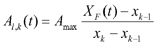
Für xk ≤ XF(t) ≤ xk+3: Al,k(t) = Amax Für xk+3 < XF(t) < xk+4: 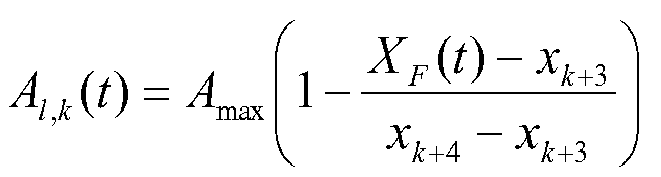
Für XF(t) ≥ xk+4: Al,k(t) = 0 wobei l = 2, 3, 4 gilt. - In
Fig. 4 ist die Aktivierung einer 3x3-Gruppe von Stimulationselementen 36 im Vergleich zurFig. 3 bereits einen halben Schritt weiter nach rechts gewandert. Durch Interpolation ist die Vibrationsamplitude der rechten und linken vertikalen Dreiergruppe der wandernden Aktivierung nicht maximal (dunkelgrau dargestellt). - Neben der hier verwandten linearen Interpolation können auch nichtlineare Interpolationsverfahren verwandt werden. Statt der Front XF(t) kann man analog z. B. auch die Position des Schwerpunkts der Gruppen-Aktivierung betrachten, welche in
Fig. 3 bei xk-1 liegt. - Während die Aktivierungsfront XF(t) mit konstanter Geschwindigkeit langsam entlang der Manschette 36 von links nach rechts, z. B. vom Handgelenk zur Ellenbeuge, wandert, wird eine periodische Abfolge P(t) von Reizen appliziert. Die periodische Abfolge P(t) ist schematisch in
Fig. 5 dargestellt. Typischerweise handelt es sich, u. a. wegen der Trägheit der Aktoren, bei dieser Abfolge um eine glattere, nicht rechteckförmige Abfolge. Um den Zeitgang der Vibrationsamplitude eines konkreten Aktors zu bestimmen, wird das Produkt aus globaler periodischer Abfolge P(t) und lokaler Amplitude Ai,m(t), also P(t)Ai,m(t) berechnet. Das gesamte Vibrationssignal eines konkreten Aktors lautet folglich P(t)Ai,m(t)V(t), wobei V(t) eine hochfrequente Vibration, also z. B. eine Sinus- oder Rechteckschwingung mit einer Frequenz von beispielsweise 250 Hz ist. Es kann sich bei V(t) auch um eine niederfrequente Sinus- oder Rechteckschwingung im Bereich von 0,25 bis 50 Hz handeln. In einer weiteren Ausgestaltung können die Aktoren (bzw. Vibratoren) - getriggert durch P(t) - auch in die Haut gedrückt werden, so dass die auf diese Weise ausgelenkten Aktoren nicht um die Nulllinie oszillieren (vibrieren), sondern um die Auslenkung Po. In diesem Fall lautet das gesamte Vibrationssignal z. B. P(t)[Ai,m(t)V(t) + Po]. - Al,m(t) gibt folglich die Amplitude jedes Aktors (bei einem jeweiligen l, m) zu einem gegebenen Zeitpunkt t an. Ferner gibt Ai,m(t) den Ort an, an dem sich die in
Fig. 3 beispielhaft dargestellte aktivierte Gruppe von Aktoren zu dem jeweiligen Zeitpunkt t befindet. - P(t) besteht aus einer periodischen Abfolge von Pulsen. Die Pulse bestimmen die Zeiträume, zu denen Reize appliziert werden. Während der Zeiträume zwischen den Pulsen, wenn P(t) gleich Null ist, werden keine Reize appliziert. Wie
Fig. 5 zeigt, weist die periodische Abfolge P(t) die Periode Tstim auf. Die Stimulationsfrequenz fstim = 1/Tstim liegt typischerweise im Bereich von 0,25 bis 30 Hz. Die Dauer Dstim der Pulse, d. h. die Dauer eines Stimulationsintervalls, kann im Bereich von 10 bis 1000 ms liegen. Die Pulse der periodischen Abfolge P(t) können insbesondere identisch sein. - Die Periode Tstim wird nahe bei der mittleren Periode der pathologischen Oszillation gewählt. Die Stimulationsfrequenz fstim = 1/Tstim wird gemäß dem Fachmann bekannten Vorwissen bzgl. der für die jeweilige Erkrankung charakteristischen pathologischen Frequenzbänder (also in Übereinstimmung mit den pathologischen Rhythmen, die mit der CR-Stimulation desynchronisiert werden sollen) gewählt oder mittels Feedback durch Messung der zu desynchronisierenden pathologischen neuronalen Aktivität über Sensoren und Bestimmung des Frequenzpeaks im dem Fachmann bekannten pathologischen Frequenzband angepasst. Ferner kann ein Literaturwert für die mittlere Periode der pathologischen Oszillation herangezogen werden, und die für die Stimulation verwendete Periode Tstim kann von diesem Literaturwert um z. B. bis zu ± 5%, ± 10% oder ± 20% abweichen.
-
Fig. 6 zeigt als Beispiel für die Vibration V(t) eine kontinuierliche Sinusschwingung mit einer Frequenz fvib = 1/Tvib im Bereich von 0,25 bis 300 Hz, insbesondere im Bereich von 0,25 bis 50 Hz oder 100 bis 300 Hz, wobei Tvib die Periodendauer des Vibrationsreizes ist. Anstelle einer Sinusform können die vibratorischen Reize auch eine andere Form aufweisen, z. B. eine Rechteckform. Die Auslenkung lmax eines jeweiligen Stimulationselements 35 zur Erzeugung der Vibration V(t) kann im Bereich von 0,1 bis 0,5 mm oder bis zu 5 mm liegen. Bei einer Frequenz fvib von 300 Hz kann ein Stimulationselement 35 eine Kraft von z. B. etwa 2 N auf die Körperoberfläche des Patienten ausüben. - Für den Fall, dass thermische Reize von den Stimulationselementen 35 appliziert werden sollen, kann jedes Stimulationselement 35 derart ausgestalten sein, dass es auf der Körperoberfläche des Patienten oder in einem tieferliegenden Bereich eine vorgegebene Temperatur Ttemp erzeugen kann. Die Temperatur Ttemp kann ober- oder unterhalb der ohne die Applikation des thermischen Reizes im Zielgebiet herrschenden Temperatur To liegen, d. h., das Zielgebiet kann erhitzt oder gekühlt werden. Die Temperatur Ttemp kann z. B. im Bereich von 22 bis 42 °C liegen. Die Temperatur T0 ist in der Regel die Körpertemperatur des Patienten. In einer Ausgestaltung handelt es sich bei den Stimulationselementen 35 um die Ausgänge von Lichtleitern, die insbesondere von einem gemeinsamen Laser gespeist werden. Das Laserlicht kann mit einer geeigneten Steuerung derart auf die Lichtleiter verteilt werden, dass die gewünschte Applikation thermischer Reize erzielt wird.
- Das gesamte Thermosignal eines Stimulationselements 35 berechnet sich aus P(t)Hl,m(t), wobei P(t) die periodische Abfolge von Pulsen ist, wie sie vorstehend im Zusammenhang mit
Fig. 5 erläutert wurde, und Hl,m(t) analog zu Al,m(t) gebildet ist und die von jedem Stimulationselement 35 (bei einem jeweiligen l, m) zu einem gegebenen Zeitpunkt t erzeugte Temperatur angibt. Insbesondere wird durch Hl,m(t) der Ort angegeben, an dem sich die aktivierte Gruppe von Stimulationselementen 35 zu dem jeweiligen Zeitpunkt t befindet. - Während die Aktivierung der Stimulationselemente 35 z. B. von links nach rechts über die Manschette 36 entlang eines Pfads wandert, wird das Phasen-Entrainment zwischen P(t) und der krankhaft rhythmischen neuronalen Aktivität in einem gleitenden Fenster berechnet. Dabei werden Bereiche auf der Körperoberfläche des Patienten entlang des Pfads identifiziert, in denen die Phasensynchronisation zwischen P(t) und der krankhaft rhythmischen neuronalen Aktivität der stimulierten Neuronen jeweils ein lokales Maximum aufweist. Die Fensterlänge sollte so gewählt werden, dass sie mindestens 10, besser 50 oder sogar 100 mittleren Perioden des krankhaften neuronalen Rhythmus entspricht. Hieraus ergibt sich die Bewegungsgeschwindigkeit der Aktivierungsfront XF(t). Mit wachsender Fensterlänge wächst die räumliche Auflösung, aber auch die Untersuchungszeit. In der Praxis hat sich auch ein mehrschrittiges Vorgehen bewährt: zuerst mit einer kleineren Fensterlänge große Körperpartien abrastern, um Körperstellen mit gutem Phasen-Entrainment grob zu detektieren, um danach nur diese besonderen Körperstellen mit größerer Fensterlänge detailliert abzurastern.
- Der Startpunkt der aktivierten Gruppe von Stimulationselementen 35, dies ist der linke Rand der Manschette 36 in den Beispielen von
Fig. 3 und4 , sowie der Weg, welchen die Aktivierung zurücklegt, können unterschiedliche Formen annehmen und auf unterschiedliche Weise gewählt werden. Die Form der Aktivierungsgruppe, d. h. die 3x3-Gruppe in den Beispielen vonFig. 3 und4 , kann vorgegeben sein oder kann durch den Anwender, d. h. einen Arzt, medizinisches Fachpersonal oder den Patienten, eingestellt werden, z. B. über entsprechende Schalter. Beispielsweise können jedem Stimulationselement 35 oder kleineren Gruppen von Stimulationselementen 35 Druckschalter in der Manschette 36 zugeordnet sein oder aber der Anwender kann über ein Tablet, z. B. ein iPad, oder dergleichen die Form der Aktivierungsgruppe einstellen. -
Fig. 7 zeigt schematisch ein Tablet 37, z. B. ein iPad, über welches die Startkonfiguration der Aktivierungsgruppe eingestellt wird. Hierzu wird an dem Tablet 37 eine entsprechende Gruppe, z. B. mittels eines Touchscreens, markiert. Optional können die zugehörigen Stimulationselemente 35 hierdurch aktiviert werden, wodurch z. B. durch die Rückmeldung des Patienten ("Wo spüren Sie die Aktivierung?") oder ein (nur während dieser Testphase stattfindendes) Aufblinken der zu den entsprechenden Stimulationselementen 35 gehörenden LEDs auf der Manschette 36 der Anwender sieht, wo die Aktivierung erfolgt. Das Tablet 37 ist vorzugsweise schnurlos mit der Manschette 36 verbunden. Letztere ist mit einer Batterie und optional auch mit einer Steuereinheit für den Patienten verbunden. Die Steuereinheit erlaubt es dem Patienten, die Manschette 36 auf einfache Weise zu bedienen, ohne extra das Tablet 37 verwenden zu müssen. Batterie und Steuereinheit können mit der Manschette 36 auch baulich vereint sein. - Die Form der Aktivierungsgruppe kann gemäß einer Ausgestaltung langsam variiert werden. Z. B. kann die Form der Aktivierungsgruppe langsam variiert werden, indem vom Schwerpunkt ausgehend die Aktivierungsgruppe zentrisch um z% gestreckt wird, wobei z langsam vom Ausgangswert (100%) bis zu einem Maximalwert, z. B. 110% bei z = 10, variiert wird. Analog zu der Variation der Position der Aktivierungsfront wird für die Phasen-Entrainment-Analyse statt der Position der Aktivierungsfront in diesem Fall der Wert der Streckung z herangezogen. Auf diese Weise können Konfigurationen der Aktivierungsgruppe an die individuelle Anatomie und Physiologie des Patienten, insbesondere die Größe der rezeptiven Felder, automatisch angepasst und damit optimiert werden.
- Der Weg der Aktivierungsgruppe kann vorgegeben oder zufällig gewählt sein oder vom Anwender z. B. mittels Druckknöpfen in der Manschette 36 oder mit Hilfe des Tablets 37 eingestellt werden. Hierzu kann der Anwender z. B. auf dem Tablet 37 mehrere anatomisch bzw. physiologisch bevorzugte Zielpositionen vorgeben. Anschließend fährt die Aktivierungsgruppe den durch diese Orte vorgegebenen und mittels den üblichen Interpolationsverfahren ermittelten Weg ab.
- Die Auswahl der Orte bzw. Bereiche, an denen die für die Therapie des Patienten vorgesehenen Reize appliziert werden, erfolgt mit Hilfe eines Entrainment-Tests. Der Entrainment-Test hat den Vorteil gegenüber anderen Tests, dass er deutlich schneller und sensitiver ist. Außerdem ermöglicht die geringe Reizstärke beim Entrainment-Test eine größere anatomische Genauigkeit, da kleinere Neuronenpopulationen gereizt werden. Dies ist für die Kalibrierung der CR-Stimulation wichtig, da hierbei über die einzelnen Stimulationskanäle möglichst separate, im Idealfall sogar disjunkte Subpopulationen gereizt werden sollen.
- Der Entrainment-Test beruht auf der Ermittlung der Ausprägung einer Phasensynchronisation zwischen einem periodischen Reiz und dem neuronalen Rhythmus der krankhaft synchronen und oszillatorischen Neuronenpopulation. Die periodische Abfolge P(t), die beispielhaft in
Fig. 5 dargestellt ist, appliziert zu den Zeiten τ1, τ2,..., τK einen Reiz, wobei K die Anzahl der Reize bezeichnet. Da die Reizabfolge periodisch ist, ist die Stimulationsperiode Tstim konstant, d. h., es gilt Tstim = τj+i - τj für alle j = 1,..., K-1. Die zugehörige Stimulationsfrequenz, d. h. Repetitionsrate, lautet fstim = 1/Tstim. - Die Phase der periodischen Reizabfolge P(t) lautet ϕ1(t) = 2π(t - τ1)/Tstim (vgl. z. B. M. G. Rosenblum, A. S. Pikovsky, C. Schäfer, J. Kurths, P. A. Tass: Phase Synchronization: From Theory to Data Analysis. In: Moss F. (Ed.): Handbook of Biological Physics, Elsevier (2000)). Die so gewählte Phase verschwindet, wenn der erste Reiz appliziert wird: ϕ1(t) = 0.
- Alternativ kann auch eine Phasenverschiebung "eingebaut" werden, die nichts an den Ergebnissen verändert, und auch keine Vorteile mit sich bringt. Eine Phasenverschiebung kann dadurch "eingebaut" werden, dass entweder eine andere Startzeit gewählt wird ϕ1(t) = 2π(t - ξ)/Tstim, wobei ξ ≠ τ1 und ξ = konst gilt, oder indem eine Phasenverschiebung ϑ explizit dazu addiert wird: ϕ1(t) = 2π(t - τ1)/Tstim + ϑ, wobei ϑ = konst gilt. Die Periode Tstim kann auch eine zeitlich langsam variierende Funktion der Zeit sein: Tstim = χ(t). Insbesondere kann die Periode Tstim deterministisch oder stochastisch oder gemischt deterministisch-stochastisch langsam in der Zeit variiert werden, wobei die Änderungen der Stimulationsfrequenz fstim im Vergleich zur Zeitskala der zu untersuchenden Oszillation mindestens eine Größenordnung langsamer sind.
- Die Phase ϕ2(t) des zu untersuchenden neuronalen Rhythmus wird aus dem Messsignal 23 und insbesondere mittels Hilbert-Transformation aus dem mittels Bandpassfilterung bzw. "empirical mode decomposition" bestimmten Signal, welches die pathologische oszillatorische Aktivität repräsentiert, ermittelt. Die "empirical mode decomposition" ermöglicht im Vergleich zur Bandpassfilterung eine parameterunabhängige Bestimmung physiologisch relevanter Moden in verschiedenen Frequenzbereichen (vgl. N. E. Huang et al.: The empirical mode decomposition and the Hilbert spectrum for nonlinear and non-stationary time series analysis. Proc. R. Soc. A: Math. Phys. Eng. Sci. 454, 903-995 (1998)). Die Kombination "empirical mode decomposition" mit nachfolgender Hilbert-Transformation wird als Hilbert-Huang-Transformation bezeichnet (vgl. N. E. Huang et al.; A confidence limit for the empirical mode decomposition and Hilbert spectral analysis. Proceedings of the Royal Society of London Series A 459, 2317-2345 (2003)). Die Phase ϕ2(t) des zu untersuchenden neuronalen Rhythmus kann auch mittels wavelet-Analyse bestimmt werden. Neben der instantanen (zeitabhängigen) Phase ϕ2(t) der zu untersuchenden neuronalen Oszillation erhält man auf diese Weise zusätzlich deren instantane (zeitabhängige) Amplitude.
- Um den Grad der Phasensynchronisation zwischen dem Reiz und neuronalem Rhythmus zu bestimmen, betrachten wir die n:m-Phasendifferenz zwischen dem Reiz und dem neuronalen Rhythmus ψn,m(t) = nϕ1(t) - mϕ2(t), wobei n und m kleine ganze Zahlen sind. Auf diese Weise kann die Phasensynchronisation zwischen dem Reiz und einem neuronalen Rhythmus in unterschiedlichen Frequenzbändern untersucht werden. D. h., zur Untersuchung des Effekts der Stimulation auf neuronale Rhythmen muss man sich nicht auf den Rhythmus, der sich im selben Frequenzbereich wie die Reizfrequenz (n = m = 1) befindet, beschränken. Die n:m-Phasendifferenz modulo 2n lautet Φn,m(t) = [nϕ1(t) - mϕ2(t)]mod 2π.
- Bestimmt u. a. durch die Abtastrate wird zu den Zeiten t1, t2,..., tN die n:m-Phasendifferenz modulo 2n ermittelt. Hiermit erhalten wir die zugehörige Verteilung von Φn,m, welche

- Liegt keinerlei n:m-Phasensynchronisation vor, so ist die Verteilung der n:m-Phasendifferenz modulo 2n eine Gleichverteilung (bzw. kommt dieser hinreichend nahe). Im Gegensatz hierzu ist n:m-Phasensynchronisation durch das Auftreten von einem oder mehreren Häufungswerten von Φn,m(t) charakterisiert (vgl. P. Tass, M.G. Rosenblum, J. Weule, J. Kurths, A. Pikovsky, J. Volkmann, A. Schnitzler und H.-J. Freund: Detection of n:m Phase Locking from Noisy Data: Application to Magnetoencephalography. Phys. Rev. Lett. 81 (15), 3291-3294 (1998); M. G. Rosenblum, A. S. Pikovsky, C. Schäfer, J. Kurths, P. A. Tass: Phase Synchronization: From Theory to Data Analysis. In: Moss F. (Ed.): Handbook of Biological Physics, Elsevier (2000)).
- Das Auftreten einer n:m-Phasensynchronisation kann mittels unterschiedlicher Variablen bestimmt werden. Im Folgenden werden Beispiele angeführt:
- (i) Sollte die Verteilung von Φn,m einen (einzigen) Häufungswert aufweisen, so kann der zirkuläre Mittelwert dieser Verteilung berechnet werden:


- (ii) Deswegen sollte zudem (oder ausschließlich) ein Synchronisationsindex berechnet werden, der unabhängig von der Anzahl der Häufungswerte verlässliche Ergebnisse liefert. Zu diesem Zweck wird mit dem Kuiper-Test, der zirkulären Variante des Kolmogorov-Smirnov-Tests (vgl. E. Batschelet: Circular Statistics in Biology (Academic Press, London, 1981); N. H. Kuiper: Tests concerning random points in a circle. Proc. K. Ned. Akad. Wet., Ser. A: Math. Sci. 63, 38 (1960); P. A. Tass: Transmission of stimulus-locked responses in two coupled phase oscillators. Phys. Rev. E 69, 051909-1-24 (2004)), die Wahrscheinlichkeit bestimmt, mit der die Verteilung


- (iii) Eine weitere Möglichkeit ist ein auf der Shannon-Entropie der Verteilung
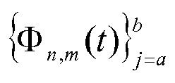
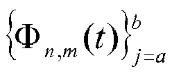


- Neben den stimulationsbedingten Effekten auf die Phase ϕ2(t) des neuronalen Rhythmus und damit die n:m-Phasendifferenz Φn,m werden auch stimulationsbedingte Effekte auf die Amplitude A(t) des neuronalen Rhythmus untersucht. n und m ergeben sich aus dem Verhältnis von Stimulationsfrequenz fstim zu dem dominanten spektralen Frequenzpeak. Die Analyse kann aber auch standardmäßig für einige wenige Paare von n und m (jeweils klein und ganzzahlig, z. B. n, m = 1, 2, 3) durchgeführt werden, z. B.: (n,m) = (1,1) = (1,2) = (2,1) = (2,3) = (3,2) =.... Es geht nicht nur darum, ob die Stimulation den neuronalen Rhythmus in einem n:m-Verhältnis in Takt bringt, sondern ob die Stimulation auch das Ausmaß der dem neuronalen Rhythmus zugrunde liegenden Synchronisation der Neuronen verändert. Ein Anstieg der Synchronisation innerhalb der stimulierten Neuronenpopulation führt zu einem Anwachsen der Amplitude A(t). Umgekehrt führt eine Abnahme der Synchronisation innerhalb der dem neuronalen Rhythmus zugrunde liegenden Neuronenpopulation zu einer Abnahme der Amplitude A(t). Für die Auswertung der Amplitudeneffekte sind somit Messungen in einem Vergleichsintervall (z. B. vor Verabreichung der Stimulation) durchzuführen. Alternativ können Amplitudeneffekte auch einfach durch eine Analyse der spektralen Leistungsdichte - eines vordefinierten, für die Erkrankung typischen und dem Fachmann bekannten Frequenzbandes oder einer bzw. mehrerer aus den Daten extrahierten empirical modes oder mittels wavelet-Analyse bestimmt werden.
- Zur Bestimmung der Signifikanz der durch die periodische Reizabfolge induzierten Phaseneffekte bzw. Amplitudeneffekte kann eine prä-Stimulus-Baseline in einem Zeitfenster Fpre mit einer Länge, die dem Zehn- bis Tausendfachen der mittleren Periode der zu untersuchenden Oszillation entspricht, bestimmt werden:
Zur Baseline-Bestimmung der Amplitude A(t) des neuronalen Rhythmus wird in dem Zeitfenster Fpre z. B. die 99te Perzentile dieser Verteilung oder einfach das Maximum als Baselinewert für A(t) genommen. Falls die Signale wegen Artefakten nicht von bester Qualität sein sollten, weil z. B. bei EEG-Signalen keine Artefakt-Elimination vorgeschaltet wurde, kann man auch eine niedrigere Perzentile als Baseline wählen (falls die Artefakte große Amplitudenwerte haben sollten). Ein derartiges Vorgehen ist dem Fachmann vertraut. - Eine Baseline der n:m-Phasensynchronisation kann z. B. dadurch bestimmt werden, indem in dem Zeitfenster Fpre sozusagen eine Sham-Stimulation durchgeführt wird. D. h., in dem Zeitfenster Fpre, in dem nicht stimuliert wird, wird eine n:m-Phasensynchronisation mit einer virtuellen periodischen Reizabfolge durchgeführt. Eine andere Möglichkeit zur Bestimmung wäre z. B., die echten unter Stimulation abgeleiteten Signale durch Surrogat-Daten zu ersetzen und hierfür dann die n:m-Phasensynchronisation zu bestimmen. Derartige Prozeduren sind dem Fachmann bekannt.
- Nachdem mit Hilfe des Entrainment-Tests Aktivierungsgruppen, d. h. Bereiche auf der Körperoberfläche des Patienten, ermittelt wurden, in welchen die Phasensynchronisation zwischen der periodischen Applikation der Reize und der neuronalen Aktivität der stimulierten Neuronen ausreichend hoch ist bzw. ein lokales Maximum aufweist, wird ein Paar-Test vorgenommen, bei dem phasenrücksetzende Reize in zwei verschiedenen Bereichen auf der Körperoberfläche des Patienten appliziert werden, um wirksame Paare für die CR-Stimulation zu selektieren. Der Paar-Test wird direkt nach dem Entrainment-Test durchgeführt, ohne dass zuvor noch optimale Einzelreize mittels einer "Phase resetting"-Analyse ermittelt werden.
-
Fig. 8 zeigt schematisch einen Paar-Test. Hier werden zwei zuvor mit Hilfe des Entrainment-Tests ausgewählte Aktivierungsgruppen, d. h. Bereiche auf der Körperoberfläche des Patienten herangezogen, um mechanisch taktile und/oder thermische Reize 40 in dem jeweiligen Bereich auf der Körperoberfläche zu applizieren. Aufgrund der somatotopen Zuordnung stimulieren die in den ausgewählten Bereichen applizierten Reize 40 eine jeweilige Subpopulationen der Neuronenpopulation mit der krankhaft synchronen und oszillatorischen Aktivität. Die Reize 40 sind dazu ausgelegt, die Phase der krankhaft synchronen und oszillatorischen neuronalen Aktivität der jeweils stimulierten Subpopulation zurückzusetzen. Sofern als Ergebnis des Entrainment-Tests mehr als zwei Aktivierungsgruppen ausgewählt wurden, wird der Paar-Test bevorzugt mit jeweils benachbarten Aktivierungsgruppen durchgeführt. - Die Stimulationselemente 35 in jeder der beiden Aktivierungsgruppen 1 und 2 erzeugen die phasenrücksetzenden Reize 40 in einer Sequenz periodisch mit der Periode Tstim. In dem vorliegenden Fall umfasst jede Sequenz drei Reize 40, die Sequenzen können allerdings auch weitere Reize 40 enthalten. Nach jeder Sequenz wird eine vorgegebene Pause eingehalten und die Sequenz wird danach wiederholt. Die Pause, auf die auch verzichtet werden kann, kann insbesondere ein ganzzahliges Vielfaches der Periode Tstim betragen. Ferner beträgt die zeitliche Verzögerung zwischen den Sequenzen unterschiedlicher Aktivierungsgruppen Tstim/2, d. h., die Stimulation der Aktivierungsgruppe 2 ist um Tstim/2 zeitversetzt zur Stimulation der Aktivierungsgruppe 1, so dass die Stimulation der jeweiligen Subpopulationen ebenfalls zeitversetzt erfolgt. Aufgrund dieses Zeitversatzes werden die Phasen der stimulierten Subpopulationen zu unterschiedlichen Zeitpunkten zurückgesetzt. Bis auf den Zeitversatz können die von den Aktivierungsgruppen 1 und 2 durchgeführten Stimulationen z. B. identisch sein.
- Ob über ein jeweiliges Paar von Aktivierungsgruppen effektiv stimuliert werden kann, bemisst sich an der von der Messeinheit 12 gemessenen Amplitude A(t) der pathologischen Oszillation. Eine paarweise Stimulation gilt dann als erfolgreich, wenn kein Amplitudenanstieg A(t) der pathologischen Oszillation (also keine Verstärkung der Synchronisation der das Signal generierenden pathologisch synchronisierten Neuronenpopulation) oder sogar eine leichte Abnahme (entspricht einer schwachen Desynchronisation) auftritt. D. h., die Amplitude A(t) des neuronalen Rhythmus darf im Vergleich zu einem Baseline-Zeitfenster Fpre nicht anwachsen. Vielmehr sollte die Amplitude A(t) im Vergleich zu dem Baseline-Zeitfenster Fpre abfallen oder zumindest unverändert bleiben. Man kann den unter Paar-Stimulation erzielten Wert der Amplitude A(t) z. B. einer Perzentile der Verteilung der Amplitude A(t) im Baseline-Zeitfenster Fpre zuordnen. Oder man kann entsprechende Verhältnisse berechnen.
- Ein Paar-Test wird entweder wird für alle möglichen Paare, die aus den ausgewählten Aktivierungsgruppen gebildet werden können, durchgeführt oder, da schneller, z. B. entlang einer Vorzugsachse, z. B. entlang eines am Bauch getragenen Gürtels oder von den Fingern in Richtung Schultern, vorgehend, von der ersten Aktivierungsgruppe zu der nächsten nächst geeigneten Aktivierungsgruppe - und von dieser dann zur wieder nächsten usw. Dies spart Zeit. Man kann z. B. auch aus der Matrix aller Paar-Vergleiche die besten Dreier-, Vierer-, Fünfer-, Sechser- (usw., z. B. bis zu Zehner-) Gruppen bestehend aus 3, 4, 5, 6,..., 10 Aktivierungsgruppen, d. h. Bereichen auf der Körperoberfläche des Patienten, extrahieren. Ungeeignete Paare von Aktivierungsgruppen, die z. B. die pathologisehe neuronale Synchronisation verstärken, werden ersetzt durch besser geeignete Paare.
- Die auf diese Weise bestimmten Gruppen werden im Gruppen-Test bzgl. ihrer Effektivität untersucht. Ein beispielhafter Gruppen-Test einer aus vier Aktivierungsgruppen bestehenden Gruppe ist beispielhaft in
Fig. 9 gezeigt. Jede aus den jeweiligen Stimulationselementen 35 bestehende Aktivierungsgruppe appliziert genauso wie beim Paar-Test eine Sequenz von phasenrücksetzenden Reizen 40 in dem jeweiligen Bereich auf der Körperoberfläche des Patienten. Die phasenrücksetzenden Reize 40 werden innerhalb einer Sequenz periodisch mit der Periode Tstim appliziert. In dem vorliegenden Beispiel umfasst jede Sequenz drei Reize 40, die Sequenzen können allerdings auch mehr Reize 40 enthalten. Nach jeder Sequenz wird eine bestimmte Pause eingehalten und die Sequenz danach wiederholt. Alternativ kann auf die Pause auch verzichtet werden. Ferner beträgt die zeitliche Verzögerung zwischen den Sequenzen benachbarter Aktivierungsgruppen Tstim/4, da vier Aktivierungsgruppen in dem Gruppen-Test ausgetestet werden. Für den allgemeinen Fall von N Aktivierungsgruppen würde die zeitliche Verzögerung benachbarter Kanäle Tstim/N betragen. Weiterhin ist es möglich, dass die Reihenfolge, in welcher die Aktivierungsgruppen die Reize 40 erzeugen, variiert wird. Ferner können die von den N Aktivierungsgruppen erzeugten Reize 40 z. B. identisch sein. - Die Steuer- und Analyseeinheit 10 prüft, ob bei der Applikation der Reize 40 über die ausgewählte Gruppe von Aktivierungsgruppen die krankhaft synchrone und oszillatorische neuronale Aktivität der stimulierten Neuronen unterdrückt und insbesondere desynchronisiert wird. Die Effektivität der CR-Stimulation über die wie oben beschrieben ermittelten Gruppen wird mit dem wie beim Paar-Test beschriebenen Amplitudenkriterium und/oder mittels klinischer Bestimmung, z. B. mittels klinischer Scores oder einfacher klinischer Beobachtung durch einen erfahrenen Arzt oder sonstigen Therapeuten, bestimmt. Sollte keine der ausgewählten Gruppen effektiv sein, müssen neue Gruppen anhand der Paar-Matrix ausgesucht werden, bzw. es muss die volle Paar-Matrix bestimmt werden.
- Gemäß einer Ausgestaltung wird auf den Paar-Test verzichtet und nach Abschluss des Entrainment-Tests wird sogleich ein Gruppen-Test durchgeführt. Alle, z. B. vier, im Zuge des Entrainment-Test ausgewählten Aktivierungsgruppen werden verwandt, um eine CR-Stimulation zu applizieren. Der Stimulationserfolg kann insbesondere mittels eines Schwellwertvergleichs überprüft werden. Je nachdem welche Signale zur Ermittlung des Stimulationserfolgs herangezogen werden, ergeben sich unterschiedliche Schwellwertvergleiche. Wird z. B. die krankhafte neuronale Synchronisation über die Sensoren der Messeinheit 12, z. B. EEG-Elektroden oder Tiefelektroden (als LFP-Signal), gemessen, reicht erfahrungsgemäß die Absenkung der Synchronisation um z. B. mindestens 20 % im Vergleich zur Situation ohne Stimulation, um einen ausreichenden Stimulationserfolg festzustellen. Gemäß einer Ausgestaltung kann ein nicht ausreichender Stimulationserfolg festgestellt werden, wenn sich die krankhafte neuronale Synchronisation durch die Applikation der Reize 40 nicht um mindestens einen vorgegebenen Wert verringert. Falls Symptome des Patienten zur Ermittlung des Stimulationserfolgs herangezogen werden, hängt es von der Art der verwandten klinischen Parameter ab, welche Abnahme als klinisch relevante Besserung anzusehen ist. Derartige Abnahmewerte (z. B. im Sinne der sog. minimalen klinisch wahrnehmbaren Verbesserung) sind dem Fachmann bekannt.
- In einer anderen Ausgestaltung wird von einer geeigneten (Ausgangs-) Aktivierungsgruppe, in
Fig. 10 ist dies beispielhaft die Aktivierungsgruppe 1, ausgehend eine zweite Aktivierungsgruppe, inFig. 10 die dies beispielhaft die Aktivierungsgruppe 2, eingeführt und langsam von der Ausgangs-Aktivierungsgruppe weg (wie inFig. 10 ) bzw. zu dieser hin (nicht gezeichnet) bewegt. Währenddessen wird die inFig. 8 gezeigte Stimulation durchgeführt, mit welcher die von den Aktivierungsgruppen 1 und 2 zu einem jeweiligen Zeitpunkt bedeckten Bereiche auf der Körperoberfläche des Patienten stimuliert werden. Der Pfad der Bewegung kann dabei vorgegeben oder wie oben erläutert vom Anwender eingestellt werden. Der Ausgangspunkt der Aktivierungsgruppe 2 kann nahe bei der Aktivierungsgruppe 1 liegen oder mit dem Ausgangspunkt der Aktivierungsgruppe 1 koinzidieren. Eine geeignete Entfernung beider Aktivierungsgruppen erkennt man durch eine guten Stimulationseffekt (elektrophysiolgisch eine gute Desynchronisation bzw. klinisch eine gute Symptomreduktion). Sobald dies erreicht ist, sollte der Abstand nicht weiter vergrößert werden, um insgesamt hinreichend viele Aktivierungsgruppen für die nachfolgende therapeutische Stimulation nutzen zu können. - Iterativ kann man bei dieser Methode nun prinzipiell zwei Wege beschreiten. Eine erste Möglichkeit ist die paarweise Testung weiterer geeigneter Paare von Aktivierungsgruppen, d. h., die gerade ermittelte Aktivierungsgruppe 2 wird zur neuen Ausgangs-Aktivierungsgruppe, wie dies in
Fig. 11 gezeigt ist, und es wird eine weitere Aktivierungsgruppe, nämlich die Aktivierungsgruppe 3 hinzugenommen. Die Aktivierungsgruppe 3 wird langsam von der Ausgangs-Aktivierungsgruppe 2 weg oder zu dieser hin bewegt, wobei mit den Aktivierungsgruppen 2 und 3 die inFig. 8 gezeigte Stimulation durchgeführt wird (mit N = 2), bis anhand der von der Messeinheit 12 aufgenommenen Messsignale 23 festgestellt wird, dass ein guter Stimulationseffekt erzielt wird, z. B. eine mit Hilfe der Messeinheit 12 beobachtete gute Desynchronisation vorliegt. Der Ausgangspunkt der Aktivierungsgruppe 3 kann nahe bei der Aktivierungsgruppe 2 liegen oder mit dem Ausgangspunkt der Aktivierungsgruppe 3 koinzidieren. Sind nacheinander schließlich alle geeigneten Paare von Aktivierungsgruppen ermittelt worden, wird mit diesen allen sowie Untergruppen von Aktivierungsgruppen eine CR-Stimulation durchgeführt, wie dies inFig. 9 gezeigt ist. Die Gruppe bzw. Subgruppe, welche die besten Ergebnisse liefert, wird für die nachfolgende therapeutische Stimulation ausgewählt. - Für die praktische Anwendung ist es schneller, wenn man iterativ die Anzahl der Aktivierungsgruppen erweitert. Im Beispiel von 10 sind die beiden als geeignet ermittelten Aktivierungsgruppen 1 und 2 gesetzt. Es wird eine Aktivierungsgruppe 3 hinzugenommen, und deren Abstand entlang eines vorgegebenen oder vom Anwender gewählten Pfads variiert, wie dies beispielhaft in
Fig. 12 gezeigt ist. Die Aktivierungsgruppe 3 wird langsam von der Ausgangs-Aktivierungsgruppe 2 weg oder zu dieser hin bewegt, wobei währenddessen die inFig. 9 gezeigte Stimulation (mit N = 3, da mit drei Aktivierungsgruppen stimuliert wird) durchgeführt wird, bis anhand der von der Messeinheit 12 aufgenommenen Messsignale 23 festgestellt wird, dass ein guter Stimulationseffekt erzielt wird, z. B. eine mit Hilfe der Messeinheit 12 beobachtete gute Desynchronisation vorliegt. Der Ausgangspunkt der Aktivierungsgruppe 3 kann nahe bei der Aktivierungsgruppe 2 liegen oder mit den Ausgangspunkt der Aktivierungsgruppe 3 koinzidieren. Im Gegensatz zur inFig. 11 gezeigten paarweisen Testung werden bei der inFig. 12 gezeigten Ausführungsform alle zuvor ermittelten Aktivierungsgruppen beibehalten. Auf diese Weise wird schließlich das gesamte von der Manschette 36 bedeckte Körperteil mit Aktivierungsgruppen abgedeckt. Die hierdurch erhaltene Konfiguration wird für die nachfolgende therapeutische Stimulation verwandt. - Zur Überprüfung, ob die in den Ausgestaltungen nach den
Fig. 8 bis 12 applizierten Reize 40 die Phase der neuronalen Aktivität zurücksetzen, sind dem Fachmann verschiedene Analyseverfahren vertraut. Die Analyse der Phasenrücksetzung der synchronen neuronalen Aktivität erfolgt typischerweise mittels eines Ensembles von identischen Reizen. Eine Möglichkeit, die dem Fachmann zur Analyse der Phasenrücksetzung geläufig ist, besteht aus einer "phase resetting"-Analyse, wie sie beispielsweise in dem Artikel "Stochastic phase resetting of two coupled phase oscillators stimulated at different times" von P. A. Tass (erschienen in Physical Review E 67, 2003, Seiten 051902-1 bis 051902-15) beschrieben ist. Dazu wird der "phase resetting"-Index ermittelt (vgl. Gleichung 8, "stimulus-locking index" für v = 1). Die hierbei zur Berechnung der Phasenrücksetzung verwandte Phase wird z. B. mittels der Hilbert-Transformation aus dem mittels Bandpassfilterung bzw. "empirical mode decomposition" bestimmten Signal, welches die pathologische oszillatorische Aktivität repräsentiert, ermittelt (letztere ermöglicht im Vergleich zur Bandpassfilterung eine parameterunabhängige Bestimmung physiologisch relevanter Moden in verschiedenen Frequenzbereichen, vgl. "The empirical mode decomposition and the Hilbert spectrum for nonlinear and non-stationary time series analysis" von N. E. Huang et al. (erschienen in Proceedings of the Royal Society of London Series A, 1998, Band 454, Seiten 903 bis 995); die Kombination "empirical mode decomposition" mit nachfolgender Hilbert-Transformation wird als Hilbert-Huang-Transformation bezeichnet, vgl. "A confidence limit for the empirical mode decomposition and Hilbert spectral analysis" von N. E. Huang et al. (erschienen in Proceedings of the Royal Society of London Series A, 2003, Band 459, Seiten 2317 bis 2345). Eine Phasenrücksetzung ist erreicht, wenn der "phase resetting"-Index die 99. Perzentile der prä-Stimulus-Verteilung des "phase resetting"-Index überschreitet (vgl.Fig. 4 in "Stochastic phase resetting of two coupled phase oscillators stimulated at different times" von P. A. Tass). Falls medizinisch eine stärkere phasenrücksetzende Wirkung wünschenswert ist, können auch höhere Schwellen, z. B. das Doppelte oder das Dreifache der 99. Perzentile der prä-Stimulus-Verteilung des "phase resetting"-Index gewählt werden. - Alternativ zu dieser Datenanalyse können auch einfachere Datenanalyse-Verfahren angewandt werden, die die Detektion der Phasenrücksetzung mit in der Praxis hinreichender Genauigkeit zu approximieren vermögen. Z. B. kann einfach über das Ensemble an Reizantworten gemittelt werden. Von einer Phasenrücksetzung ist dann approximativ auszugehen, wenn der maximale Betrag der Reizantwort die 99. Perzentile der prä-Stimulus-Verteilung der gemittelten Antwort (oder deren Doppeltes bzw. Dreifaches) überschreitet (vgl.
Fig. 6 in "Stochastic phase resetting of two coupled phase oscillators stimulated at different times" von P. A. Tass, Phys. Rev. E 67, 051902-1 bis 051902-15 (2003)). -
Fig. 13 zeigt schematisch eine Vorrichtung 50 zur EEG-basierten Kalibrierung einer mechanisch taktilen und/oder thermischen CR-Stimulation. Nicht-invasiv fixierte EEG-Elektroden 51, 52, die über ein Kabel 53 verbunden sind, dienen als Messeinheit und messen die EEG-Reizantworten, welche über ein Kabel 54 an die zentrale Steuer- und Analyseeinheit 10 weitergeleitet werden. Eine Manschette 36 mit einem Array aus Stimulationselementen 35 ist am Unterarm des Patienten mit Klettverschlüssen fixiert. Die mittels der oben beschriebenen Kalibrierung ausgewählten Aktivierungsgruppen sind durch Punkte gekennzeichnet. Die Manschette 36 ist über ein Kabel 55 oder telemetrisch mit der die Batterie bzw. den Akku beherbergenden Steuer- und Analyseeinheit 10 verbunden. Im Falle der telemetrischen Verbindung beherbergt die Manschette 36 auch eine Batterie bzw. einen Akku. -
Fig. 14 zeigt die Vorrichtung 50 ausFig. 13 , wobei die Manschette 36 hier gürtelförmig am Bauch des Patienten befestigt ist.
Claims (15)
- Vorrichtung (1) zur Stimulation von Neuronen, umfassend- eine nicht-invasive Stimulationseinheit (11) zur Applikation von mechanisch taktilen und/oder thermischen Reizen (22) auf die Körperoberfläche eines Patienten, wobei die Reize (22) Neuronen mit einer krankhaft synchronen und oszillatorischen neuronalen Aktivität stimulieren,- eine Messeinheit (12) zur Aufnahme von Messsignalen (23), die eine neuronale Aktivität der stimulierten Neuronen wiedergeben, und- eine Steuer- und Analyseeinheit (10) zur Steuerung der Stimulationseinheit (11) und zur Analyse der Messsignale (23), wobei die Steuer- und Analyseeinheit (10) derart ausgestaltet ist, dass sie- die Stimulationseinheit (11) derart ansteuert, dass diese zumindest einen Teil der Körperoberfläche des Patienten entlang eines Pfads abrastert und dabei periodisch Reize appliziert,- anhand der in Reaktion auf die periodische Applikation der Reize aufgenommenen Messsignale mindestens zwei Bereiche auf der Körperoberfläche des Patienten entlang des Pfads auswählt, in welchen die Phasensynchronisation zwischen der periodischen Applikation der Reize und der neuronalen Aktivität der stimulierten Neuronen jeweils ein lokales Maximum aufweist, und- die Stimulationseinheit (11) derart ansteuert, dass diese in den mindestens zwei ausgewählten Bereichen zeitversetzt Reize (40) appliziert, die eine Phasenrücksetzung der neuronalen Aktivität der stimulierten Neuronen bewirken.
- Vorrichtung (1) nach Anspruch 1, wobei die Steuer- und Analyseeinheit (10) anhand der in Reaktion auf die zeitversetzt applizierten Reize (40) aufgenommenen Messsignale (23) prüft, ob die zeitversetzt applizierten Reize (40) die krankhaft synchrone und oszillatorische Aktivität der stimulierten Neuronen reduzieren.
- Vorrichtung (1) nach Anspruch 1 oder 2, wobei die von der Steuer- und Analyseeinheit (10) in Reaktion auf die periodische Applikation der Reize ausgewählten mindestens zwei Bereiche einen ersten Bereich und einen zweiten Bereich umfassen und wobei die Steuer- und Analyseeinheit (10) den zweiten Bereich auf der Körperoberfläche des Patienten verschiebt, falls die Steuer- und Analyseeinheit (10) anhand der in Reaktion auf die zeitversetzt applizierten Reize (40) aufgenommenen Messsignale (23) feststellt, dass die zeitversetzt applizierten Reize (40) die krankhaft synchrone und oszillatorische Aktivität der stimulierten Neuronen nicht reduzieren.
- Vorrichtung (1) nach Anspruch 3, wobei die Steuer- und Analyseeinheit (10) den zweiten Bereich auf der Körperoberfläche des Patienten solange verschiebt, bis die Steuer- und Analyseeinheit (10) anhand der in Reaktion auf die zeitversetzt applizierten Reize (40) aufgenommenen Messsignale (23) feststellt, dass die zeitversetzt applizierten Reize (40) die krankhaft synchrone und oszillatorische Aktivität der stimulierten Neuronen reduzieren.
- Vorrichtung (1) nach Anspruch 3 oder 4, wobei die Steuer- und Analyseeinheit (10) nach der Applikation der zeitversetzten Reize (40) in dem ersten und dem zweiten Bereich einen dritten Bereich auf der Körperoberfläche des Patienten auswählt und die Stimulationseinheit (11) derart ansteuert, dass diese in dem zweiten Bereich und dem dritten Bereich, jedoch nicht in dem ersten Bereich zeitversetzt Reize (40) appliziert, die eine Phasenrücksetzung der neuronalen Aktivität der stimulierten Neuronen bewirken.
- Vorrichtung (1) nach Anspruch 5, wobei die Steuer- und Analyseeinheit (10) den dritten Bereich auf der Körperoberfläche des Patienten verschiebt, falls die Steuer- und Analyseeinheit (10) anhand der in Reaktion auf die zeitversetzt in dem zweiten und dem dritten Bereich applizierten Reize (40) aufgenommenen Messsignale (23) feststellt, dass die zeitversetzt applizierten Reize (40) die krankhaft synchrone und oszillatorische Aktivität der stimulierten Neuronen nicht reduzieren, und/oder wobei die Steuer- und Analyseeinheit (10) nach der Applikation der zeitversetzten Reize (40) in dem zweiten und dem dritten Bereich einen oder mehrere weitere Bereiche auf der Körperoberfläche des Patienten auswählt und die Stimulationseinheit (11) derart ansteuert, dass diese in zwei der ausgewählten Bereiche, jedoch nicht in den übrigen Bereichen zeitversetzt Reize (40) appliziert, die eine Phasenrücksetzung der neuronalen Aktivität der stimulierten Neuronen bewirken.
- Vorrichtung (1) nach Anspruch 3 oder 4, wobei die Steuer- und Analyseeinheit (10) nach der Applikation der zeitversetzten Reize (40) in dem ersten und dem zweiten Bereich einen dritten Bereich auf der Körperoberfläche des Patienten auswählt und die Stimulationseinheit (11) derart ansteuert, dass diese in dem ersten Bereich, dem zweiten Bereich und dem dritten Bereich zeitversetzt Reize (40) appliziert, die eine Phasenrücksetzung der neuronalen Aktivität der stimulierten Neuronen bewirken.
- Vorrichtung (1) nach Anspruch 7, wobei die Steuer- und Analyseeinheit (10) den dritten Bereich auf der Körperoberfläche des Patienten verschiebt, falls die Steuer- und Analyseeinheit (10) anhand der in Reaktion auf die zeitversetzt in dem ersten, dem zweiten und dem dritten Bereich applizierten Reize (40) aufgenommenen Messsignale (23) feststellt, dass die zeitversetzt applizierten Reize (40) die krankhaft synchrone und oszillatorische Aktivität der stimulierten Neuronen nicht reduzieren.
- Vorrichtung (1) nach Anspruch 7 oder 8, wobei die Steuer- und Analyseeinheit (10) nach der Applikation der zeitversetzten Reize (40) in dem ersten, dem zweiten und dem dritten Bereich einen oder mehrere weitere Bereiche auf der Körperoberfläche des Patienten auswählt und die Stimulationseinheit (11) derart ansteuert, dass diese in dem ersten Bereich, dem zweiten Bereich, dem dritten Bereich und dem oder den weiteren ausgewählten Bereichen zeitversetzt Reize (40) appliziert, die eine Phasenrücksetzung der neuronalen Aktivität der stimulierten Neuronen bewirken.
- Vorrichtung (1) nach einem der vorhergehenden Ansprüche, wobei die Stimulationseinheit (11) eine Mehrzahl von in einem Array angeordneten Stimulationselementen (35) aufweist, welche die mechanisch taktilen und/oder thermischen Reize (22) erzeugen.
- Vorrichtung (1) nach Anspruch 10, wobei eine Aktivierungsgruppe diejenigen Stimulationselemente (35) umfasst, die sich zumindest teilweise innerhalb einer bestimmten, auf dem Array darstellbaren Form befinden, wobei bei einer Bewegung der Aktivierungsgruppe die Form sich über das Array bewegt und die von der Aktivierungsgruppe umfassten Stimulationselemente (35) sich entsprechend ändern.
- Vorrichtung (1) nach Anspruch 11, wobei bei der Abrasterung zumindest eines Teils der Körperoberfläche des Patienten durch die Stimulationseinheit (11) die Aktivierungsgruppe entlang des Pfads über das Array wandert und die von der Aktivierungsgruppe umfassten Stimulationselemente (35) die periodischen Reize erzeugen.
- Vorrichtung (1) nach einem der Ansprüche 10 bis 12, wobei die in dem Array angeordneten Stimulationselemente (35) an einer Manschette (36) befestigt sind, die derart ausgestaltet ist, dass sie am Körper des Patienten fixierbar ist.
- Vorrichtung (1) nach einem der Ansprüche 11 bis 13, umfassend eine Eingabeeinheit (37), welche derart ausgestaltet ist, dass ein Benutzer in die Eingabeeinheit (37) die Form der Aktivierungsgruppe und/oder den Pfad, entlang dem die Aktivierungsgruppe wandert, eingeben kann.
- Software zum Ausführen in einem Datenverarbeitungssystem in der Vorrichtung von Anspruch 1, wobei die Software- Steuersignale zum Ansteuern einer nicht-invasiven Stimulationseinheit (11) erzeugt, wobei die Stimulationseinheit (11) mechanisch taktile und/oder thermische Reize (22) auf die Körperoberfläche eines Patienten appliziert, wobei die Reize (22) Neuronen mit einer krankhaft synchronen und oszillatorischen neuronalen Aktivität stimulieren,- Messsignale (23) aufgenommen werden, die eine neuronale Aktivität der stimulierten Neuronen wiedergeben,- die Stimulationseinheit (11) zumindest einen Teil der Körperoberfläche des Patienten entlang eines Pfads abrastert und dabei periodisch Reize appliziert,- anhand der in Reaktion auf die periodische Applikation der Reize aufgenommenen Messsignale mindestens zwei Bereiche auf der Körperoberfläche des Patienten entlang des Pfads ausgewählt werden, in welchen die Phasensynchronisation zwischen der periodischen Applikation der Reize und der neuronalen Aktivität der stimulierten Neuronen jeweils ein lokales Maximum aufweist, und- die Stimulationseinheit (11) in den mindestens zwei ausgewählten Bereichen zeitversetzt Reize (40) appliziert, die eine Phasenrücksetzung der neuronalen Aktivität der stimulierten Neuronen bewirken.
Applications Claiming Priority (2)
| Application Number | Priority Date | Filing Date | Title |
|---|---|---|---|
| DE102015101823.3A DE102015101823A1 (de) | 2015-02-09 | 2015-02-09 | Vorrichtung und Verfahren zur Kalibrierung einer nicht-invasiven mechanisch taktilen und/oder thermischen Neurostimulation |
| PCT/EP2016/052389 WO2016128291A1 (de) | 2015-02-09 | 2016-02-04 | Vorrichtung und verfahren zur kalibrierung einer nicht-invasiven mechanisch taktilen und/oder thermischen neurostimulation |
Publications (2)
| Publication Number | Publication Date |
|---|---|
| EP3215007A1 EP3215007A1 (de) | 2017-09-13 |
| EP3215007B1 true EP3215007B1 (de) | 2019-09-04 |
Family
ID=55359500
Family Applications (1)
| Application Number | Title | Priority Date | Filing Date |
|---|---|---|---|
| EP16704553.3A Active EP3215007B1 (de) | 2015-02-09 | 2016-02-04 | Vorrichtung zur kalibrierung einer nicht-invasiven mechanisch taktilen und/oder thermischen neurostimulation |
Country Status (7)
| Country | Link |
|---|---|
| US (1) | US11744514B2 (de) |
| EP (1) | EP3215007B1 (de) |
| JP (1) | JP6967183B2 (de) |
| CN (1) | CN107405487B (de) |
| DE (1) | DE102015101823A1 (de) |
| ES (1) | ES2757917T3 (de) |
| WO (1) | WO2016128291A1 (de) |
Families Citing this family (10)
| Publication number | Priority date | Publication date | Assignee | Title |
|---|---|---|---|---|
| WO2019243634A1 (en) * | 2018-06-22 | 2019-12-26 | Gretap Ag | Medical treatment device and method for stimulating neurons of a patient to suppress a pathologically synchronous activity thereof |
| EP3846895A1 (de) * | 2018-09-03 | 2021-07-14 | Gretap AG | Vorrichtung und verfahren zur medizinischen behandlung zur stimulation von neuronen eines patienten zur unterdrückung einer pathologisch synchronen aktivität der neuronen |
| WO2020095111A1 (en) * | 2018-11-07 | 2020-05-14 | Ridder Dirk De | Methods and systems for sensing balance between neuronal activity inputs and pathways and neuromodulation |
| IT201900001812U1 (it) * | 2019-06-11 | 2020-12-11 | Pandhora S R L | Apparecchiatura a raggi infrarossi per la riabilitazione robotica su tapis roulant, avente attacco pelvico flessibile |
| CN111568375B (zh) * | 2020-05-09 | 2022-07-12 | 四川大学华西第二医院 | 一种儿科神经触觉检查器 |
| CN111657912B (zh) * | 2020-07-03 | 2022-05-13 | 上海交通大学 | 用于对受试者进行机械压力刺激的系统 |
| CN112587796B (zh) * | 2020-12-10 | 2023-09-26 | 天津市环湖医院 | 脑深部电刺激促醒效果量化方法及设备 |
| FR3120786B1 (fr) * | 2021-03-19 | 2023-02-10 | Univ Claude Bernard Lyon | système de stimulations TACTILES |
| DE102024109309A1 (de) * | 2024-04-03 | 2025-10-09 | curetec GmbH | Milde koordinierte Reset-Neuromodulation durch Entrainment |
| TWI879711B (zh) * | 2024-12-31 | 2025-04-01 | 國立臺灣大學 | 循環系統刺激裝置 |
Family Cites Families (17)
| Publication number | Priority date | Publication date | Assignee | Title |
|---|---|---|---|---|
| DE10233960B4 (de) * | 2002-07-29 | 2006-11-02 | Forschungszentrum Jülich GmbH | Vorrichtung zur bedarfsgesteuerten Modulation physiologischer und pathologischer neuronaler rhythmischer Aktivität im Gehirn mittels sensorischer Stimulation |
| DE10318071A1 (de) * | 2003-04-17 | 2004-11-25 | Forschungszentrum Jülich GmbH | Vorrichtung zur Desynchronisation von neuronaler Hirnaktivität |
| CN101888875A (zh) | 2007-10-04 | 2010-11-17 | 纽若尼克斯有限公司 | 用于治疗与中枢神经系统有关的医学疾病以及用于提高认知功能的系统和方法 |
| DE102008015259B4 (de) * | 2008-03-20 | 2010-07-22 | Anm Adaptive Neuromodulation Gmbh | Vorrichtung und Verfahren zur auditorischen Stimulation |
| DE102008052078B4 (de) * | 2008-10-17 | 2011-06-01 | Forschungszentrum Jülich GmbH | Vorrichtung zur konditionierten desynchronisierenden Stimulation |
| US8473059B2 (en) * | 2008-12-31 | 2013-06-25 | Forschungszentrum Juelich Gmbh | Method for treating dementia |
| US10232178B2 (en) | 2009-03-20 | 2019-03-19 | Electrocore, Inc. | Non-invasive magnetic or electrical nerve stimulation to treat or prevent dementia |
| DE102010000390A1 (de) * | 2010-02-11 | 2011-08-11 | Forschungszentrum Jülich GmbH, 52428 | Vorrichtung und Verfahren zur Behandlung eines Patienten mit Vibrations-, Tast- und/oder Thermoreizen |
| DE102010016404A1 (de) * | 2010-04-12 | 2012-12-27 | Forschungszentrum Jülich GmbH | Vorrichtung und Verfahren zur konditionierten desynchronisierenden nicht-invasiven Stimulation |
| US9174046B2 (en) | 2011-01-25 | 2015-11-03 | Cedric Francois | Apparatus and methods for assisting breathing |
| CN103930037A (zh) | 2011-08-26 | 2014-07-16 | Ebm株式会社 | 血管治疗效果的血流模拟的系统、其方法及计算机软件程序 |
| US9486381B2 (en) * | 2011-12-16 | 2016-11-08 | Chordate Medical Ab | ALS treatment |
| DE102012002437B4 (de) * | 2012-02-08 | 2014-08-21 | Forschungszentrum Jülich GmbH | Vorrichtung zur Eichung einer invasiven, elektrischen und desynchronisierenden Neurostimulation |
| DE102012002436B4 (de) * | 2012-02-08 | 2014-08-21 | Forschungszentrum Jülich GmbH | Vorrichtung zur Eichung einer nicht-invasiven desynchronisierenden Neurostimulation |
| DE102012005030B4 (de) * | 2012-03-12 | 2016-06-16 | Forschungszentrum Jülich GmbH | Vorrichtung und Verfahren zur Stimulation mit Thermoreizen |
| DE102012218057A1 (de) * | 2012-10-02 | 2014-04-03 | Forschungszentrum Jülich GmbH | Vorrichtung und verfahren zur untersuchung einer krankhaften interaktion zwischen verschiedenen hirnarealen |
| DE102013013278A1 (de) * | 2013-08-08 | 2015-02-12 | Forschungszentrum Jülich GmbH | Vorrichtung und Verfahren zur Eichung einer akustischen desynchronisierenden Neurostimulation |
-
2015
- 2015-02-09 DE DE102015101823.3A patent/DE102015101823A1/de not_active Withdrawn
-
2016
- 2016-02-04 CN CN201680009461.2A patent/CN107405487B/zh active Active
- 2016-02-04 ES ES16704553T patent/ES2757917T3/es active Active
- 2016-02-04 EP EP16704553.3A patent/EP3215007B1/de active Active
- 2016-02-04 US US15/548,243 patent/US11744514B2/en active Active
- 2016-02-04 WO PCT/EP2016/052389 patent/WO2016128291A1/de not_active Ceased
- 2016-02-04 JP JP2017541294A patent/JP6967183B2/ja active Active
Non-Patent Citations (1)
| Title |
|---|
| None * |
Also Published As
| Publication number | Publication date |
|---|---|
| US20180020972A1 (en) | 2018-01-25 |
| CN107405487A (zh) | 2017-11-28 |
| EP3215007A1 (de) | 2017-09-13 |
| WO2016128291A1 (de) | 2016-08-18 |
| ES2757917T3 (es) | 2020-04-30 |
| DE102015101823A1 (de) | 2016-08-11 |
| JP2018505735A (ja) | 2018-03-01 |
| JP6967183B2 (ja) | 2021-11-17 |
| CN107405487B (zh) | 2021-03-09 |
| US11744514B2 (en) | 2023-09-05 |
Similar Documents
| Publication | Publication Date | Title |
|---|---|---|
| EP3215007B1 (de) | Vorrichtung zur kalibrierung einer nicht-invasiven mechanisch taktilen und/oder thermischen neurostimulation | |
| DE102012002436B4 (de) | Vorrichtung zur Eichung einer nicht-invasiven desynchronisierenden Neurostimulation | |
| EP3183033B1 (de) | Vorrichtung zur effektiven nicht-invasiven neurostimulation mittels variierender reizsequenzen | |
| EP2887861B1 (de) | Vorrichtung zur untersuchung einer phasenverteilung zur ermittlung einer krankhaften interaktion zwischen verschiedenen hirnarealen | |
| EP3188794B1 (de) | Vorrichtung zur nicht-invasiven neurostimulation mittels mehrkanal-bursts | |
| EP2389859B1 (de) | BCI-Vorrichtung zur Rehabilitation von Schlaganfallpatienten | |
| EP2533747B1 (de) | Vorrichtung zur behandlung eines patienten mit vibrations-, tast- und/oder thermoreizen | |
| EP3397336B1 (de) | Vorrichtung zur effektiven invasiven mehrsegment-neurostimulation | |
| DE102015109986B4 (de) | Vorrichtung zur effektiven nicht-invasiven Zwei-Stufen-Neurostimulation | |
| EP3285854B1 (de) | Vorrichtung zur effektiven invasiven zwei-stufen-neurostimulation | |
| Mukhopadhyay et al. | Therapeutic effects of functional electrical stimulation on motor cortex in children with spastic Cerebral Palsy | |
| WO2017114953A1 (de) | Vorrichtung und verfahren für die visuelle stimulation zur behandlung von migräne und anderen krankheiten |
Legal Events
| Date | Code | Title | Description |
|---|---|---|---|
| STAA | Information on the status of an ep patent application or granted ep patent |
Free format text: STATUS: THE INTERNATIONAL PUBLICATION HAS BEEN MADE |
|
| PUAI | Public reference made under article 153(3) epc to a published international application that has entered the european phase |
Free format text: ORIGINAL CODE: 0009012 |
|
| STAA | Information on the status of an ep patent application or granted ep patent |
Free format text: STATUS: REQUEST FOR EXAMINATION WAS MADE |
|
| 17P | Request for examination filed |
Effective date: 20170609 |
|
| AK | Designated contracting states |
Kind code of ref document: A1 Designated state(s): AL AT BE BG CH CY CZ DE DK EE ES FI FR GB GR HR HU IE IS IT LI LT LU LV MC MK MT NL NO PL PT RO RS SE SI SK SM TR |
|
| AX | Request for extension of the european patent |
Extension state: BA ME |
|
| DAV | Request for validation of the european patent (deleted) | ||
| DAX | Request for extension of the european patent (deleted) | ||
| GRAP | Despatch of communication of intention to grant a patent |
Free format text: ORIGINAL CODE: EPIDOSNIGR1 |
|
| STAA | Information on the status of an ep patent application or granted ep patent |
Free format text: STATUS: GRANT OF PATENT IS INTENDED |
|
| INTG | Intention to grant announced |
Effective date: 20180607 |
|
| GRAJ | Information related to disapproval of communication of intention to grant by the applicant or resumption of examination proceedings by the epo deleted |
Free format text: ORIGINAL CODE: EPIDOSDIGR1 |
|
| STAA | Information on the status of an ep patent application or granted ep patent |
Free format text: STATUS: REQUEST FOR EXAMINATION WAS MADE |
|
| REG | Reference to a national code |
Ref country code: DE Ref legal event code: R079 Ref document number: 502016006419 Country of ref document: DE Free format text: PREVIOUS MAIN CLASS: A61B0005048400 Ipc: A61B0005047600 |
|
| INTC | Intention to grant announced (deleted) | ||
| GRAP | Despatch of communication of intention to grant a patent |
Free format text: ORIGINAL CODE: EPIDOSNIGR1 |
|
| STAA | Information on the status of an ep patent application or granted ep patent |
Free format text: STATUS: GRANT OF PATENT IS INTENDED |
|
| INTG | Intention to grant announced |
Effective date: 20181212 |
|
| RIC1 | Information provided on ipc code assigned before grant |
Ipc: A61B 5/0478 20060101ALI20181130BHEP Ipc: A61B 5/0484 20060101ALI20181130BHEP Ipc: A61F 7/00 20060101ALI20181130BHEP Ipc: A61H 23/02 20060101ALI20181130BHEP Ipc: A61N 1/04 20060101ALI20181130BHEP Ipc: A61B 5/0476 20060101AFI20181130BHEP Ipc: A61H 23/00 20060101ALI20181130BHEP Ipc: A61N 5/067 20060101ALI20181130BHEP Ipc: A61B 5/04 20060101ALI20181130BHEP Ipc: A61B 5/11 20060101ALI20181130BHEP Ipc: A61N 1/36 20060101ALI20181130BHEP Ipc: A61F 7/02 20060101ALI20181130BHEP Ipc: G06Q 50/22 20180101ALI20181130BHEP Ipc: A61B 5/00 20060101ALI20181130BHEP Ipc: A61N 5/06 20060101ALI20181130BHEP Ipc: A61B 5/053 20060101ALI20181130BHEP Ipc: A61B 5/0488 20060101ALI20181130BHEP |
|
| GRAS | Grant fee paid |
Free format text: ORIGINAL CODE: EPIDOSNIGR3 |
|
| GRAA | (expected) grant |
Free format text: ORIGINAL CODE: 0009210 |
|
| STAA | Information on the status of an ep patent application or granted ep patent |
Free format text: STATUS: THE PATENT HAS BEEN GRANTED |
|
| AK | Designated contracting states |
Kind code of ref document: B1 Designated state(s): AL AT BE BG CH CY CZ DE DK EE ES FI FR GB GR HR HU IE IS IT LI LT LU LV MC MK MT NL NO PL PT RO RS SE SI SK SM TR |
|
| REG | Reference to a national code |
Ref country code: GB Ref legal event code: FG4D Free format text: NOT ENGLISH |
|
| REG | Reference to a national code |
Ref country code: CH Ref legal event code: EP |
|
| REG | Reference to a national code |
Ref country code: AT Ref legal event code: REF Ref document number: 1174210 Country of ref document: AT Kind code of ref document: T Effective date: 20190915 |
|
| REG | Reference to a national code |
Ref country code: DE Ref legal event code: R096 Ref document number: 502016006419 Country of ref document: DE |
|
| REG | Reference to a national code |
Ref country code: IE Ref legal event code: FG4D Free format text: LANGUAGE OF EP DOCUMENT: GERMAN |
|
| REG | Reference to a national code |
Ref country code: CH Ref legal event code: PK Free format text: BERICHTIGUNGEN |
|
| REG | Reference to a national code |
Ref country code: NL Ref legal event code: FP |
|
| RAP2 | Party data changed (patent owner data changed or rights of a patent transferred) |
Owner name: TASS, PETER |
|
| RIN2 | Information on inventor provided after grant (corrected) |
Inventor name: TASS, PETER |
|
| REG | Reference to a national code |
Ref country code: DE Ref legal event code: R081 Ref document number: 502016006419 Country of ref document: DE Owner name: TASS, PETER, PROF. DR. DR., DE Free format text: FORMER OWNER: FORSCHUNGSZENTRUM JUELICH GMBH, 52428 JUELICH, DE Ref country code: DE Ref legal event code: R081 Ref document number: 502016006419 Country of ref document: DE Owner name: GRETAP AG, CH Free format text: FORMER OWNER: FORSCHUNGSZENTRUM JUELICH GMBH, 52428 JUELICH, DE |
|
| REG | Reference to a national code |
Ref country code: LT Ref legal event code: MG4D |
|
| PG25 | Lapsed in a contracting state [announced via postgrant information from national office to epo] |
Ref country code: SE Free format text: LAPSE BECAUSE OF FAILURE TO SUBMIT A TRANSLATION OF THE DESCRIPTION OR TO PAY THE FEE WITHIN THE PRESCRIBED TIME-LIMIT Effective date: 20190904 Ref country code: HR Free format text: LAPSE BECAUSE OF FAILURE TO SUBMIT A TRANSLATION OF THE DESCRIPTION OR TO PAY THE FEE WITHIN THE PRESCRIBED TIME-LIMIT Effective date: 20190904 Ref country code: LT Free format text: LAPSE BECAUSE OF FAILURE TO SUBMIT A TRANSLATION OF THE DESCRIPTION OR TO PAY THE FEE WITHIN THE PRESCRIBED TIME-LIMIT Effective date: 20190904 Ref country code: FI Free format text: LAPSE BECAUSE OF FAILURE TO SUBMIT A TRANSLATION OF THE DESCRIPTION OR TO PAY THE FEE WITHIN THE PRESCRIBED TIME-LIMIT Effective date: 20190904 Ref country code: BG Free format text: LAPSE BECAUSE OF FAILURE TO SUBMIT A TRANSLATION OF THE DESCRIPTION OR TO PAY THE FEE WITHIN THE PRESCRIBED TIME-LIMIT Effective date: 20191204 Ref country code: NO Free format text: LAPSE BECAUSE OF FAILURE TO SUBMIT A TRANSLATION OF THE DESCRIPTION OR TO PAY THE FEE WITHIN THE PRESCRIBED TIME-LIMIT Effective date: 20191204 |
|
| REG | Reference to a national code |
Ref country code: DE Ref legal event code: R081 Ref document number: 502016006419 Country of ref document: DE Owner name: GRETAP AG, CH Free format text: FORMER OWNER: TASS, PETER, PROF. DR. DR., 83684 TEGERNSEE, DE Ref country code: DE Ref legal event code: R082 Ref document number: 502016006419 Country of ref document: DE Representative=s name: DF-MP DOERRIES FRANK-MOLNIA & POHLMAN PATENTAN, DE |
|
| PG25 | Lapsed in a contracting state [announced via postgrant information from national office to epo] |
Ref country code: RS Free format text: LAPSE BECAUSE OF FAILURE TO SUBMIT A TRANSLATION OF THE DESCRIPTION OR TO PAY THE FEE WITHIN THE PRESCRIBED TIME-LIMIT Effective date: 20190904 Ref country code: LV Free format text: LAPSE BECAUSE OF FAILURE TO SUBMIT A TRANSLATION OF THE DESCRIPTION OR TO PAY THE FEE WITHIN THE PRESCRIBED TIME-LIMIT Effective date: 20190904 Ref country code: GR Free format text: LAPSE BECAUSE OF FAILURE TO SUBMIT A TRANSLATION OF THE DESCRIPTION OR TO PAY THE FEE WITHIN THE PRESCRIBED TIME-LIMIT Effective date: 20191205 Ref country code: AL Free format text: LAPSE BECAUSE OF FAILURE TO SUBMIT A TRANSLATION OF THE DESCRIPTION OR TO PAY THE FEE WITHIN THE PRESCRIBED TIME-LIMIT Effective date: 20190904 |
|
| REG | Reference to a national code |
Ref country code: ES Ref legal event code: FG2A Ref document number: 2757917 Country of ref document: ES Kind code of ref document: T3 Effective date: 20200430 |
|
| PG25 | Lapsed in a contracting state [announced via postgrant information from national office to epo] |
Ref country code: PT Free format text: LAPSE BECAUSE OF FAILURE TO SUBMIT A TRANSLATION OF THE DESCRIPTION OR TO PAY THE FEE WITHIN THE PRESCRIBED TIME-LIMIT Effective date: 20200106 Ref country code: RO Free format text: LAPSE BECAUSE OF FAILURE TO SUBMIT A TRANSLATION OF THE DESCRIPTION OR TO PAY THE FEE WITHIN THE PRESCRIBED TIME-LIMIT Effective date: 20190904 Ref country code: PL Free format text: LAPSE BECAUSE OF FAILURE TO SUBMIT A TRANSLATION OF THE DESCRIPTION OR TO PAY THE FEE WITHIN THE PRESCRIBED TIME-LIMIT Effective date: 20190904 Ref country code: EE Free format text: LAPSE BECAUSE OF FAILURE TO SUBMIT A TRANSLATION OF THE DESCRIPTION OR TO PAY THE FEE WITHIN THE PRESCRIBED TIME-LIMIT Effective date: 20190904 |
|
| PGFP | Annual fee paid to national office [announced via postgrant information from national office to epo] |
Ref country code: NL Payment date: 20200220 Year of fee payment: 5 Ref country code: IE Payment date: 20200219 Year of fee payment: 5 |
|
| PG25 | Lapsed in a contracting state [announced via postgrant information from national office to epo] |
Ref country code: SK Free format text: LAPSE BECAUSE OF FAILURE TO SUBMIT A TRANSLATION OF THE DESCRIPTION OR TO PAY THE FEE WITHIN THE PRESCRIBED TIME-LIMIT Effective date: 20190904 Ref country code: IS Free format text: LAPSE BECAUSE OF FAILURE TO SUBMIT A TRANSLATION OF THE DESCRIPTION OR TO PAY THE FEE WITHIN THE PRESCRIBED TIME-LIMIT Effective date: 20200224 Ref country code: SM Free format text: LAPSE BECAUSE OF FAILURE TO SUBMIT A TRANSLATION OF THE DESCRIPTION OR TO PAY THE FEE WITHIN THE PRESCRIBED TIME-LIMIT Effective date: 20190904 Ref country code: CZ Free format text: LAPSE BECAUSE OF FAILURE TO SUBMIT A TRANSLATION OF THE DESCRIPTION OR TO PAY THE FEE WITHIN THE PRESCRIBED TIME-LIMIT Effective date: 20190904 |
|
| REG | Reference to a national code |
Ref country code: DE Ref legal event code: R097 Ref document number: 502016006419 Country of ref document: DE |
|
| PLBE | No opposition filed within time limit |
Free format text: ORIGINAL CODE: 0009261 |
|
| STAA | Information on the status of an ep patent application or granted ep patent |
Free format text: STATUS: NO OPPOSITION FILED WITHIN TIME LIMIT |
|
| PLAA | Information modified related to event that no opposition was filed |
Free format text: ORIGINAL CODE: 0009299DELT |
|
| PLBE | No opposition filed within time limit |
Free format text: ORIGINAL CODE: 0009261 |
|
| PG2D | Information on lapse in contracting state deleted |
Ref country code: IS |
|
| PG25 | Lapsed in a contracting state [announced via postgrant information from national office to epo] |
Ref country code: DK Free format text: LAPSE BECAUSE OF FAILURE TO SUBMIT A TRANSLATION OF THE DESCRIPTION OR TO PAY THE FEE WITHIN THE PRESCRIBED TIME-LIMIT Effective date: 20190904 Ref country code: IS Free format text: LAPSE BECAUSE OF FAILURE TO SUBMIT A TRANSLATION OF THE DESCRIPTION OR TO PAY THE FEE WITHIN THE PRESCRIBED TIME-LIMIT Effective date: 20200105 |
|
| REG | Reference to a national code |
Ref country code: CH Ref legal event code: PK Free format text: BERICHTIGUNGEN |
|
| 26N | No opposition filed |
Effective date: 20200605 |
|
| R26N | No opposition filed (corrected) |
Effective date: 20200605 |
|
| RAP2 | Party data changed (patent owner data changed or rights of a patent transferred) |
Owner name: GRETAP AG |
|
| RIN2 | Information on inventor provided after grant (corrected) |
Inventor name: TASS PETER |
|
| 26N | No opposition filed |
Effective date: 20200605 |
|
| PG25 | Lapsed in a contracting state [announced via postgrant information from national office to epo] |
Ref country code: SI Free format text: LAPSE BECAUSE OF FAILURE TO SUBMIT A TRANSLATION OF THE DESCRIPTION OR TO PAY THE FEE WITHIN THE PRESCRIBED TIME-LIMIT Effective date: 20190904 |
|
| REG | Reference to a national code |
Ref country code: CH Ref legal event code: PL |
|
| REG | Reference to a national code |
Ref country code: BE Ref legal event code: MM Effective date: 20200229 |
|
| PG25 | Lapsed in a contracting state [announced via postgrant information from national office to epo] |
Ref country code: LU Free format text: LAPSE BECAUSE OF NON-PAYMENT OF DUE FEES Effective date: 20200204 Ref country code: MC Free format text: LAPSE BECAUSE OF FAILURE TO SUBMIT A TRANSLATION OF THE DESCRIPTION OR TO PAY THE FEE WITHIN THE PRESCRIBED TIME-LIMIT Effective date: 20190904 |
|
| REG | Reference to a national code |
Ref country code: DE Ref legal event code: R079 Ref document number: 502016006419 Country of ref document: DE Free format text: PREVIOUS MAIN CLASS: A61B0005047600 Ipc: A61B0005369000 |
|
| PG25 | Lapsed in a contracting state [announced via postgrant information from national office to epo] |
Ref country code: CH Free format text: LAPSE BECAUSE OF NON-PAYMENT OF DUE FEES Effective date: 20200229 Ref country code: LI Free format text: LAPSE BECAUSE OF NON-PAYMENT OF DUE FEES Effective date: 20200229 |
|
| PG25 | Lapsed in a contracting state [announced via postgrant information from national office to epo] |
Ref country code: BE Free format text: LAPSE BECAUSE OF NON-PAYMENT OF DUE FEES Effective date: 20200229 |
|
| REG | Reference to a national code |
Ref country code: NL Ref legal event code: MM Effective date: 20210301 |
|
| PG25 | Lapsed in a contracting state [announced via postgrant information from national office to epo] |
Ref country code: NL Free format text: LAPSE BECAUSE OF NON-PAYMENT OF DUE FEES Effective date: 20210301 |
|
| PG25 | Lapsed in a contracting state [announced via postgrant information from national office to epo] |
Ref country code: IE Free format text: LAPSE BECAUSE OF NON-PAYMENT OF DUE FEES Effective date: 20210204 |
|
| REG | Reference to a national code |
Ref country code: AT Ref legal event code: MM01 Ref document number: 1174210 Country of ref document: AT Kind code of ref document: T Effective date: 20210204 |
|
| PG25 | Lapsed in a contracting state [announced via postgrant information from national office to epo] |
Ref country code: AT Free format text: LAPSE BECAUSE OF NON-PAYMENT OF DUE FEES Effective date: 20210204 |
|
| PG25 | Lapsed in a contracting state [announced via postgrant information from national office to epo] |
Ref country code: TR Free format text: LAPSE BECAUSE OF FAILURE TO SUBMIT A TRANSLATION OF THE DESCRIPTION OR TO PAY THE FEE WITHIN THE PRESCRIBED TIME-LIMIT Effective date: 20190904 Ref country code: MT Free format text: LAPSE BECAUSE OF FAILURE TO SUBMIT A TRANSLATION OF THE DESCRIPTION OR TO PAY THE FEE WITHIN THE PRESCRIBED TIME-LIMIT Effective date: 20190904 Ref country code: CY Free format text: LAPSE BECAUSE OF FAILURE TO SUBMIT A TRANSLATION OF THE DESCRIPTION OR TO PAY THE FEE WITHIN THE PRESCRIBED TIME-LIMIT Effective date: 20190904 |
|
| PG25 | Lapsed in a contracting state [announced via postgrant information from national office to epo] |
Ref country code: MK Free format text: LAPSE BECAUSE OF FAILURE TO SUBMIT A TRANSLATION OF THE DESCRIPTION OR TO PAY THE FEE WITHIN THE PRESCRIBED TIME-LIMIT Effective date: 20190904 |
|
| REG | Reference to a national code |
Ref country code: GB Ref legal event code: 732E Free format text: REGISTERED BETWEEN 20240926 AND 20241002 |
|
| PGFP | Annual fee paid to national office [announced via postgrant information from national office to epo] |
Ref country code: GB Payment date: 20260219 Year of fee payment: 11 |
|
| PGFP | Annual fee paid to national office [announced via postgrant information from national office to epo] |
Ref country code: ES Payment date: 20260319 Year of fee payment: 11 |
|
| PGFP | Annual fee paid to national office [announced via postgrant information from national office to epo] |
Ref country code: DE Payment date: 20260217 Year of fee payment: 11 |
|
| PGFP | Annual fee paid to national office [announced via postgrant information from national office to epo] |
Ref country code: IT Payment date: 20260227 Year of fee payment: 11 |
|
| PGFP | Annual fee paid to national office [announced via postgrant information from national office to epo] |
Ref country code: FR Payment date: 20260219 Year of fee payment: 11 |