EP3215368B1 - Duplexdrucken - Google Patents
Duplexdrucken Download PDFInfo
- Publication number
- EP3215368B1 EP3215368B1 EP14905603.8A EP14905603A EP3215368B1 EP 3215368 B1 EP3215368 B1 EP 3215368B1 EP 14905603 A EP14905603 A EP 14905603A EP 3215368 B1 EP3215368 B1 EP 3215368B1
- Authority
- EP
- European Patent Office
- Prior art keywords
- media
- printing
- alignment
- delay error
- Prior art date
- Legal status (The legal status is an assumption and is not a legal conclusion. Google has not performed a legal analysis and makes no representation as to the accuracy of the status listed.)
- Active
Links
- 238000007639 printing Methods 0.000 title claims description 67
- 238000000034 method Methods 0.000 claims description 23
- 238000007641 inkjet printing Methods 0.000 claims 2
- 238000007648 laser printing Methods 0.000 claims 2
- 239000000976 ink Substances 0.000 description 12
- 230000001934 delay Effects 0.000 description 7
- 239000012530 fluid Substances 0.000 description 6
- 238000010586 diagram Methods 0.000 description 4
- 238000003491 array Methods 0.000 description 2
- 239000003795 chemical substances by application Substances 0.000 description 2
- 230000000694 effects Effects 0.000 description 2
- 238000004519 manufacturing process Methods 0.000 description 2
- 239000000463 material Substances 0.000 description 2
- 230000004044 response Effects 0.000 description 2
- 239000002699 waste material Substances 0.000 description 2
- 230000001133 acceleration Effects 0.000 description 1
- 230000001419 dependent effect Effects 0.000 description 1
- 238000005516 engineering process Methods 0.000 description 1
- 239000000835 fiber Substances 0.000 description 1
- 238000003384 imaging method Methods 0.000 description 1
- 230000003287 optical effect Effects 0.000 description 1
- 239000002904 solvent Substances 0.000 description 1
- 230000003068 static effect Effects 0.000 description 1
- 239000000126 substance Substances 0.000 description 1
- XLYOFNOQVPJJNP-UHFFFAOYSA-N water Substances O XLYOFNOQVPJJNP-UHFFFAOYSA-N 0.000 description 1
Images




Classifications
-
- B—PERFORMING OPERATIONS; TRANSPORTING
- B41—PRINTING; LINING MACHINES; TYPEWRITERS; STAMPS
- B41J—TYPEWRITERS; SELECTIVE PRINTING MECHANISMS, i.e. MECHANISMS PRINTING OTHERWISE THAN FROM A FORME; CORRECTION OF TYPOGRAPHICAL ERRORS
- B41J11/00—Devices or arrangements of selective printing mechanisms, e.g. ink-jet printers or thermal printers, for supporting or handling copy material in sheet or web form
- B41J11/36—Blanking or long feeds; Feeding to a particular line, e.g. by rotation of platen or feed roller
- B41J11/42—Controlling printing material conveyance for accurate alignment of the printing material with the printhead; Print registering
- B41J11/46—Controlling printing material conveyance for accurate alignment of the printing material with the printhead; Print registering by marks or formations on the paper being fed
-
- B—PERFORMING OPERATIONS; TRANSPORTING
- B41—PRINTING; LINING MACHINES; TYPEWRITERS; STAMPS
- B41J—TYPEWRITERS; SELECTIVE PRINTING MECHANISMS, i.e. MECHANISMS PRINTING OTHERWISE THAN FROM A FORME; CORRECTION OF TYPOGRAPHICAL ERRORS
- B41J3/00—Typewriters or selective printing or marking mechanisms characterised by the purpose for which they are constructed
- B41J3/60—Typewriters or selective printing or marking mechanisms characterised by the purpose for which they are constructed for printing on both faces of the printing material
Definitions
- Inkjet printers are printers that eject printing fluids onto media from a plurality of nozzles of one or more printheads.
- the printheads can be thermal inkjet printhead, piezo electric printhead or the like.
- Printing fluid is any fluid deposited onto media to create an image, for example a pre-conditioner, gloss, a curing agent, colored inks, grey ink, black ink, metallic ink, optimizers and the like.
- Inkjet inks can be water based inks, solvent based inks or the like.
- LaserJet printers are printers that deposit toner onto media. Once the toner is deposited onto the media the toner is heated to fuse the toner to the media.
- Both types of printers may print on a single side of a page (simplex printing) or on both sides of the page (duplex printing).
- duplex printing the images are typically aligned between the two sides of the page.
- the image on the first side of the page is miss-aligned with the image on the second side of the page, the image or text will appear to jump up and down or side to side when the pages in a document are flipped back and forth.
- miss-alignment between the two sides may cause waste when the roll is cut into sheets.
- US Patent application number 2005/0174379 discloses a printer wherein the speed of the media transport system may be modified to adjust the location of a duplex print.
- US 2011/0019876 discloses a method of detecting alignment errors of one or more imaging units.
- printers can print on a single side of a page (simplex printing) or on both sides of the page (duplex printing). Some printers only have one print engine and move the media past the print engine twice while duplex printing. During the first pass an image is deposited onto the first side of the media. During the second pass an image is deposited onto the second side of the media. Other printers have two print engines and use the first print engine to deposit images on the first side of the media and the second print engine to deposit images on the second side of the media.
- a print engine is defined as any device that can deposit marking material onto media, for example an inkjet print engine, a LaserJet print engine or the like.
- Marking material is any substance that can create an image on media, for example printing fluid or toner.
- Printing fluid is any fluid deposited onto media to create an image, for example a pre-conditioner, gloss, a curing agent, colored inks, grey ink, black ink, metallic ink, optimizers and the like.
- Printers may use sheets of media or may use rolls of media.
- Printers that use rolls of media typically have two print engines for duplex printing.
- the first print engine is used to print on the first side of the media.
- the second print engine is downstream from the first print engine and is used when printing on the second side of the media (i.e. duplex printing). Downstream is defined as the direction the media travels during printing.
- One way current printers align the images on the two sides of the media is using an alignment mark, typically a top of form (TOF) mark.
- the TOF mark is printed at the beginning of each frame or page on the first side of the media using the first print engine.
- a sensor between the first print engine and the second print engine detects the TOF mark on the first side of the media.
- the sensor is located a predetermined distance from the second print engine.
- the sensor determines the position of the mark on the media.
- the paper transport system keeps track of the distance the media travels in the paper path of the printer. Using the distance the media travels and the position of the mark on the media, the second print engine can be set to start printing the duplex image when the first image should be located above the second print engine.
- the offset only works for the speed the printer was using during the calibration process.
- a printer will run the calibration procedure at a number of different printing speeds and save the results.
- the printer will use the saved alignment offset closest to the current printing speed when printing duplex pages.
- the printer is using an alignment offset from a speed that does not match the current printing speed, there will be some misalignment between the images on the first side of the media and images on the second side of the media.
- Calibrating the printer at a number of different speeds takes time and uses media.
- the calibration alignment offsets are also only completely accurate at the speed the printer was operating at during the calibration process (i.e. the calibration speed).
- the calibration offsets are also not helpful when the printer speed is "on-the-ramp". When a printer is accelerating up to a printing speed or decelerating down from a printing speed the printer's speed is known as "on-the-ramp".
- Printers take time to reach a given printing speed, Currently printers do not print while the speed is on-the-ramp, they wait until the printer has reached the correct speed before beginning to print duplex pages.
- a printer can waste between 10 and 100 meters of media when accelerating up to a printing speed or decelerating down from a printing speed. For example, the amount of paper saved if the printer starts printing on the ramp at 1,02 m/s (200 feet per minute (fpm)) instead of waiting until the printer reaches a final printing speed of 4,06 m/s (800 fpm) is 50 meters, assuming an acceleration of 0,15 meter per second squared (6 inches per second squared).
- a printer will position the location of the duplex image on the second side of the media using the instantaneous velocity of the paper when the TOF mark is detected.
- the duplex image can be aligned with the image on the first side of the media at any given printing speed, including "on-the-ramp" speeds.
- FIG. 1 is a block diagram of an example printer 102.
- Printer 102 comprises a media transport system (MTS) 104, a first print engine 108, a second print engine 112, a sensor 110 and an alignment module 114.
- the MTS is defined as the mechanism that moves media through the printer.
- the MTS includes encoder 106.
- the MTS may also include: input trays, output trays, input spindles, output spindles, one or more sets of pinch rollers, one or more sets of take-up rollers, motors, gears and the like, but these items are not shown for clarity.
- Encoder 106 is used to determine the position and velocity of media in the MTS.
- encoder may be a rotary encoder coupled to a pinch roller or the like. As the media moves between the set of pinch rollers, the encoder rotates and the amount of rotation is proportional to the distance the media moved in the media path. The rate of rotation is proportional to the velocity of the media through the media path.
- a media path is the path the media takes as it moves through the printer.
- the first and second print engines may be any type of print engine, namely a LaserJet print engine, an inkjet print engine or the like.
- the first print engine is located at a first position in the media path in the MTS.
- the first print engine is positioned to print onto the first side of the media (typically called side A).
- the second print engine is positioned in the media path downstream from the first print engine. The direction the media travels during printing is defined as the downstream direction.
- the second print engine is positioned to print onto the second side of the media (the duplex side, typically called side B).
- the sensor 110 is located in the media path between the first and second print engines.
- the sensor is positioned to view the first side of the media (side A).
- the sensor is used to detect an alignment mark printed by the first print engine.
- the alignment mark is a Top-of-Form (TOF) mark, printed at the start of a frame or page.
- TOF Top-of-Form
- the alignment module is coupled to the encoder 106, the first and second print engines and sensor 110.
- alignment module may be implemented in hardware, software including firmware, or combinations thereof.
- firmware may be stored in memory and executed by a suitable instruction execution system.
- the alignment module may be implemented with any combination of technologies, for example discrete-logic circuits, application specific integrated circuits (ASIC), programmable gate arrays (PGAs), field programmable gate arrays (FPGAs) or the like.
- the alignment module 114 may be implemented in a combination of software and data, executed and stored under the control of a computing device.
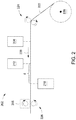
- FIG. 2 is a schematic view of an example printer For example the printer of figure 1 .
- Printer 202 comprises an input unwinder 220, a pair of pinch rollers 224, a first print engine 208, a sensor 212, a second print engine 210, a pair of take-up rollers 226 and an encoder 206.
- the media transport system uses a continuous roll of media 222 mounted onto input spindle 220.
- the printer may use sheets of media instead of a continuous roll of media 222.
- a media path starts at the input spindle 220, goes between the pair of pinch rollers 224, underneath the first print engine 208 and the sensor 212, above the second print engine 210, and then between the pair of take-up rollers.
- the encoder 206 is coupled to the pair of take-up rollers 226 and its rotation is proportional to the distance the media travels between the pair of take-up rollers 226.
- the rate of rotation of the encoder is proportional to the velocity of the media in the media path.
- the media moves in the direction of arrow 228 during printing.
- the direction the media moves during printing is also known as the downstream direction. Therefore the sensor 212 and the second print engine are downstream from the first print engine 208.
- the second print engine 210 is downstream from the sensor by distance d.
- the distance d is equivalent to a given number of encoder counts in encoder 206.
- a printer can be calibrated at a single printing speed to align the duplex image with the simplex image using only the location of the alignment mark by measuring the alignment offset between two patterns printed by the two print engines.
- the alignment offset between the two patterns is caused by two different types of errors: errors due to a delay in time and errors due to a delay in space.
- the time delays have an effect on where the drops land on the paper depending on the media speed, while the space delays have a constant offset on drop placement on media, regardless of the media speed.
- Errors that add a delay in space cause miss-alignments that are independent of the speed of the media.
- One example is the variation in the location of the sensor 212 with respect to the location of the second print engine 210 (i.e. distance d) due to manufacturing tolerances. Different distances d cause a different number of encoder counts between the time the alignment mark is detected and when the simplex image reaches the duplex print engine.
- Another example of an error in space delay is related to when the printheads fire the drops from a particular column of nozzles. The printheads fire the drops for one particular column when the data for the next column is received which is at the next encoder count. That introduces a delay equal to 1 encoder count or 1 column distance on paper (1/600 inches when printing at 600 dpi), regardless of the media speed.
- a time delay is the response time of the sensor.
- the response delay of the TOF sensor is 50 ⁇ s, regardless of the media speed. It takes 50 ⁇ s for the sensor to toggle its output after it has detected the TOP mark. Although that delay is constant and independent of the media speed, during those 50 ⁇ s, the paper advances more or less depending on its speed.
- Another example of a time delay is the drop fly time. The drop fly time is the time it takes for the ink drops to land on the paper once they are ejected.
- the total alignment offset detected by the vision system during a calibration is equivalent to the amount of media that goes by the duplex print engine during the time between when the sensor detects the alignment mark till when the simplex image reaches the duplex print engine.
- the alignment offset is a combination of both the time delays and the space delays. This alignment offset can be expressed by the following formula using the two error types: Where:
- the printer will position the location of the duplex image on the second side of the media using the instantaneous velocity of the media when the alignment mark is detected.
- the duplex image can be aligned with the image on the first side of the media at any given printing speed, including "on-the-ramp” speeds.
- the alignment module will latch the encoder position as well as the instantaneous velocity of the media when the sensor detects the alignment mark.
- the alignment offset O cal can be determined for any given speed, including "on-the-ramp" speeds.
- FIG. 3 is a flow chart for an example alignment calibration process.
- an alignment pattern will be printed on both sides of the media at a first printing/media speed.
- a first offset between the first and second images will be measured. The offset can be measured using an automated vision system or a human operator.
- a second set of alignment patterns will be printed on side A and side B of the media at a second printing/media speed.
- a second offset between the first and second images will be measured
- the time delay error T e and the space delay error d e will be calculated using the first and second offsets and the first and second print speeds.
- the time delay error T e and the space delay error d e can be calculated as follows:
- the first printing/media speed will be a fast printing/media speed (V fast ) and the second printing/media speed will be slow (V slow ).
- the fast printing speed may be the maximum printing speed for the printer and the slow printing speed may be the minimum printing speed for the printer.
- the maximum print speed may be between 3,56 m/s and 5,08 m/s, for example 4,06 m/s (700 and 1,000 feet per minute (fpm), for example 800 fpm).
- the minimum print speed may be between 0,25 m/ s and 1,78 m/s, for example 1,02 m/s (50 and 350 fpm, for example 200 fpm).
- the printer will print at the two different print speeds during the alignment calibration process without bring the printer to a full stop between the two speeds.
- Equation 1 can be used at any print speed to determine the correct alignment offset to use to align the duplex image to the simplex image.
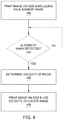
- Figure 4 is a flow chart for printing a duplex image in one example.
- an image, including an alignment mark is printed on side A of the media.
- a check is made to determine if the alignment mark has been detected by the sensor. If the alignment mark has not been detected, flow returns to block 444.
- the alignment mark is detected flow continues at block 446.
- the position of the alignment mark and velocity of the media is determined and latched/stored.
- the image is printed onto side B of the media where the location of the image is based on the velocity of the media.
- equation 1 is used to determine the correct alignment offset for each frame/page when the velocity of the media is constant and when the velocity of the media is changing.
- equation 1 when the print/media speed is a constant, equation 1 will be used one time to determine the correct alignment offset when printing the first frame. The determined alignment offset will then be re-used for each frame as long as the printing/media speed remains constant. When printing "on-the-ramp" a new alignment offset is calculated for each frame/page being printed. Once the target printing speed is reached the same alignment offset can be re-used.
- Figure 5 is a flow chart for printing duplex pages in another example.
- the printer starts accelerating the media.
- a check is made to determine if the media has reached the minimum printing speed. In some examples the printer may be able to print at any speed above zero. In other example the printer may only be able to print once the media has reached a minimum speed, for example 1,02 m/s (200 feet per minute (fpm)).
- the position of the alignment mark and the media velocity are determined.
- a check is made to determine if the current media velocity has changed from the last time it was saved.
- a change in media velocity can be a change of velocity above some threshold velocity.
- the velocity threshold may be in the range between 0.03 m/s and 3 m/s, for example 0,3 m/s (0.1 feet per second (fps) and 10 fps, for example 1 fps). In other examples the velocity threshold may be lower or higher.
- a new alignment offset is calculated, for example using equation 1, using the current media velocity. The new alignment offset and current media velocity/speed are stored. Flow then continues at block 566. When the media velocity has not changed in block 562 flow continues at block 566.
- an image is printed onto side B of the media using the stored alignment offset.
- Figure 6 is a block diagram illustrating a computing device including a processor and a non-transitory, computer readable storage medium to store instructions to print duplex images according to an example.
- the non-transitory, computer readable storage medium 674 may be included in a computing device 670 such as a printer to print duplex images, for example the printer shown in figure 1 .
- the non-transitory, computer readable storage medium 674 may comprise volatile memory, non-volatile memory, and a storage device. In one example the storage medium may be memory in the alignment module shown in figure 1 .
- Examples of non-volatile storage medium include, but are not limited to, electrically erasable programmable read only memory (EEPROM) and read only memory (ROM).
- Examples of volatile memory include, but are not limited to, static random access memory (SRAM), and dynamic random access memory (DRAM).
- Examples of storage devices include, but are not limited to, hard disk drives, compact disc drives, digital versatile disc drives, optical drives, and flash memory devices.
Landscapes
- Ink Jet (AREA)
- Accessory Devices And Overall Control Thereof (AREA)
Claims (11)
- Drucker (102) zum Tintenstrahl- oder Laserdruck, der Folgendes umfasst:ein Medientransportsystem, MTS, (104) zum Bewegen von Medien durch den Drucker (102), wobei das Medientransportsystem einen Codierer (106) und einen Medienweg beinhaltet;eine erste Druckmaschine (108) zum Drucken auf einer ersten Seite des Mediums, wobei die erste Druckmaschine (108) an einer ersten Stelle im Medienweg positioniert ist;eine zweite Druckmaschine (112) zum Drucken auf einer zweiten Seite des Mediums, wobei die zweite Druckmaschine (112) in dem Medienweg in Verarbeitungsrichtung nachgelagert zu der ersten Stelle positioniert ist;einen Sensor (110), der zwischen der ersten und der zweiten Druckmaschine positioniert und positioniert ist, um die erste Seite des Mediums zu betrachten; undein Ausrichtungsmodul (114), das mit dem Sensor, dem Codierer und der ersten und der zweiten Druckmaschine verbunden ist;wobei das Ausrichtungsmodul (114) dazu dient, eine Ausrichtungsmarkierung auf der ersten Seite des Mediums unter Verwendung des Sensors (110) zu erfassen und die Geschwindigkeit des Mediums mit dem Codierer (106), wenn die Ausrichtungsmarkierung erfasst wird, zu bestimmen; undwobei das Ausrichtungsmodul (114) dazu dient, Duplexbilder auf das Medium mit der zweiten Druckmaschine (112) zu drucken, wobei die Stelle der Duplexbilder auf einem Ausrichtungsversatz basiert, wobei der Ausrichtungsversatz unter Verwendung der Geschwindigkeit des Mediums und eines Zeitverzögerungsfehlers T e und eines Raumverzögerungsfehlers d e berechnet wird, wobei das Ausrichtungsmodul (114) den Ausrichtungsversatz nur neu berechnet, wenn sich die Mediengeschwindigkeit um mehr als eine Schwellengeschwindigkeit geändert hat.
- Drucker nach Anspruch 1, wobei der Zeitverzögerungsfehler T e und der Raumverzögerungsfehler d e während eines Ausrichtungskalibrierungsprozesses bestimmt werden.
- Drucker nach Anspruch 2, wobei der Ausrichtungskalibrierungsprozess Folgendes umfasst:Drucken eines ersten Musters auf einer ersten Seite des Mediums und eines zweiten Musters auf der zweiten Seite des Mediums mit einer ersten Druckgeschwindigkeit;Messen eines ersten Versatzes zwischen dem ersten und dem zweiten Muster;Drucken eines ersten Musters auf einer ersten Seite des Mediums und eines zweiten Musters auf der zweiten Seite des Mediums mit einer zweiten Druckgeschwindigkeit, die sich von der ersten Druckgeschwindigkeit unterscheidet;Messen eines zweiten Versatzes zwischen dem ersten und dem zweiten Muster;Bestimmen des Zeitverzögerungsfehlers T e und des Raumverzögerungsfehlers d e unter Verwendung des ersten und des zweiten Versatzes;Speichern des Zeitverzögerungsfehlers T e und des Raumverzögerungsfehlers d e .
- Verfahren zum Tintenstrahl- oder Laserdruck, das Folgendes umfasst:Drucken eines Bildes auf einer ersten Seite des Mediums, einschließlich einer Ausrichtungsmarkierung, auf der sich das Medium auf einem Medienweg bewegt;Erfassen der Ausrichtungsmarkierung auf dem Medium mit einem Sensor (110);wenn die Ausrichtungsmarkierung erfasst wird, Bestimmen einer Geschwindigkeit des Mediums, das sich auf dem Medienweg bewegt;gekennzeichnet durch Berechnen eines Ausrichtungsversatzes basierend auf der Geschwindigkeit des Mediums und eines Zeitverzögerungsfehlers T e und des Raumverzögerungsfehlers d e ; undDrucken eines Bildes auf einer zweiten Seite des Mediums, wobei die Position des zweiten Bildes auf dem Ausrichtungsversatz basiert, wobei der Ausrichtungsversatz nur neu berechnet wird, wenn sich die Mediengeschwindigkeit um mehr als eine Schwellengeschwindigkeit geändert hat.
- Druckverfahren nach Anspruch 4, wobei die Geschwindigkeit des Mediums steigend ist.
- Druckverfahren nach Anspruch 5, wobei die Geschwindigkeit des Mediums abnehmend ist.
- Druckverfahren nach Anspruch 4, wobei der Zeitverzögerungsfehler T e und der Raumverzögerungsfehler d e während eines Ausrichtungskalibrierungsprozesses bestimmt werden und der Ausrichtungskalibrierungsprozess Folgendes umfasst:Drucken eines ersten Musters auf einer ersten Seite des Mediums und eines zweiten Musters auf der zweiten Seite des Mediums mit einer ersten Druckgeschwindigkeit;Messen eines ersten Versatzes zwischen dem ersten und dem zweiten Muster;Drucken eines ersten Musters auf einer ersten Seite des Mediums und eines zweiten Musters auf der zweiten Seite des Mediums mit einer zweiten Druckgeschwindigkeit, die sich von der ersten Druckgeschwindigkeit unterscheidet;Messen eines zweiten Versatzes zwischen dem ersten und dem zweiten Muster;Bestimmen des Zeitverzögerungsfehlers T e und des Raumverzögerungsfehlers d e unter Verwendung des ersten und des zweiten Versatzes;Speichern des Zeitverzögerungsfehlers T e und des Raumverzögerungsfehlers d e .
- Verfahren zum Kalibrieren eines Tintenstrahl- oder Laserdruckers, das Folgendes umfasst:Drucken eines ersten Musters auf einer ersten Seite des Mediums und eines zweiten Musters auf der zweiten Seite des Mediums mit einer ersten Druckgeschwindigkeit;Messen eines ersten Versatzes zwischen dem ersten und dem zweiten Muster;Drucken eines ersten Musters auf einer ersten Seite des Mediums und eines zweiten Musters auf der zweiten Seite des Mediums mit einer zweiten Druckgeschwindigkeit, die sich von der ersten Druckgeschwindigkeit unterscheidet;Messen eines zweiten Versatzes zwischen dem ersten und dem zweiten Muster;Bestimmen eines Zeitverzögerungsfehlers T e und eines Raumverzögerungsfehlers d e zwischen einem Sensor und einem Duplexdruckkopf unter Verwendung des ersten und des zweiten Versatzes;Einstellen der Stelle eines Bildes auf der zweiten Seite des Mediums in Bezug auf ein Bild auf der ersten Seite des Mediums unter Verwendung des Zeitverzögerungsfehlers T e und eines Raumverzögerungsfehlers d e , wobei der Drucker nur neu kalibriert wird, wenn sich die Druckgeschwindigkeit um mehr als eine Schwellengeschwindigkeit geändert hat.
- Verfahren zum Kalibrieren eines Druckers nach Anspruch 8, wobei die erste Druckgeschwindigkeit eine schnelle Druckgeschwindigkeit und die zweite Druckgeschwindigkeit eine langsame Druckgeschwindigkeit ist.
- Verfahren zum Kalibrieren eines Druckers nach Anspruch 8, wobei die erste Druckgeschwindigkeit eine maximale Druckgeschwindigkeit und die zweite Druckgeschwindigkeit eine minimale Druckgeschwindigkeit ist.
- Verfahren zum Kalibrieren eines Druckers nach Anspruch 8, wobei das Medium dazwischen nicht stoppt, wenn die Bilder mit der ersten Geschwindigkeit gedruckt werden und wenn die Bilder mit der zweiten Geschwindigkeit gedruckt werden.
Applications Claiming Priority (1)
| Application Number | Priority Date | Filing Date | Title |
|---|---|---|---|
| PCT/US2014/064711 WO2016073009A1 (en) | 2014-11-09 | 2014-11-09 | Duplex printing |
Publications (3)
| Publication Number | Publication Date |
|---|---|
| EP3215368A1 EP3215368A1 (de) | 2017-09-13 |
| EP3215368A4 EP3215368A4 (de) | 2018-07-11 |
| EP3215368B1 true EP3215368B1 (de) | 2020-05-06 |
Family
ID=55909565
Family Applications (1)
| Application Number | Title | Priority Date | Filing Date |
|---|---|---|---|
| EP14905603.8A Active EP3215368B1 (de) | 2014-11-09 | 2014-11-09 | Duplexdrucken |
Country Status (4)
| Country | Link |
|---|---|
| US (2) | US10201990B2 (de) |
| EP (1) | EP3215368B1 (de) |
| CN (1) | CN107000450B (de) |
| WO (1) | WO2016073009A1 (de) |
Families Citing this family (8)
| Publication number | Priority date | Publication date | Assignee | Title |
|---|---|---|---|---|
| DE102014107223A1 (de) * | 2014-05-22 | 2015-11-26 | Gt+W Gmbh (In Gründung) | Druckverfahren und Druckvorrichtung |
| CN109891330A (zh) * | 2016-07-12 | 2019-06-14 | 海德拉管理有限责任公司 | 具有多个排列式成像器的闭环色彩校准 |
| JP6962128B2 (ja) * | 2017-10-20 | 2021-11-05 | コニカミノルタ株式会社 | 画像形成装置 |
| CN108319339B (zh) * | 2018-01-31 | 2020-04-24 | 京东方科技集团股份有限公司 | 一种显示装置及显示方法 |
| CN110202962B (zh) * | 2019-06-25 | 2021-06-18 | 深圳弘博智能数码设备有限公司 | 一种用于数码印刷机的正背套准检测方法 |
| KR102532509B1 (ko) * | 2021-04-19 | 2023-05-16 | (주)에스티아이 | 디스플레이 제조용 잉크젯 프린터 |
| US12143552B1 (en) | 2023-11-13 | 2024-11-12 | Ricoh Company, Ltd. | Print scaling correction mechanism |
| CN118752919B (zh) * | 2024-08-21 | 2025-01-07 | 东莞永达彩印有限公司 | 一种用于油墨印刷机印刷过程的智能控制方法及系统 |
Family Cites Families (18)
| Publication number | Priority date | Publication date | Assignee | Title |
|---|---|---|---|---|
| KR100464128B1 (ko) * | 1997-08-06 | 2005-06-01 | 세이코 엡슨 가부시키가이샤 | 기록매체처리장치 및 기록매체처리방법 |
| JP3680989B2 (ja) * | 2000-12-22 | 2005-08-10 | リコープリンティングシステムズ株式会社 | 印刷システム |
| JP2005205759A (ja) | 2004-01-23 | 2005-08-04 | Ricoh Printing Systems Ltd | 両面印刷システム |
| US7967407B2 (en) | 2006-02-03 | 2011-06-28 | R.R. Donnelley | Use of a sense mark to control a printing system |
| EP1939005A1 (de) | 2006-12-28 | 2008-07-02 | Agfa Graphics N.V. | Synchronisation des Vorder- und Rückseitendruckes bei doppelseitigen Tintenstrahlrollendrucken |
| US8169657B2 (en) | 2007-05-09 | 2012-05-01 | Xerox Corporation | Registration method using sensed image marks and digital realignment |
| US8753026B2 (en) | 2007-06-29 | 2014-06-17 | R.R. Donnelley & Sons Company | Use of a sense mark to control a printing system |
| US7837290B2 (en) | 2008-07-18 | 2010-11-23 | Xerox Corporation | Continuous web printing system alignment method |
| US7857414B2 (en) * | 2008-11-20 | 2010-12-28 | Xerox Corporation | Printhead registration correction system and method for use with direct marking continuous web printers |
| US8254825B2 (en) | 2009-02-18 | 2012-08-28 | Xerox Corporation | Controlling sheet registration in a digital printing system |
| US9098903B2 (en) | 2009-07-21 | 2015-08-04 | R.R. Donnelley & Sons Company | Systems and methods for detecting alignment errors |
| US8303071B2 (en) | 2010-05-11 | 2012-11-06 | Xerox Corporation | System and method for controlling registration in a continuous feed tandem printer |
| GB2494091B (en) * | 2010-06-24 | 2016-03-16 | Hewlett Packard Development Co | Web press |
| CN102947094B (zh) * | 2010-06-24 | 2014-11-26 | 惠普发展公司,有限责任合伙企业 | 卷筒印刷机和启动印刷的方法 |
| US8491081B2 (en) * | 2011-03-21 | 2013-07-23 | Xerox Corporation | System and method for compensating for roll eccentricity in a printer |
| US20130286072A1 (en) | 2012-04-30 | 2013-10-31 | Randy E. Armbruster | Correcting web skew in a printing system |
| US8733884B2 (en) | 2012-05-31 | 2014-05-27 | Eastman Kodak Company | Detecting stretch or shrink in print media |
| US9010924B2 (en) * | 2012-07-11 | 2015-04-21 | Xerox Corporation | System and method for aligning duplex images using alignment marks |
-
2014
- 2014-11-09 EP EP14905603.8A patent/EP3215368B1/de active Active
- 2014-11-09 US US15/519,799 patent/US10201990B2/en active Active
- 2014-11-09 WO PCT/US2014/064711 patent/WO2016073009A1/en not_active Ceased
- 2014-11-09 CN CN201480082843.9A patent/CN107000450B/zh not_active Expired - Fee Related
-
2018
- 2018-10-29 US US16/174,038 patent/US10525742B2/en active Active
Non-Patent Citations (1)
| Title |
|---|
| None * |
Also Published As
| Publication number | Publication date |
|---|---|
| CN107000450B (zh) | 2019-02-19 |
| US20190061383A1 (en) | 2019-02-28 |
| US10201990B2 (en) | 2019-02-12 |
| CN107000450A (zh) | 2017-08-01 |
| EP3215368A4 (de) | 2018-07-11 |
| US10525742B2 (en) | 2020-01-07 |
| EP3215368A1 (de) | 2017-09-13 |
| US20170259588A1 (en) | 2017-09-14 |
| WO2016073009A1 (en) | 2016-05-12 |
Similar Documents
| Publication | Publication Date | Title |
|---|---|---|
| US10525742B2 (en) | Duplex printing | |
| JP5311807B2 (ja) | 記録装置 | |
| US8075086B2 (en) | Paper skew detection system | |
| US10343433B2 (en) | Skew sensor calibration | |
| US8757758B2 (en) | Multiple sided media pattern registration system | |
| JP6417858B2 (ja) | 記録装置及び記録装置の制御方法 | |
| US8919770B2 (en) | System and method for identification of media sheet size | |
| US8500234B2 (en) | Registering patterns on multiple media sides | |
| US8662623B2 (en) | Printing registered patterns on multiple media sides | |
| JP6390958B2 (ja) | 記録手段吐出位置調整装置及び画像形成装置 | |
| EP3912820B1 (de) | Ausstossvorrichtung und verfahren zur berechnung der ausstossgeschwindigkeit | |
| US8632153B2 (en) | Printing system having multiple sided pattern registration | |
| JP4882551B2 (ja) | 液滴吐出装置 | |
| JP5239992B2 (ja) | 記録装置における搬送誤差補正方法 | |
| US8727496B2 (en) | Printing | |
| US7387357B2 (en) | Calibration method for printing apparatus | |
| US9511603B2 (en) | Method for printing image planes on substrate | |
| WO2022203691A1 (en) | Printer alignment calibration | |
| US20230043405A1 (en) | Printing upon web media with tractor-feed holes | |
| JP2003276906A (ja) | プリンタ及びプリンタの制御方法 | |
| JP2014004751A (ja) | 印刷装置、印刷装置の制御方法 | |
| JP6900778B2 (ja) | 記録装置 | |
| JP5656445B2 (ja) | 記録装置および記録方法 | |
| JP2005059425A (ja) | インクジェット記録装置 |
Legal Events
| Date | Code | Title | Description |
|---|---|---|---|
| STAA | Information on the status of an ep patent application or granted ep patent |
Free format text: STATUS: THE INTERNATIONAL PUBLICATION HAS BEEN MADE |
|
| PUAI | Public reference made under article 153(3) epc to a published international application that has entered the european phase |
Free format text: ORIGINAL CODE: 0009012 |
|
| STAA | Information on the status of an ep patent application or granted ep patent |
Free format text: STATUS: REQUEST FOR EXAMINATION WAS MADE |
|
| 17P | Request for examination filed |
Effective date: 20170425 |
|
| AK | Designated contracting states |
Kind code of ref document: A1 Designated state(s): AL AT BE BG CH CY CZ DE DK EE ES FI FR GB GR HR HU IE IS IT LI LT LU LV MC MK MT NL NO PL PT RO RS SE SI SK SM TR |
|
| AX | Request for extension of the european patent |
Extension state: BA ME |
|
| DAX | Request for extension of the european patent (deleted) | ||
| A4 | Supplementary search report drawn up and despatched |
Effective date: 20180611 |
|
| RIC1 | Information provided on ipc code assigned before grant |
Ipc: B41J 11/46 20060101ALI20180605BHEP Ipc: B41J 3/60 20060101AFI20180605BHEP |
|
| RAP1 | Party data changed (applicant data changed or rights of an application transferred) |
Owner name: HEWLETT-PACKARD DEVELOPMENT COMPANY, L.P. |
|
| GRAP | Despatch of communication of intention to grant a patent |
Free format text: ORIGINAL CODE: EPIDOSNIGR1 |
|
| STAA | Information on the status of an ep patent application or granted ep patent |
Free format text: STATUS: GRANT OF PATENT IS INTENDED |
|
| RIC1 | Information provided on ipc code assigned before grant |
Ipc: B41J 3/60 20060101AFI20191219BHEP Ipc: B41J 11/46 20060101ALI20191219BHEP |
|
| INTG | Intention to grant announced |
Effective date: 20200117 |
|
| GRAS | Grant fee paid |
Free format text: ORIGINAL CODE: EPIDOSNIGR3 |
|
| GRAL | Information related to payment of fee for publishing/printing deleted |
Free format text: ORIGINAL CODE: EPIDOSDIGR3 |
|
| GRAS | Grant fee paid |
Free format text: ORIGINAL CODE: EPIDOSNIGR3 |
|
| GRAA | (expected) grant |
Free format text: ORIGINAL CODE: 0009210 |
|
| STAA | Information on the status of an ep patent application or granted ep patent |
Free format text: STATUS: THE PATENT HAS BEEN GRANTED |
|
| AK | Designated contracting states |
Kind code of ref document: B1 Designated state(s): AL AT BE BG CH CY CZ DE DK EE ES FI FR GB GR HR HU IE IS IT LI LT LU LV MC MK MT NL NO PL PT RO RS SE SI SK SM TR |
|
| REG | Reference to a national code |
Ref country code: GB Ref legal event code: FG4D |
|
| REG | Reference to a national code |
Ref country code: CH Ref legal event code: EP Ref country code: AT Ref legal event code: REF Ref document number: 1266157 Country of ref document: AT Kind code of ref document: T Effective date: 20200515 |
|
| REG | Reference to a national code |
Ref country code: DE Ref legal event code: R096 Ref document number: 602014065316 Country of ref document: DE |
|
| REG | Reference to a national code |
Ref country code: IE Ref legal event code: FG4D |
|
| REG | Reference to a national code |
Ref country code: LT Ref legal event code: MG4D |
|
| REG | Reference to a national code |
Ref country code: NL Ref legal event code: MP Effective date: 20200506 |
|
| PG25 | Lapsed in a contracting state [announced via postgrant information from national office to epo] |
Ref country code: SE Free format text: LAPSE BECAUSE OF FAILURE TO SUBMIT A TRANSLATION OF THE DESCRIPTION OR TO PAY THE FEE WITHIN THE PRESCRIBED TIME-LIMIT Effective date: 20200506 Ref country code: LT Free format text: LAPSE BECAUSE OF FAILURE TO SUBMIT A TRANSLATION OF THE DESCRIPTION OR TO PAY THE FEE WITHIN THE PRESCRIBED TIME-LIMIT Effective date: 20200506 Ref country code: PT Free format text: LAPSE BECAUSE OF FAILURE TO SUBMIT A TRANSLATION OF THE DESCRIPTION OR TO PAY THE FEE WITHIN THE PRESCRIBED TIME-LIMIT Effective date: 20200907 Ref country code: IS Free format text: LAPSE BECAUSE OF FAILURE TO SUBMIT A TRANSLATION OF THE DESCRIPTION OR TO PAY THE FEE WITHIN THE PRESCRIBED TIME-LIMIT Effective date: 20200906 Ref country code: FI Free format text: LAPSE BECAUSE OF FAILURE TO SUBMIT A TRANSLATION OF THE DESCRIPTION OR TO PAY THE FEE WITHIN THE PRESCRIBED TIME-LIMIT Effective date: 20200506 Ref country code: NO Free format text: LAPSE BECAUSE OF FAILURE TO SUBMIT A TRANSLATION OF THE DESCRIPTION OR TO PAY THE FEE WITHIN THE PRESCRIBED TIME-LIMIT Effective date: 20200806 Ref country code: GR Free format text: LAPSE BECAUSE OF FAILURE TO SUBMIT A TRANSLATION OF THE DESCRIPTION OR TO PAY THE FEE WITHIN THE PRESCRIBED TIME-LIMIT Effective date: 20200807 |
|
| PG25 | Lapsed in a contracting state [announced via postgrant information from national office to epo] |
Ref country code: LV Free format text: LAPSE BECAUSE OF FAILURE TO SUBMIT A TRANSLATION OF THE DESCRIPTION OR TO PAY THE FEE WITHIN THE PRESCRIBED TIME-LIMIT Effective date: 20200506 Ref country code: RS Free format text: LAPSE BECAUSE OF FAILURE TO SUBMIT A TRANSLATION OF THE DESCRIPTION OR TO PAY THE FEE WITHIN THE PRESCRIBED TIME-LIMIT Effective date: 20200506 Ref country code: BG Free format text: LAPSE BECAUSE OF FAILURE TO SUBMIT A TRANSLATION OF THE DESCRIPTION OR TO PAY THE FEE WITHIN THE PRESCRIBED TIME-LIMIT Effective date: 20200806 Ref country code: HR Free format text: LAPSE BECAUSE OF FAILURE TO SUBMIT A TRANSLATION OF THE DESCRIPTION OR TO PAY THE FEE WITHIN THE PRESCRIBED TIME-LIMIT Effective date: 20200506 |
|
| REG | Reference to a national code |
Ref country code: AT Ref legal event code: MK05 Ref document number: 1266157 Country of ref document: AT Kind code of ref document: T Effective date: 20200506 |
|
| PG25 | Lapsed in a contracting state [announced via postgrant information from national office to epo] |
Ref country code: NL Free format text: LAPSE BECAUSE OF FAILURE TO SUBMIT A TRANSLATION OF THE DESCRIPTION OR TO PAY THE FEE WITHIN THE PRESCRIBED TIME-LIMIT Effective date: 20200506 Ref country code: AL Free format text: LAPSE BECAUSE OF FAILURE TO SUBMIT A TRANSLATION OF THE DESCRIPTION OR TO PAY THE FEE WITHIN THE PRESCRIBED TIME-LIMIT Effective date: 20200506 |
|
| PG25 | Lapsed in a contracting state [announced via postgrant information from national office to epo] |
Ref country code: CZ Free format text: LAPSE BECAUSE OF FAILURE TO SUBMIT A TRANSLATION OF THE DESCRIPTION OR TO PAY THE FEE WITHIN THE PRESCRIBED TIME-LIMIT Effective date: 20200506 Ref country code: IT Free format text: LAPSE BECAUSE OF FAILURE TO SUBMIT A TRANSLATION OF THE DESCRIPTION OR TO PAY THE FEE WITHIN THE PRESCRIBED TIME-LIMIT Effective date: 20200506 Ref country code: RO Free format text: LAPSE BECAUSE OF FAILURE TO SUBMIT A TRANSLATION OF THE DESCRIPTION OR TO PAY THE FEE WITHIN THE PRESCRIBED TIME-LIMIT Effective date: 20200506 Ref country code: SM Free format text: LAPSE BECAUSE OF FAILURE TO SUBMIT A TRANSLATION OF THE DESCRIPTION OR TO PAY THE FEE WITHIN THE PRESCRIBED TIME-LIMIT Effective date: 20200506 Ref country code: EE Free format text: LAPSE BECAUSE OF FAILURE TO SUBMIT A TRANSLATION OF THE DESCRIPTION OR TO PAY THE FEE WITHIN THE PRESCRIBED TIME-LIMIT Effective date: 20200506 Ref country code: AT Free format text: LAPSE BECAUSE OF FAILURE TO SUBMIT A TRANSLATION OF THE DESCRIPTION OR TO PAY THE FEE WITHIN THE PRESCRIBED TIME-LIMIT Effective date: 20200506 Ref country code: DK Free format text: LAPSE BECAUSE OF FAILURE TO SUBMIT A TRANSLATION OF THE DESCRIPTION OR TO PAY THE FEE WITHIN THE PRESCRIBED TIME-LIMIT Effective date: 20200506 Ref country code: ES Free format text: LAPSE BECAUSE OF FAILURE TO SUBMIT A TRANSLATION OF THE DESCRIPTION OR TO PAY THE FEE WITHIN THE PRESCRIBED TIME-LIMIT Effective date: 20200506 |
|
| PGFP | Annual fee paid to national office [announced via postgrant information from national office to epo] |
Ref country code: GB Payment date: 20201021 Year of fee payment: 7 Ref country code: FR Payment date: 20201021 Year of fee payment: 7 Ref country code: DE Payment date: 20201020 Year of fee payment: 7 |
|
| REG | Reference to a national code |
Ref country code: DE Ref legal event code: R097 Ref document number: 602014065316 Country of ref document: DE |
|
| PG25 | Lapsed in a contracting state [announced via postgrant information from national office to epo] |
Ref country code: SK Free format text: LAPSE BECAUSE OF FAILURE TO SUBMIT A TRANSLATION OF THE DESCRIPTION OR TO PAY THE FEE WITHIN THE PRESCRIBED TIME-LIMIT Effective date: 20200506 Ref country code: PL Free format text: LAPSE BECAUSE OF FAILURE TO SUBMIT A TRANSLATION OF THE DESCRIPTION OR TO PAY THE FEE WITHIN THE PRESCRIBED TIME-LIMIT Effective date: 20200506 |
|
| PLBE | No opposition filed within time limit |
Free format text: ORIGINAL CODE: 0009261 |
|
| STAA | Information on the status of an ep patent application or granted ep patent |
Free format text: STATUS: NO OPPOSITION FILED WITHIN TIME LIMIT |
|
| 26N | No opposition filed |
Effective date: 20210209 |
|
| PG25 | Lapsed in a contracting state [announced via postgrant information from national office to epo] |
Ref country code: SI Free format text: LAPSE BECAUSE OF FAILURE TO SUBMIT A TRANSLATION OF THE DESCRIPTION OR TO PAY THE FEE WITHIN THE PRESCRIBED TIME-LIMIT Effective date: 20200506 |
|
| PG25 | Lapsed in a contracting state [announced via postgrant information from national office to epo] |
Ref country code: MC Free format text: LAPSE BECAUSE OF FAILURE TO SUBMIT A TRANSLATION OF THE DESCRIPTION OR TO PAY THE FEE WITHIN THE PRESCRIBED TIME-LIMIT Effective date: 20200506 |
|
| REG | Reference to a national code |
Ref country code: CH Ref legal event code: PL |
|
| PG25 | Lapsed in a contracting state [announced via postgrant information from national office to epo] |
Ref country code: LU Free format text: LAPSE BECAUSE OF NON-PAYMENT OF DUE FEES Effective date: 20201109 |
|
| REG | Reference to a national code |
Ref country code: BE Ref legal event code: MM Effective date: 20201130 |
|
| PG25 | Lapsed in a contracting state [announced via postgrant information from national office to epo] |
Ref country code: CH Free format text: LAPSE BECAUSE OF NON-PAYMENT OF DUE FEES Effective date: 20201130 Ref country code: LI Free format text: LAPSE BECAUSE OF NON-PAYMENT OF DUE FEES Effective date: 20201130 |
|
| PG25 | Lapsed in a contracting state [announced via postgrant information from national office to epo] |
Ref country code: IE Free format text: LAPSE BECAUSE OF NON-PAYMENT OF DUE FEES Effective date: 20201109 |
|
| PG25 | Lapsed in a contracting state [announced via postgrant information from national office to epo] |
Ref country code: TR Free format text: LAPSE BECAUSE OF FAILURE TO SUBMIT A TRANSLATION OF THE DESCRIPTION OR TO PAY THE FEE WITHIN THE PRESCRIBED TIME-LIMIT Effective date: 20200506 Ref country code: MT Free format text: LAPSE BECAUSE OF FAILURE TO SUBMIT A TRANSLATION OF THE DESCRIPTION OR TO PAY THE FEE WITHIN THE PRESCRIBED TIME-LIMIT Effective date: 20200506 Ref country code: CY Free format text: LAPSE BECAUSE OF FAILURE TO SUBMIT A TRANSLATION OF THE DESCRIPTION OR TO PAY THE FEE WITHIN THE PRESCRIBED TIME-LIMIT Effective date: 20200506 |
|
| REG | Reference to a national code |
Ref country code: DE Ref legal event code: R119 Ref document number: 602014065316 Country of ref document: DE |
|
| PG25 | Lapsed in a contracting state [announced via postgrant information from national office to epo] |
Ref country code: MK Free format text: LAPSE BECAUSE OF FAILURE TO SUBMIT A TRANSLATION OF THE DESCRIPTION OR TO PAY THE FEE WITHIN THE PRESCRIBED TIME-LIMIT Effective date: 20200506 |
|
| GBPC | Gb: european patent ceased through non-payment of renewal fee |
Effective date: 20211109 |
|
| PG25 | Lapsed in a contracting state [announced via postgrant information from national office to epo] |
Ref country code: BE Free format text: LAPSE BECAUSE OF NON-PAYMENT OF DUE FEES Effective date: 20201130 |
|
| PG25 | Lapsed in a contracting state [announced via postgrant information from national office to epo] |
Ref country code: GB Free format text: LAPSE BECAUSE OF NON-PAYMENT OF DUE FEES Effective date: 20211109 Ref country code: DE Free format text: LAPSE BECAUSE OF NON-PAYMENT OF DUE FEES Effective date: 20220601 |
|
| PG25 | Lapsed in a contracting state [announced via postgrant information from national office to epo] |
Ref country code: FR Free format text: LAPSE BECAUSE OF NON-PAYMENT OF DUE FEES Effective date: 20211130 |