EP3215449B1 - Ascenseur équipé d'un dispositif de freinage - Google Patents
Ascenseur équipé d'un dispositif de freinage Download PDFInfo
- Publication number
- EP3215449B1 EP3215449B1 EP15787539.4A EP15787539A EP3215449B1 EP 3215449 B1 EP3215449 B1 EP 3215449B1 EP 15787539 A EP15787539 A EP 15787539A EP 3215449 B1 EP3215449 B1 EP 3215449B1
- Authority
- EP
- European Patent Office
- Prior art keywords
- braking
- path
- brake
- force
- brake force
- Prior art date
- Legal status (The legal status is an assumption and is not a legal conclusion. Google has not performed a legal analysis and makes no representation as to the accuracy of the status listed.)
- Active
Links
Images




Classifications
-
- B—PERFORMING OPERATIONS; TRANSPORTING
- B66—HOISTING; LIFTING; HAULING
- B66B—ELEVATORS; ESCALATORS OR MOVING WALKWAYS
- B66B5/00—Applications of checking, fault-correcting, or safety devices in elevators
- B66B5/02—Applications of checking, fault-correcting, or safety devices in elevators responsive to abnormal operating conditions
- B66B5/16—Braking or catch devices operating between cars, cages, or skips and fixed guide elements or surfaces in hoistway or well
- B66B5/18—Braking or catch devices operating between cars, cages, or skips and fixed guide elements or surfaces in hoistway or well and applying frictional retarding forces
- B66B5/22—Braking or catch devices operating between cars, cages, or skips and fixed guide elements or surfaces in hoistway or well and applying frictional retarding forces by means of linearly-movable wedges
-
- B—PERFORMING OPERATIONS; TRANSPORTING
- B66—HOISTING; LIFTING; HAULING
- B66B—ELEVATORS; ESCALATORS OR MOVING WALKWAYS
- B66B5/00—Applications of checking, fault-correcting, or safety devices in elevators
- B66B5/02—Applications of checking, fault-correcting, or safety devices in elevators responsive to abnormal operating conditions
- B66B5/16—Braking or catch devices operating between cars, cages, or skips and fixed guide elements or surfaces in hoistway or well
- B66B5/18—Braking or catch devices operating between cars, cages, or skips and fixed guide elements or surfaces in hoistway or well and applying frictional retarding forces
-
- B—PERFORMING OPERATIONS; TRANSPORTING
- B66—HOISTING; LIFTING; HAULING
- B66B—ELEVATORS; ESCALATORS OR MOVING WALKWAYS
- B66B5/00—Applications of checking, fault-correcting, or safety devices in elevators
- B66B5/02—Applications of checking, fault-correcting, or safety devices in elevators responsive to abnormal operating conditions
- B66B5/16—Braking or catch devices operating between cars, cages, or skips and fixed guide elements or surfaces in hoistway or well
- B66B5/18—Braking or catch devices operating between cars, cages, or skips and fixed guide elements or surfaces in hoistway or well and applying frictional retarding forces
- B66B5/24—Braking or catch devices operating between cars, cages, or skips and fixed guide elements or surfaces in hoistway or well and applying frictional retarding forces by acting on guide ropes or cables
-
- B—PERFORMING OPERATIONS; TRANSPORTING
- B66—HOISTING; LIFTING; HAULING
- B66D—CAPSTANS; WINCHES; TACKLES, e.g. PULLEY BLOCKS; HOISTS
- B66D1/00—Rope, cable, or chain winding mechanisms; Capstans
- B66D1/02—Driving gear
- B66D1/04—Driving gear manually operated
- B66D1/06—Safety cranks for preventing unwanted crank rotation and subsequent lowering of the loads
-
- B—PERFORMING OPERATIONS; TRANSPORTING
- B66—HOISTING; LIFTING; HAULING
- B66D—CAPSTANS; WINCHES; TACKLES, e.g. PULLEY BLOCKS; HOISTS
- B66D1/00—Rope, cable, or chain winding mechanisms; Capstans
- B66D1/28—Other constructional details
- B66D1/40—Control devices
- B66D1/48—Control devices automatic
- B66D1/485—Control devices automatic electrical
-
- B—PERFORMING OPERATIONS; TRANSPORTING
- B66—HOISTING; LIFTING; HAULING
- B66D—CAPSTANS; WINCHES; TACKLES, e.g. PULLEY BLOCKS; HOISTS
- B66D1/00—Rope, cable, or chain winding mechanisms; Capstans
- B66D1/54—Safety gear
- B66D1/58—Safety gear responsive to excess of load
-
- B—PERFORMING OPERATIONS; TRANSPORTING
- B66—HOISTING; LIFTING; HAULING
- B66D—CAPSTANS; WINCHES; TACKLES, e.g. PULLEY BLOCKS; HOISTS
- B66D5/00—Braking or detent devices characterised by application to lifting or hoisting gear, e.g. for controlling the lowering of loads
- B66D5/02—Crane, lift hoist, or winch brakes operating on drums, barrels, or ropes
- B66D5/24—Operating devices
- B66D5/26—Operating devices pneumatic or hydraulic
Definitions
- the present invention relates to an elevator with a braking device, in particular a service brake or a safety gear.
- Such service brakes can, for example, act on a traction sheave of the elevator or be arranged on the car of the elevator and act on the guide rails.
- a braking device preferably generates a constant braking force, which is usually set so that the car loaded with a nominal load is braked with a deceleration of 0.8 to 1 g for safety gears and 0.3 to 0.5 g for service brakes.
- the braking deceleration of the braking device can be limited by adjustment, for example by control or regulation. Since the braking deceleration of the car depends on the weight of the car and the load of the car, the braking force should be adjusted to the load of the car. Such a braking device must still ensure the required level of safety despite increasing complexity.
- a safety requirement is that the braking device works according to the closed-circuit principle (active when switched on). However, the quiescent current principle requires constant Energy feed into an actuator of the braking device. This leads to increased energy consumption by the braking device.
- the brake pad has another decisive influence on the braking force, in particular the coefficient of friction between the brake pad and the guide rail or the traction sheave.
- a change in the coefficient of friction has a direct effect on the braking force and the resulting deceleration. If a braking force correction due to a change in the coefficient of friction is not provided, the result is that the braking force either increases and the car is decelerated more, or the braking force decreases if, for example, there is oil on the guide rail and the car then does not move Standstill comes.
- braking devices in particular brake pads, which are often used in a service brake, are subject to wear.
- a braking device on the car can have two braking units, each of which acts on one of two guide rails.
- the two braking units of the braking device are rigidly (forcibly) connected to one another via a shaft. This means that the same braking forces initially act on guide rails that are arranged on both sides of the car. Due to tolerances, the nature of the guide rails or different levels of contamination, however, due to the wear processes mentioned above, different braking forces can act on both sides of the car and put additional strain on the car due to the resulting torque.
- a braking device for braking a car of an elevator system which has a pawl that can be adjusted between two operating positions.
- the pawl In the first operating position, the pawl is connected to a brake module in such a way that a release force is transmitted from the pawl to the brake module.
- the width of the air gap between the brake module and the device In the first operating position, the width of the air gap between the brake module and the device can be adjusted by regulating the release force in order to adjust the braking force.
- the car is braked emergency by separating the pawl from the brake module.
- the present invention relates to an elevator according to claim 1.
- Advantageous refinements are the subject of the subclaims and the following description.
- the elevator according to the invention has a braking device, in particular a service brake and/or safety gear, wherein the braking device is designed to provide a variable braking force from a minimum braking force to a maximum braking force.
- a first energy storage device is used to provide the maximum Braking force and a second energy storage for providing an adjustable counterforce directed opposite to the maximum braking force are provided.
- the variable braking force is the difference between the maximum braking force and the adjustable counterforce.
- the invention is based on the knowledge that by subtractively superimposing the maximum braking force and the adjustable counterforce provided, a braking force of adjustable magnitude and thus variable braking force can be provided in a particularly simple manner.
- a braking device with a simple structure is thus provided, with which a variable braking force can be provided during normal operation and a maximum braking force in an emergency.
- the first energy storage device has a compression spring for providing the maximum braking force. This provides a braking device with a particularly simple structure.
- the second energy storage device has a counterspring for providing the adjustable counterforce. This also provides a braking device with a particularly simple structure.
- an adjusting element is provided to cooperate with the second energy storage device in order to adjust the adjustable counterforce.
- the size of the adjustable counterforce can be adjusted in normal operation with the adjusting element, while in an emergency the adjusting element is inactive and the maximum braking force is provided.
- the adjusting element has an actuator for charging and discharging the second energy storage.
- the second energy storage e.g. the counterspring
- the second energy storage can be charged with braking energy by tensioning and discharged by relaxing. This allows the height of the adjustable counterforce to be adjusted.
- This also provides a braking device with a particularly simple structure.
- the actuator of the adjusting element is designed as a hollow shaft drive. This provides a braking device with particularly compact dimensions that takes up particularly little space.
- a first trigger path and a second trigger path are provided for triggering the braking device.
- the braking device When the first trigger path is active, the braking device provides the variable braking force, and when the second trigger path is active, the braking device provides the maximum braking force.
- a trigger path is understood to mean a signal path of a control signal for activating the braking device, which passes through several components of the braking device.
- the first and second trigger paths run parallel to one another at least in sections and thus form two alternatives for triggering the braking device.
- a trigger element is provided for unlocking the second energy storage when the second trigger path is active, with the second energy storage being decoupled from the first energy storage after the second energy storage has been activated.
- the adjustable counterforce is decoupled from the energy storage device.
- a clutch is provided as a trigger element.
- the coupling can provide a force-transmitting connection via positive or frictional connection.
- the clutch makes it possible to change from the first triggering path to the second triggering path in a particularly simple manner and at the same time enable the displacement-force converter to be activated.
- the clutch therefore fulfills a dual function. This simplifies the structure of the braking device.
- the clutch can be designed such that energy is only required to open the clutch. This reduces the energy requirement again.
- a controller for adjusting the variable braking force is assigned to the first trigger path.
- a braking force corresponding to the loading condition and/or wear condition of the braking device of the car can thus be provided. For example, it can be ensured that the deceleration does not exceed a defined value, for example 0.8 to 1 g, even with a car that is only slightly loaded. This minimizes the risk of injury to elevator passengers during a braking process of the car. In addition, the state of wear can be taken into account during operation become. Furthermore, with a braking device acting on both sides of the car, the mechanical load on the car can be reduced by a torque.
- the first trigger path is designed to work according to the working current principle.
- the working current principle is understood to mean that the braking device is opened or ventilated when a brake control signal, such as an electrical current or an electrical voltage, is present that is not equal to zero.
- the first trigger path which provides the braking force of the desired magnitude, can therefore be designed to be particularly energy-efficient. Therefore, the braking device can provide a variable braking force that can be adjusted by control or regulation with energy-efficient operation.
- the second trigger path is designed to work according to the closed-circuit principle.
- the quiescent current principle means that the braking device is opened or ventilated when a brake control signal, such as an electrical current or an electrical voltage, is equal to zero.
- the second trigger path which provides the maximum braking force, can therefore meet safety-relevant requirements during energy-efficient operation.
- the braking device has a self-locking gear for adjusting the variable braking force, which is assigned to the first trigger path.
- the self-locking gear can be, for example, a spindle gear. Additional energy is therefore only necessary to set the variable braking force, but not to maintain a set braking force value. The energy requirement of the braking device is thus further reduced.
- Figure 1 is shown schematically as a preferred embodiment of an elevator according to the invention and is designated overall by the reference number 2.
- the elevator 2 has a car 4 for transporting people and/or loads, which can be moved in or against the direction of gravity g along two mutually parallel guide rails 6a, 6b in an elevator shaft. Deviating from the present embodiment, however, the car 4 can also be moved along a single guide rail, for example.
- a drive 50 is provided, which in the present embodiment is designed as a traction sheave drive.
- the car 4 can have a cabin and a catch frame (both not shown).
- the drive 50 has a suspension element 8, such as suspension cables, which is attached to the top of the car 4.
- the suspension element 8 runs on a traction sheave 12, which can be driven by a motor (not shown) in order to move the car 4.
- a counterweight 10 is attached, which reduces the effort needed to move the car 4 by balancing the weight.
- another drive can also be used, such as a linear drive.
- a braking device 14 is provided, which in the present embodiment is designed as a service brake and/or safety gear and is arranged on both sides of the car 4, so that the braking device 14 acts on both guide rails 6a and 6b.
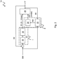
- the Figure 2 shows the braking device 14 in detail.
- the braking device 14 comprises a controller 16, an adjusting element 18, a brake unit 20, a comparison unit 22 and an emergency trigger 24.
- the braking device 14 is electrically ventilated according to the present embodiment.
- the braking device can also be ventilated hydraulically or pneumatically.
- the braking device 14 is supplied with a setpoint SW for the deceleration depending on the degree of loading of the car 4.
- the setpoint SW is compared with a measured actual value IW of the delay, and the difference, ie the control deviation, is fed to the controller 16, which determines a manipulated variable ST based on this difference between the setpoint SW and the actual value IW.
- the manipulated variable ST is supplied to the adjusting element 18, which transmits a first control signal S1 to the brake unit 20 for providing a variable braking force V between a minimum braking force and a maximum braking force Vmax.
- the value of the minimum braking force can also be zero.
- a first triggering path I of the braking device 14 is active, wherein according to the present embodiment, the first triggering path I includes the controller 16 and the adjusting element 18. The control deviation is thus supplied as an input to the first triggering path I and the first control signal S1 controls the brake unit 20 as an output.
- a second trigger path II is provided.
- the comparison unit 22 compares the difference between the setpoint SW and the actual value IW with a predetermined limit value.
- the comparison unit 22 can have a comparator. If the difference exceeds the specified limit value, it is concluded that the car 4 is not being overspeeded.
- An emergency trigger signal NA is then generated by the comparison unit 22 and transmitted to the emergency trigger 24.
- the emergency trigger generates a second control signal S2 that is transmitted to the brake unit 20 to provide the maximum braking force Vmax. Therefore, in the event of a fault, a second trigger path II is active, with the second trigger path II having the comparison unit 22 and the emergency trigger 24 according to the present embodiment.
- the difference between the setpoint SW and the actual value IW is thus supplied as an input to the second trigger path II and the second control signal S2 controls the brake unit 20 as an output.
- the braking device 14 In order to ensure reliable operation of the braking device 14, for example in the event of an interruption in the energy supply to the elevator 2, the braking device 14 has a buffer battery (not shown) which supplies components of the braking device 14, such as the comparison unit 22, with electrical energy.
- the brake unit 20 can be controlled in normal operation via the first trigger path I and in the event of a fault via the second trigger path II in order to provide a braking force.
- the variable braking force V according to the present embodiment a regulated braking force, is provided via the first triggering path I, while the maximum braking force Vmax is provided via the second triggering path II.
- the first trigger path I is therefore not safety-relevant, while the second trigger path II is safety-relevant. This means that only the components of the second trigger path II need to be designed and tested in a safety-relevant manner.
- control of the variable braking force V can also be provided.
- the Figure 3 shows the structure of the adjusting element 18 and the brake unit 20 of the braking device 14 in detail.
- the adjusting element 18 has an actuator 26 and a gear 28 connected to the actuator 26 on the input side.
- the actuator 26 can be an electric motor.
- the actuator can also be a hydraulic or pneumatic cylinder.
- the gear 28 can be a self-locking gear, such as a spindle gear.
- a displacement-force converter 30 of the brake unit 20 is connected to the transmission 28 on the output side.
- the brake unit 20 also has a clutch 32, a first energy storage 34 and a brake 36.
- the path-force converter 30 may have an elastic element, such as a spring, that converts a change in path into a change in force.
- the change in path is provided by the adjusting element 18 with the actuator 26 and the gear 28.
- a self-locking design of the gear 28 means that the elastic element does not relax when the adjusting element 18 is deactivated, for example due to an interruption in the energy supply to the elevator 2, but rather the elastic element retains its shape.
- the clutch 32 decouples the adjusting element 18 from the displacement-force converter 30 and, as will be described, releases braking energy.
- the first energy storage 34 provides the maximum braking force Vmax.
- the brake 36 provides the variable braking force V or the maximum braking force Vmax, depending on whether it is triggered via the first triggering path I or the second triggering path II.
- the Figure 4 shows further details of the displacement-force converter 30, the first energy storage 34 and the brake 36 of the braking device 2.
- a second energy storage 48 is assigned to the displacement-force converter 30.
- the second energy storage is a counterspring.
- the first energy storage device 34 has a compression spring 46.
- the brake 36 has two brake pads 38a, 38b, which engage on both sides of the guide rail 6a and 6b.
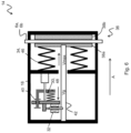
- the Figure 5 shows schematically a section through a first embodiment of the braking device 14 with the brake 36 in the open state.
- the first energy storage 34 is connected at its first end to the brake pad 38a in a force-transmitting manner, while the second end of the braking energy storage 34 is connected to the brake housing 44 in a force-transmitting manner. Therefore, the braking device 14 is mounted floating on the car 4. A second end of the adjusting element 18 is connected to a first end of the displacement-force converter 30 in a force-transmitting manner.
- a second end of the displacement-force converter 30 is connected to a first end of the coupling 32 in a force-transmitting manner.
- the second end of the clutch 32 is in engagement with a release shaft 42 of the braking device 14, which in turn is connected at its front end to the brake pad 38a.
- a stop device 40 is arranged parallel to the displacement-force converter 30, which limits a movement of the clutch 32 with respect to the adjusting element 18, caused by tensioning or relaxing the displacement-force converter 30.
- the first energy storage 34 provides the maximum braking force Vmax, while the second energy storage 48 provides the adjustable counterforce Vg, which reduces the maximum braking force Vmax.
- the adjustable counterforce Vg can assume values from the minimum braking force to the maximum braking force Vmax, whereby the minimum braking force can also be zero. The maximum braking force Vmax and the adjustable counterforce Vg are thus subtractively superimposed.
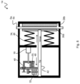
- the Figure 6 shows that to adjust the variable braking force V, for example according to the comparison of the setpoint SW and the actual value IW, the adjusting element 18 can be moved by the actuator 26 and the gear 28 along the direction of extension of the trigger shaft 42 after the brake pads 38a, 38b in System with the guide rail 6a, 6b were brought.
- the first trigger path I is active here.
- the adjusting element 18 Due to the active clutch 32, which is in engagement with the release shaft 42, the adjusting element 18 is moved in the direction of arrow A, which causes the counterspring to relax by discharging the second energy storage 48. This change in path results in the counterspring of the second energy storage 48 providing a reduced, adjustable counterforce Vg, so that the effective variable braking force V increases. If, on the other hand, the adjusting element 18 is moved counter to the direction of arrow A, this causes the counterspring to be tensioned by charging the second energy storage device 48. This change in path results in the counterspring of the second energy storage device 48 providing an increased adjustable counterforce Vg, so that the acting variable Braking force V reduced.
- the Figure 7 shows that the movement of the adjusting element 18 in the direction of arrow A is limited by the stop device 40. In this situation, the counterspring of the second energy storage 48 does not provide an adjustable counterforce Vg, so that the braking device 14 provides the maximum braking force Vmax.
- the Figure 8 shows the braking device 14 in the event of a fault following a failure of the energy supply and an associated failure of, for example, the controller 16 or the adjusting element 18 and the occurrence of overspeed.
- the second trigger path II is active.
- the clutch 32 is then deactivated by the trigger element 24, so that the clutch 32 is no longer in engagement with the trigger shaft 42.
- the counterspring of the second energy storage device 48 is thus decoupled from the adjusting element 18 by activation. There is therefore no adjustable counterforce Vg that reduces the maximum braking force Vmax of the braking energy storage 34, so that the braking device 14 provides the maximum braking force Vmax.
- the adjusting element 18 is activated. As a result, the counter spring of the second energy storage 48 is relaxed again. In addition, the stop device 40 is taken along until the clutch 32 is again on the in Figure 5 Position shown on the release shaft 42 engages. The adjusting element 18 is further activated, so that the adjusting element 18 works against the compression spring 46 of the brake energy storage 34 in order to release the brake pads 38a, 38b from the guide rail 6a and 6b. Then the braking device 14 can be operated again in normal operation.
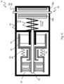
- the Figure 9 shows schematically a section through the braking device 14 in the open state according to a further embodiment.
- the braking device 14 and its components namely the adjusting element 18, the first energy storage 34 in the form of a compression spring 46, the displacement-force converter 30, the second energy storage 48 in the form of a counterspring, the clutch 32 and the stop device 40 as well as the brake pads 38a , 38b are accommodated in a housing 44.
- the actuator 26 is designed as a hollow shaft drive and is in engagement with the release shaft 42.
- the clutch 32 can effect a force transmission through a frictional connection, which allows the brake 36 to be activated particularly quickly.
Landscapes
- Engineering & Computer Science (AREA)
- Mechanical Engineering (AREA)
- Maintenance And Inspection Apparatuses For Elevators (AREA)
- Braking Arrangements (AREA)
Claims (11)
- Ascenseur équipé d'un dispositif de freinage (14), en particulier d'un frein de service et/ou d'un dispositif d'arrêt,dans lequel le dispositif de freinage (14) est réalisé pour fournir une force de freinage variable (V) allant d'une force de freinage minimale jusqu'à une force de freinage maximale (Vmax),dans lequel un premier accumulateur d'énergie (34) est prévu pour fournir la force de freinage maximale (Vmax),dans lequel un deuxième accumulateur d'énergie (48) est prévu pour fournir une force antagoniste (Vg) réglable, dirigée à l'opposé de la force de freinage maximale (Vmax),dans lequel la force de freinage variable (V) est la différence entre la force de freinage maximale (Vmax) et la force antagoniste réglable (Vg),dans lequel un premier chemin de déclenchement (I) et un deuxième chemin de déclenchement (II) sont prévus pour déclencher le dispositif de freinage (14), dans lequel le dispositif de freinage (14) est réalisé pour fournir la force de freinage variable (V) lorsqu'un premier chemin de déclenchement (I) est actif, et le dispositif de freinage (14) est réalisé pour fournir la force de freinage maximale (Vmax) lorsqu'un deuxième chemin de déclenchement est actif (II),caractérisé en ce qu'un élément de déclenchement (24) est prévu pour déconnecter le deuxième accumulateur d'énergie (48) lorsque le deuxième chemin de déclenchement (II) est actif, dans lequel, après la déconnexion du deuxième accumulateur d'énergie (48), le deuxième accumulateur d'énergie (48) est découplé du premier accumulateur d'énergie (34).
- Ascenseur selon la revendication 1, dans lequel le premier accumulateur d'énergie (34) présente un ressort de compression (46) pour fournir la force de freinage maximale (Vmax).
- Ascenseur selon la revendication 1 ou 2, dans lequel le deuxième accumulateur d'énergie (48) présente un ressort antagoniste pour fournir la force antagoniste (Vg).
- Ascenseur selon la revendication 1, 2 ou 3, dans lequel un élément de réglage (18) est prévu en coopération avec le deuxième accumulateur d'énergie (48) pour régler la force antagoniste réglable (Vg).
- Ascenseur selon la revendication 4, dans lequel l'élément de réglage (18) présente un actionneur (26) pour charger et décharger le deuxième accumulateur d'énergie (48).
- Ascenseur selon la revendication 5, dans lequel l'actionneur (26) est réalisé comme un entraînement à arbre creux.
- Ascenseur selon l'une quelconque des revendications 1 à 6, dans lequel un dispositif d'accouplement (32) est prévu comme élément de déclenchement (24).
- Ascenseur selon l'une quelconque des revendications 1 à 7, dans lequel un régulateur (16) pour régler la force de freinage variable (V) est associé au premier chemin de déclenchement (I).
- Ascenseur selon l'une quelconque des revendications 1 à 8, dans lequel le premier chemin de déclenchement (1) est réalisé en fonctionnant avec verrouillage sous tension.
- Ascenseur selon l'une quelconque des revendications 1 à 9, dans lequel le deuxième chemin de déclenchement (II) est réalisé en fonctionnant avec verrouillage hors tension.
- Ascenseur selon l'une quelconque des revendications 1 à 10, dans lequel le dispositif de freinage (14) présente une transmission autobloquante (28) pour régler la force de freinage variable (V), qui est associée au premier chemin de déclenchement (I).
Applications Claiming Priority (2)
| Application Number | Priority Date | Filing Date | Title |
|---|---|---|---|
| DE102014116281.1A DE102014116281A1 (de) | 2014-11-07 | 2014-11-07 | Aufzug mit einer Bremsvorrichtung |
| PCT/EP2015/074757 WO2016071141A1 (fr) | 2014-11-07 | 2015-10-26 | Ascenseur équipé d'un dispositif de freinage |
Publications (2)
| Publication Number | Publication Date |
|---|---|
| EP3215449A1 EP3215449A1 (fr) | 2017-09-13 |
| EP3215449B1 true EP3215449B1 (fr) | 2023-11-29 |
Family
ID=54364310
Family Applications (1)
| Application Number | Title | Priority Date | Filing Date |
|---|---|---|---|
| EP15787539.4A Active EP3215449B1 (fr) | 2014-11-07 | 2015-10-26 | Ascenseur équipé d'un dispositif de freinage |
Country Status (7)
| Country | Link |
|---|---|
| US (1) | US10351387B2 (fr) |
| EP (1) | EP3215449B1 (fr) |
| KR (1) | KR101941388B1 (fr) |
| CN (1) | CN107074490B (fr) |
| DE (1) | DE102014116281A1 (fr) |
| FI (1) | FI3215449T3 (fr) |
| WO (1) | WO2016071141A1 (fr) |
Families Citing this family (5)
| Publication number | Priority date | Publication date | Assignee | Title |
|---|---|---|---|---|
| DE102015218025B4 (de) * | 2015-09-18 | 2019-12-12 | Thyssenkrupp Ag | Aufzugsystem |
| DE102016200593A1 (de) * | 2016-01-19 | 2017-07-20 | Thyssenkrupp Ag | Bremseinrichtung für einen Fahrkorb eines Aufzugsystems |
| DE102016217790A1 (de) | 2016-09-16 | 2018-03-22 | Thyssenkrupp Ag | Bremsvorrichtung für eine Aufzugsanlage |
| ES2882640T3 (es) * | 2017-06-01 | 2021-12-02 | Kone Corp | Disposición y procedimiento para cambiar la dirección de movimiento de una cabina de un ascensor, y el ascensor correspondiente |
| ES3031284T3 (en) | 2021-03-31 | 2025-07-07 | Inventio Ag | Elevator brake system |
Citations (1)
| Publication number | Priority date | Publication date | Assignee | Title |
|---|---|---|---|---|
| US6719101B2 (en) * | 2000-12-08 | 2004-04-13 | Inventio Ag | Safety brake with retardation-dependent braking force |
Family Cites Families (11)
| Publication number | Priority date | Publication date | Assignee | Title |
|---|---|---|---|---|
| JPH04333487A (ja) * | 1991-05-09 | 1992-11-20 | Hitachi Ltd | エレベーター並びに制動装置 |
| FI105091B (fi) * | 1997-01-30 | 2000-06-15 | Kone Corp | Johdejarru |
| US6193026B1 (en) * | 1997-12-22 | 2001-02-27 | Otis Elevator Company | Elevator brake |
| KR100951518B1 (ko) * | 2003-10-07 | 2010-04-07 | 오티스 엘리베이터 컴파니 | 원격 리셋 가능한 로프 없는 엘리베이터용 비상 정지 장치 |
| MY192706A (en) * | 2004-12-17 | 2022-09-02 | Inventio Ag | Lift installation with a braking device, and method for braking and holding a lift installation |
| DE502007007014D1 (de) * | 2007-11-12 | 2011-06-01 | Thyssenkrupp Elevator Ag | Bremsvorrichtung zum Bremsen eines Fahrkorbs |
| CN101463874A (zh) * | 2007-12-19 | 2009-06-24 | 谢兴云 | 常闭式制动器的叠加制动推动装置 |
| CN103648954B (zh) * | 2011-09-30 | 2016-01-20 | 因温特奥股份公司 | 带有机电致动的制动装置 |
| CN106660743B (zh) | 2014-05-20 | 2019-08-27 | 维托控股有限公司 | 用于电梯运行的安全装置 |
| DE102014111359A1 (de) | 2014-05-20 | 2015-11-26 | Wittur Holding Gmbh | Verfahren zum Betrieb einer Fahrkorbbremseinheit |
| PL3197812T3 (pl) * | 2014-09-24 | 2019-01-31 | Inventio Ag | Hamulec windy |
-
2014
- 2014-11-07 DE DE102014116281.1A patent/DE102014116281A1/de not_active Withdrawn
-
2015
- 2015-10-26 CN CN201580060545.4A patent/CN107074490B/zh active Active
- 2015-10-26 KR KR1020177015213A patent/KR101941388B1/ko not_active Expired - Fee Related
- 2015-10-26 WO PCT/EP2015/074757 patent/WO2016071141A1/fr not_active Ceased
- 2015-10-26 EP EP15787539.4A patent/EP3215449B1/fr active Active
- 2015-10-26 US US15/522,352 patent/US10351387B2/en not_active Expired - Fee Related
- 2015-10-26 FI FIEP15787539.4T patent/FI3215449T3/fi active
Patent Citations (1)
| Publication number | Priority date | Publication date | Assignee | Title |
|---|---|---|---|---|
| US6719101B2 (en) * | 2000-12-08 | 2004-04-13 | Inventio Ag | Safety brake with retardation-dependent braking force |
Also Published As
| Publication number | Publication date |
|---|---|
| DE102014116281A1 (de) | 2016-05-12 |
| US10351387B2 (en) | 2019-07-16 |
| FI3215449T3 (fi) | 2024-02-26 |
| WO2016071141A1 (fr) | 2016-05-12 |
| CN107074490B (zh) | 2019-02-12 |
| US20170320706A1 (en) | 2017-11-09 |
| CN107074490A (zh) | 2017-08-18 |
| EP3215449A1 (fr) | 2017-09-13 |
| KR20170084144A (ko) | 2017-07-19 |
| KR101941388B1 (ko) | 2019-01-22 |
Similar Documents
| Publication | Publication Date | Title |
|---|---|---|
| EP0773180B1 (fr) | Procédé et dispositif pour augmenter la sécurité des ascenseurs | |
| EP1979260B1 (fr) | Ensemble de commande et de régulation pour sécuriser un dispositif transporteur, dispositif transporteur et système de grue | |
| EP3126276B1 (fr) | Ascenseur équipé d'un dispositif de freinage | |
| EP3177555B1 (fr) | Ascenseur, système de freinage d'ascenseur et procédé de commande d'une installation de freinage d'un ascenseur | |
| EP2058262B2 (fr) | Dispositif de freinage destiné au freinage d'une cabine | |
| DE102014017094B4 (de) | Servosteuervorrichtung mit Funktion zur Verringerung des Absenkens bei einem Bremsvorgang | |
| DE102007015277A1 (de) | Aufzugsanlage mit einer Aufzugskabinenbremseinrichtung und Verfahren zum Bremsen einer Aufzugskabine | |
| EP3873845B1 (fr) | Ensemble de freinage pour sécuriser un dispositif transporteur, dispositif transporteur et système de grue | |
| DE102013111385A1 (de) | Auslösevorrichtung einer Fangvorrichtung für eine Aufzugskabine einer Aufzugsanlage | |
| EP3122679A1 (fr) | Dispositif de freinage d'une cabine d'une installation d'ascenseur | |
| EP2887535A1 (fr) | Système d'entraînement et de commande pour portes relevables | |
| EP3215449A1 (fr) | Ascenseur équipé d'un dispositif de freinage | |
| DE102012016336A1 (de) | Geschwindigkeitsbegrenzer für ein Aufzugsystem | |
| EP1671912A1 (fr) | Système d'ascenseur avec unité de freinage et méthode pour mantenir l'ascenseur en position arrêtée | |
| EP0292685B1 (fr) | Entraînement d'élévateur avec appareil de commande pour déplacement sans à coup | |
| WO2020115304A1 (fr) | Frein de cabine actionné par un fluide sous pression et système de soupape pour commander la fonction de frein d'urgence du frein de cabine actionné par un fluide sous pression d'un système d'ascenseur | |
| DE202012104436U1 (de) | Sicherheitseinrichtung für eine Aufzugkabine einer Aufzuganlage | |
| DE202016101183U1 (de) | Aufzug mit einem Sicherheitscontroller zum unmittelbaren Beeinflussen der Bremskraft | |
| DE102012111071A1 (de) | Sicherheitseinrichtung für eine Aufzugkabine einer Aufzuganlage und Verfahren zur Sicherung einer Aufzugkabine | |
| WO2016005429A1 (fr) | Installation d'ascenseur équipée d'un dispositif de freinage sur la cabine et procédé servant à faire fonctionner ladite installation d'ascenseur | |
| WO2024061766A1 (fr) | Procédé de fonctionnement d'un système d'ascenseur | |
| DE102011001449A1 (de) | Sicherheitsfangvorrichtung für eine Aufzugsanlage sowie Verfahren zur Sicherung einer schienengeführten Aufzugskabine einer Aufzugsanlage | |
| DE19635244C2 (de) | Sicherheits- Bremsvorrichtung für Seilförderanlagen | |
| WO2017121760A1 (fr) | Procédé de surveillance d'un premier frein d'une cabine de système d'ascenseur | |
| DE112021007075T5 (de) | Aufzugvorrichtung |
Legal Events
| Date | Code | Title | Description |
|---|---|---|---|
| STAA | Information on the status of an ep patent application or granted ep patent |
Free format text: STATUS: THE INTERNATIONAL PUBLICATION HAS BEEN MADE |
|
| PUAI | Public reference made under article 153(3) epc to a published international application that has entered the european phase |
Free format text: ORIGINAL CODE: 0009012 |
|
| STAA | Information on the status of an ep patent application or granted ep patent |
Free format text: STATUS: REQUEST FOR EXAMINATION WAS MADE |
|
| 17P | Request for examination filed |
Effective date: 20170503 |
|
| AK | Designated contracting states |
Kind code of ref document: A1 Designated state(s): AL AT BE BG CH CY CZ DE DK EE ES FI FR GB GR HR HU IE IS IT LI LT LU LV MC MK MT NL NO PL PT RO RS SE SI SK SM TR |
|
| AX | Request for extension of the european patent |
Extension state: BA ME |
|
| RAP1 | Party data changed (applicant data changed or rights of an application transferred) |
Owner name: THYSSENKRUPP ELEVATOR AG Owner name: THYSSENKRUPP AG |
|
| DAV | Request for validation of the european patent (deleted) | ||
| DAX | Request for extension of the european patent (deleted) | ||
| RAP1 | Party data changed (applicant data changed or rights of an application transferred) |
Owner name: THYSSENKRUPP AG Owner name: THYSSENKRUPP ELEVATOR AG |
|
| STAA | Information on the status of an ep patent application or granted ep patent |
Free format text: STATUS: EXAMINATION IS IN PROGRESS |
|
| 17Q | First examination report despatched |
Effective date: 20191010 |
|
| TPAC | Observations filed by third parties |
Free format text: ORIGINAL CODE: EPIDOSNTIPA |
|
| TPAC | Observations filed by third parties |
Free format text: ORIGINAL CODE: EPIDOSNTIPA |
|
| RAP1 | Party data changed (applicant data changed or rights of an application transferred) |
Owner name: THYSSENKRUPP ELEVATOR INNOVATION AND OPERATIONS AG |
|
| RAP3 | Party data changed (applicant data changed or rights of an application transferred) |
Owner name: TK ELEVATOR INNOVATION AND OPERATIONS GMBH |
|
| GRAP | Despatch of communication of intention to grant a patent |
Free format text: ORIGINAL CODE: EPIDOSNIGR1 |
|
| STAA | Information on the status of an ep patent application or granted ep patent |
Free format text: STATUS: GRANT OF PATENT IS INTENDED |
|
| INTG | Intention to grant announced |
Effective date: 20230719 |
|
| GRAS | Grant fee paid |
Free format text: ORIGINAL CODE: EPIDOSNIGR3 |
|
| GRAA | (expected) grant |
Free format text: ORIGINAL CODE: 0009210 |
|
| STAA | Information on the status of an ep patent application or granted ep patent |
Free format text: STATUS: THE PATENT HAS BEEN GRANTED |
|
| AK | Designated contracting states |
Kind code of ref document: B1 Designated state(s): AL AT BE BG CH CY CZ DE DK EE ES FI FR GB GR HR HU IE IS IT LI LT LU LV MC MK MT NL NO PL PT RO RS SE SI SK SM TR |
|
| REG | Reference to a national code |
Ref country code: GB Ref legal event code: FG4D Free format text: NOT ENGLISH |
|
| REG | Reference to a national code |
Ref country code: CH Ref legal event code: EP |
|
| REG | Reference to a national code |
Ref country code: DE Ref legal event code: R096 Ref document number: 502015016691 Country of ref document: DE |
|
| REG | Reference to a national code |
Ref country code: IE Ref legal event code: FG4D Free format text: LANGUAGE OF EP DOCUMENT: GERMAN |
|
| REG | Reference to a national code |
Ref country code: FI Ref legal event code: FGE |
|
| REG | Reference to a national code |
Ref country code: LT Ref legal event code: MG9D |
|
| REG | Reference to a national code |
Ref country code: NL Ref legal event code: MP Effective date: 20231129 |
|
| PG25 | Lapsed in a contracting state [announced via postgrant information from national office to epo] |
Ref country code: GR Free format text: LAPSE BECAUSE OF FAILURE TO SUBMIT A TRANSLATION OF THE DESCRIPTION OR TO PAY THE FEE WITHIN THE PRESCRIBED TIME-LIMIT Effective date: 20240301 |
|
| PG25 | Lapsed in a contracting state [announced via postgrant information from national office to epo] |
Ref country code: IS Free format text: LAPSE BECAUSE OF FAILURE TO SUBMIT A TRANSLATION OF THE DESCRIPTION OR TO PAY THE FEE WITHIN THE PRESCRIBED TIME-LIMIT Effective date: 20240329 |
|
| PG25 | Lapsed in a contracting state [announced via postgrant information from national office to epo] |
Ref country code: LT Free format text: LAPSE BECAUSE OF FAILURE TO SUBMIT A TRANSLATION OF THE DESCRIPTION OR TO PAY THE FEE WITHIN THE PRESCRIBED TIME-LIMIT Effective date: 20231129 |
|
| PG25 | Lapsed in a contracting state [announced via postgrant information from national office to epo] |
Ref country code: ES Free format text: LAPSE BECAUSE OF FAILURE TO SUBMIT A TRANSLATION OF THE DESCRIPTION OR TO PAY THE FEE WITHIN THE PRESCRIBED TIME-LIMIT Effective date: 20231129 |
|
| PG25 | Lapsed in a contracting state [announced via postgrant information from national office to epo] |
Ref country code: LT Free format text: LAPSE BECAUSE OF FAILURE TO SUBMIT A TRANSLATION OF THE DESCRIPTION OR TO PAY THE FEE WITHIN THE PRESCRIBED TIME-LIMIT Effective date: 20231129 Ref country code: IS Free format text: LAPSE BECAUSE OF FAILURE TO SUBMIT A TRANSLATION OF THE DESCRIPTION OR TO PAY THE FEE WITHIN THE PRESCRIBED TIME-LIMIT Effective date: 20240329 Ref country code: GR Free format text: LAPSE BECAUSE OF FAILURE TO SUBMIT A TRANSLATION OF THE DESCRIPTION OR TO PAY THE FEE WITHIN THE PRESCRIBED TIME-LIMIT Effective date: 20240301 Ref country code: ES Free format text: LAPSE BECAUSE OF FAILURE TO SUBMIT A TRANSLATION OF THE DESCRIPTION OR TO PAY THE FEE WITHIN THE PRESCRIBED TIME-LIMIT Effective date: 20231129 Ref country code: BG Free format text: LAPSE BECAUSE OF FAILURE TO SUBMIT A TRANSLATION OF THE DESCRIPTION OR TO PAY THE FEE WITHIN THE PRESCRIBED TIME-LIMIT Effective date: 20240229 |
|
| PG25 | Lapsed in a contracting state [announced via postgrant information from national office to epo] |
Ref country code: NL Free format text: LAPSE BECAUSE OF FAILURE TO SUBMIT A TRANSLATION OF THE DESCRIPTION OR TO PAY THE FEE WITHIN THE PRESCRIBED TIME-LIMIT Effective date: 20231129 |
|
| PG25 | Lapsed in a contracting state [announced via postgrant information from national office to epo] |
Ref country code: SE Free format text: LAPSE BECAUSE OF FAILURE TO SUBMIT A TRANSLATION OF THE DESCRIPTION OR TO PAY THE FEE WITHIN THE PRESCRIBED TIME-LIMIT Effective date: 20231129 Ref country code: RS Free format text: LAPSE BECAUSE OF FAILURE TO SUBMIT A TRANSLATION OF THE DESCRIPTION OR TO PAY THE FEE WITHIN THE PRESCRIBED TIME-LIMIT Effective date: 20231129 Ref country code: PL Free format text: LAPSE BECAUSE OF FAILURE TO SUBMIT A TRANSLATION OF THE DESCRIPTION OR TO PAY THE FEE WITHIN THE PRESCRIBED TIME-LIMIT Effective date: 20231129 Ref country code: NO Free format text: LAPSE BECAUSE OF FAILURE TO SUBMIT A TRANSLATION OF THE DESCRIPTION OR TO PAY THE FEE WITHIN THE PRESCRIBED TIME-LIMIT Effective date: 20240229 Ref country code: NL Free format text: LAPSE BECAUSE OF FAILURE TO SUBMIT A TRANSLATION OF THE DESCRIPTION OR TO PAY THE FEE WITHIN THE PRESCRIBED TIME-LIMIT Effective date: 20231129 Ref country code: LV Free format text: LAPSE BECAUSE OF FAILURE TO SUBMIT A TRANSLATION OF THE DESCRIPTION OR TO PAY THE FEE WITHIN THE PRESCRIBED TIME-LIMIT Effective date: 20231129 Ref country code: HR Free format text: LAPSE BECAUSE OF FAILURE TO SUBMIT A TRANSLATION OF THE DESCRIPTION OR TO PAY THE FEE WITHIN THE PRESCRIBED TIME-LIMIT Effective date: 20231129 |
|
| PG25 | Lapsed in a contracting state [announced via postgrant information from national office to epo] |
Ref country code: DK Free format text: LAPSE BECAUSE OF FAILURE TO SUBMIT A TRANSLATION OF THE DESCRIPTION OR TO PAY THE FEE WITHIN THE PRESCRIBED TIME-LIMIT Effective date: 20231129 |
|
| PG25 | Lapsed in a contracting state [announced via postgrant information from national office to epo] |
Ref country code: CZ Free format text: LAPSE BECAUSE OF FAILURE TO SUBMIT A TRANSLATION OF THE DESCRIPTION OR TO PAY THE FEE WITHIN THE PRESCRIBED TIME-LIMIT Effective date: 20231129 |
|
| PG25 | Lapsed in a contracting state [announced via postgrant information from national office to epo] |
Ref country code: SK Free format text: LAPSE BECAUSE OF FAILURE TO SUBMIT A TRANSLATION OF THE DESCRIPTION OR TO PAY THE FEE WITHIN THE PRESCRIBED TIME-LIMIT Effective date: 20231129 |
|
| PG25 | Lapsed in a contracting state [announced via postgrant information from national office to epo] |
Ref country code: SM Free format text: LAPSE BECAUSE OF FAILURE TO SUBMIT A TRANSLATION OF THE DESCRIPTION OR TO PAY THE FEE WITHIN THE PRESCRIBED TIME-LIMIT Effective date: 20231129 Ref country code: SK Free format text: LAPSE BECAUSE OF FAILURE TO SUBMIT A TRANSLATION OF THE DESCRIPTION OR TO PAY THE FEE WITHIN THE PRESCRIBED TIME-LIMIT Effective date: 20231129 Ref country code: RO Free format text: LAPSE BECAUSE OF FAILURE TO SUBMIT A TRANSLATION OF THE DESCRIPTION OR TO PAY THE FEE WITHIN THE PRESCRIBED TIME-LIMIT Effective date: 20231129 Ref country code: IT Free format text: LAPSE BECAUSE OF FAILURE TO SUBMIT A TRANSLATION OF THE DESCRIPTION OR TO PAY THE FEE WITHIN THE PRESCRIBED TIME-LIMIT Effective date: 20231129 Ref country code: EE Free format text: LAPSE BECAUSE OF FAILURE TO SUBMIT A TRANSLATION OF THE DESCRIPTION OR TO PAY THE FEE WITHIN THE PRESCRIBED TIME-LIMIT Effective date: 20231129 Ref country code: DK Free format text: LAPSE BECAUSE OF FAILURE TO SUBMIT A TRANSLATION OF THE DESCRIPTION OR TO PAY THE FEE WITHIN THE PRESCRIBED TIME-LIMIT Effective date: 20231129 Ref country code: CZ Free format text: LAPSE BECAUSE OF FAILURE TO SUBMIT A TRANSLATION OF THE DESCRIPTION OR TO PAY THE FEE WITHIN THE PRESCRIBED TIME-LIMIT Effective date: 20231129 |
|
| PG25 | Lapsed in a contracting state [announced via postgrant information from national office to epo] |
Ref country code: PT Free format text: LAPSE BECAUSE OF FAILURE TO SUBMIT A TRANSLATION OF THE DESCRIPTION OR TO PAY THE FEE WITHIN THE PRESCRIBED TIME-LIMIT Effective date: 20240401 |
|
| PG25 | Lapsed in a contracting state [announced via postgrant information from national office to epo] |
Ref country code: PT Free format text: LAPSE BECAUSE OF FAILURE TO SUBMIT A TRANSLATION OF THE DESCRIPTION OR TO PAY THE FEE WITHIN THE PRESCRIBED TIME-LIMIT Effective date: 20240401 |
|
| REG | Reference to a national code |
Ref country code: DE Ref legal event code: R097 Ref document number: 502015016691 Country of ref document: DE |
|
| PLBE | No opposition filed within time limit |
Free format text: ORIGINAL CODE: 0009261 |
|
| STAA | Information on the status of an ep patent application or granted ep patent |
Free format text: STATUS: NO OPPOSITION FILED WITHIN TIME LIMIT |
|
| PG25 | Lapsed in a contracting state [announced via postgrant information from national office to epo] |
Ref country code: SI Free format text: LAPSE BECAUSE OF FAILURE TO SUBMIT A TRANSLATION OF THE DESCRIPTION OR TO PAY THE FEE WITHIN THE PRESCRIBED TIME-LIMIT Effective date: 20231129 |
|
| PG25 | Lapsed in a contracting state [announced via postgrant information from national office to epo] |
Ref country code: SI Free format text: LAPSE BECAUSE OF FAILURE TO SUBMIT A TRANSLATION OF THE DESCRIPTION OR TO PAY THE FEE WITHIN THE PRESCRIBED TIME-LIMIT Effective date: 20231129 |
|
| 26N | No opposition filed |
Effective date: 20240830 |
|
| GBPC | Gb: european patent ceased through non-payment of renewal fee |
Effective date: 20241026 |
|
| PG25 | Lapsed in a contracting state [announced via postgrant information from national office to epo] |
Ref country code: MC Free format text: LAPSE BECAUSE OF FAILURE TO SUBMIT A TRANSLATION OF THE DESCRIPTION OR TO PAY THE FEE WITHIN THE PRESCRIBED TIME-LIMIT Effective date: 20231129 |
|
| PG25 | Lapsed in a contracting state [announced via postgrant information from national office to epo] |
Ref country code: GB Free format text: LAPSE BECAUSE OF NON-PAYMENT OF DUE FEES Effective date: 20241026 |
|
| PG25 | Lapsed in a contracting state [announced via postgrant information from national office to epo] |
Ref country code: BE Free format text: LAPSE BECAUSE OF NON-PAYMENT OF DUE FEES Effective date: 20241031 Ref country code: LU Free format text: LAPSE BECAUSE OF NON-PAYMENT OF DUE FEES Effective date: 20241026 |
|
| PG25 | Lapsed in a contracting state [announced via postgrant information from national office to epo] |
Ref country code: FR Free format text: LAPSE BECAUSE OF NON-PAYMENT OF DUE FEES Effective date: 20241031 |
|
| REG | Reference to a national code |
Ref country code: BE Ref legal event code: MM Effective date: 20241031 |
|
| PG25 | Lapsed in a contracting state [announced via postgrant information from national office to epo] |
Ref country code: IE Free format text: LAPSE BECAUSE OF NON-PAYMENT OF DUE FEES Effective date: 20241026 |
|
| REG | Reference to a national code |
Ref country code: CH Ref legal event code: U11 Free format text: ST27 STATUS EVENT CODE: U-0-0-U10-U11 (AS PROVIDED BY THE NATIONAL OFFICE) Effective date: 20251101 |
|
| REG | Reference to a national code |
Ref country code: AT Ref legal event code: MM01 Ref document number: 1635938 Country of ref document: AT Kind code of ref document: T Effective date: 20241026 |
|
| PGFP | Annual fee paid to national office [announced via postgrant information from national office to epo] |
Ref country code: DE Payment date: 20251021 Year of fee payment: 11 |
|
| PG25 | Lapsed in a contracting state [announced via postgrant information from national office to epo] |
Ref country code: AT Free format text: LAPSE BECAUSE OF NON-PAYMENT OF DUE FEES Effective date: 20241026 |
|
| PGFP | Annual fee paid to national office [announced via postgrant information from national office to epo] |
Ref country code: FI Payment date: 20251028 Year of fee payment: 11 |
|
| PGFP | Annual fee paid to national office [announced via postgrant information from national office to epo] |
Ref country code: CH Payment date: 20251101 Year of fee payment: 11 |
|
| PG25 | Lapsed in a contracting state [announced via postgrant information from national office to epo] |
Ref country code: CY Free format text: LAPSE BECAUSE OF FAILURE TO SUBMIT A TRANSLATION OF THE DESCRIPTION OR TO PAY THE FEE WITHIN THE PRESCRIBED TIME-LIMIT; INVALID AB INITIO Effective date: 20151026 |
|
| PG25 | Lapsed in a contracting state [announced via postgrant information from national office to epo] |
Ref country code: HU Free format text: LAPSE BECAUSE OF FAILURE TO SUBMIT A TRANSLATION OF THE DESCRIPTION OR TO PAY THE FEE WITHIN THE PRESCRIBED TIME-LIMIT; INVALID AB INITIO Effective date: 20151026 |