EP3215738B1 - Automatisches ringventil, schliesser für automatische ringventile und verfahren zur herstellung dieser schliesser - Google Patents
Automatisches ringventil, schliesser für automatische ringventile und verfahren zur herstellung dieser schliesser Download PDFInfo
- Publication number
- EP3215738B1 EP3215738B1 EP15788359.6A EP15788359A EP3215738B1 EP 3215738 B1 EP3215738 B1 EP 3215738B1 EP 15788359 A EP15788359 A EP 15788359A EP 3215738 B1 EP3215738 B1 EP 3215738B1
- Authority
- EP
- European Patent Office
- Prior art keywords
- ring
- structural core
- primary layer
- shutter
- shaped portion
- Prior art date
- Legal status (The legal status is an assumption and is not a legal conclusion. Google has not performed a legal analysis and makes no representation as to the accuracy of the status listed.)
- Active
Links
Images


Classifications
-
- F—MECHANICAL ENGINEERING; LIGHTING; HEATING; WEAPONS; BLASTING
- F16—ENGINEERING ELEMENTS AND UNITS; GENERAL MEASURES FOR PRODUCING AND MAINTAINING EFFECTIVE FUNCTIONING OF MACHINES OR INSTALLATIONS; THERMAL INSULATION IN GENERAL
- F16K—VALVES; TAPS; COCKS; ACTUATING-FLOATS; DEVICES FOR VENTING OR AERATING
- F16K11/00—Multiple-way valves, e.g. mixing valves; Pipe fittings incorporating such valves
- F16K11/02—Multiple-way valves, e.g. mixing valves; Pipe fittings incorporating such valves with all movable sealing faces moving as one unit
- F16K11/04—Multiple-way valves, e.g. mixing valves; Pipe fittings incorporating such valves with all movable sealing faces moving as one unit comprising only lift valves
-
- F—MECHANICAL ENGINEERING; LIGHTING; HEATING; WEAPONS; BLASTING
- F04—POSITIVE - DISPLACEMENT MACHINES FOR LIQUIDS; PUMPS FOR LIQUIDS OR ELASTIC FLUIDS
- F04B—POSITIVE-DISPLACEMENT MACHINES FOR LIQUIDS; PUMPS
- F04B39/00—Component parts, details, or accessories, of pumps or pumping systems specially adapted for elastic fluids, not otherwise provided for in, or of interest apart from, groups F04B25/00 - F04B37/00
- F04B39/10—Adaptations or arrangements of distribution members
- F04B39/102—Adaptations or arrangements of distribution members the members being disc valves
-
- B—PERFORMING OPERATIONS; TRANSPORTING
- B29—WORKING OF PLASTICS; WORKING OF SUBSTANCES IN A PLASTIC STATE IN GENERAL
- B29D—PRODUCING PARTICULAR ARTICLES FROM PLASTICS OR FROM SUBSTANCES IN A PLASTIC STATE
- B29D99/00—Subject matter not provided for in other groups of this subclass
- B29D99/0082—Producing articles in the form of closed loops, e.g. rings
- B29D99/0085—Producing articles in the form of closed loops, e.g. rings for sealing purposes
-
- F—MECHANICAL ENGINEERING; LIGHTING; HEATING; WEAPONS; BLASTING
- F04—POSITIVE - DISPLACEMENT MACHINES FOR LIQUIDS; PUMPS FOR LIQUIDS OR ELASTIC FLUIDS
- F04B—POSITIVE-DISPLACEMENT MACHINES FOR LIQUIDS; PUMPS
- F04B39/00—Component parts, details, or accessories, of pumps or pumping systems specially adapted for elastic fluids, not otherwise provided for in, or of interest apart from, groups F04B25/00 - F04B37/00
- F04B39/10—Adaptations or arrangements of distribution members
- F04B39/1053—Adaptations or arrangements of distribution members the members being Hoerbigen valves
-
- F—MECHANICAL ENGINEERING; LIGHTING; HEATING; WEAPONS; BLASTING
- F16—ENGINEERING ELEMENTS AND UNITS; GENERAL MEASURES FOR PRODUCING AND MAINTAINING EFFECTIVE FUNCTIONING OF MACHINES OR INSTALLATIONS; THERMAL INSULATION IN GENERAL
- F16K—VALVES; TAPS; COCKS; ACTUATING-FLOATS; DEVICES FOR VENTING OR AERATING
- F16K15/00—Check valves
- F16K15/02—Check valves with guided rigid valve members
- F16K15/08—Check valves with guided rigid valve members shaped as rings
-
- F—MECHANICAL ENGINEERING; LIGHTING; HEATING; WEAPONS; BLASTING
- F16—ENGINEERING ELEMENTS AND UNITS; GENERAL MEASURES FOR PRODUCING AND MAINTAINING EFFECTIVE FUNCTIONING OF MACHINES OR INSTALLATIONS; THERMAL INSULATION IN GENERAL
- F16K—VALVES; TAPS; COCKS; ACTUATING-FLOATS; DEVICES FOR VENTING OR AERATING
- F16K27/00—Construction of housing; Use of materials therefor
- F16K27/02—Construction of housing; Use of materials therefor of lift valves
- F16K27/0272—Construction of housing; Use of materials therefor of lift valves valves provided with a lining
-
- B—PERFORMING OPERATIONS; TRANSPORTING
- B29—WORKING OF PLASTICS; WORKING OF SUBSTANCES IN A PLASTIC STATE IN GENERAL
- B29K—INDEXING SCHEME ASSOCIATED WITH SUBCLASSES B29B, B29C OR B29D, RELATING TO MOULDING MATERIALS OR TO MATERIALS FOR MOULDS, REINFORCEMENTS, FILLERS OR PREFORMED PARTS, e.g. INSERTS
- B29K2071/00—Use of polyethers, e.g. PEEK, i.e. polyether-etherketone or PEK, i.e. polyetherketone or derivatives thereof, as moulding material
-
- B—PERFORMING OPERATIONS; TRANSPORTING
- B29—WORKING OF PLASTICS; WORKING OF SUBSTANCES IN A PLASTIC STATE IN GENERAL
- B29K—INDEXING SCHEME ASSOCIATED WITH SUBCLASSES B29B, B29C OR B29D, RELATING TO MOULDING MATERIALS OR TO MATERIALS FOR MOULDS, REINFORCEMENTS, FILLERS OR PREFORMED PARTS, e.g. INSERTS
- B29K2081/00—Use of polymers having sulfur, with or without nitrogen, oxygen or carbon only, in the main chain, as moulding material
- B29K2081/04—Polysulfides, e.g. PPS, i.e. polyphenylene sulfide or derivatives thereof
-
- B—PERFORMING OPERATIONS; TRANSPORTING
- B29—WORKING OF PLASTICS; WORKING OF SUBSTANCES IN A PLASTIC STATE IN GENERAL
- B29K—INDEXING SCHEME ASSOCIATED WITH SUBCLASSES B29B, B29C OR B29D, RELATING TO MOULDING MATERIALS OR TO MATERIALS FOR MOULDS, REINFORCEMENTS, FILLERS OR PREFORMED PARTS, e.g. INSERTS
- B29K2509/00—Use of inorganic materials not provided for in groups B29K2503/00 - B29K2507/00, as filler
- B29K2509/08—Glass
Definitions
- the present disclosure relates to automatic valves, such as ring valves. Some embodiments of the subject matter disclosed herein relate specifically to reciprocating compressor automatic ring valves. According to a further aspect, the disclosure relates to reciprocating compressors including said automatic ring valves. According to another aspect, the disclosure relates to a shutter for automatic ring valves. According to a further aspect, the disclosure relates to a method for manufacturing a ring shutter for an automatic ring valve.
- US 2003/085533 A1 discloses sealing elements for compressor valves.
- WO 2013/087615 A1 discloses an automatic valve.
- WO 2013/131976 A1 discloses an automatic valve.
- EP 1 221 554 A1 discloses a ring valve.
- US 4 854 341 A discloses a plate valve.
- Automatic valves are commonly used for example in reciprocating compressors. Automatic valves are arranged on both the suction side as well as the discharge side of the compressor, to automatically open and close the suction port and discharge port of the compressor under the control of the pressure inside the compressor cylinder.
- an automatic ring valve can comprise a valve guard and a valve seat, the latter provided with circumferentially arranged gas flow passages extending through the valve seat. Also the valve guard is provided with gas flow passages. A plurality of concentrically arranged shutter rings are placed between the valve seat and the valve guard. Each shutter ring is arranged along a set of corresponding annularly arranged gas flow passages of the valve seat. Compression springs are provided between the valve guard and each shutter ring to oppose the movement of the shutter ring from the closed position, wherein the respective set of gas flow passages are closed.
- Differential pressure across the valve causes automatic opening and closing of the valve.
- the crank shaft of reciprocating compressors using such valves can rotate at a rotary speed in the range of for example 100-1200 rpm and typically between 200 and 1000 rpm.
- the shutter rings are therefore subject to repeated opening and closing strokes at high speed. They are commonly made of composite material, such as short fiber-reinforced synthetic resin to reduce the mass thereof and thus the inertia.
- the valve seat and the valve guard are typically made of metal.
- an automatic ring valve system comprising a valve seat having gas flow passages arranged according to at least one annular row, and at least a shutter comprising at least a ring-shaped portion for selectively closing and opening the gas flow passages relative to an annular row.
- the valve system further comprises means, such as one or more resilient members, for contrasting the opening movement of the ring-shaped portion of the shutter from a closing position to an opening position.
- the ring-shaped portion of the shutter comprises a matrix or layer, preferably made of synthetic polymeric resin material and reinforced with fibers, wherein the ring-shaped portion of the shutter comprises a structural core made by said fiber-reinforced matrix, and wherein at least a portion of said structural core is covered by at least one primary layer, designed to improve fracture and/or impact and/or wear resistance of said ring-shaped portion.
- the idea is that of having a shutter or a shutter portion made of different parts, each specialized to guarantee particular mechanical resistance.
- the structural core provides the overall ring toughness, while the primary layer provides good damping and/or impact, and or fracture toughness and/or wear resistance.
- the primary layer is made with the same kind of matrix resin, but with different kind of fillers/fibers, such that the quantity and the type of the different fillers/fibers provides the different needed technical effect of the primary layer.
- the ring-shaped portion comprises at least one primary layer, designed to improve fracture and/or impact resistance of said ring-shaped portion, and at least an external layer, designed to improve in particular the wear resistance of the ring-shaped portion, arranged to cover or to surround the primary layer.
- the same external layer can decrease the friction coefficient with the parts the shutter is in contact with.
- the external layer is made only by a polymeric resin without fillers or fibers, that can be the same resin as the primary layer, or other resin.
- the external layer can include fillers/fibers adapted to increase wear resistance or reduce friction coefficient (e.g. copper oxide or organic nanoparticles).
- At least a primary layer is directly arranged on said structural core and said at least one external layer is directly arranged on said at least primary layer.
- the ring-shaped portion comprises only the structural core with only the primary layer that can encompass also fillers/fibers adapted to increase wear resistance or reduce friction coefficient.
- first and second layer are integrated together in a single layer.
- the least one ring-shaped portion comprises a concentric structure, wherein the structural core is surrounded by said primary layers; or a sandwich structure, wherein the structural core is comprised between two opposite primary layers lying on two correspondent planes orthogonal to the central axis of said at least one ring-shaped portion, or an overlapped structure, wherein only one primary layer is overlapped to a face of said structural core orthogonal to the central axis of said at least one ring-shaped portion, i.e. the structural core is protected only on one face.
- the external layer(s) can be located on the primary layer(s).
- At least some of the fibers of the structural core are continuous fibers and develop for at least 360° of the annular development of the ring-shaped portion of the shutter. Surprisingly, this configuration of ring-shaped portion of the shutter allows obtaining high buckling strength during opening/closing impacts and gives overall ring toughness.
- the use of continuous fibers allows a significant increase of the filler fraction of the ring-shaped portion of the shutter, i.e. the percentage of fibers in the ring-shaped portion of the shutter.
- Increased amounts of filler in the resin matrix in turn reduce the coefficient of thermal expansion of the ring-shaped portion of the shutter, thus substantially reducing the difference between the thermal expansion of the shutter and the thermal expansion coefficient of the valve seat and reduces the sensitivity of the valve efficiency to temperature changes.
- the structural core is formed by pre-impregnated (“prepreg”) composite continuous fibers.
- the matrix of the structural core has a layered structure with layers including said continuous fibers.
- the matrix of the structural core is formed by wound portions of at least one elongated flexible element comprising said continuous fibers developing in the direction of the flexible element, wherein said wound portions are bonded together.
- the flexible element comprises a polymeric resin and continuous fibers, with fibers arranged in and along the development of the flexible element.
- An elongated flexible element can be "endless", or in the form of a tape, a tow, a strip, a rope, a line, a belt, a band, a ribbon etc.
- Said flexible element can comprise pre-impregnated composite continuous fibers.
- the continuous fibers surround the central axis of said ring-shaped portion of the shutter.
- the continuous fibers are arranged according to a substantially helical development about the axis of the ring-shaped portion. According to other preferred embodiments, the continuous fibers develop in a substantially spiral development about the center of said ring-shaped portion.
- the amount of the continuous fibers is comprised between 30% and 80% by weight on the total weight of the ring-shaped portion.
- the linear thermal expansion coefficient, in the same direction of the continuous fibers is comprised between 0.05 ⁇ 10 -6 /°C and 10 ⁇ 10 -6 /°C.
- the polymeric resin can be of the thermoplastic or thermoset type.
- the polymeric resin is chosen from the group comprising Polyetheretherketone (PEEK), polyaryletherketones (PAEK), Polyphenylene Sulfide (PPS), Polysulfone (PSU), Polyphenylene Sulfide (PPS), Polyamide (PA), polyphthalamide (PPA), polyamide-imide (PAI), Polyethylene (PE), Polycarbonates (PC), Polyetherimide (PEI), polytetrafluoroethylene (PTFE), Polyimide (PI), polybenzimidazole (PBI), or epoxy resins.
- the continuous fibers are chosen from the group comprising glass fibers, E-glass fibers, ECR-glass fibers, S-glass fibers, carbon fibers, STD carbon fibers, IM carbon fibers, HM carbon fibers, UHM carbon fibers, aramid fibers.
- the least one primary layer comprises resin with filler embedded, wherein said resin is preferably a polymeric resin, preferably of the thermoplastic or thermoset type and filler.
- the polymeric resin of the primary layer is chosen from the group comprising Polyetheretherketone (PEEK), Polyaryletherketones (PAEK), Polyphenylene Sulfide (PPS), Polysulfone (PSU), Polyamide (PA), Polyphthalamide (PPA), Polyamide-Imide (PAI), Polyethylene (PE), Polycarbonates (PC), Polyetherimide (PEI), Polytetrafluoroethylene (PTFE), Polyimide (PI), Polybenzimidazole (PBI), or Epoxy Resins.
- PEEK Polyetheretherketone
- PAEK Polyaryletherketones
- PPS Polyphenylene Sulfide
- PSU Polysulfone
- PA Polyamide
- PA Polyphthalamide
- PAI Polyamide-Imide
- PE Polyethylene
- PC Polycarbonates
- PC Polyetherimide
- PEI Polytetrafluoroethylene
- PI Polyimide
- PBI Polybenzimidazole
- the fillers are fibers, preferably continuous and/or chopped fibers, preferably chosen from the group comprising glass fibers, E-glass fibers, ECR-glass fibers, S-glass fibers, carbon fibers, STD carbon fibers, IM carbon fibers, HM carbon fibers, UHM carbon fibers, aramid fibers; preferably the quantity of the fibers in the said at least one primary layer is comprised between 0% and 50% by weight on the total weight of the primary layer of the ring-shaped portion.
- the fillers can comprise or also be chosen from the group comprising: nanoparticles e.g. Al 2 O 3 (Alumina), Si 3 N 4 (Silicon Nitride), SiO 2 (Silicon Dioxide), CaCO 3 (Calcium carbonate), CuO (Copper oxide), Fe 3 O 4 (magnetite), WS 2 (tungstenite), and/or Nanotubes e.g Single Wall Carbon Nanotube (SWCN), Multi-Wall Carbon Nanotube (MWCN), Carbon Nanofiber (CNF), and/or Nanoclay e.g. montmorillonite.
- nanoparticles e.g. Al 2 O 3 (Alumina), Si 3 N 4 (Silicon Nitride), SiO 2 (Silicon Dioxide), CaCO 3 (Calcium carbonate), CuO (Copper oxide), Fe 3 O 4 (magnetite), WS 2 (tungstenite), and/or Nanotubes e.g Single Wall Carbon Nanotube (SWCN), Multi-Wall Carbon Nanotube (MWCN
- the amount of the fillers in the said primary layer is comprised between 0% and 10% by weight on the total weight of the primary layer of the ring-shaped portion; if the fillers is Fe 3 O 4 (magnetite), the quantity of the filler in the at least one primary layer is comprised between 0% and 55% by weight on the total weight of the primary layer of the ring-shaped portion.
- the external layer comprises resin with filler embedded, wherein said resin is preferably a polymeric resin, preferably of the thermoplastic or thermoset type and filler.
- the polymeric resin of the external layer is chosen from the group comprising Polyetheretherketone (PEEK), Polyaryletherketones (PAEK), Polyphenylene Sulfide (PPS), Polysulfone (PSU), Polyamide (PA), Polyphthalamide (PPA), Polyamide-Imide (PAI), Polyethylene (PE), Polycarbonates (PC), Polyetherimide (PEI), Polytetrafluoroethylene (PTFE), Polyimide (PI), Polybenzimidazole (PBI), or Epoxy Resins.
- PEEK Polyetheretherketone
- PAEK Polyaryletherketones
- PPS Polyphenylene Sulfide
- PSU Polysulfone
- PA Polyamide
- PA Polyphthalamide
- PAI Polyamide-Imide
- PE Polyethylene
- PC Polycarbonates
- PC Polyetherimide
- PEI Polytetrafluoroethylene
- PI Polyimide
- PBI Polybenzimidazole
- the fillers are fibers, preferably continuous and/or chopped fibers, preferably chosen from the group comprising glass fibers, E-glass fibers, ECR-glass fibers, S-glass fibers, carbon fibers, STD carbon fibers, IM carbon fibers, HM carbon fibers, UHM carbon fibers, aramid fibers; preferably the quantity of the fibers in the said external layer is comprised between 0% and 50% by weight on the total weight of the external layer of the ring-shaped portion.
- the fillers can comprise or also be chosen from the group comprising: nanoparticles e.g. Al 2 O 3 (Alumina), Si 3 N 4 (Silicon Nitride), SiO 2 (Silicon Dioxide), CaCO; (Calcium carbonate), CuO (Copper oxide), Fe 3 O 4 (magnetite), WS 2 (tungstenite), and/or Nanotubes e.g Single Wall Carbon Nanotube (SWCN), Multi-Wall Carbon Nanotube (MWCN), Carbon Nanofiber (CNF), and/or Nanoclay e.g. montmorillonite.
- nanoparticles e.g. Al 2 O 3 (Alumina), Si 3 N 4 (Silicon Nitride), SiO 2 (Silicon Dioxide), CaCO; (Calcium carbonate), CuO (Copper oxide), Fe 3 O 4 (magnetite), WS 2 (tungstenite), and/or Nanotubes e.g Single Wall Carbon Nanotube (SWCN), Multi-Wall Carbon Nanotube (MWCN
- the amount of the fillers in the said external layer is comprised between 0% and 10% by weight on the total weight of the external layer of the ring-shaped portion; if the fillers is Fe 3 O 4 (magnetite), the quantity of the filler in the external layer is comprised between 0% and 55% by weight on the total weight of the external layer of the ring-shaped portion.
- the at least one external layer is deprived of fillers or fibers, and comprises only resin of the type chosen from the group comprising Polyetheretherketone (PEEK), Polyaryletherketones (PAEK), Polyphenylene Sulfide (PPS), Polysulfone (PSU), Polyamide (PA), Polyphthalamide (PPA), Polyamide-Imide (PAI), Polyethylene (PE), Polycarbonates (PC), Polyetherimide (PEI), Polytetrafluoroethylene (PTFE), Polyimide (PI), Polybenzimidazole (PBI), or Epoxy Resins.
- PEEK Polyetheretherketone
- PAEK Polyaryletherketones
- PPS Polyphenylene Sulfide
- PSU Polysulfone
- PA Polyamide
- PPA Polyphthalamide
- PAI Polyamide-Imide
- PE Polyethylene
- PC Polycarbonates
- PC Polyetherimide
- PEI Polytetrafluoroethylene
- PI Polyimide
- PBI
- the shutter can be made of single concentrical rings separated one from the other.
- the shutter can be made in one piece and comprises a plurality of coaxially arranged ring-shaped portions connected to one another by one or more transversal portions.
- the new structure of the valve shutter according to the invention increases durability of the shutter in comparison with the valves plastic rings of the known type, improving impact resistance and stiffness.
- the subject matter disclosed herein provides for a shutter for an automatic ring valve according to one or more of the preceding embodiments mentioned above.
- the shutter is in form of a ring adapted for closing/opening a relative annular row of gas flow passages arranged in the valve seat of the automatic ring valve; according another point of view, the shutter can be made of single concentrical independent rings (therefore each ring is a ring-shaped portion of the shutter).
- the shutter comprises a plurality of coaxial a ring-shaped portions joined together forming a one- piece body for closing/opening the gas flow passages arranged in annular rows in the valve seat.
- the subject matter disclosed herein provides for the use of a ring-shaped portion body according to one or more of the preceding embodiments provided above, as a shutter or a portion of shutter of an automatic ring valve.
- the subject matter disclosed herein provides for a method for manufacturing a shutter or a shutter portion for an automatic ring valve, comprising the steps of producing a structural core, having a ring or circular-shape, comprising a matrix with polymeric resin and fibers, producing, on said structural core, at least a primary layer comprising a polymeric resin and fibers, forming a ring or circular-shape one-piece product comprising said structural core and said at least a primary layer, machining the said one-piece product to form the shutter or shutter portion.
- the step of producing the at least a primary layer on said structural core comprising the steps of compression moulding said at least a primary layer on the existing structural core, or injection moulding said at least a primary layer on the existing structural core, or spray or bath coating said at least a primary layer on the existing structural core.
- the method comprises the step of producing, before said machining step, an external layer on said at least a primary layer, comprising a polymeric resin with or without fillers or fibers, forming a ring or circular-shape one-piece product comprising structural core, at least a primary layer and said external layer.
- the step of producing the external layer on said at least a primary layer comprises the step of compression moulding said external layer on the existing primary layer, or injection moulding said external layer on the existing primary layer, or spray or bath coating said external layer on the existing primary layer.
- the step of producing said structural core comprises the steps of winding at least one elongated flexible element comprising a polymeric resin and continuous fibers, with fibers arranged in and along the flexible element, on and around a cylindrical structure, such that a substantially cylindrical multilayers configuration is formed; bonding the layers of said at least one flexible element to form an intermediate one-piece product having a broadly cylindrical shape; cutting at least one ring-shaped portion from a part of said intermediate one piece product.
- This method allows providing shutters for automatic ring valve in an economic manner and with increased mechanical properties.
- the flexible element comprises a polymeric resin and continuous fibers, with fibers arranged in and along the development of the flexible element.
- An flexible element can be "endless” or in the form of a tape, a tow, a strip, a rope, a line, a belt, a band, a ribbon etc.
- the flexible element can comprise pre-impregnated composite continuous fibers.
- the structural core can be cut or machined out from the intermediate one-piece product, for example, by conventional or not conventional machining, such as turning, boring, drilling, milling, laser cutting, water jet cutting ecc..
- the ring-shaped portion can be cut or machined out from the one-piece product, for example, by conventional or not conventional machining, such as turning, boring, drilling, milling, laser cutting, water jet cutting ecc..
- the one-piece product is divided into annular slices and then said at least one ring-shaped portion is cut from an annular slice.
- One or more rings of a shutter can be obtained from a single annular slice.
- the intermediate one-piece product is divided into annular slices and then said structural core is cut from an annular slice.
- One or more structural cores can be obtained from a single annular slice.
- the one-piece product is divided into annular slices and then the shutter is formed by making through holes, preferably slots or elongated holes through an annular slice such that the shutter is made in one piece and comprises a coaxial plurality of ring-shaped portions and a plurality of transversal portions joining together the ring-shaped portions.
- the silhouette of the one piece shutter between the external and internal ring-shaped portions can be complementary to the silhouette of relative part of the valve plate.
- the intermediate one-piece product is divided into annular slices and then the structural core is formed by making through holes, preferably slots or elongated holes through an annular slice such that the structural core is made in one piece and comprises a coaxial plurality of ring-shaped portions and a plurality of transversal portions joining together the ring-shaped portions.
- the silhouette of the one piece structural core between the external and internal ring-shaped portions can be complementary to the silhouette of relative part of the valve plate.
- said at least one flexible element is wound helicoidally around and along the axis of the cylindrical structure. Therefore, the flexible element moves relative to the cylindrical structure (or vice-versa) with rotation and translation parallel to the axis.
- the at least one flexible element is wound in a substantially inclined manner with respect to the axis of the cylindrical structure.
- the at least one flexible element is wound around said cylindrical structure according to automated fiber placement (AFP) technique.
- AFP automated fiber placement
- the at least one flexible element is wound spirally around the axis of the cylindrical structure. Therefore, in this case, the flexible element moves relative to the cylindrical structure (or vice-versa) only with rotation around the axis.
- the at least one flexible element is wound in a substantially orthogonal manner with respect to the axis of the cylindrical structure.
- the at least one flexible element is a tape wound around said cylindrical structure according to automated tape laying (ATL) technique.
- ATL automated tape laying
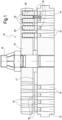
- the automatic ring valve 10 comprises a valve seat 12 and a valve guard 13.
- the valve seat is provided with circumferentially arranged gas flow passages 14 extending through the valve seat 12.
- the valve guard 13 is in turn provided with gas flow passages 15.
- a central screw 16 connects the valve seat 12 and the valve guard 13 to one another leaving a space 17 there between.
- a plurality of concentrically arranged shutter rings 18 is provided between the valve seat 12 and the valve guard 13. Each shutter ring 18 is arranged along a set of corresponding annularly arranged gas flow passages 14 of the valve seat 12.
- a plurality of contrasting members for contrasting an opening movement of the shutter rings 18 are provided; as an example, these members consist of a plurality of resilient members, as compression springs 19, for each shutter ring 18 for biasing the shutter ring 18 in a closed position, wherein the shutter ring 18 closes the respective set of gas flow passages 14 by sealingly contacting corresponding sealing surfaces of the gas flow passages 14.
- the compression springs 19 are housed in respective spring pockets 20 provided in the valve guard 13.
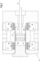
- FIG. 2 illustrates the head 21 of a reciprocating compressor using four automatic ring valves 10 arranged on the suction ports and discharge ports of the compressor and designated 10A, 10B, 10C, 10D.
- the compressor head 21 defines a compressor cylinder 23 wherein a piston 24 is reciprocatingly movable.
- a rod 25 of the piston 24 is connected to a crank (not shown), which reciprocatingly moves the piston 24 according to double arrow f24.
- the piston 24 divides the cylinder 23 into two separate compression chambers 23A, 23B.
- the compressor head 21 is provided with a first suction port 27 in fluid communication with the first compression chamber 23A through a first automatic ring valve 10A.
- a second suction port 29 is in fluid communication with the second compression chamber 23B through a second automatic ring valve 10B.
- a first discharge port 31 is in fluid communication with the first compression chamber 23A through a third automatic ring valve 10C and a second discharge port 33 is in fluid communication with the second compression chamber 23B through a fourth automatic ring valve 10D.
- the reciprocating motion of the piston 24 causes selectively suction of the gas in the first compression chamber 23A and discharge of compressed gas from the second compression chamber 23B and vice versa.
- the automatic ring valves 10A, 10B, 10C and 10D selectively open when the pressure in the first gas flow passages 14 exceeds the resilient force of the springs 19.
- the crank shaft of reciprocating compressors can rotate at a rotary speed in the range of for example 100-1200 rpm and typically between 200 and 1000 rpm.
- the shutter rings 18 are therefore subject to repeated opening and closing strokes at high speed.
- the valve seat 12 and the valve guard 13 are, as an example, made of metal.
- Each shutter ring 18 comprises a structural core 18A made by a fiber-reinforced matrix 40, described below, in order to reduce the inertia of the moving shutter.
- At least a portion of said structural core 18A is covered by at least one primary layer 18B, and if needed, an external layer 18C, designed to improve fracture and/or impact and/or wear resistance of said ring-shaped portion.
- the fibers of the fiber-reinforced matrix are continuous fibers 41, and at least a group of them develops for at least 360° of the annular development of the ring. Preferably almost the totality of the fibers are continuous fibers developing for more than 360° of the annular development of the ring.
- the continuous fibers 41 of the structural core 18A surround the central axis Z1 of said shutter ring 18.
- a schematic sectional diameter views of a shutter ring 18 are shown in figures 5-14 , wherein continuous fibers 41 are depicted by little dots ( fig. 5-10 ) or concentric circles ( fig. 11, 12 , 14, 15 ).
- the matrix 40 comprises a polymeric resin wherein the fibers 41 (continuous or not) are embedded.
- the polymeric resin is Polyetheretherketone (PEEK), that is a thermoplastic resin.
- polymeric resin can be chosen, as an example, from the group comprising Polyetheretherketone (PEEK), polyaryletherketones (PAEK), Polyphenylene Sulfide (PPS), Polysulfone (PSU), Polyphenylene Sulfide (PPS), Polyamide (PA), polyphthalamide (PPA), polyamide-imide (PAI), Polyethylene (PE), Polycarbonates (PC), Polyetherimide (PEI), polytetrafluoroethylene (PTFE), Polyimide (PI), polybenzimidazole (PBI), or epoxy resins.
- PEEK Polyetheretherketone
- PAEK Polyaryletherketones
- PPS Polyphenylene Sulfide
- PSU Polysulfone
- PPS Polyphenylene Sulfide
- PPS Polyamide
- PA polyphthalamide
- PAI polyamide-imide
- PE Polyethylene
- PC Polycarbonates
- PC Polyetherimide
- PEI polytetrafluoroethylene
- PI
- the resin can be also of the thermoset type.
- the fibers 41 are chosen from the group comprising glass fibers, E-glass fibers, ECR-glass fibers, S-glass fibers, carbon fibers, STD carbon fibers, IM carbon fibers, HM carbon fibers, UHM carbon fibers, aramid fibers.
- the quantity of the fibers in the structural core 18A is comprised between 30% and 80% by weight on the total weight of the structural core of the ring-shaped portion.
- the linear thermal expansion coefficient, in the same direction of the fibers (in the case of a ring-shaped object, a circumferential direction), of the structural core is comprised between 0.05 ⁇ 10 -6 /°C and 10 ⁇ 10 -6 /°C.
- the linear thermal expansion coefficient is 0.27 ⁇ 10 -6 /°C.
- continuous fibers allows the increase of the filler fraction in the ring material, with reduction of the differential of the coefficient of expansion, in absolute value, of the valve seat material and of the shutter ring material and, at the same time, a surprising increase of the buckling strength of the shutter during opening/closing impacts, with clear benefits in terms of durability and toughness of the shutter and in terms of reliability of the sealing of valve.
- the matrix of the of the structural core 18A has a layered structure with layers including said fibers (continuous fibers).
- the matrix can be formed by wound portions of flexible element, as a tape T (or other kind of flexible elements as defined above) comprising the continuous fibers 41 developing in the direction of the flexible element.
- the wound portions are bonded together forming the structure of the shutter.
- the bonding action can be a thermobonding action.
- annular piece 42 with cylindrical shape, made of a wound tape with a lay up of 90° - arrow R1 - (that means that, at every winding round, the new tape portion overlaps the underlying tape portion with constant width; the tape has a lay up of 90° with respect to the winding axis Z1).
- the tape is formed as the matrix 40, that is a polymeric structure wherein the continuous fibers are embedded, developing in the direction of the tape.
- the continuous fibers overlaps according to a substantially orthogonal direction with respect to the axis Z1 of the intermediate annular piece 42 (the projection of a continuous fiber develops in a plane orthogonal to the axis Z1 of the piece 42).
- the continuous fibers 41 develop in a substantially spiral development about the center/axis of the piece 42.
- a ring forming the structural core 18A can be cut off (see figure 13 , wherein the shape of a ring 18A is depicted, by an hidden line, inside the longitudinal sectional view of a portion of annular piece 42; in figure 14 , the portion of the structural core 18A cut off by the intermediate annular piece 42, is shown).
- a structural core 18A can be manufactured directly winding, on a mandrel with diameter equal to the internal diameter of the ring 18A, a tape with a width equal to the height (dimension parallel to the axis) of the ring 18A, until the external diameter of the wound tape is equal to the external diameter of the ring.
- the cutting off is preferably made in such a way that the continuous fibers develop in a substantially orthogonal development with respect to the axis Z1 of the structural core 18A (a continuous fiber develops in a plane orthogonal to the axis of the ring 18A).
- FIG 12 is shown a further annular piece 43, with cylindrical shape, like an annular billet, having an height longer than the height of the annular piece 42 of figure 5 .
- the further annular piece 43 can be made of a wound tape with a lay up of 90° with width greater than the width of the tape of the case of figure 11 .
- the further annular piece 43 can be made of a wound flexible element with a lay up different from 90°, with width similar to the width of the tape of the case of figure 5 . That means that the continuous fibers develop in a substantially helical development about the axis Z3 (the winding axis) of further annular piece 43. Practically speaking, the continuous fibers develop in a substantially inclined development (e.g. 45° from the axis direction 0°) with respect to the axis Z3 of annular piece 43 (arrow R2).
- one or more prepreg composite tows can be used, wherein the polymeric resin used for impregnating the continuous fibers, as such the fibers, can be of the same type of the tape solutions.
- At least a portion of the structural core 18A is covered by at least one primary layer 18B, designed to improve fracture and/or impact and/or wear resistance of said ring-shaped portion.
- the idea is that of having a shutter or a shutter portion made of different parts, each specialized to guarantee particular mechanical resistance.
- the primary layer 18B is made with the same kind of matrix resin of the structural core 18A, but with different kind of fillers/fibers, such that the quantity and the type of the different fillers/fibers provides the different needed technical effect of the primary layer.
- FIG 5 an embodiment of portion of shutter is shown, wherein the structural core 18A is surrounded by a primary layer 18B, forming a concentric structure.
- FIG 7 an embodiment of portion of shutter is shown, wherein the structural core 18A is comprised between two opposite primary layers 18B, like a sandwich structure, wherein the two opposite primary layers lie on two correspondent planes orthogonal to the central axis Z the one ring-shaped portion 18.
- FIG 9 an embodiment of portion of shutter is shown, wherein only one primary layer 18B is overlapped to a face of said structural core 18A orthogonal to the central axis Z of the ring-shaped portion 18, i.e. the structural core 18A is protected only on one face.
- the ring-shaped portion 18 comprises the structural core 18A, one (or more) primary layer 18B, designed to improve fracture and/or impact resistance of said ring-shaped portion, and one external layer 18C, designed to improve in particular the wear resistance of the ring-shaped portion, arranged to cover or to surround the primary layer 18B.
- the external layer 18C can decrease the friction coefficient with the parts the shutter is in contact with.
- the external layer 18C is made only by a polymeric resin without fillers or fibers, that can be the same resin as the primary layer 18B, that can be the same resin of structural core 18A, or other resin.
- the external layer 18C can include fillers/fibers adapted to increase wear resistance or reduce friction coefficient (e.g. copper oxide or organic nanoparticles).
- the primary layer 18B is directly arranged on the structural core 18A the external layer 18C is directly arranged on the primary layer 18B.
- figure 6 is shown the structural core 18A surrounded by the primary layer 18B and by the external layer 18C, forming a concentric structure.
- figure 8 is shown a sandwich structure wherein external layer 18C and primary layer 18B are located on opposite faces of the structural core 18A.
- the primary layer 18B and the external layer 18C are overlapped to only a face of said structural core 18A orthogonal to the central axis Z of the ring-shaped portion 18.
- the ring-shaped portion comprises only the structural core 18A with only the primary layer 18B that can encompass also fillers/fibers adapted to increase wear resistance or reduce friction coefficient (as external layer).
- first and second layer are integrated together in a single layer.
- the primary layer 18B comprises resin with filler embedded, wherein the resin is preferably a polymeric resin, preferably of the thermoplastic or thermoset type and filler.
- the polymeric resin of the primary layer 18B, or of the external layer 18C is chosen from the group comprising Polyetheretherketone (PEEK), Polyaryletherketones (PAEK), Polyphenylene Sulfide (PPS), Polysulfone (PSU), , Polyamide (PA), Polyphthalamide (PPA), Polyamide-Imide (PAI), Polyethylene (PE), Polycarbonates (PC), Polyetherimide (PEI), Polytetrafluoroethylene (PTFE), Polyimide (PI), Polybenzimidazole (PBI), or Epoxy Resins.
- PEEK Polyetheretherketone
- PAEK Polyaryletherketones
- PPS Polyphenylene Sulfide
- PSU Polysulfone
- PA Polyamide
- PA Polyphthalamide
- PAI Polyamide-Imide
- PE Polyethylene
- PC Polycarbonates
- PC Polyetherimide
- PTFE Polytetrafluoroethylene
- PI Polyimide
- PBI Polybenz
- the fillers are fibers, preferably continuous and/or chopped fibers, preferably chosen from the group comprising glass fibers, E-glass fibers, ECR-glass fibers, S-glass fibers, carbon fibers, STD carbon fibers, IM carbon fibers, HM carbon fibers, UHM carbon fibers, aramid fibers; preferably the quantity of the fibers in the said at least one primary layer or external layer is comprised between 0% and 50% by weight on the total weight of the primary layer or external layer of the ring-shaped portion.
- the fillers in the layers can also comprises nanoparticles e.g. Al 2 O 3 (Alumina), SiO 2 (Silicon Dioxide), Si 3 N 4 (Silicon Nitride) CaCO; (Calcium carbonate), Fe 3 O 4 (magnetite), CuO (Copper oxide), WS 2 (tungstenite), and/or Nanotubes e.g Single Wall Carbon Nanotube (SWCN), Multi-Wall Carbon Nanotube (MWCN), Carbon Nanofiber (CNF), and/or Nanoclay e.g. montmorillonite.
- nanoparticles e.g. Al 2 O 3 (Alumina), SiO 2 (Silicon Dioxide), Si 3 N 4 (Silicon Nitride) CaCO; (Calcium carbonate), Fe 3 O 4 (magnetite), CuO (Copper oxide), WS 2 (tungstenite), and/or Nanotubes e.g Single Wall Carbon Nanotube (SWCN), Multi-Wall Carbon Nanotube (MWCN), Carbon Nanofiber (C
- the amount of the fillers in the primary layer 18B is comprised between 0% and 10% by weight on the total weight of the primary layer ring-shaped portion; if the fillers is Fe 3 O 4 (magnetite), the quantity of the filler in the primary layer 18B is comprised between 0% and 55% by weight on the total weight of the primary layer of the ring-shaped portion.
- valve shutter 118 is shown in one piece of concentric ring-shaped portions 18 joined together by transversal portions 18A.
- those transversal portions 18A are provided along radial direction of the ring portions 18.
- a method for manufacturing a shutter or a shutter portion for an automatic ring valve comprises the steps of producing a structural core 18A, having a ring or circular-shape, comprising a polymeric resin and fibers, producing, on said structural core, at least a primary layer 18B comprising a polymeric resin and fibers, forming a ring or circular-shape one-piece product comprising said structural core 18A and said at least a primary layer 18B, machining the said one-piece product to form the shutter or shutter portion 18.
- a method for manufacturing the structural core 18A of a for an automatic ring valve comprises the steps of winding at least one flexible element T comprising a polymeric resin and continuous fibers 41, with fibers arranged in and along the flexible element T, on and around a cylindrical structure, such that a substantially cylindrical multilayers configuration is formed, bonding the layers of said at least one flexible element to form an intermediate one-piece product having a broadly cylindrical shape, cutting the structural core 18A from a part of said intermediate one piece product.
- the cutting off of the structural core 18A can be made, for example, by conventional or not conventional machining, as turning, boring, drilling, milling, laser cutting, water jet cutting etc.
- annular billet 43 Considering the case of the intermediate one piece product in the form of an annular billet 43, the latter can be divided into annular slices (similar to the annular body 42) and then the structural core 18A is cut off from one annular slice as stated before at point (c).
- From one annular slice can be provided one or more structural cores.
- the intermediate one piece product 42 (or a slice of the annular billet 43) is cut off by making through holes, preferably slots or elongated holes, through the thickness of the piece (axial direction), such that the structural core 118A is comprised of a coaxial plurality of ring-shaped portions 18' and a plurality of transversal portions 18" joining together the ring-shaped portions 18'.
- the silhouette of the structural core 118A between the external and internal ring-shaped portions 18Ex and 18In can be complementary to the silhouette of relative part of the valve plate.
- one or more "endless” or elongated flexible elements can be wound helicoidally around and along the axis Z3 of the cylindrical structure (the annular billet 43). Therefore, the flexible elements move relative to the cylindrical structure (or vice-versa) with rotation and translation parallel to the axis Z3. That means that the flexible elements are wound in a substantially inclined manner with respect to the axis Z3 of the cylindrical structure 43.
- one or more tows are wound around said cylindrical structure according to automated fiber placement (AFP) technique.
- one or more flexible elements are wound spirally around the axis Z1 of the cylindrical structure 42 o 43. Therefore, in this case, the flexible elements move relative to the cylindrical structure (or vice-versa) only with rotation around the axis Z1. Therefore the flexible elements are wound in a substantially orthogonal manner with respect to the axis of the cylindrical structure 42, 43.
- one tape is wound around said cylindrical structure according to automated tape laying (ATL) technique.
- the step of producing the at least a primary layer 18B on said structural core 18A comprises the steps of compression moulding the primary layer 18B on the existing structural core 18A, or injection moulding the primary layer on the existing structural core, or spray or bath coating the primary layer on the existing structural core.
- the method comprises the step of producing, before said machining step, an external layer 18C on the primary layer 18B, comprising a polymeric resin without fillers or fibers, forming a ring or circular-shape one-piece product comprising structural core 18A, primary layer 18B and said external layer 18C.
- the step of producing the external layer can comprises the step of compression moulding the external layer 18C on the existing primary layer 18B, or injection moulding said external layer on the existing primary layer, or spray or bath coating said external layer on the existing primary layer.
Landscapes
- Engineering & Computer Science (AREA)
- General Engineering & Computer Science (AREA)
- Mechanical Engineering (AREA)
- Laminated Bodies (AREA)
Claims (14)
- Automatisches Ringventil (10), umfassend:einen Ventilsitz (12), der mit einer Vielzahl von Gasdurchflusskanälen (14), die gemäß mindestens einer kranzförmigen Reihe angeordnet ist, versehen ist,mindestens einen Verschluss, umfassend mindestens einen ringförmigen Abschnitt (18) zum selektiven Schließen und Öffnen der Gasdurchflusskanäle (14),mindestens ein kontrastierendes Element (19) zum Kontrastieren einer Öffnungsbewegung des ringförmigen Abschnitts (18) des Verschlusses,wobei der ringförmige Abschnitt (18) des Verschlusses einen Strukturkern (18A), der mindestens teilweise aus einer faserverstärkten Matrix (40) hergestellt ist, umfasst und dadurch gekennzeichnet, dass mindestens ein Abschnitt des Strukturkerns (18A) mittels mindestens einer primären Schicht (18B) bedeckt ist, womit eine Bruch- und/oder Schlag- und/oder Verschleißfestigkeit des ringförmigen Abschnitts (18) verbessert wird,wobei der Strukturkern (18A) Endlosfasern (41) umfasst, wobei sich mindestens einige der Endlosfasern für mindestens 360° der kranzförmigen Entwicklung des ringförmigen Abschnitts (18) entwickeln.
- Automatisches Ringventil nach Anspruch 1, wobei der mindestens eine ringförmige Abschnitt (18) eine konzentrische Struktur aufweist, wobei der Strukturkern (18A) mittels der primären Schicht (18B) vollständig umgeben ist; odereine Sandwichstruktur, wobei der Strukturkern (18A) zwischen zwei gegenüberliegenden Schutzschichten, die an zwei gegenüberliegenden Oberflächen des Strukturkerns (18A) liegen, angeordnet ist, wobei die Oberflächen orthogonal zu einer Mittelachse des mindestens einen ringförmigen Abschnitts (18) sind, odereine überlappte Struktur, wobei die primäre Schicht (18B) angeordnet ist, um nur eine Fläche des Strukturkerns (18A) orthogonal zu der Mittelachse des mindestens einen ringförmigen Abschnitts (18) zu bedecken.
- Automatisches Ringventil nach Anspruch 1 oder 2, wobei der ringförmige Abschnitt (18) die mindestens eine primäre Schicht (18B), die ausgelegt ist, um die Bruch- und/oder Schlagfestigkeit des ringförmigen Abschnitts (18) zu verbessern, und mindestens eine externe Schicht (18C) umfasst, die ausgelegt ist, um die Verschleißfestigkeit des ringförmigen Abschnitts (18) zu verbessern, die angeordnet ist, um die mindestens eine primäre Schicht (18B) zu bedecken oder zu umgeben, wobei die primäre Schicht (18B) zwischen der externen Schicht (18C) und dem Strukturkern (18A) angeordnet ist.
- Automatisches Ringventil nach Anspruch 3, wobei die mindestens eine primäre Schicht (18B) an dem Strukturkern (18A) direkt angeordnet ist und die mindestens eine externe Schicht (18C) an der mindestens primären Schicht (18B) direkt angeordnet ist.
- Automatisches Ringventil nach Anspruch 1, wobei die Matrix (40), die den Strukturkern (18A) ausbildet, eine geschichtete Struktur aufweist.
- Hubkolbenverdichter, umfassend ein automatisches Ringventil (10) nach einem oder mehreren der vorstehenden Ansprüche.
- Verfahren zum Fertigen eines Verschlusses oder eines Verschlussabschnitts für ein automatisches Ringventil (10) nach einem oder mehreren der Ansprüche 1 bis 5, umfassend die Schritte eines Produzierens eines Strukturkerns (18A), der eine Ring- oder Kreisform aufweist, umfassend ein polymeres Harz und Fasern, wobei der Strukturkern (18A) Endlosfasern (41) umfasst, wobei sich mindestens einige der Endlosfasern für mindestens 360° der kranzförmigen Entwicklung des ringförmigen Abschnitts (18) entwickeln,des Produzierens, an dem Strukturkern (18A), mindestens einer primären Schicht (18B), umfassend ein polymeres Harz und Fasern, wobei ein einstückiges Produkt (18) der Ring- oder Kreisform, umfassend den Strukturkern (18A) und mindestens eine primäre Schicht, ausgebildet wird undeines Bearbeitens des einstückigen Produkts der Ring- oder Kreisform, um den Verschluss- oder Verschlussabschnitt auszubilden.
- Verfahren nach Anspruch 7, wobei der Schritt des Produzierens der mindestens einen primären Schicht (18B) an dem Strukturkern (18A) die Schritte umfasstFormpressen der mindestens einen primären Schicht (18B) auf den vorhandenen Strukturkern (18A) oderSpritzgießen der mindestens einen primären Schicht (18B) auf den vorhandenen Strukturkern (18A) oderSprüh- oder Badbeschichten der mindestens einen primären Schicht (18B) auf den vorhandenen Strukturkern (18A).
- Verfahren nach Anspruch 7 oder 8, umfassend den Schritt des Produzierens, vor dem Bearbeitungsschritt, einer externen Schicht (18C) an der mindestens einen primären Schicht (18B), umfassend ein polymeres Harz ohne Füllstoffe oder Fasern, wobei ein einstückiges Produkt der Ring- oder Kreisform, umfassend den Strukturkern (18A), die mindestens eine primäre Schicht (18B) und die externe Schicht (18C), ausgebildet wird.
- Verfahren nach Anspruch 9, wobei der Schritt des Produzierens der externen Schicht (18C) an der mindestens einen primären Schicht (18B) den Schritt umfasstFormpressen der externen Schicht (18C) auf die vorhandene primäre Schicht (18B) oderSpritzgießen der externen Schicht (18C) auf die vorhandene primäre Schicht (18B) oderSprüh- oder Badbeschichten der externen Schicht (18C) auf die vorhandene primäre Schicht (18B).
- Verfahren nach einem oder mehreren der Ansprüche 7 bis 10, wobei der Schritt des Produzierens des Strukturkerns (18A) die Schritte umfasstderartiges Wickeln mindestens eines flexiblen Elements, umfassend ein polymeres Harz und Endlosfasern (41), mit Fasern, die in und entlang dem flexiblen Elements angeordnet sind, auf und um eine zylindrische Struktur herum, dass eine im Wesentlichen zylindrische Mehrfachschichtkonfiguration ausgebildet wird,Verbinden der Schichten des mindestens einen flexiblen Elements, um ein einstückiges Produkt, das eine weitgehend zylindrische Form aufweist, auszubilden,Schneiden mindestens eines ringförmigen Abschnitts von einem Teil des einstückigen Produkts.
- Verfahren nach Anspruch 11, wobei das einstückige Produkt in kranzförmige Scheiben unterteilt ist und dann der mindestens eine ringförmige Abschnitt aus einer kranzförmigen Scheibe herausgearbeitet wird.
- Verfahren nach Anspruch 12, wobei das einstückige Produkt in kranzförmige Scheiben unterteilt ist und dann der Verschluss mittels eines Herstellens von Durchgangslöcher durch eine kranzförmige Scheibe derart ausgebildet wird, dass der Verschluss in einem Stück hergestellt ist und eine koaxiale Vielzahl von ringförmigen Abschnitten und eine Vielzahl von Querabschnitten, die die ringförmigen Abschnitte zusammenfügt, umfasst.
- Verfahren nach Anspruch 11, 12 oder 13, wobei das mindestens eine flexible Element entlang und um die Achse der zylindrischen Struktur herum schraubenförmig oder um die Achse der zylindrischen Struktur herum spiralförmig gewickelt ist.
Applications Claiming Priority (2)
| Application Number | Priority Date | Filing Date | Title |
|---|---|---|---|
| ITFI20140246 | 2014-11-05 | ||
| PCT/EP2015/074647 WO2016071128A1 (en) | 2014-11-05 | 2015-10-23 | Automatic ring valve, shutters for automatic ring valves, and method for manufacturing said shutters |
Publications (2)
| Publication Number | Publication Date |
|---|---|
| EP3215738A1 EP3215738A1 (de) | 2017-09-13 |
| EP3215738B1 true EP3215738B1 (de) | 2023-12-20 |
Family
ID=52232280
Family Applications (1)
| Application Number | Title | Priority Date | Filing Date |
|---|---|---|---|
| EP15788359.6A Active EP3215738B1 (de) | 2014-11-05 | 2015-10-23 | Automatisches ringventil, schliesser für automatische ringventile und verfahren zur herstellung dieser schliesser |
Country Status (3)
| Country | Link |
|---|---|
| US (1) | US11293556B2 (de) |
| EP (1) | EP3215738B1 (de) |
| WO (1) | WO2016071128A1 (de) |
Families Citing this family (3)
| Publication number | Priority date | Publication date | Assignee | Title |
|---|---|---|---|---|
| JP7362637B2 (ja) * | 2018-03-08 | 2023-10-17 | ブルクハルト コンプレッション アーゲー | 板弁およびその作動方法 |
| WO2020107068A1 (en) * | 2018-11-28 | 2020-06-04 | Lisle Darren | An improved compressor valve |
| EP4656868A1 (de) * | 2024-05-27 | 2025-12-03 | Danfoss A/S | Steuerplatte für eine hydraulische maschine |
Family Cites Families (10)
| Publication number | Priority date | Publication date | Assignee | Title |
|---|---|---|---|---|
| US4307751A (en) * | 1979-11-29 | 1981-12-29 | Edison International, Inc. | Plate valve |
| AT398809B (de) * | 1987-07-01 | 1995-02-27 | Hoerbiger Ventilwerke Ag | Plattenventil für einen kompressor |
| US6164702A (en) * | 1999-06-07 | 2000-12-26 | Adc Acquisition Company | Reinforced thermoplastic pipe couping |
| EP1221554A1 (de) * | 2000-12-28 | 2002-07-10 | RC Group S.p.A. | Ringventil für einen Kolbenverdichter |
| AT411258B (de) * | 2001-11-07 | 2003-11-25 | Hoerbiger Kompressortech Serv | Dichtelemente für kompressorventile |
| ITMI20012824A1 (it) | 2001-12-28 | 2003-06-28 | Nuovo Pignone Spa | Materiale plastico autolubrificante per elementi di tenuta |
| ITFI20110268A1 (it) * | 2011-12-12 | 2013-06-13 | Nuovo Pignone Spa | "automatic valve with interchangeable seat plate" |
| ITFI20120048A1 (it) * | 2012-03-08 | 2013-09-09 | Nuovo Pignone Srl | "automatic valve with a spring holder ring" |
| ITFI20130243A1 (it) * | 2013-10-16 | 2015-04-17 | Nuovo Pignone Srl | "automatic ring valve, shutters for automatic ring valves, and method for manufacturing said shutters" |
| US10086571B2 (en) * | 2015-02-12 | 2018-10-02 | Integrated Composite Products, Inc. | Pre-stressed fiber reinforcing member and method for its manufacture |
-
2015
- 2015-10-23 EP EP15788359.6A patent/EP3215738B1/de active Active
- 2015-10-23 WO PCT/EP2015/074647 patent/WO2016071128A1/en not_active Ceased
- 2015-10-23 US US15/524,799 patent/US11293556B2/en active Active
Also Published As
| Publication number | Publication date |
|---|---|
| WO2016071128A1 (en) | 2016-05-12 |
| US11293556B2 (en) | 2022-04-05 |
| US20170335979A1 (en) | 2017-11-23 |
| EP3215738A1 (de) | 2017-09-13 |
Similar Documents
| Publication | Publication Date | Title |
|---|---|---|
| EP3058258B1 (de) | Automatisches ringventil, schliesser für automatische ringventile und verfahren zur herstellung dieser schliesser | |
| US11635157B2 (en) | Non-metallic flexible pipe and manufacturing method thereof | |
| US11293556B2 (en) | Automatic ring valve, shutters for automatic ring valves, and method for manufacturing said shutters | |
| US11181011B2 (en) | Lighter-weight casing made of composite material and method of manufacturing same | |
| US8248748B2 (en) | Ducting for a fuel pipeline of aircraft or spacecraft, method for producing same and aircraft wing incorporating same | |
| US20080022524A1 (en) | Intake cone in a fiber compound material for a gas turbine engine and method for its manufacture | |
| US20090226310A1 (en) | Containment cases and method of manufacture | |
| US20150314556A1 (en) | Composite article and methods therefor | |
| US11149584B2 (en) | Containment case having ceramic coated fibers | |
| US7011111B2 (en) | Sealing elements for compressor valves | |
| US10619767B2 (en) | Tubular pipe with a composite holding strip | |
| EP3075524B1 (de) | Druckschott und verfahren zur herstellung eines druckschotts | |
| CA2835003A1 (en) | A flexible unbonded pipe | |
| CN111919054B (zh) | 柔性管体和方法 | |
| CA2834805A1 (en) | An unbonded flexible pipe | |
| US20170082221A1 (en) | Aircraft bleeding duct in composite material related application | |
| US11131329B2 (en) | Pneumatic actuator | |
| JP7394608B2 (ja) | 流体圧式アクチュエータ及び人工筋肉 | |
| CA3118431C (en) | Apparatus, systems, and methods for a reinforced seal element for joints on a drilling tool | |
| US11802639B2 (en) | Composite tubular element and relevant manufacturing method | |
| EA043152B1 (ru) | Композитный трубчатый элемент и способ его изготовления |
Legal Events
| Date | Code | Title | Description |
|---|---|---|---|
| STAA | Information on the status of an ep patent application or granted ep patent |
Free format text: STATUS: THE INTERNATIONAL PUBLICATION HAS BEEN MADE |
|
| PUAI | Public reference made under article 153(3) epc to a published international application that has entered the european phase |
Free format text: ORIGINAL CODE: 0009012 |
|
| STAA | Information on the status of an ep patent application or granted ep patent |
Free format text: STATUS: REQUEST FOR EXAMINATION WAS MADE |
|
| 17P | Request for examination filed |
Effective date: 20170606 |
|
| AK | Designated contracting states |
Kind code of ref document: A1 Designated state(s): AL AT BE BG CH CY CZ DE DK EE ES FI FR GB GR HR HU IE IS IT LI LT LU LV MC MK MT NL NO PL PT RO RS SE SI SK SM TR |
|
| AX | Request for extension of the european patent |
Extension state: BA ME |
|
| DAV | Request for validation of the european patent (deleted) | ||
| DAX | Request for extension of the european patent (deleted) | ||
| STAA | Information on the status of an ep patent application or granted ep patent |
Free format text: STATUS: EXAMINATION IS IN PROGRESS |
|
| 17Q | First examination report despatched |
Effective date: 20210127 |
|
| RAP1 | Party data changed (applicant data changed or rights of an application transferred) |
Owner name: NUOVO PIGNONE TECNOLOGIE - S.R.L. |
|
| P01 | Opt-out of the competence of the unified patent court (upc) registered |
Effective date: 20230526 |
|
| GRAP | Despatch of communication of intention to grant a patent |
Free format text: ORIGINAL CODE: EPIDOSNIGR1 |
|
| STAA | Information on the status of an ep patent application or granted ep patent |
Free format text: STATUS: GRANT OF PATENT IS INTENDED |
|
| RIC1 | Information provided on ipc code assigned before grant |
Ipc: F16K 15/08 20060101ALI20230906BHEP Ipc: F04B 39/10 20060101AFI20230906BHEP |
|
| INTG | Intention to grant announced |
Effective date: 20231009 |
|
| GRAS | Grant fee paid |
Free format text: ORIGINAL CODE: EPIDOSNIGR3 |
|
| GRAA | (expected) grant |
Free format text: ORIGINAL CODE: 0009210 |
|
| STAA | Information on the status of an ep patent application or granted ep patent |
Free format text: STATUS: THE PATENT HAS BEEN GRANTED |
|
| AK | Designated contracting states |
Kind code of ref document: B1 Designated state(s): AL AT BE BG CH CY CZ DE DK EE ES FI FR GB GR HR HU IE IS IT LI LT LU LV MC MK MT NL NO PL PT RO RS SE SI SK SM TR |
|
| REG | Reference to a national code |
Ref country code: GB Ref legal event code: FG4D |
|
| REG | Reference to a national code |
Ref country code: CH Ref legal event code: EP |
|
| REG | Reference to a national code |
Ref country code: DE Ref legal event code: R096 Ref document number: 602015087018 Country of ref document: DE |
|
| REG | Reference to a national code |
Ref country code: IE Ref legal event code: FG4D |
|
| REG | Reference to a national code |
Ref country code: NL Ref legal event code: FP |
|
| PG25 | Lapsed in a contracting state [announced via postgrant information from national office to epo] |
Ref country code: GR Free format text: LAPSE BECAUSE OF FAILURE TO SUBMIT A TRANSLATION OF THE DESCRIPTION OR TO PAY THE FEE WITHIN THE PRESCRIBED TIME-LIMIT Effective date: 20240321 |
|
| REG | Reference to a national code |
Ref country code: LT Ref legal event code: MG9D |
|
| PG25 | Lapsed in a contracting state [announced via postgrant information from national office to epo] |
Ref country code: LT Free format text: LAPSE BECAUSE OF FAILURE TO SUBMIT A TRANSLATION OF THE DESCRIPTION OR TO PAY THE FEE WITHIN THE PRESCRIBED TIME-LIMIT Effective date: 20231220 |
|
| PG25 | Lapsed in a contracting state [announced via postgrant information from national office to epo] |
Ref country code: ES Free format text: LAPSE BECAUSE OF FAILURE TO SUBMIT A TRANSLATION OF THE DESCRIPTION OR TO PAY THE FEE WITHIN THE PRESCRIBED TIME-LIMIT Effective date: 20231220 |
|
| PG25 | Lapsed in a contracting state [announced via postgrant information from national office to epo] |
Ref country code: LT Free format text: LAPSE BECAUSE OF FAILURE TO SUBMIT A TRANSLATION OF THE DESCRIPTION OR TO PAY THE FEE WITHIN THE PRESCRIBED TIME-LIMIT Effective date: 20231220 Ref country code: GR Free format text: LAPSE BECAUSE OF FAILURE TO SUBMIT A TRANSLATION OF THE DESCRIPTION OR TO PAY THE FEE WITHIN THE PRESCRIBED TIME-LIMIT Effective date: 20240321 Ref country code: FI Free format text: LAPSE BECAUSE OF FAILURE TO SUBMIT A TRANSLATION OF THE DESCRIPTION OR TO PAY THE FEE WITHIN THE PRESCRIBED TIME-LIMIT Effective date: 20231220 Ref country code: ES Free format text: LAPSE BECAUSE OF FAILURE TO SUBMIT A TRANSLATION OF THE DESCRIPTION OR TO PAY THE FEE WITHIN THE PRESCRIBED TIME-LIMIT Effective date: 20231220 Ref country code: BG Free format text: LAPSE BECAUSE OF FAILURE TO SUBMIT A TRANSLATION OF THE DESCRIPTION OR TO PAY THE FEE WITHIN THE PRESCRIBED TIME-LIMIT Effective date: 20240320 |
|
| REG | Reference to a national code |
Ref country code: AT Ref legal event code: MK05 Ref document number: 1642665 Country of ref document: AT Kind code of ref document: T Effective date: 20231220 |
|
| PG25 | Lapsed in a contracting state [announced via postgrant information from national office to epo] |
Ref country code: SE Free format text: LAPSE BECAUSE OF FAILURE TO SUBMIT A TRANSLATION OF THE DESCRIPTION OR TO PAY THE FEE WITHIN THE PRESCRIBED TIME-LIMIT Effective date: 20231220 Ref country code: RS Free format text: LAPSE BECAUSE OF FAILURE TO SUBMIT A TRANSLATION OF THE DESCRIPTION OR TO PAY THE FEE WITHIN THE PRESCRIBED TIME-LIMIT Effective date: 20231220 Ref country code: NO Free format text: LAPSE BECAUSE OF FAILURE TO SUBMIT A TRANSLATION OF THE DESCRIPTION OR TO PAY THE FEE WITHIN THE PRESCRIBED TIME-LIMIT Effective date: 20240320 Ref country code: LV Free format text: LAPSE BECAUSE OF FAILURE TO SUBMIT A TRANSLATION OF THE DESCRIPTION OR TO PAY THE FEE WITHIN THE PRESCRIBED TIME-LIMIT Effective date: 20231220 Ref country code: HR Free format text: LAPSE BECAUSE OF FAILURE TO SUBMIT A TRANSLATION OF THE DESCRIPTION OR TO PAY THE FEE WITHIN THE PRESCRIBED TIME-LIMIT Effective date: 20231220 |
|
| PG25 | Lapsed in a contracting state [announced via postgrant information from national office to epo] |
Ref country code: IS Free format text: LAPSE BECAUSE OF FAILURE TO SUBMIT A TRANSLATION OF THE DESCRIPTION OR TO PAY THE FEE WITHIN THE PRESCRIBED TIME-LIMIT Effective date: 20240420 |
|
| PG25 | Lapsed in a contracting state [announced via postgrant information from national office to epo] |
Ref country code: CZ Free format text: LAPSE BECAUSE OF FAILURE TO SUBMIT A TRANSLATION OF THE DESCRIPTION OR TO PAY THE FEE WITHIN THE PRESCRIBED TIME-LIMIT Effective date: 20231220 Ref country code: AT Free format text: LAPSE BECAUSE OF FAILURE TO SUBMIT A TRANSLATION OF THE DESCRIPTION OR TO PAY THE FEE WITHIN THE PRESCRIBED TIME-LIMIT Effective date: 20231220 |
|
| PG25 | Lapsed in a contracting state [announced via postgrant information from national office to epo] |
Ref country code: SK Free format text: LAPSE BECAUSE OF FAILURE TO SUBMIT A TRANSLATION OF THE DESCRIPTION OR TO PAY THE FEE WITHIN THE PRESCRIBED TIME-LIMIT Effective date: 20231220 |
|
| PG25 | Lapsed in a contracting state [announced via postgrant information from national office to epo] |
Ref country code: SM Free format text: LAPSE BECAUSE OF FAILURE TO SUBMIT A TRANSLATION OF THE DESCRIPTION OR TO PAY THE FEE WITHIN THE PRESCRIBED TIME-LIMIT Effective date: 20231220 Ref country code: SK Free format text: LAPSE BECAUSE OF FAILURE TO SUBMIT A TRANSLATION OF THE DESCRIPTION OR TO PAY THE FEE WITHIN THE PRESCRIBED TIME-LIMIT Effective date: 20231220 Ref country code: RO Free format text: LAPSE BECAUSE OF FAILURE TO SUBMIT A TRANSLATION OF THE DESCRIPTION OR TO PAY THE FEE WITHIN THE PRESCRIBED TIME-LIMIT Effective date: 20231220 Ref country code: IT Free format text: LAPSE BECAUSE OF FAILURE TO SUBMIT A TRANSLATION OF THE DESCRIPTION OR TO PAY THE FEE WITHIN THE PRESCRIBED TIME-LIMIT Effective date: 20231220 Ref country code: IS Free format text: LAPSE BECAUSE OF FAILURE TO SUBMIT A TRANSLATION OF THE DESCRIPTION OR TO PAY THE FEE WITHIN THE PRESCRIBED TIME-LIMIT Effective date: 20240420 Ref country code: EE Free format text: LAPSE BECAUSE OF FAILURE TO SUBMIT A TRANSLATION OF THE DESCRIPTION OR TO PAY THE FEE WITHIN THE PRESCRIBED TIME-LIMIT Effective date: 20231220 Ref country code: CZ Free format text: LAPSE BECAUSE OF FAILURE TO SUBMIT A TRANSLATION OF THE DESCRIPTION OR TO PAY THE FEE WITHIN THE PRESCRIBED TIME-LIMIT Effective date: 20231220 Ref country code: AT Free format text: LAPSE BECAUSE OF FAILURE TO SUBMIT A TRANSLATION OF THE DESCRIPTION OR TO PAY THE FEE WITHIN THE PRESCRIBED TIME-LIMIT Effective date: 20231220 |
|
| PG25 | Lapsed in a contracting state [announced via postgrant information from national office to epo] |
Ref country code: PT Free format text: LAPSE BECAUSE OF FAILURE TO SUBMIT A TRANSLATION OF THE DESCRIPTION OR TO PAY THE FEE WITHIN THE PRESCRIBED TIME-LIMIT Effective date: 20240422 Ref country code: PL Free format text: LAPSE BECAUSE OF FAILURE TO SUBMIT A TRANSLATION OF THE DESCRIPTION OR TO PAY THE FEE WITHIN THE PRESCRIBED TIME-LIMIT Effective date: 20231220 |
|
| PG25 | Lapsed in a contracting state [announced via postgrant information from national office to epo] |
Ref country code: PT Free format text: LAPSE BECAUSE OF FAILURE TO SUBMIT A TRANSLATION OF THE DESCRIPTION OR TO PAY THE FEE WITHIN THE PRESCRIBED TIME-LIMIT Effective date: 20240422 Ref country code: PL Free format text: LAPSE BECAUSE OF FAILURE TO SUBMIT A TRANSLATION OF THE DESCRIPTION OR TO PAY THE FEE WITHIN THE PRESCRIBED TIME-LIMIT Effective date: 20231220 |
|
| REG | Reference to a national code |
Ref country code: DE Ref legal event code: R097 Ref document number: 602015087018 Country of ref document: DE |
|
| PG25 | Lapsed in a contracting state [announced via postgrant information from national office to epo] |
Ref country code: DK Free format text: LAPSE BECAUSE OF FAILURE TO SUBMIT A TRANSLATION OF THE DESCRIPTION OR TO PAY THE FEE WITHIN THE PRESCRIBED TIME-LIMIT Effective date: 20231220 |
|
| PLBE | No opposition filed within time limit |
Free format text: ORIGINAL CODE: 0009261 |
|
| STAA | Information on the status of an ep patent application or granted ep patent |
Free format text: STATUS: NO OPPOSITION FILED WITHIN TIME LIMIT |
|
| PG25 | Lapsed in a contracting state [announced via postgrant information from national office to epo] |
Ref country code: SI Free format text: LAPSE BECAUSE OF FAILURE TO SUBMIT A TRANSLATION OF THE DESCRIPTION OR TO PAY THE FEE WITHIN THE PRESCRIBED TIME-LIMIT Effective date: 20231220 |
|
| PG25 | Lapsed in a contracting state [announced via postgrant information from national office to epo] |
Ref country code: SI Free format text: LAPSE BECAUSE OF FAILURE TO SUBMIT A TRANSLATION OF THE DESCRIPTION OR TO PAY THE FEE WITHIN THE PRESCRIBED TIME-LIMIT Effective date: 20231220 Ref country code: DK Free format text: LAPSE BECAUSE OF FAILURE TO SUBMIT A TRANSLATION OF THE DESCRIPTION OR TO PAY THE FEE WITHIN THE PRESCRIBED TIME-LIMIT Effective date: 20231220 |
|
| 26N | No opposition filed |
Effective date: 20240923 |
|
| PG25 | Lapsed in a contracting state [announced via postgrant information from national office to epo] |
Ref country code: MC Free format text: LAPSE BECAUSE OF FAILURE TO SUBMIT A TRANSLATION OF THE DESCRIPTION OR TO PAY THE FEE WITHIN THE PRESCRIBED TIME-LIMIT Effective date: 20231220 |
|
| PG25 | Lapsed in a contracting state [announced via postgrant information from national office to epo] |
Ref country code: BE Free format text: LAPSE BECAUSE OF NON-PAYMENT OF DUE FEES Effective date: 20241031 Ref country code: LU Free format text: LAPSE BECAUSE OF NON-PAYMENT OF DUE FEES Effective date: 20241023 |
|
| PG25 | Lapsed in a contracting state [announced via postgrant information from national office to epo] |
Ref country code: FR Free format text: LAPSE BECAUSE OF NON-PAYMENT OF DUE FEES Effective date: 20241031 |
|
| REG | Reference to a national code |
Ref country code: BE Ref legal event code: MM Effective date: 20241031 |
|
| PGFP | Annual fee paid to national office [announced via postgrant information from national office to epo] |
Ref country code: NL Payment date: 20250923 Year of fee payment: 11 |
|
| PGFP | Annual fee paid to national office [announced via postgrant information from national office to epo] |
Ref country code: GB Payment date: 20250923 Year of fee payment: 11 |
|
| PG25 | Lapsed in a contracting state [announced via postgrant information from national office to epo] |
Ref country code: IE Free format text: LAPSE BECAUSE OF NON-PAYMENT OF DUE FEES Effective date: 20241023 |
|
| REG | Reference to a national code |
Ref country code: CH Ref legal event code: U11 Free format text: ST27 STATUS EVENT CODE: U-0-0-U10-U11 (AS PROVIDED BY THE NATIONAL OFFICE) Effective date: 20251101 |
|
| PGFP | Annual fee paid to national office [announced via postgrant information from national office to epo] |
Ref country code: DE Payment date: 20250923 Year of fee payment: 11 |
|
| PGFP | Annual fee paid to national office [announced via postgrant information from national office to epo] |
Ref country code: CH Payment date: 20251101 Year of fee payment: 11 |
|
| PG25 | Lapsed in a contracting state [announced via postgrant information from national office to epo] |
Ref country code: CY Free format text: LAPSE BECAUSE OF FAILURE TO SUBMIT A TRANSLATION OF THE DESCRIPTION OR TO PAY THE FEE WITHIN THE PRESCRIBED TIME-LIMIT; INVALID AB INITIO Effective date: 20151023 |
|
| PG25 | Lapsed in a contracting state [announced via postgrant information from national office to epo] |
Ref country code: HU Free format text: LAPSE BECAUSE OF FAILURE TO SUBMIT A TRANSLATION OF THE DESCRIPTION OR TO PAY THE FEE WITHIN THE PRESCRIBED TIME-LIMIT; INVALID AB INITIO Effective date: 20151023 |