EP3215812B1 - Capteur et dispositif de mesure de paramètre de fluide - Google Patents
Capteur et dispositif de mesure de paramètre de fluide Download PDFInfo
- Publication number
- EP3215812B1 EP3215812B1 EP15876115.5A EP15876115A EP3215812B1 EP 3215812 B1 EP3215812 B1 EP 3215812B1 EP 15876115 A EP15876115 A EP 15876115A EP 3215812 B1 EP3215812 B1 EP 3215812B1
- Authority
- EP
- European Patent Office
- Prior art keywords
- sensor element
- fluid
- element assembly
- vibration
- meter
- Prior art date
- Legal status (The legal status is an assumption and is not a legal conclusion. Google has not performed a legal analysis and makes no representation as to the accuracy of the status listed.)
- Active
Links
- 0 C1C([C@](C2)[C@]3*4C3C3)C22C4C3C12 Chemical compound C1C([C@](C2)[C@]3*4C3C3)C22C4C3C12 0.000 description 1
Images









Classifications
-
- G—PHYSICS
- G01—MEASURING; TESTING
- G01F—MEASURING VOLUME, VOLUME FLOW, MASS FLOW OR LIQUID LEVEL; METERING BY VOLUME
- G01F1/00—Measuring the volume flow or mass flow of fluid or fluent solid material wherein the fluid passes through a meter in a continuous flow
- G01F1/76—Devices for measuring mass flow of a fluid or a fluent solid material
- G01F1/78—Direct mass flowmeters
- G01F1/80—Direct mass flowmeters operating by measuring pressure, force, momentum, or frequency of a fluid flow to which a rotational movement has been imparted
- G01F1/84—Coriolis or gyroscopic mass flowmeters
- G01F1/845—Coriolis or gyroscopic mass flowmeters arrangements of measuring means, e.g., of measuring conduits
- G01F1/8468—Coriolis or gyroscopic mass flowmeters arrangements of measuring means, e.g., of measuring conduits vibrating measuring conduits
- G01F1/849—Coriolis or gyroscopic mass flowmeters arrangements of measuring means, e.g., of measuring conduits vibrating measuring conduits having straight measuring conduits
-
- G—PHYSICS
- G01—MEASURING; TESTING
- G01F—MEASURING VOLUME, VOLUME FLOW, MASS FLOW OR LIQUID LEVEL; METERING BY VOLUME
- G01F1/00—Measuring the volume flow or mass flow of fluid or fluent solid material wherein the fluid passes through a meter in a continuous flow
- G01F1/76—Devices for measuring mass flow of a fluid or a fluent solid material
- G01F1/78—Direct mass flowmeters
- G01F1/80—Direct mass flowmeters operating by measuring pressure, force, momentum, or frequency of a fluid flow to which a rotational movement has been imparted
- G01F1/84—Coriolis or gyroscopic mass flowmeters
- G01F1/8409—Coriolis or gyroscopic mass flowmeters constructional details
- G01F1/8422—Coriolis or gyroscopic mass flowmeters constructional details exciters
-
- G—PHYSICS
- G01—MEASURING; TESTING
- G01F—MEASURING VOLUME, VOLUME FLOW, MASS FLOW OR LIQUID LEVEL; METERING BY VOLUME
- G01F1/00—Measuring the volume flow or mass flow of fluid or fluent solid material wherein the fluid passes through a meter in a continuous flow
- G01F1/76—Devices for measuring mass flow of a fluid or a fluent solid material
- G01F1/78—Direct mass flowmeters
- G01F1/80—Direct mass flowmeters operating by measuring pressure, force, momentum, or frequency of a fluid flow to which a rotational movement has been imparted
- G01F1/84—Coriolis or gyroscopic mass flowmeters
- G01F1/845—Coriolis or gyroscopic mass flowmeters arrangements of measuring means, e.g., of measuring conduits
- G01F1/8459—Coriolis or gyroscopic mass flowmeters arrangements of measuring means, e.g., of measuring conduits vibrating means being located inside the measuring conduits
-
- G—PHYSICS
- G01—MEASURING; TESTING
- G01F—MEASURING VOLUME, VOLUME FLOW, MASS FLOW OR LIQUID LEVEL; METERING BY VOLUME
- G01F15/00—Details of, or accessories for, apparatus of groups G01F1/00 - G01F13/00 insofar as such details or appliances are not adapted to particular types of such apparatus
- G01F15/02—Compensating or correcting for variations in pressure, density or temperature
- G01F15/022—Compensating or correcting for variations in pressure, density or temperature using electrical means
-
- G—PHYSICS
- G01—MEASURING; TESTING
- G01N—INVESTIGATING OR ANALYSING MATERIALS BY DETERMINING THEIR CHEMICAL OR PHYSICAL PROPERTIES
- G01N11/00—Investigating flow properties of materials, e.g. viscosity, plasticity; Analysing materials by determining flow properties
- G01N11/10—Investigating flow properties of materials, e.g. viscosity, plasticity; Analysing materials by determining flow properties by moving a body within the material
- G01N11/16—Investigating flow properties of materials, e.g. viscosity, plasticity; Analysing materials by determining flow properties by moving a body within the material by measuring damping effect upon oscillatory body
-
- G—PHYSICS
- G01—MEASURING; TESTING
- G01N—INVESTIGATING OR ANALYSING MATERIALS BY DETERMINING THEIR CHEMICAL OR PHYSICAL PROPERTIES
- G01N9/00—Investigating density or specific gravity of materials; Analysing materials by determining density or specific gravity
- G01N9/002—Investigating density or specific gravity of materials; Analysing materials by determining density or specific gravity using variation of the resonant frequency of an element vibrating in contact with the material submitted to analysis
Definitions
- abrasive fluids e.g., fluids common in the hydraulic fracturing industry
- These meters are often subject to premature failure and wear due to poor hydro-dynamic designs. Wear of the vibrating element also leads to a change in instrument calibration because the calibration factor is partly due to the geometry of the vibrating element, and abrasive wear changes the geometry.
- Traditional split-flow, and or bent tube type flow meters, densitometers and viscometers are examples of poor hydro-dynamic designs that are subject to failure and wear and calibration changes when used on abrasive fluids.
- WO2012/030353A2 discloses a vibrating densitometer including an improved vibrating member.
- the vibrating member includes one or more apertures which are sized and located to increase a frequency separation between a resonant frequency of a desired vibrational drive mode and a resonant frequency of one or more undesired vibrational modes.
- WO2014/172111A1 discloses a vibratory meter and method for verification of a vibratory sensor. The method includes measuring a plurality of temperatures using a temperature sensor and measuring a plurality of sensor time periods using the sensor assembly.
- a fluid parameter meter is disclosed herein which may be employed, for example, in the hydraulic fracturing industry to eliminate the costs and concerns associated with current measurement devices.
- the fluid parameter meter includes a vibrating element type fluid parameter meter capable of measuring abrasive fluid parameters including fluid flow rate, fluid density, viscosity, temperature, and other parameters that can be calculated therefrom such as Reynolds Number, kinematic viscosity, mass flow rate, volume flow rate, net oil percentage, Gas volume fraction (“GVF”), and pounds of propant added (“PPA”), mass concentration, volume concentration, and others.
- the vibrating element is one or more uniform conduits fully immersed in the fluid to be measured and hydro-dynamically configured to minimize obstruction to the flow and to wear due to abrasive fluids such as hydraulic-fracturing ("fracking") fluids, oil well cementing fluids, slurries, and the like.
- abrasive fluids such as hydraulic-fracturing ("fracking") fluids, oil well cementing fluids, slurries, and the like.
- Remote electromagnetic drivers and sensors are employed to cause and detect the requisite vibration from outside the fluid boundary, thereby allowing the vibrating element to freely vibrate without encumbrance.
- the fluid parameter meter has a vibrating sensor element assembly comprised of one or more sensor elements, each having the shape of a straight uniform conduit, mounted within a straight section of outer conduit which bears the fluid pressure and pipeline stresses and vibrations.
- Each sensor element is a straight conduit, having a uniform and relatively small cross sectional area perpendicular to fluid flow direction, and having a central axis parallel to the fluid flow direction.
- One or more sensor element may be configured to vibrate in one or more natural radial type modes of vibration.
- Radial modes of vibration have shapes that involve node areas having minimal vibration amplitude, and antinode areas having maximum vibration amplitude.
- attachment of the sensor element assembly into an outer conduit is accomplished with light springs (mounting flexures) attached at selected node or antinode areas, so that they do not substantially interfere with, or alter the natural radial mode shape of vibration that the sensor element assembly has vibrating freely by itself.
- mounting flexures are also configured not to interfere with the fluid flow by minimizing their cross sectional area perpendicular to the fluid flow direction.
- the sensor element assembly vibrates by electromagnetic transducers in one or more of its natural radial modes of vibration, at a prescribed amplitude and frequency, which induces fluid acceleration levels in the range of ten "g's" or less, and in an example, less than one "g".
- the sensor element is a relatively thin walled round metal tube and is about one or two diameters long (although it may be more or less than this).
- the mounting flexures are metal fins having the approximate thickness of the wall of the sensor element. The mounting flexures connect between the outer conduit and the sensor element along the sensor element's vibrational node areas where vibration amplitudes are minimal.
- the flow area of the outer conduit may be ten to fifty times greater than the obstructed area of the sensor element and mounting flexures combined. With only about 2% to 10% of the flow area obstructed by sensor elements and mounting flexures, the measured fluids flow through the meter with little or no obstruction and pressure loss and wear.
- vibrating the fluid at acceleration levels e.g., around ten "g's" or less, and in an example, less than one "g", eliminates or minimizes induced cavitation and particle slippage induced wear.
- the sensor element assembly is configured with a plurality of individual sensor element conduits arranged in parallel or series. As such, sensitivity to velocity profile effects can be minimized.
- An example is described herein with two uniform sensor element conduits of different diameters and arranged in parallel as a concentric pair. Another example is described herein having a plurality of smaller sensor element conduits arranged in parallel around a larger central sensor element. Still other examples are contemplated, as will be apparent to those having ordinary skill in the art after becoming familiar with the teachings herein.
- Abrasive fluids flowing through the meter generally flow parallel to the vibrating walls of the sensor element and directly impinge on the leading edges of the sensor element and mounting flexures.
- the sensor elements and mounting flexures can therefore be protected from wear by manufacture of abrasion resistant materials (e.g., abrasion resistant or hardened steel, or ceramic, or polymer).
- the leading edges can be further protected by hardening, or by coating, or by a wear guard mounted upstream from the sensor element assembly.
- sensor element examples are described herein having various cross sectional shapes and various arrangements of mounting flexures and drive and sense magnets to enable vibration of various natural modes of vibration.
- example sensor elements are described herein having patterns of openings holes or slots to enable fluid flow through the wall of the sensor element to modify meter measurement sensitivity, minimize wall effects, and minimize power consumption. Also described are openings or holes in the sensor element that are specifically shaped to induce flow between the sensor element interior and exterior surfaces.
- the fluid parameter meter disclosed herein can be provided as a sensor, or as a complete meter or system, because the sensors are often manufactured and sold separately from controlling electronics or complete meters. Therefore, the description of the fluid parameter meter herein is not limited in application, and applies to both sensors and meters or systems.
- a complete “meter” may be referred to as a combination of a “sensor” and its controlling “electronics.”
- the sensor may be defined as the mechanical portion of a meter including, but not limited to, a flow conduit pipe, sensor element tubes, magnets, coils, armatures, temperature sensors, mounting flexures, flanges and the like.
- the electronics may be defined as that portion of a complete meter that receives and sends electrical signals to the sensor, and processes those signals for various control and parameter determinations.
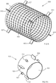
- Fig. 1A is an isometric view of an example fluid parameter meter 100.
- Fig. 1B is a cross section view looking down the central fluid flow axis of the example fluid parameter meter 100 of Fig. 1A .
- Fig. 1C is an oblique cross section view of the example fluid parameter meter 100 of Fig. 1A .
- Fig. 1D is a close up view of the example electromagnetic driver shown in Fig. 1C .
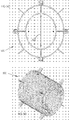
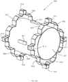
- Fig. 2A is an isometric view of an example sensor element assembly 200.
- Fig. 2B is a cross section view looking down the central fluid flow axis of the example sensor element assembly 200 shown in Fig. 2A .
- Fig. 2C and 2D are two views of an example sensor element assembly 200 shown as finite element analysis deflected shapes due to radial mode vibration.
- An example fluid parameter meter 100 includes flanges 103 and 104 which, and for this example are standard 6 inch 150 pound ANSI pipe flanges. Flanges 103 and 104 are welded to outer conduit 102 which is a 6 inch pipe. Also mounted in association with the outside of outer conduit 102 is electronics housing 108 which holds the control electronics 1401 through 1405 for meter 100. Also mounted in association with outer conduit 102 are magnet-coil assemblies 105A and 105B, and 106A and 106B, and wire conduits 107 for conveying electrical wires.
- a temperature sensor 113 is mounted in association with outer conduit 102.
- the temperature sensor may be a platinum RTD (resistive thermal device) in a thermal well arrangement for determining fluid temperature in a pipe.
- Temperature sensor 113 is configured to acquire an accurate temperature of any fluid inside of outer conduit 102.
- temperature sensor 113 may be provided for reporting fluid temperature to the meter user, and for compensating for temperature related material property changes in sensor element assembly 200.
- sensor element assembly 200 is mounted inside of outer conduit 102, as shown in detail in Fig. 2A and 2D .
- Sensor element assembly 200 is comprised of sensor element 201 which is a round steel tube of 4 inch diameter, .06 inch wall thickness, and 6 inches long.
- Mounting flexures 202 through 205 are also made of steel in the shape of thin walled flexural fins approximately 0.5 inches by 0.6 inches by .06 inches thick, and are mounted by brazing or welding toward the lower right (proximal) end of sensor element 201 of Fig. 2A , and along the sides of sensor element 201 on minimum vibration nodes.
- Mounting flexures 202 through 205 are aligned at 45, 135, 225, and 315 degrees respectively, around the circumference of sensor element 201.
- Toward the opposite (distal) end of sensor element 201 are mounting flexures 206 through 209 (not all mounting flexures are visible in all views) which are similar to and aligned with mounting flexures 202 through 205 respectively.
- the sensor element assembly 200 has four permanent magnets 210 through 213, fixedly attached to the side of sensor element 201 about half way along its length, and at the peak displacement locations (antinodes) for the mode of vibration (not all magnets are visible in all views).
- magnets 210 through 213 may be samarium cobalt type magnets due to their strength and temperature stability.
- neodymium iron, alnico, or other magnetic materials may be provided. Still other magnets may be provided.
- Permanent magnets 210 through 213 are aligned at 0, 90, 180 and 270 degrees respectively, around the circumference of sensor element 201. Permanent magnets 210 through 213 can be interchangeably provided for either causing requisite vibration, or for sensing the vibration thus caused as further explained hereinafter.
- sensor element 201 is a short straight section of relatively thin walled uniform tubing made of metal such as a corrosion resistant 300 series stainless steel, or a hardened type of metal such as 410 stainless steel, or PH 17-4, or 4340 steel. Non-metals can also be provided for this purpose such as ceramics, plastics, reinforced polymers, reinforced polyphenylene-sulfide, glass filled nylon, and the like.
- the length of sensor element 201 may be selected depending on desired vibration characteristics. In an example, the length is generally about one or two diameters in length or shorter, and circular in cross sectional shape. Fig.
- outer conduit 102 may be a round stainless steel pipe, although other shapes may also be implemented.
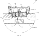
- Fig. 1D shows a close up cross section view of magnet-coil assembly 105A.
- Magnet-coil assembly 105A is comprised of permanent magnet 210 which is fixedly attached to and moves with the vibration of sensor element 201, and is protected from abrasive fluids by magnet guard 114 which may be made of a hard abrasive resistant material such as 410, 440, or 17-4 type stainless steel.
- Magnet guard 114 can be a simple tubular sleeve, but may also be a more hydrodynamic configuration as shown, and such as magnet guard 906 of Fig. 9A .
- Permanent magnet 210 causes magnetic field 115 to emanate therefrom, and pass through the wall of outer conduit 102, through armature 116, and through electrical coil 117.
- Electrical coil 117 is held in place by an interconnecting printed circuit board 118 and by fastener 119.
- armature 116 enhances the magnitude and direction of magnetic field 115, for example, if it is made of a magnetically permeable material such as carbon steel or 400-series stainless steel or the like.
- magnet coil assemblies 105A, 105B, 106A, and 106B are all constructed in the same way as just described for magnet coil assembly 105A, therefore each magnet coil assembly can be provided either as a vibration driver or as a vibration sensor and are therefore interchangeable.
- the mode of vibration for this example causes elliptical deflections of the sensor element 201 cross sectional shape as shown in Fig. 2C and 2D , diametrically opposite magnet coil assemblies can be electrically connected together to work as a pair.
- magnet coil assemblies 105A and 105B are electrically connected and work as one vibration sensor as shown in electrical schematic 1400 of Fig. 14 where electrical signals from magnet coil pair 105A and 105B supply a vibration related signal to amplifier 1401.
- magnet coil assemblies 106A and 106B can be electrically connected as a pair and work as one vibration driver as shown in Fig. 14 where amplifier 1402 supplies electrical excitation to magnet coil assemblies 106A and 106B.
- Fig. 14 also shows control module 1404 which receives vibration signals from amplifier 1401, and thereby controls amplifier 1402 to supply the requisite vibration forces to maintain a prescribed vibration mode and amplitude.
- Temperature Sensor 113 is also represented in electrical schematic 1400 and is also connected to control module 1404 via amplifier 1403 to deliver fluid temperature related signals thereto.
- control module 1404 uses vibration signals and temperature signals to determine output fluid parameters 1405 such as fluid density, viscosity, temperature, and other calculated results such as net percentage oil, pounds of propant added, gas volume fraction, or others.
- output fluid parameters 1405 such as fluid density, viscosity, temperature, and other calculated results such as net percentage oil, pounds of propant added, gas volume fraction, or others.
- the determination of these calculated results may also involve user input or assumed values such as water density, propant density, or others.
- Ambient vibration on sensor element assembly 200 causes an electrical signal in magnet coil assemblies 105A and 105B which is amplified by amplifier 1401 and passed along to control module 1404.
- Control module 1404 creates an output signal related to the vibration that is detected by magnet coil assemblies 105A and 105B.
- This output signal usually a sine wave, is amplified by amplifier 1402 and converted to a current of the appropriate phase and amplitude to reinforce the vibration just detected.
- the current thus created passes through magnet coil assemblies 106A and 106B thereby causing forces on sensor element assembly 200 to reinforce the desired vibration shape 214.
- the amplitude of the vibration shape 214 on sensor element assembly 200 may increase until it reaches a specified amplitude as determined by control module 1404. Once the specified amplitude is achieved, the amplification from amplifier 1402 is reduced to a level to maintain the specified vibration shape 214 amplitude. This vibration amplitude is maintained during normal operation and while the desired fluid parameters are determined.
- the period of oscillation is determined and squared by control module 1404.
- the period squared value is a representation of fluid density or specific gravity.
- Fig. 13 is graph 1300 of four different fluid specific gravities, plotted against their vibration period squared value.
- Graph 1300 shows a general linear relationship between vibration period squared and fluid specific gravity. This graph 1300 can therefore be reduced to an equation for control module 1404 to calculate any fluid's specific gravity based on the vibration period.
- each meter is calibrated at the factory to determine the equation of graph 1300 by testing the meter on two or more fluids such as air and water.
- the equation to calculate fluid density based on vibration period can also involve compensation values based on temperature and viscosity or others.
- the power or force to maintain a prescribed level, or velocity, or amplitude of vibration is determined by control module 1404 as a representation of fluid viscosity.
- the force to cause sensor element vibration, divided by the velocity of the resulting vibration is proportionally related to fluid damping or viscosity.
- the RTD 113 is normally a platinum type thin film or wire wound type sensor and circuit module 1403 is a commercial integrated circuit that supplies RTD 113 with a small current and measures the resistance of the RTD and converts that resistance to a temperature signal which is supplied to control module 1404. This is accomplished by application of the Callendar Van Dusen equation and there are many commercially available electronic modules available for this purpose.
- the fluid density is determined by the method earlier described. Using a user supplied density of the propant, and a user supplied or assumed density of the fluid mixed with the propant, the PPA can thereby be determined as a function of the two known densities, and the measured density of the mixed fluid in the meter.
- the percentage of oil in a mixture of water and oil "net oil” can be determined.
- the net-oil percentage can be determined in an example, as a function of the measured density of the mixture, and the user specified or assumed density of the water.
- gas volume fraction of a mixture of gas and fluid
- GVF gas volume fraction
- Sensor Element 201 is 6" long, 4" diameter, .06" wall thickness, 316 SS.
- the Mounting Flexures are 202-209: .5" wide, .6" tall, .06" thick, 316 SS.
- the Magnets are 210-213: .5" diameter .5" long, Samarium Cobalt.
- Density Results are plotted in Fig. 13 , line 1300 and show a linear relationship between fluid specific gravity (SG) and vibration period squared (VP ⁇ 2). Test results are shown in Table 1. Fluid SG Frequency (Hz) VP ⁇ 2 Air 0.001 465 4.62e-6 Water 1.00 226 1.96e-5 Fracking Fluid 1.4 196 2.6e-5 Zinc Bromide 2.2 160 3.9e-5
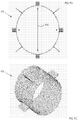
- Fig. 3A is an isometric view of another example sensor element assembly 300 having six mounting flexures at each end and six transducer magnets.
- Fig. 3B and 3C are two views of an example sensor element assembly 300 shown as finite element analysis deflected shapes due to radial mode vibration.
- Fig. 3A is another example sensor element assembly 300.
- Sensor element assembly 300 is similar to sensor element assembly 200 except that instead of having 4 mounting flexures at each end of the sensor element assembly 200, sensor element assembly 300 has six mounting flexures 302 and 303 at each end, and 6 magnets 304 at the mid length position. Having six mounting flexures at each end 302 and 303, and six magnets 304 allows sensor element assembly 300 to vibrate in a higher order mode of vibration where the cross section vibration shape 305 is more triangular as shown in Fig. 3B and 3C . In an example, the vibration shape 305 is uniform along the length of sensor element assembly 300.
- sensor element assembly 300 The operation of sensor element assembly 300 is similar to that of sensor element assembly 200 earlier described, except that six magnets 304 are provided for driving and sensing the vibration motion 305, three for driving and three for sensing the vibration motion 305.
- six magnets 304 are provided for driving and three magnets 304 are provided for sensing so that the driving forces are balanced. It is noted however, that other combinations of driving and sensing magnets may be provided.
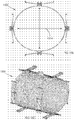
- Fig. 4A is an isometric view of another example sensor element assembly 400 having eight mounting flexures at each end and eight transducer magnets.
- Fig. 4B and 4C are two views of an example sensor element assembly 400 shown as finite element analysis deflected shapes due to radial mode vibration.
- Fig. 4A is another example sensor element assembly 400.
- Sensor element assembly 400 is similar to sensor element assembly 300, except that instead of having six mounting flexures at each end of the sensor element assembly 300.
- Sensor element assembly 400 has eight mounting flexures 402 and 403 at each end, and 8 magnets 404 at the mid length position. Having eight mounting flexures 402 and 403, and eight magnets 404 allows sensor element assembly 400 to vibrate in a higher mode of vibration where the cross section vibration shape 405 is more rectangular as shown in Fig. 4B and 4C . In an example, the vibration shape 405 is uniform along the length of sensor element assembly 300.
- sensor element assembly 400 is similar to that of sensor element assembly 200 earlier described, except that eight magnets 404 are provided for driving and sensing the vibration motion 405, four for driving and four for sensing the vibration motion 405. In this example, four magnets 404 are provided for driving and four magnets 404 are provided for sensing so that the driving forces are balanced. It is noted, however, that other combinations of driving and sensing magnets may be provided.
- Fig. 5A is an isometric view of another example fluid parameter meter, where the sensor element assembly 500 has two sensor element conduits arranged in parallel as a concentric pair.
- Fig. 5B is a view down the central fluid flow axis of the example fluid parameter meter shown in Fig. 5A .
- Fig. 5C and 5D are two views of an example sensor element assembly 500 shown as finite element analysis deflected shapes due to radial mode vibration.
- the fluid parameter meter has two concentric sensor elements 501 and 502 which are round straight metal conduits.
- Outer sensor element 501 has four mounting flexures 503 through 506 fixedly attached to the near (proximal) end and four mounting flexures 507 through 510 (507 not visible in this view) fixedly attached to the far (distal) end.
- Mounting flexures 503 through 510 may also be fixedly attached to the inside of an outer conduit 519.
- Magnets 521 through 524 are also fixedly attached to the outer sensor element 501 at its mid length position, and circumferentially rotated by 45 degrees from the mounting flexures 503 through 510 so that they coincide with vibration antinodes.
- inner sensor element 502 is fixedly attached to mounting flexures 511 through 518 which are in circumferential alignment with magnets 521 through 524 so that they coincide with vibration antinodes of outer sensor element 501.
- Sensor element assembly 500 can be substituted for sensor element assembly 200 as earlier described, and operated in the same way.
- An advantage of having two concentric sensor elements 501 and 502 connected by mounting flexures 511 through 518 is that both sensor elements 501 and 502 vibrate in unison 525 as shown in Fig. 5C and 5D .
- This concentric arrangement minimizes velocity profile effects because more of the fluid is vibrated at the amplitude of the sensor elements, especially in the annular space between the sensor elements 501 and 502.
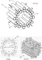
- Fig. 6A is an isometric view of another example fluid parameter meter, where the sensor element assembly 600 has of a plurality of sensor element conduits arranged in parallel clustered around a central sensor element.
- a plurality of smaller sensor elements 603 are arranged around a central sensor element 601.
- mounting flexures 602 may be fixedly attached to an outer conduit (not shown). No magnets are shown on this example for visual clarity but may be provided as described on earlier examples.
- Fig. 6B and 6C are two views of an example sensor element assembly 600 shown as finite element analysis deflected shapes due to radial mode vibration.
- An advantage to sensor element assembly 600 is that it reduces velocity profile effects because the smaller sensor elements 603 capture and vibrate the fluid at the same vibration amplitude 620 as the sensor element 601 thereby vibrating more of the fluid than may be vibrated by sensor element 601 alone.
- sensor element assembly 600 may have 4 magnets attached at the mid length position (not shown) at the antinodes of vibration 620, and may be operated as earlier described for sensor element assembly 200.
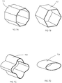
- Fig. 7A through 7D show example sensor element shapes that are non-circular.
- Figure 7A shows an example of an octagonal sensor element 701.
- Figure 7B shows an example of a hexagonal sensor element 702.
- Figure 7C shows an example of a four-lobed clover leaf shaped sensor element 703.
- Figure 7D shows an example of an oval or elliptical shaped sensor element 704. Any of the shapes of sensor elements 701 through 704 and others can be used.
- Fig. 8 is an isometric view of another example sensor element assembly 800 having a pattern of openings or holes in sensor element.
- the sensor element assembly 800 includes sensor element 801, which is a round straight section of metal conduit.
- Sensor element 801 includes hole pattern 802 allowing fluid to flow between the inside and the outside of sensor element 801.
- Sensor element 801 also includes mounting flexures 803 through 810 which are metal fins of the same approximate thickness as is sensor element 801 and are arranged in the same manner and fixedly attached in the same manner as earlier described for sensor element assembly 200. No magnets are shown for visual clarity, but may be provided as in earlier examples.
- An advantage of having hole pattern 802 in sensor element 801 is that it allows fluid flow between the inside and the outside of sensor element 801 and thereby reduces wall effects. As the annular space between a sensor element and an outer conduit becomes smaller, fluid becomes more trapped there between. This entrapment of fluid inhibits the fluid's ability to move and accelerate under the influence of a vibrating sensor element. This inhibiting effect changes the vibrational frequency and damping characteristics of the sensor element assembly, and also changes the meters sensitivity to measuring fluid density and viscosity. Making the annular space large is sometimes not practical due to space constraints in a particular configuration, therefore by adding hole pattern 802, the vibration inhibiting affect is minimized or eliminated.
- Fig. 9A is an isometric view of an example sensor element assembly 900 having four mounting flexures arranged at the mid length position of the sensor element, and having hydro-dynamically shaped magnet guards to protect the magnets.
- Sensor element assembly 900 is shown including sensor element 901, which is a round straight tubular sensor element made of metal and includes four mounting flexures 902 through 905 (902 not visible in this view).
- Mounting flexures 902 through 905 are located at the mid length position of sensor element 901 and are mounted along its node areas where vibration amplitude is minimal.
- Magnet assemblies 906 through 909 (908 is not visible in this view) are configured having hydro-dynamically shaped magnet guards to protect them from abrasion.
- Magnet assemblies 906 through 909 are circumferentially rotated 45 degrees from the mounting flexures 902 through 905 so that they are located in anti-node areas of maximum deflection. In operation, sensor element assembly may be operated in the same way as was earlier described for sensor element assembly 200.
- Fig. 9B and 9C are two views of an example sensor element 900 assembly shown as finite element analysis deflected shapes due to radial mode vibration.
- Fig. 9B and 9C show a finite element analysis plot of how the vibration shape 920 of sensor element assembly 900 is elliptical and uniform along its length.
- Fig. 10 is a close up cross section view of an example sensor element 1000 having a pattern where the openings are specifically shaped to induce fluid flow there through.
- Sensor element 1000 includes hole pattern 1001 where the holes are specifically shaped in such a way to induce fluid flow 1004 to pass through from the outside in through hole 1002 and from the inside out through hole 1003 as shown in Fig. 10 .
- This example configuration can decrease wall effects and particle slippage and velocity profile effects, especially in low viscosity fluids because it induces more particle-tube interaction.
- the shape of the holes in hole pattern 1001 can be angled as shown in Fig. 10 by laser cutting, or punching, or machining, or other forming methods.
- Fig. 11 is an example wear guard 1100 configured to protect the leading edges of a sensor element assembly from abrasive wear.
- Abrasive wear was earlier described as most severe on the leading edges of the sensor element and on the mounting flexures. Therefore, an example wear guard 1100 is shown having the same cross sectional shape perpendicular to the direction of fluid flow as does the sensor element assembly it is to guard.
- Wear guard 1100 is therefore comprised of guard element 1101, and guard mounting supports 1102 through 1105 all of which have a similar size and shape as a sensor element assembly it is configured to guard.
- the wear guard 1100 takes the brunt of the direct impingement of the abrasive wear and protects the leading edges of any sensor element assembly located downstream.
- Fig. 12 is an oblique view of an example sensor element assembly and wear guard 1100 shown in alignment for protecting the sensor element assembly from abrasive wear.
- Fig. 12 shows the just described assembly of wear guard 1100 and sensor element assembly 200.
- Sensor element 201 is coaxially aligned with guard element 1101 and spaced apart to leave a gap 1201 there between.
- Fig. 13 is a graph illustrating a relationship between vibration period squared versus fluid specific gravity for an example fluid parameter meter, to determine fluid density from vibration period. The values given in Table 1 described previously are plotted along curve 1300 showing the generally linear relationship between vibration period squared, and fluid specific gravity SG as was earlier described.
- Fig. 14 is a block diagram showing signal processing for an example fluid parameter meter.
- the function of signal processing block diagram 1400 was earlier described with reference to fluid parameter meter 100.
- Signal processing diagram 1400 is representative of many of the sensor embodiments previously described and can be used with any of them with some variations for having more driving and sensing transducers for some of the examples shown.
- Fig. 15A is an isometric view of an example sensor element assembly 1500, where the mounting flexures are arranged tangent to the sensor element and are attached to the sensor element on anti-nodal areas.
- Example sensor element assembly 1500 includes sensor element 1501, and mounting flexures 1502 through 1509 (1509 is not visible in this view) are mounted generally tangent to the surface of sensor element 1501 on the anti-node areas; rather than being mounted radially in node areas as was the case for the previous examples.
- Mounting flexures 1502 through 1509 have a thickness perpendicular to the direction of fluid flow similar to sensor element 1501 to minimize obstruction to flow.
- Mounting flexures 1502 through 1509 also include bends to facilitate mounting and to facilitate a specified stiffness.
- An advantage of arranging the mounting flexures 1502 through 1509 tangentially as shown, is that the natural modes of vibration can be less influenced by the stiffness of the mounting flexures, and the stress in the mounting flexures 1502 through 1509 can be configured to have lower values because they can be made to be any length regardless of the width of the annular space between the sensor element 1501 and the outer conduit in which it may be mounted (not shown).
- Magnets 1510 through 1513 are hydro-dynamically shaped to prevent abrasive wear.
- Fig. 15B and 15C are two views of the example sensor element assembly of Fig. 15A shown as Finite Element deflected shapes from a selected mode of vibration.
- Fig. 15B and 15C are finite element analysis deflected shape predictions for an example mode of vibration of sensor element assembly 1500 and show the vibration deflected shape 1514.
- Sensor element assembly 1500 can be provided as a direct replacement for sensor element assembly 200 and functions in the same way as previously described.
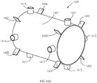
- Fig. 16A is an isometric view of another example fluid parameter meter, where the sensor element assembly has sets of transducer magnets arranged near both ends of sensor element to facilitate multiple modes of vibration and mode shapes that invert along the length of the sensor element.
- Fig. 16B and 16C are two views of the example sensor element assembly shown as Finite Element Analysis deflected shapes from a selected mode of vibration.
- Fig. 16D and 16E are two views of the example sensor element assembly shown as Finite Element Analysis deflected shapes from a selected mode of vibration, where the radial mode shape inverts along the length of the sensor element.
- Fig. 16A shows another example where a set of four magnets 1610 through 1613 are arranged near the lower right proximal end of sensor element 1601, and another set of four magnets 1614 through 1617 are arranged near the upper left distal end of sensor element 1601.
- This arrangement allows for modes of vibration that invert in shape along the length of sensor element 1601, as well as modes that do not invert along the length of sensor element 1601.
- Each magnet 1610 through 1617 is accompanied by a corresponding coil not shown (for visual clarity) in Fig. 16A through 16E (but shown in Fig. 17 as having the same magnet number and an "A" designation thereafter).
- Coils 1610A and 1612A are wired together to act as one coil to sense radial mode shape vibration at the proximal end of sensor element 1601.
- Coils 1614A and 1616A are wired together to act as one coil to sense radial mode shape vibration at the distal end of sensor element 1601.
- Fig. 16B and 16C are finite element deflected shape predictions of sensor element assembly 1600 where the selected mode shape motion 1618 is elliptical in cross section shape and is uniform along the length of sensor element 1601.
- Fig. 16D and 16E are finite element deflected shape predictions of sensor element assembly 1600 where the selected mode shape motion 1619 is elliptical in cross section shape and is not uniform along the length of sensor element 1601, but instead the deflection shape 1619 inverts once from the distal end to the proximal end of sensor element 1601.
- This mode shape can causes Coriolis forces along the length of sensor element 1601 which in turn cause Coriolis deflections similar to deflected shape 1618. This feature measures fluid flow rate using the Coriolis effect as next described.
- Fig. 17 is a block diagram showing signal processing for an example fluid parameter meter, where fluid flow rate is determined along with other fluid parameters. Temperature sensor 1713 is shown in Fig. 17 but not in Fig. 16A through 16E for visual clarity. Temperature sensor 1713 along with amplifier 1703 measures the temperature of the fluid flowing in and around sensor element assembly 1600 and relays that signal to control module 1704 for thermal affect compensation and for reporting as a temperature output signal 1705.
- the circuit shown in Fig. 17 may be provided in conjunction with sensor element assembly 1600.
- vibration shape 1619 is induced to vibrate by amplifier 1702 driving magnet coil pairs 1611(A) and 1613(A) together in phase with each other, but out of phase by 180° from driving magnet coil pairs 1615(A) and 1617(A).
- signals from magnet coil pairs 1610(A) and 1612(A) are sensed by amplifier 1701 representing the radial motion at the proximal end of sensor element 1601.
- signals from magnet coil pairs 1614(A) and 1616(A) are sensed by amplifier 1701 representing the radial motion at the distal end of sensor element 1601.
- control module 1704 receives signals from magnet coil pairs 1604 to provide both drive control signals back to driving amplifier 1702 for drive control, and to determine fluid parameters such as fluid density, viscosity, temperature, flow rate, and other calculated results such as PPA, GVF, Net-oil, and others.
- Control module 1704 calculates the phase or time difference between the distal end motion and the proximal end motion of sensor element 1601. This phase difference can be proportionally related to the flow rate of fluid passing through sensor element assembly 1600.
- the same methods may be applied that were previously discussed for the example of Fig. 1 .
- the calculated result of Reynolds Number may be determined as being a function of the measured parameters of flow rate velocity, density and viscosity, and the pipe diameter, which are all known or measured by the meter.
- the calculated result of kinematic viscosity can be calculated from the absolute, sometimes called the (dynamic) viscosity and the fluid density which is measured by the meter.
- Fig. 18A is an isometric view of an example sensor element assembly 1800, where the mounting flexures are arranged tangent to the sensor element and are attached to the sensor element on nodal areas.
- Fig. 18B and 18C are two views of the example sensor element assembly of Fig. 18A , shown as Finite Element deflected shapes from a selected mode of vibration.
- the example sensor element assembly 1800 includes sensor element 1801, and mounting flexures 1802 through 1809 are mounted generally tangent to the surface of sensor element 1801 along their mid-spans, and on the nodal areas of sensor element 1801 for selected modes of vibration.
- Mounting flexures 1802 through 1809 have a thickness perpendicular to the direction of fluid flow similar to sensor element 1801 to minimize obstruction to flow.
- Mounting flexures 1802 through 1809 can include bends to facilitate mounting and to facilitate a specified stiffness.
- Mounting flexures 1802 through 1809 are fixedly attached to mounting blocks 1814 through 1821 (mounting block 1821 not visible in this view) at their distal ends.
- mounting blocks 1814 through 1824 are configured to allow mounting the entire sensor assembly 1800 to the outer conduit (not shown in this view).
- Mounting blocks 1814 through 1824 can be fixedly attached to an outer conduit by any means including brazing, welding, adhesion, or by bolting through holes as is shown in this example.
- An advantage of arranging the mounting flexures 1802 through 1809 as shown, is that the natural modes of vibration can be less influenced by the properties of the mounting flexures, and the stress in the mounting flexures 1802 through 1809 can be configured to have specific or lower values because they can be made to be any stiffness regardless of the width of the annular space between the sensor element 1801 and the outer conduit in which it may be mounted (not shown).
- armatures 1810 through 1813 magnetically couple sensor assembly 1801 to driving and sensing electro-magnetic coils (not shown in this view) outside of an outer conduit.
- Armatures 1810 through 1813 may be made of magnetically permeable material such as carbon steel, type 410 stainless steel, type 430 stainless steel, Carpenter Steel Corporation High Permeability Alloy 49, HyMu 80 alloy, transformer iron, silicon iron, ferrite, and the like. Armatures 1810 through 1813 may be fixedly attached to sensor element 1801 by any method including brazing, welding, adhesion, fusion bonding, and the like.
- armatures 1810 through 1813 may not be provided because the wall of sensor element 1801 can function as an armature thereby magnetically coupling with driving and sensing coils outside of an outer conduit (not shown).
- Fig. 18B and 18C are finite element analysis deflected shape predictions for an example mode of vibration of sensor element assembly 1800 and show the vibration deflected shape motion 1822.
- Sensor element assembly 1800 may be a direct replacement for sensor element assembly 200 and may function in the same way as previously described.
- MEMS Micro Electro Mechanical Sensors
- MEMS may be incorporated into the meter that provide complementary fluid process variable measurements, which may be used either individually and/or in combination with existing meter process fluid measurements. Resulting in either all new process meter fluid outputs and/or compensations that may improve existing meter process fluid outputs.
- These MEMS transducers may include but are not limited to pressure, pH, ultrasonic, acceleration, etc.
Landscapes
- Physics & Mathematics (AREA)
- Fluid Mechanics (AREA)
- General Physics & Mathematics (AREA)
- Measuring Volume Flow (AREA)
Claims (14)
- Dispositif de mesure de paramètre de fluide (100) pour mesurer au moins un paramètre d'un fluide, le dispositif de mesure (100) comprenant :un conduit externe (102) ;un ensemble d'éléments de capteur (200) qui est disposé dans le conduit externe (102) et qui a au moins un élément de capteur uniforme et droit (201) avec un intérieur ouvert pour transporter le fluide à l'intérieur de l'ensemble d'éléments de capteur (200) ;au moins un dispositif d'entraînement de vibration (105A, 105B, 106A, 106B) pour faire vibrer l'ensemble d'éléments de capteur (200) ; etau moins un capteur de vibration (105A, 105B, 106A, 106B) pour détecter la vibration de l'ensemble d'éléments de capteur (200) ;caractérisé en ce que :
au moins un élément de flexion de montage (202 - 205) qui est relié de manière fixe à l'ensemble d'éléments de capteur (200) et au conduit externe (102) pour relier l'ensemble d'éléments de capteur (200) au conduit externe (102), ledit au moins un élément de flexion de montage (202 - 205) étant configuré de manière à permettre à l'ensemble d'éléments de capteur (200) de vibrer sous une forme naturelle en mode radial de vibration. - Dispositif de mesure (100) selon la revendication 1, dans lequel le conduit externe (102) sert à transporter le fluide ; et
l'ensemble d'éléments de capteur (200) est séparé du conduit externe (102) par un espace annulaire essentiellement uniforme configuré de manière à transporter le fluide à l'extérieur de l'ensemble d'éléments de capteur (200). - Dispositif de mesure (100) selon la revendication 2, comprenant en outre :une électronique de commande (1401 - 1405) qui coopère avec le capteur de vibration (105A, 105B, 106A, 106B) et le dispositif d'entraînement de vibration (105A, 105B, 106A, 106B) pour faire vibrer de manière contrôlée l'ensemble d'éléments de capteur (200) dans au moins un mode prescrit de vibration, à une amplitude prescrite ;l'électronique de commande (1401 - 1405) qui peut fonctionner de manière à produire au moins un signal de sortie issu de l'électronique de commande (1401 - 1405) et proportionnellement lié audit au moins un paramètre d'un fluide.
- Dispositif de mesure (100) selon la revendication 3, dans lequel ledit un paramètre d'un fluide est sélectionné parmi au moins l'un de :la densité de fluide, la concentration massique, la concentration volumique, le nombre de Reynolds ;la viscosité de fluide, absolue et cinématique ;le débit de fluide ; etle résultat calculé de fluide.
- Dispositif de mesure (100) selon la revendication 3, dans lequel le dispositif d'entraînement de vibration (105A, 105B, 106A, 106B) et le capteur de vibration (105A, 105B, 106A, 106B) incluent chacun l'un de :un aimant permanent (210 - 213) qui est monté en association avec l'ensemble d'éléments de capteur (200) et une bobine électrique (117) qui est montée en association avec le conduit externe (102) ; etune armature (116) qui est montée en association avec l'ensemble d'éléments de capteur (200) et une bobine électrique (117) qui est montée en association avec le conduit externe (102).
- Dispositif de mesure (100) selon la revendication 2 ou 3, incluant en outre un capteur de température (113), dans lequel le capteur de température (113) fournit, à l'électronique de commande (1401 - 1405), un signal relatif à la température qui est proportionnellement lié à la température de l'ensemble d'éléments de capteur (200).
- Dispositif de mesure (100) selon la revendication 2 ou 3, comprenant en outre une protection contre l'usure (1100) qui est associée à l'ensemble d'éléments de capteur (200) pour protéger des dommages l'ensemble d'éléments de capteur (200).
- Dispositif de mesure (100) selon la revendication 2 ou 3, dans lequel l'élément de capteur (201) inclut en outre des ouvertures pour que le fluide circule entre l'intérieur de l'élément de capteur (201) et l'espace annulaire.
- Dispositif de mesure (100) selon la revendication 8, dans lequel les ouvertures sont formées de manière à induire le fluide à y circuler à travers.
- Dispositif de mesure (100) selon la revendication 2 ou 3, dans lequel l'ensemble d'éléments de capteur (200) est composé de l'un parmi : une pluralité d'éléments de capteur disposés concentriquement, et une pluralité d'éléments de capteur disposés en parallèle.
- Dispositif de mesure (100) selon la revendication 2 ou 3, dans lequel ledit au moins un mode prescrit de vibration inverse sa forme au moins une fois le long de la longueur de l'ensemble d'éléments de capteur (200).
- Dispositif de mesure (100) selon la revendication 2, lequel est capable de fonctionner conjointement avec l'électronique de commande, dans lequel ledit un paramètre d'un fluide est sélectionné parmi la densité de fluide, la viscosité de fluide, le débit de fluide et le résultat calculé de fluide.
- Dispositif de mesure (100) selon la revendication 2, lequel le dispositif d'entraînement de vibration (105A, 105B, 106A, 106B) inclut un aimant permanent (210 - 213) qui est monté en association avec l'ensemble d'éléments de capteur (200), et une bobine électrique (117) qui est montée en association avec le conduit externe (102).
- Dispositif de mesure (100) selon la revendication 2, dans lequel le capteur de vibration (105A, 105B, 106A, 106B) inclut un aimant permanent (210 - 213) qui est monté en association avec l'ensemble d'éléments de capteur (200), et une bobine électrique (117) qui est montée en association avec le conduit externe (102).
Applications Claiming Priority (2)
| Application Number | Priority Date | Filing Date | Title |
|---|---|---|---|
| US201462097209P | 2014-12-29 | 2014-12-29 | |
| PCT/US2015/067710 WO2016109447A1 (fr) | 2014-12-29 | 2015-12-28 | Capteur et dispositif de mesure de paramètre de fluide |
Publications (3)
| Publication Number | Publication Date |
|---|---|
| EP3215812A1 EP3215812A1 (fr) | 2017-09-13 |
| EP3215812A4 EP3215812A4 (fr) | 2018-07-25 |
| EP3215812B1 true EP3215812B1 (fr) | 2020-10-07 |
Family
ID=56163778
Family Applications (1)
| Application Number | Title | Priority Date | Filing Date |
|---|---|---|---|
| EP15876115.5A Active EP3215812B1 (fr) | 2014-12-29 | 2015-12-28 | Capteur et dispositif de mesure de paramètre de fluide |
Country Status (3)
| Country | Link |
|---|---|
| US (1) | US9752911B2 (fr) |
| EP (1) | EP3215812B1 (fr) |
| WO (1) | WO2016109447A1 (fr) |
Families Citing this family (14)
| Publication number | Priority date | Publication date | Assignee | Title |
|---|---|---|---|---|
| WO2016109451A1 (fr) | 2014-12-29 | 2016-07-07 | Concentric Meter Corporation | Transducteur électromagnétique |
| US10126266B2 (en) | 2014-12-29 | 2018-11-13 | Concentric Meter Corporation | Fluid parameter sensor and meter |
| US10871432B1 (en) * | 2016-08-26 | 2020-12-22 | Rheonics Gmbh | Tubular sensors for inline measurement of the properties of a fluid |
| WO2018075075A1 (fr) * | 2016-10-21 | 2018-04-26 | Halliburton Energy Services, Inc. | Procédés et systèmes de détermination de densité de fluide par détection acoustique distribuée |
| DE102018102831A1 (de) | 2017-10-05 | 2019-04-11 | Endress+Hauser Flowtec Ag | Meßwandler für ein vibronisches Meßsystem sowie damit gebildetes vibronisches Meßsystem |
| US10598531B2 (en) * | 2018-04-23 | 2020-03-24 | General Electric Company | Coriolis flow meter with multiple actuators arranged on a flow tube and driven in different planes |
| RU185539U1 (ru) * | 2018-09-13 | 2018-12-07 | Акционерное общество "Промышленная группа "Метран" | Узел крепления сенсоров в проточной части вихревого расходомера |
| DE102018133117A1 (de) | 2018-12-20 | 2020-06-25 | Endress+Hauser Flowtec Ag | Coriolis-Massendurchfluß-Meßgerät |
| CN113242960B (zh) | 2018-12-20 | 2024-05-14 | 恩德斯+豪斯流量技术股份有限公司 | 科里奥利质量流量计 |
| CN113196016B (zh) | 2018-12-21 | 2024-06-21 | 恩德斯+豪斯流量技术股份有限公司 | 具有磁场探测器的科里奥利质量流量计 |
| DE102019133610A1 (de) | 2019-12-09 | 2021-06-10 | Endress + Hauser Flowtec Ag | Vibronisches Meßsystem zum Messen eines Massestroms eines fluiden Meßstoff |
| DE102020127382A1 (de) | 2020-10-16 | 2022-04-21 | Endress+Hauser Flowtec Ag | Verfahren zum Überprüfen eines vibronischen Meßsystems |
| US12287252B2 (en) * | 2021-04-06 | 2025-04-29 | Hexagon Technology As | Multi-element sensor for monitoring composite structure |
| JP2024090372A (ja) * | 2022-12-23 | 2024-07-04 | 富士電機株式会社 | クランプオン式超音波流量計 |
Family Cites Families (303)
| Publication number | Priority date | Publication date | Assignee | Title |
|---|---|---|---|---|
| US1175586A (en) | 1915-06-26 | 1916-03-14 | Philip Beyler | Screen-door brace. |
| US2215566A (en) * | 1938-05-11 | 1940-09-24 | Bendix Aviat Corp | Sealing means for indicating instrument casings |
| US2340992A (en) | 1942-07-25 | 1944-02-08 | Westinghouse Electric & Mfg Co | Device for measuring viscosity of liquids |
| US3021711A (en) | 1957-05-10 | 1962-02-20 | Svenska Flygmotor Aktiebolaget | Device for measuring pressure or difference of pressure in fluids |
| US3164987A (en) | 1961-03-28 | 1965-01-12 | Bosch Arma Corp | Electrostatic vibration transducer |
| US3218851A (en) | 1961-05-24 | 1965-11-23 | Anatole J Sipin | Mass flowmeter systems |
| US3225588A (en) | 1962-03-06 | 1965-12-28 | Schlumberger Prospection | Densimetering systems |
| GB1175664A (en) | 1966-01-28 | 1969-12-23 | Solartron Electronic Group | Improvements in or relating to Methods of Measuring the Densities of Fluids and Apparatus therefor |
| GB1175586A (en) | 1967-07-26 | 1969-12-23 | Joram Agar | Measuring of Fluid Density |
| US3677067A (en) | 1970-08-20 | 1972-07-18 | Itt | Densitometer |
| US3741000A (en) | 1971-04-08 | 1973-06-26 | Itt | Vibration densitometer probe |
| GB1432165A (en) | 1973-07-16 | 1976-04-14 | Bell & Howell Co | Apparatus for determining the density of a fluid |
| US3984895A (en) | 1973-11-01 | 1976-10-12 | Fiber Controls Corporation | Density sensing and controlling equipment |
| US4015470A (en) | 1973-12-26 | 1977-04-05 | Trw Inc. | Flow measuring method and apparatus |
| US3956922A (en) | 1974-12-09 | 1976-05-18 | International Telephone And Telegraph Corporation | Densitometer probe shield and well |
| US4117716A (en) | 1974-06-17 | 1978-10-03 | Honeywell Inc. | Densitometer apparatus |
| GB1482988A (en) | 1974-08-08 | 1977-08-17 | Agar Instr | Method and apparatus for measuring the density of a dirty fluid |
| GB1521467A (en) | 1974-09-21 | 1978-08-16 | Solartron Electronic Group | Density transducer |
| US3981183A (en) | 1974-10-03 | 1976-09-21 | Automation Products, Inc. | Method and apparatus for measuring a physical property of a fluid material that varies nonlinearly relative to the density of the fluid |
| DE2501380C3 (de) * | 1975-01-15 | 1979-01-11 | Robert Bosch Gmbh, 7000 Stuttgart | Massendurchflußmesser für strömende Medien |
| US3967490A (en) | 1975-06-27 | 1976-07-06 | International Telephone And Telegraph Corporation | Vibration densitometer |
| US3958446A (en) | 1975-08-20 | 1976-05-25 | International Telephone And Telegraph Corporation | Discontinuity suppression apparatus for vibration densitometers |
| US3999421A (en) | 1975-10-06 | 1976-12-28 | Thomas J. Lipton, Inc. | Powder bulk density instrument |
| US4096745A (en) | 1976-02-13 | 1978-06-27 | Ilya Yakovlevich Rivkin | Method and apparatus for measuring mass flow rate of individual components of two-phase gas-liquid medium |
| CH609151A5 (fr) | 1976-03-30 | 1979-02-15 | Straumann Inst Ag | |
| US4020330A (en) | 1976-05-03 | 1977-04-26 | International Telephone And Telegraph Corporation | Densitometer |
| US4037459A (en) | 1976-06-28 | 1977-07-26 | International Telephone And Telegraph Corporation | Densitometer |
| JPS5922515Y2 (ja) | 1976-07-20 | 1984-07-05 | 横河電機株式会社 | 振動式密度計 |
| US4037460A (en) | 1976-07-29 | 1977-07-26 | International Telephone And Telegraph Corporation | Densitometer |
| US4037461A (en) | 1976-08-05 | 1977-07-26 | International Telephone And Telegraph Corporation | Probe and method of making the same |
| US4023400A (en) | 1976-08-23 | 1977-05-17 | International Telephone And Telegraph Corporation | Viscosimeter and/or densitometer |
| US4063448A (en) | 1976-08-25 | 1977-12-20 | Agar Instrumentation Inc. | Density meter coil assembly |
| US4064736A (en) | 1976-10-01 | 1977-12-27 | Tracy Ireland | Method and apparatus for measuring performance times of a shutter apparatus |
| US4041769A (en) | 1976-10-05 | 1977-08-16 | International Telephone And Telegraph Corporation | Densitometer |
| AT353039B (de) | 1976-11-29 | 1979-10-25 | Kratky Otto Dipl Ing Dr Dr H C | Vorrichtung zur messung der dichte |
| US4074562A (en) | 1977-01-13 | 1978-02-21 | Becton, Dickinson And Company | Method and apparatus for measuring fluid specific gravity |
| US4064738A (en) | 1977-02-07 | 1977-12-27 | International Telephone And Telegraph Corporation | Vibration densitometer |
| US4084425A (en) | 1977-05-11 | 1978-04-18 | International Telephone And Telegraph Corporation | Vibration densitometer |
| US4127028A (en) | 1977-06-07 | 1978-11-28 | Halliburton Company | Coriolis mass flow rate metering means |
| US4187721A (en) | 1977-07-25 | 1980-02-12 | S & F Associates | Method and structure for flow measurement |
| USRE31450E (en) | 1977-07-25 | 1983-11-29 | Micro Motion, Inc. | Method and structure for flow measurement |
| CH619043A5 (fr) | 1977-07-27 | 1980-08-29 | Straumann Inst Ag | |
| US4129031A (en) | 1977-09-16 | 1978-12-12 | General Electric Company | Immersible liquid densitometer |
| US4282742A (en) | 1977-09-28 | 1981-08-11 | International Telephone And Telegraph Corporation | Densitometer |
| US4262523A (en) | 1977-12-09 | 1981-04-21 | The Solartron Electronic Group Limited | Measurement of fluid density |
| US4135383A (en) | 1977-12-30 | 1979-01-23 | International Telephone And Telegraph Corporation | Vibration densitometer probe |
| US4193291A (en) | 1978-02-27 | 1980-03-18 | Panametrics, Inc. | Slow torsional wave densitometer |
| US4158959A (en) | 1978-03-02 | 1979-06-26 | Camco, Incorporated | Apparatus for measuring the physical properties of material |
| US4151743A (en) | 1978-06-28 | 1979-05-01 | International Telephone And Telegraph Corporation | Densitometer drive |
| GB2027539B (en) | 1978-08-09 | 1983-09-21 | Marconi Co Ltd | Measurement of the density of liquids |
| GB2027886B (en) | 1978-08-14 | 1983-02-02 | Solartron Electronic Group | Transducer for sensing a parameter of a fluid |
| US4192184A (en) | 1978-11-13 | 1980-03-11 | Halliburton Company | Mass flowmeter |
| JPS5589744A (en) | 1978-12-27 | 1980-07-07 | Terumo Corp | Liquid density measuring method of ultrasonic wave and its unit |
| US4217774A (en) | 1979-01-04 | 1980-08-19 | Joram Agar | Apparatus for measuring the value of a fluid variable |
| JPS5838738B2 (ja) | 1979-01-11 | 1983-08-25 | 横河電機株式会社 | 圧力計 |
| US4194385A (en) | 1979-01-17 | 1980-03-25 | International Telephone And Telegraph Corporation | Densitometer calibration method |
| US4215566A (en) | 1979-04-30 | 1980-08-05 | International Telephone And Telegraph Corporation | Densitometer with voltage driver |
| DK144044C (da) | 1979-05-10 | 1982-05-17 | Danfoss As | Ultralydmaaleprobe til brug ved akustisk maaling af vaeskers massefylde |
| GB2058348B (en) | 1979-06-04 | 1983-09-07 | Agar Instr | Apparatus for use in the measurement of a variable |
| US4265125A (en) | 1979-08-02 | 1981-05-05 | Mahany Richard J | Flowmeter method and apparatus |
| DE3039438A1 (de) | 1979-11-06 | 1981-08-27 | The Solartron Electronic Group Ltd., Farnborough, Hampshire | Fluessigkeitsdichtewandler |
| US4275585A (en) | 1979-11-21 | 1981-06-30 | General Electric Company | Vibrator type densitometer |
| GB2063821B (en) | 1979-11-26 | 1983-04-20 | Univ Queensland | Sampling apparatus |
| GB2071848B (en) | 1980-02-28 | 1984-05-23 | Marconi Co Ltd | Mass flow measurement device |
| US4283936A (en) | 1980-03-17 | 1981-08-18 | International Telephone And Telegraph Corporation | Vibration densitometer assembly |
| US4349881A (en) | 1980-07-14 | 1982-09-14 | International Telephone And Telegraph Corporation | Vibration instruments |
| US4345456A (en) | 1980-09-15 | 1982-08-24 | International Telephone And Telegraph Corporation | Densitometer |
| US4429564A (en) | 1981-01-23 | 1984-02-07 | Yokogawa Hokushin Electric Corporation | Vibration type density meter |
| US4449414A (en) | 1981-05-21 | 1984-05-22 | Smiths Industries Public Limited Company | Fluid-responsive apparatus |
| DE3124506A1 (de) | 1981-06-23 | 1983-01-05 | Robert Bosch Gmbh, 7000 Stuttgart | Massendurchflussmesser und auswerteschaltung dazu |
| US4411161A (en) * | 1981-08-10 | 1983-10-25 | International Telephone & Telegraph Corporation | Mass flowmeter or the like |
| US4445389A (en) | 1981-09-10 | 1984-05-01 | The United States Of America As Represented By The Secretary Of Commerce | Long wavelength acoustic flowmeter |
| JPS58137726A (ja) | 1982-02-12 | 1983-08-16 | Yokogawa Hokushin Electric Corp | 円筒振動式圧力計 |
| US4442700A (en) | 1982-03-09 | 1984-04-17 | The United States Of America As Represented By The United States Department Of Energy | Ultrasonic hydrometer |
| FR2525773A1 (fr) | 1982-04-26 | 1983-10-28 | Elf Aquitaine | Dispositif de mesure des caracteristiques thermodynamiques d'un fluide |
| LU84185A1 (fr) | 1982-06-07 | 1983-09-02 | Egemin Nv | Appareil de mesure |
| US4608869A (en) | 1982-08-20 | 1986-09-02 | Trustees Of Boston University | Single particle detection system |
| US4470294A (en) | 1982-10-07 | 1984-09-11 | The United States Of America As Represented By The United States Department Of Energy | Method and apparatus for simultaneous determination of fluid mass flow rate, mean velocity and density |
| US4550768A (en) | 1983-02-28 | 1985-11-05 | Foundry Technology, Inc. | Compactability measurement method and apparatus for sand casting |
| US4480461A (en) | 1983-03-24 | 1984-11-06 | International Telephone And Telegraph Corporation | Vibration instrument |
| FR2544499B1 (fr) | 1983-04-12 | 1986-02-07 | Seram | Appareillage destine a mesurer la variation de la transmission ultrasonore a une interface |
| US4491009A (en) | 1983-06-10 | 1985-01-01 | Micro Motion, Inc. | Electronic circuit for vibrating tube densimeter |
| US4574639A (en) | 1983-06-21 | 1986-03-11 | Quartztronics, Inc. | Pressure force measurement apparatus and method |
| US4526480A (en) | 1983-06-21 | 1985-07-02 | Quartztronics, Inc. | Fluid density temperature measurement apparatus and method |
| US4530234A (en) | 1983-06-30 | 1985-07-23 | Mobil Oil Corporation | Method and system for measuring properties of fluids |
| DE3324478A1 (de) | 1983-07-07 | 1985-01-24 | Robert Bosch Gmbh, 7000 Stuttgart | Vorrichtung zum reinigen von gasen |
| US4524610A (en) | 1983-09-02 | 1985-06-25 | National Metal And Refining Company, Ltd. | In-line vibratory viscometer-densitometer |
| US4662221A (en) | 1983-09-21 | 1987-05-05 | Unisul, Inc. | Method and apparatus for measuring material |
| US4546641A (en) | 1983-10-17 | 1985-10-15 | International Telephone & Telegraph Corp. | Densitometer |
| US4522068A (en) | 1983-11-21 | 1985-06-11 | Electro-Flow Controls, Inc. | Ultrasonic densitometer for liquid slurries |
| US4583393A (en) | 1984-03-20 | 1986-04-22 | Ontario Research Foundation | Ultrasonic density meter with damping |
| GB8408527D0 (en) | 1984-04-03 | 1984-05-16 | Health Lab Service Board | Fluid density measurement |
| DE3576202D1 (de) | 1984-04-03 | 1990-04-05 | Health Lab Service Board | Verfahren, einrichtung und probe zur bestimmung der menge von biologischem stoff. |
| IL71488A (en) | 1984-04-10 | 1988-05-31 | Yissum Res Dev Co | Pressurized flow densitometer for fluid pvt measurement |
| US4566312A (en) | 1984-05-02 | 1986-01-28 | Cem Corporation | Apparatus and process for automatically determining fat contents of foods |
| NL8500720A (nl) | 1984-05-22 | 1985-07-01 | Highland Supply Corp | Systeem voor het vormen van voorwerpen. |
| GB8417028D0 (en) | 1984-07-04 | 1984-08-08 | Atomic Energy Authority Uk | Ultrasonic probe |
| US4655075A (en) | 1984-09-26 | 1987-04-07 | University Of Delaware | Vibrating tube densimeter |
| US4674322A (en) | 1984-10-25 | 1987-06-23 | Chevron Research Company | On-line instrument for simultaneously measuring the viscosity, density, and surface tension of a fluid comprising a gas dissolved in a liquid |
| US4640128A (en) | 1984-12-20 | 1987-02-03 | The Kendall Company | Mechanism for proper alignment of sensor probes with fluid sample chamber |
| US4677842A (en) | 1985-03-18 | 1987-07-07 | Canadian Patents & Development Limited | Ultrasonic density measurement |
| US4624129A (en) | 1985-04-15 | 1986-11-25 | Haynes Joel E | Acoustical dry product density sensor |
| US4691557A (en) | 1985-05-06 | 1987-09-08 | The Kendall Company | Acoustic coupling assembly with retaining connector for noninvasive sensing of sampling chamber fluid |
| US4815323A (en) | 1985-06-28 | 1989-03-28 | Simmonds Precision Products, Inc. | Ultrasonic fuel quantity gauging system |
| US4679947A (en) | 1985-07-16 | 1987-07-14 | Engineering Measurements Co. | Method and apparatus for measuring steam quality |
| GB8525781D0 (en) | 1985-10-18 | 1985-11-20 | Schlumberger Electronics Uk | Transducers |
| EP0221467B1 (fr) | 1985-10-25 | 1990-08-01 | Fuji Electric Co., Ltd. | Transducteur du type vibrant |
| GB8526628D0 (en) | 1985-10-29 | 1985-12-04 | Acumet Precision Instr Ltd | Measurement of specific gravity |
| CA1305782C (fr) | 1986-02-04 | 1992-07-28 | Robin C. Cuthbertson | Appareil de mesure de concentrations de solutes |
| JPH0646177B2 (ja) | 1986-11-28 | 1994-06-15 | 山一電機工業株式会社 | 円方向振動形比重検出装置 |
| GB2200211B (en) | 1986-12-08 | 1991-01-16 | Fuji Electric Co Ltd | Vibration-type transducer |
| US4770043A (en) | 1986-12-18 | 1988-09-13 | The Standard Oil Company | Monitoring the stability of solids containing suspensions and the like |
| US4770042A (en) | 1986-12-18 | 1988-09-13 | The Standard Oil Company | Suspension stability monitoring apparatus |
| JPH07104248B2 (ja) | 1986-12-29 | 1995-11-13 | 京都電子工業株式会社 | 振動式密度計に於ける振動周期検出方法 |
| JPH07104247B2 (ja) | 1986-12-29 | 1995-11-13 | 京都電子工業株式会社 | 振動式密度計に於けるサンプリング方法 |
| US4783987A (en) | 1987-02-10 | 1988-11-15 | The Board Of Regents Of The University Of Washington | System for sustaining and monitoring the oscillation of piezoelectric elements exposed to energy-absorptive media |
| GB8705757D0 (en) | 1987-03-11 | 1987-04-15 | Schlumberger Electronics Uk | Fluid transducer |
| US4754640A (en) | 1987-03-17 | 1988-07-05 | National Metal And Refining Company, Ltd. | Apparatus and method for determining the viscoelasticity of liquids |
| US4802360A (en) | 1987-03-27 | 1989-02-07 | Simmonds Precision Products, Inc. | Vibrating spool densitometer immune to cabling effects |
| US4803867A (en) | 1987-04-28 | 1989-02-14 | Dahlin Erik B | Fluid measurement apparatus providing flow tube strain relief |
| JPS63273041A (ja) | 1987-04-30 | 1988-11-10 | Yamaichi Electric Mfg Co Ltd | 粘度又は比重計 |
| GB8719105D0 (en) | 1987-08-12 | 1987-09-16 | Schlumberger Electronics Uk | Fluid metering |
| GB8720355D0 (en) | 1987-08-28 | 1987-10-07 | Emi Plc Thorn | Measuring fluid density |
| DE3800572A1 (de) | 1987-10-30 | 1989-07-20 | Vdo Schindling | Kombinationsinstrument fuer kraftfahrzeuge |
| US4788466A (en) | 1987-11-09 | 1988-11-29 | University Of Arkansas | Piezoelectric sensor Q-loss compensation |
| GB2212613B (en) | 1987-11-19 | 1991-07-03 | Schlumberger Ind Ltd | Improvements in single vibrating tube transducers |
| JPH06762Y2 (ja) | 1987-12-28 | 1994-01-05 | 山一電機工業株式会社 | 振動型粘度又は比重検出器 |
| US5078011A (en) | 1988-04-25 | 1992-01-07 | Krivorozhsky Gornorudny Institut | Method of monitoring parameters of solid phase of suspension and device therefor |
| US5117146A (en) | 1988-04-29 | 1992-05-26 | The United States Of America As Represented By The United States Department Of Energy | Acoustic wave device using plate modes with surface-parallel displacement |
| US4876879A (en) | 1988-08-23 | 1989-10-31 | Ruesch James R | Apparatus and methods for measuring the density of an unknown fluid using a Coriolis meter |
| US4838084A (en) | 1988-08-30 | 1989-06-13 | Hans Leopold | Density measuring instrument |
| US4996656A (en) | 1988-09-02 | 1991-02-26 | Innovative Solutions & Support, Incorporated | Densitometer with remotely disposed control electronics |
| US4854172A (en) | 1988-09-22 | 1989-08-08 | Regents Of The University Of California | Method and apparatus for measurement of density profiles in wood composites, using acoustic emission |
| US4991124A (en) | 1988-10-11 | 1991-02-05 | Simmonds Precision Products, Inc. | System and method for ultrasonic determination of density |
| US4893496A (en) | 1988-10-14 | 1990-01-16 | Panametrics, Inc. | Torsional wave fluid sensor and system |
| US5157962A (en) | 1989-05-08 | 1992-10-27 | National Metal And Refining Company, Inc. | Vibratory viscometer transducer with isolation support for inline viscosity sensor |
| US5067344A (en) | 1989-05-08 | 1991-11-26 | Natonal Metal And Refining Company, Inc. | Vibratory viscometer transducer with isolation support for inline viscosity sensor |
| US4996871A (en) | 1989-06-02 | 1991-03-05 | Micro Motion, Inc. | Coriolis densimeter having substantially increased noise immunity |
| US5005400A (en) | 1989-07-18 | 1991-04-09 | Lew Hyok S | Dual frequency density meter |
| GB8918068D0 (en) | 1989-08-08 | 1989-09-20 | Front Engineering Ltd | An apparatus for determining the time taken for sound to cross a body of fluid in an enclosure |
| WO1991002963A1 (fr) | 1989-08-17 | 1991-03-07 | Public Health Laboratory Service Board | Densitometre |
| US4958332A (en) | 1989-09-11 | 1990-09-18 | Mts Systems Corporation | Damping device for sonic waveguides |
| GB2236591B (en) | 1989-10-05 | 1993-10-06 | Marconi Gec Ltd | Sensor apparatus |
| US5074148A (en) | 1990-01-05 | 1991-12-24 | Lew Hyok S | Resonance frequency liquid level sensor |
| US5000050A (en) | 1990-03-12 | 1991-03-19 | Ford Motor Company | Mass-flow sensor using aerodynamic damping |
| CA2013859A1 (fr) | 1990-04-04 | 1991-10-04 | Cheng-Kuei Jen | Capteurs a ondes acoustiques de flexion d'un barreau mince |
| US5025656A (en) | 1990-05-21 | 1991-06-25 | Cambridge Applied Systems, Inc. | Densitometer |
| EP0469448A1 (fr) | 1990-07-28 | 1992-02-05 | KROHNE MESSTECHNIK MASSAMETRON GmbH & Co. KG | Débitmètre massique |
| WO1992005421A1 (fr) | 1990-09-24 | 1992-04-02 | Hydramotion Limited | Instrument de detection vibratile |
| US5237853A (en) | 1990-10-15 | 1993-08-24 | Alliedsignal Inc. | Method and apparatus for measuring the density of a liquid |
| US5339258A (en) | 1990-11-22 | 1994-08-16 | Hans Stabinger | Apparatus for determining the density of liquids and gases from a period of an oscillator filled with a test sample |
| AT394784B (de) | 1990-11-22 | 1992-06-25 | Hans Dr Stabinger | Vorrichtung zur bestimmung der dichte von fluessigkeiten und gasen aus der periodendauer eines mit einem praeparat gefuellten schwingers |
| GB2251308B (en) | 1990-12-22 | 1994-09-07 | Schlumberger Ind Ltd | Sensors |
| US5448921A (en) * | 1991-02-05 | 1995-09-12 | Direct Measurement Corporation | Coriolis mass flow rate meter |
| US5497665A (en) | 1991-02-05 | 1996-03-12 | Direct Measurement Corporation | Coriolis mass flow rate meter having adjustable pressure and density sensitivity |
| US5253522A (en) | 1991-07-11 | 1993-10-19 | Mts Systems Corporation | Apparatus for determining fluid level and fluid density |
| US5214955A (en) | 1991-08-26 | 1993-06-01 | The United States Of America As Represented By The United States National Aeronautics And Space Administration | Constant frequency pulsed phase-locked loop measuring device |
| US5295084A (en) | 1991-10-08 | 1994-03-15 | Micromotion, Inc. | Vibrating tube densimeter |
| US5201215A (en) | 1991-10-17 | 1993-04-13 | The United States Of America As Represented By The United States Department Of Energy | Method for simultaneous measurement of mass loading and fluid property changes using a quartz crystal microbalance |
| US5271267A (en) | 1992-03-09 | 1993-12-21 | Joseph Baumoel | Method and apparatus for determining fluid properties from sonic/temperature fluid signature |
| US5345811A (en) | 1992-04-01 | 1994-09-13 | Parker Hannifin Corporation | Fluid density sensor and system |
| US5569844A (en) | 1992-08-17 | 1996-10-29 | Commonwealth Scientific And Industrial Research Organisation | Method and apparatus for determining the particle size distribution, the solids content and the solute concentration of a suspension of solids in a solution bearing a solute |
| GB9218659D0 (en) | 1992-09-01 | 1992-10-21 | Atomic Energy Authority Uk | Aerosol sampler |
| GB9225983D0 (en) | 1992-12-12 | 1993-02-10 | Hydramotion Ltd | Transducer for the measurement of attributes of flowable media |
| US5359541A (en) | 1993-03-01 | 1994-10-25 | The Regents Of The University Of California, Office Of Technology Transfer | Fluid density and concentration measurement using noninvasive in situ ultrasonic resonance interferometry |
| US5717947A (en) | 1993-03-31 | 1998-02-10 | Motorola, Inc. | Data processing system and method thereof |
| US5316444A (en) | 1993-04-29 | 1994-05-31 | Wicnienski Michael F | Pump control and method of pumping |
| DE4332944A1 (de) | 1993-09-28 | 1995-03-30 | Bosch Gmbh Robert | Sensor mit einer Quarz-Stimmgabel |
| JP3571345B2 (ja) | 1993-10-29 | 2004-09-29 | ユーエイチピー・コーポレイション | 超音波方法により流体パラメータを測定する方法およびシステム |
| US5365778A (en) | 1994-01-28 | 1994-11-22 | The University Of Chicago | Method for measuring liquid viscosity and ultrasonic viscometer |
| ES2122560T3 (es) | 1994-03-07 | 1998-12-16 | Joseph Goodbread | Procedimiento y dispositivo de medicion de las caracteristicas de un sistema de oscilacion. |
| NL9400723A (nl) | 1994-05-02 | 1995-12-01 | Vaf Instr Bv | Viscositeitsmeter. |
| US5533381A (en) | 1994-06-10 | 1996-07-09 | Seale; Joseph B. | Conversion of liquid volume, density, and viscosity to frequency signals |
| FR2721711B1 (fr) | 1994-06-24 | 1996-07-26 | Gec Alsthom Stein Ind | Dispositif de mesure de la quantité de charbon dans un broyeur à boulets. |
| US5606113A (en) | 1994-09-06 | 1997-02-25 | The University Of Chicago | Acoustic methods to monitor sliver linear density and yarn strength |
| EP0701107B1 (fr) | 1994-09-09 | 2000-03-15 | Fuji Electric Co. Ltd. | Instrument pour la mesure d'une vibration |
| SE504199C2 (sv) | 1995-05-04 | 1996-12-02 | Bengt Kasemo | Anordning vid mätning av resonansfrekvens och/eller dissipationsfaktor hos en piezoelektrisk kristallmikrovåg |
| US5753827A (en) * | 1995-10-17 | 1998-05-19 | Direct Measurement Corporation | Coriolis meteR having a geometry insensitive to changes in fluid pressure and density and method of operation thereof |
| US5907104A (en) * | 1995-12-08 | 1999-05-25 | Direct Measurement Corporation | Signal processing and field proving methods and circuits for a coriolis mass flow meter |
| DE19652002C2 (de) | 1995-12-15 | 2003-03-27 | Flowtec Ag | Schwingungs-Meßgerät |
| US5675071A (en) | 1995-12-22 | 1997-10-07 | Exxon Research & Engineering Company | Passive acoustics process to monitor transfer lines of a reactor |
| US5741971A (en) | 1996-01-17 | 1998-04-21 | Bj Services Company | Method for analyzing physical properties of materials |
| GB9601535D0 (en) | 1996-01-26 | 1996-03-27 | Smiths Industries Plc | Fluid quantity measurement |
| US5708191A (en) | 1996-04-05 | 1998-01-13 | Battelle Memorial Institute | Ultrasonic fluid densitometry and densitometer |
| US5886250A (en) | 1996-04-05 | 1999-03-23 | Battelle Memorial Institute | Pitch-catch only ultrasonic fluid densitometer |
| US5687100A (en) | 1996-07-16 | 1997-11-11 | Micro Motion, Inc. | Vibrating tube densimeter |
| US6044694A (en) | 1996-08-28 | 2000-04-04 | Videojet Systems International, Inc. | Resonator sensors employing piezoelectric benders for fluid property sensing |
| CA2267897C (fr) | 1996-10-09 | 2005-12-06 | Symyx Technologies | Spectroscopie a infrarouge et imagerie des bibliotheques |
| US6073495A (en) | 1997-03-21 | 2000-06-13 | Endress + Hauser Flowtec Ag | Measuring and operating circuit of a coriolis-type mass flow meter |
| EP0909943A4 (fr) | 1997-04-04 | 2005-10-05 | Yokogawa Electric Corp | Densitometre a gaz de type a vibration |
| US5974858A (en) | 1997-05-02 | 1999-11-02 | Calibron Systems, Inc. | Single flange installation densimeter |
| US5814739A (en) * | 1997-05-30 | 1998-09-29 | Micro Motion, Incorporated | Coriolis flowmeter having corrugated flow tube |
| EP0988538B1 (fr) | 1997-06-13 | 2002-02-27 | Brose Fahrzeugteile GmbH & Co. KG Coburg | Mesure de grandeurs physiques ou techniques relatives a des milieux visqueux au moyen d'ondes de rayleigh |
| US6076392A (en) | 1997-08-18 | 2000-06-20 | Metasensors, Inc. | Method and apparatus for real time gas analysis |
| US6393895B1 (en) | 1997-10-08 | 2002-05-28 | Symyx Technologies, Inc. | Method and apparatus for characterizing materials by using a mechanical resonator |
| US6494079B1 (en) | 2001-03-07 | 2002-12-17 | Symyx Technologies, Inc. | Method and apparatus for characterizing materials by using a mechanical resonator |
| JPH11118774A (ja) | 1997-10-14 | 1999-04-30 | Toyota Motor Corp | オイル劣化センサ |
| DE19746261A1 (de) | 1997-10-20 | 1999-04-29 | Karlsruhe Forschzent | Sensor |
| CA2309152A1 (fr) | 1997-12-02 | 1999-06-10 | Allan L. Smith | Appareil et procede de mesure en simultane des changements de debit massique et de flux thermique |
| EP0971214A4 (fr) | 1997-12-26 | 2001-04-25 | Ngk Insulators Ltd | Detecteur de masse a deux tetes et procede de detection de masse |
| US6286361B1 (en) | 1998-01-05 | 2001-09-11 | Rolls-Royce Plc | Method and apparatus for remotely detecting pressure, force, temperature, density, vibration, viscosity and speed of sound in a fluid |
| JP3548531B2 (ja) | 1998-01-16 | 2004-07-28 | ラティス インテレクチュアル プロパティー リミテッド | ガス比重測定方法及び装置 |
| DE19804326B4 (de) | 1998-02-04 | 2011-02-03 | Robert Bosch Gmbh | Sensor insbesondere zur Messung der Viskosität und Dichte eines Mediums |
| GB9802907D0 (en) | 1998-02-12 | 1998-04-08 | Hydramotion Ltd | Resonant structures for transducers |
| JP3388176B2 (ja) | 1998-03-27 | 2003-03-17 | 日本碍子株式会社 | 圧電センサ装置とそれを用いた電気的定数変化の検出方法 |
| US6247354B1 (en) | 1998-05-13 | 2001-06-19 | The United States Of America As Represented By The Secretary Of The Army | Techniques for sensing the properties of fluids with resonators |
| US6050141A (en) | 1998-08-28 | 2000-04-18 | Computalog Research, Inc. | Method and apparatus for acoustic logging of fluid density and wet cement plugs in boreholes |
| US6327914B1 (en) | 1998-09-30 | 2001-12-11 | Micro Motion, Inc. | Correction of coriolis flowmeter measurements due to multiphase flows |
| US6082180A (en) | 1998-10-21 | 2000-07-04 | Battelle Memorial Institute | Ultrasonic fluid densitometer for process control |
| US6082181A (en) | 1998-10-21 | 2000-07-04 | Battelle Memorial Institute | Ultrasonic fluid densitometer having liquid/wedge and gas/wedge interfaces |
| GB9823410D0 (en) | 1998-10-26 | 1998-12-23 | Smithkline Beecham Plc | Novel device |
| DE19850803A1 (de) | 1998-11-04 | 2000-05-11 | Bosch Gmbh Robert | Sensoranordnung und ein Verfahren zur Ermittlung der Dichte und der Viskosität einer Flüssigkeit |
| US6397661B1 (en) | 1998-12-30 | 2002-06-04 | University Of Kentucky Research Foundation | Remote magneto-elastic analyte, viscosity and temperature sensing apparatus and associated methods of sensing |
| US6658720B1 (en) | 1999-03-26 | 2003-12-09 | Endress + Hauser Flowtec Ag | Method of manufacturing an electromagnetic flow sensor |
| US6311549B1 (en) | 1999-09-23 | 2001-11-06 | U T Battelle Llc | Micromechanical transient sensor for measuring viscosity and density of a fluid |
| DE29916826U1 (de) | 1999-09-23 | 2000-11-02 | Siemens AG, 80333 München | Vorrichtung zum Messen der spezifischen Dichte eines gasförmigen oder flüssigen Mediums |
| US6360610B1 (en) | 1999-11-02 | 2002-03-26 | Jacek Jarzynski | Condition monitoring system and method for an interface |
| US6688176B2 (en) | 2000-01-13 | 2004-02-10 | Halliburton Energy Services, Inc. | Single tube densitometer |
| US7257987B2 (en) | 2000-01-25 | 2007-08-21 | State Of Oregon Acting By And Through The State Board Of Higher Education On Behalf Of Portland State University | Method and apparatus for sample analysis |
| AR024857A1 (es) | 2000-03-21 | 2002-10-30 | Consejo Nac Invest Cient Tec | Equipo laser para la medicion de suciedad de chapas de acero |
| TWM250148U (en) | 2000-03-31 | 2004-11-11 | Ant Technology Co Ltd | High resolution biosensor system |
| DE10057974A1 (de) | 2000-11-22 | 2002-05-23 | Endress Hauser Gmbh Co | Verfahren und Vorrichtung zur Feststellung und/oder Überwachung des Füllstands eines Mediums in einem Behälter bzw. zur Ermittlung der Dichte eines Mediums in einem Behälter |
| EP1377819A1 (fr) | 2001-03-08 | 2004-01-07 | Abb Ab | Procede et dispositif de suivi et de commande de processus |
| DE10113788A1 (de) | 2001-03-21 | 2002-09-26 | Zeiss Carl | Beugungsoptische Komponente, Beleuchtungssystem und Belichtungssystem mit einer solchen beugungsoptischen Komponente und Belichtungsverfahren unter Verwendung eines solchen Belichtungssystems |
| CA2446353A1 (fr) | 2001-05-04 | 2002-11-14 | California Institute Of Technology | Appareil et procede de detection de masse nano-electromecanique ultrasensible |
| US6732570B2 (en) | 2001-06-14 | 2004-05-11 | Calibron Systems, Inc. | Method and apparatus for measuring a fluid characteristic |
| US6698297B2 (en) * | 2002-06-28 | 2004-03-02 | Weatherford/Lamb, Inc. | Venturi augmented flow meter |
| US6971259B2 (en) | 2001-11-07 | 2005-12-06 | Weatherford/Lamb, Inc. | Fluid density measurement in pipes using acoustic pressures |
| US7059172B2 (en) | 2001-11-07 | 2006-06-13 | Weatherford/Lamb, Inc. | Phase flow measurement in pipes using a density meter |
| DE10203475A1 (de) | 2002-01-18 | 2003-07-31 | Bosch Gmbh Robert | Vorrichtung zur Messung der Viskosität und/oder der Dichte |
| US6684683B2 (en) | 2002-02-27 | 2004-02-03 | General Electric Company | Method and apparatus for characterizing the barrier properties of members of combinatorial libraries |
| US6763698B2 (en) | 2002-03-15 | 2004-07-20 | Battelle Memorial Institute | Self calibrating system and technique for ultrasonic determination of fluid properties |
| US6928877B2 (en) | 2002-05-24 | 2005-08-16 | Symyx Technologies, Inc. | High throughput microbalance and methods of using same |
| DE10260088A1 (de) | 2002-12-19 | 2004-08-05 | Endress + Hauser Gmbh + Co. Kg | Vorrichtung zur Bestimmung und/oder Überwachung mindestens einer physikalischen Größe mit einem Piezoantrieb zur Schwingungserregung und -detektion |
| US7058549B2 (en) | 2003-01-21 | 2006-06-06 | C1Dra Corporation | Apparatus and method for measuring unsteady pressures within a large diameter pipe |
| US6786077B2 (en) | 2003-01-31 | 2004-09-07 | Joseph Baumoel | Wide beam clamp-on ultrasonic densitometer |
| US6813928B2 (en) | 2003-01-31 | 2004-11-09 | Hewlett-Packard Development, L.P. | Sensor system and method employing shared transducer elements |
| US7188534B2 (en) | 2003-02-10 | 2007-03-13 | Invensys Systems, Inc. | Multi-phase coriolis flowmeter |
| US6986276B2 (en) | 2003-03-07 | 2006-01-17 | Weatherford/Lamb, Inc. | Deployable mandrel for downhole measurements |
| DE10318705A1 (de) | 2003-04-24 | 2004-11-18 | Endress + Hauser Gmbh + Co. Kg | Vorrichtung zur Bestimmung und/oder Überwachung mindestens einer physikalischen oder chemischen Prozessgröße eines Mediums |
| US6918283B2 (en) | 2003-06-05 | 2005-07-19 | International Business Machines Corporation | System and method for demonstrating and investigating brownian motion effects on a diamagnetically suspended particle |
| US6826949B1 (en) | 2003-06-13 | 2004-12-07 | Becton, Dickinson And Company | Method and apparatus for guiding a liquid sample towards a sensing surface |
| US7134320B2 (en) | 2003-07-15 | 2006-11-14 | Cidra Corporation | Apparatus and method for providing a density measurement augmented for entrained gas |
| DE602004017739D1 (de) | 2003-07-15 | 2008-12-24 | Expro Meters Inc | Apparat und verfahren zur kompensation eines coriolis-durchflussmessers |
| US7610795B2 (en) | 2003-09-25 | 2009-11-03 | Endress + Hauser Flowtec Ag | Method for adjusting a mechanical natural frequency |
| KR101011809B1 (ko) | 2003-09-29 | 2011-02-07 | 마이크로 모우션, 인코포레이티드 | 코리올리 유량계용 진단 장치 및 방법 |
| GB2424713B (en) | 2003-12-12 | 2008-07-16 | Invensys Sys Inc | Densitometer with pulsing pressure |
| US7399609B2 (en) | 2003-12-30 | 2008-07-15 | 3M Innovative Properties Company | Staphylococcus detection |
| US7059169B2 (en) | 2004-02-11 | 2006-06-13 | General Motors Corporation | Fluid aeration test apparatus and method |
| US7024917B2 (en) | 2004-03-16 | 2006-04-11 | Baker Hughes Incorporated | Method and apparatus for an acoustic pulse decay density determination |
| DE102004018326B4 (de) | 2004-04-13 | 2023-02-23 | Endress + Hauser Flowtec Ag | Vorrichtung und Verfahren zum Messen einer Dichte und/oder einer Viskosität eines Fluids |
| WO2005103645A2 (fr) | 2004-04-21 | 2005-11-03 | Symyx Technologies, Inc. | Dispositif de detection a resonateur de flexion et procede associe |
| WO2005103674A2 (fr) * | 2004-04-21 | 2005-11-03 | Symyx Technologies, Inc. | Dispositif portable et procede de detection d'un fluide |
| US7552619B2 (en) | 2004-04-22 | 2009-06-30 | Vectron International, Inc. | Measurement of density and viscoelasticity with a single acoustic wave sensor |
| KR100561215B1 (ko) | 2004-04-22 | 2006-03-15 | 재단법인서울대학교산학협력재단 | 탄성 초음파를 발생 및 측정할 수 있는 자기변형트랜스듀서와 이를 이용한 구조진단 장치 |
| EP1745277A4 (fr) | 2004-05-10 | 2014-01-15 | Univ Arizona | Detecteur chimique et biologique a diapason |
| KR20060006269A (ko) | 2004-07-15 | 2006-01-19 | 한국항공우주연구원 | 진동자의 주파수 변화 측정에 의한 질량 측정 시스템 및방법 |
| US7669458B2 (en) | 2004-11-10 | 2010-03-02 | The Board Of Regents Of The University Of Oklahoma | Method and apparatus for predicting density of asphalt |
| EP1817554B1 (fr) | 2004-11-30 | 2012-02-15 | Micro Motion Incorporated | Procede et appareil pour determiner une pression d'ecoulement a partir de donnees de densite |
| US7426866B2 (en) | 2004-12-22 | 2008-09-23 | Edc Biosystems, Inc. | Acoustic liquid dispensing apparatus |
| US7254987B2 (en) | 2005-01-11 | 2007-08-14 | Johns Manville | Method and system for conducting an on-site measurement of the density of an insulation material |
| DK1698880T3 (da) | 2005-03-04 | 2012-01-16 | Schlumberger Technology Bv | Densitets- og viskositetssensor |
| US7409851B2 (en) | 2005-03-29 | 2008-08-12 | Cornell Research Foundation, Inc. | Detection of small bound mass |
| US7603889B2 (en) | 2005-04-01 | 2009-10-20 | MEAS France | System for monitoring and controlling unit operations that include distillation |
| US7523640B2 (en) | 2005-08-01 | 2009-04-28 | Baker Hughes Incorporated | Acoustic fluid analyzer |
| EP1804048B1 (fr) | 2005-12-30 | 2010-05-12 | Services Pétroliers Schlumberger | Capteur de densité et de viscosité |
| US7581429B2 (en) | 2006-01-06 | 2009-09-01 | Integrated Sensing Systems, Inc. | Microfluidic device and method of operation |
| US7587896B2 (en) | 2006-05-12 | 2009-09-15 | Flir Systems, Inc. | Cooled infrared sensor assembly with compact configuration |
| WO2007136788A2 (fr) | 2006-05-16 | 2007-11-29 | Cidra Corporation | Appareil et procédé de détermination d'un paramètre dans un flux de gaz humide |
| US7437909B2 (en) | 2006-06-20 | 2008-10-21 | Rudolph Research Analytical | Oscillatory measurement device with visual recorder |
| US7735353B2 (en) | 2006-06-20 | 2010-06-15 | Rudolph Research Analytical | Method and apparatus for oscillating a test sample |
| US7788979B2 (en) | 2006-06-30 | 2010-09-07 | University Of Maine System Board Of Trustees | Monolithic antenna excited acoustic transduction device |
| DE102006034105A1 (de) | 2006-07-20 | 2008-01-24 | Endress + Hauser Gmbh + Co. Kg | Vorrichtung zur Bestimmung und/oder Überwachung einer Prozessgröße eines Mediums |
| US8087284B2 (en) | 2006-10-11 | 2012-01-03 | Massachusetts Institute Of Technology | Method and apparatus for measuring particle characteristics through mass detection |
| US7549319B2 (en) | 2006-11-16 | 2009-06-23 | Halliburton Energy Services, Inc. | High pressure resonant vibrating-tube densitometer |
| US7689370B2 (en) | 2007-01-19 | 2010-03-30 | Exxonmobil Research And Engineering Company | On-line absolute viscosity measurement system |
| US8020428B2 (en) | 2007-04-04 | 2011-09-20 | Colorado School Of Mines | System for and method of monitoring properties of a fluid flowing through a pipe |
| FR2916271B1 (fr) | 2007-05-14 | 2009-08-28 | St Microelectronics Sa | Circuit electronique permettant la mesure de masse de materiau biologique et procede de fabrication |
| US8166801B2 (en) | 2007-09-30 | 2012-05-01 | Los Alamos National Security, Llc | Non-invasive fluid density and viscosity measurement |
| US8170812B2 (en) | 2007-10-16 | 2012-05-01 | Daniel Measurement And Control, Inc. | Method and system for detecting deposit buildup within an ultrasonic flow meter |
| GB0725199D0 (en) | 2007-12-22 | 2008-01-30 | Precision Energy Services Inc | Measurement tool and method of use |
| US7878044B2 (en) | 2008-02-22 | 2011-02-01 | Delaware Capital Formation, Inc. | Sensor, system, and method, for measuring fluid properties using multi-mode quasi-shear-horizontal resonator |
| US7941284B1 (en) | 2008-03-03 | 2011-05-10 | Brooks Instrument, Llc | Systems, apparatuses, and methods for measuring a fluid characteristic using a coriolis flow meter |
| US7966882B2 (en) | 2008-04-23 | 2011-06-28 | Battelle Memorial Institute | Self-calibrating method for measuring the density and velocity of sound from two reflections of ultrasound at a solid-liquid interface |
| AU2009243120B2 (en) | 2008-05-01 | 2011-11-24 | Micro Motion, Inc. | Very low frequency vibratory flow meter |
| US8601857B2 (en) | 2008-05-14 | 2013-12-10 | Ulvac, Inc. | Crystal oscillator, and measurement method using same |
| US7913556B2 (en) | 2008-06-11 | 2011-03-29 | Schlumberger Technology Corporation | Methods and apparatus to determine the compressibility of a fluid |
| US8190338B2 (en) | 2008-09-02 | 2012-05-29 | The Board Of Regents Of The University Of Oklahoma | Method and apparatus for compaction of roadway materials |
| DE102008050266A1 (de) | 2008-10-07 | 2010-04-08 | Endress + Hauser Gmbh + Co. Kg | Vorrichtung zur Bestimmung und/oder Überwachung einer Prozessgröße eines Mediums |
| JP2010129729A (ja) | 2008-11-27 | 2010-06-10 | Kyocera Corp | センサ保持用基板およびこれを用いたセンサ付き基板、センサ保持用基板の製造方法。 |
| EP2427735A2 (fr) | 2009-05-04 | 2012-03-14 | Agar Corporation Ltd | Appareil et procédé de mesure de fluide multiphase |
| DE102009031471A1 (de) | 2009-07-01 | 2011-01-05 | Mettler-Toledo Ag | Messgerät zur Dichtebestimmung |
| US8448496B2 (en) | 2009-10-21 | 2013-05-28 | Micropoint Bioscience Inc. | Piezoelectric coagulation sensors |
| US8511144B2 (en) | 2010-01-11 | 2013-08-20 | General Electric Company | Torsional sensor, method thereof, and system for measurement of fluid parameters |
| JP5452271B2 (ja) | 2010-02-12 | 2014-03-26 | 日本碍子株式会社 | 流体観察方法及び流れ観察用流体 |
| FR2962220B1 (fr) | 2010-07-02 | 2012-07-27 | Instrumentation Scient De Laboratoire Isl | Procede de mesure precise de la densite d'un echantillon |
| MX2013001933A (es) * | 2010-09-01 | 2013-03-18 | Micro Motion Inc | Densitometro vibratorio que incluye miembro vibratorio mejorado. |
| BR112012027927B1 (pt) | 2011-05-18 | 2019-02-26 | National Institute Of Technology Calicut | Processo para determinar composição lubrificante em um sistema de refrigeração por compressão de vapor. |
| DE102012017797B4 (de) * | 2012-09-10 | 2014-09-18 | Krohne Ag | Durchflussmessgerät |
| AU2014254365B2 (en) * | 2013-04-18 | 2017-06-15 | Micro Motion, Inc. | Verification of a meter sensor for a vibratory meter |
| WO2016109451A1 (fr) | 2014-12-29 | 2016-07-07 | Concentric Meter Corporation | Transducteur électromagnétique |
| US20160332129A1 (en) | 2015-05-14 | 2016-11-17 | Concentric Meter Corporation | Radial mode fluid process meter |
| WO2016183372A1 (fr) | 2015-05-14 | 2016-11-17 | Concentric Meter Corporation | Compteur pour processus avec bouillie |
-
2015
- 2015-12-28 EP EP15876115.5A patent/EP3215812B1/fr active Active
- 2015-12-28 WO PCT/US2015/067710 patent/WO2016109447A1/fr not_active Ceased
- 2015-12-28 US US14/981,272 patent/US9752911B2/en not_active Expired - Fee Related
Non-Patent Citations (1)
| Title |
|---|
| None * |
Also Published As
| Publication number | Publication date |
|---|---|
| US9752911B2 (en) | 2017-09-05 |
| EP3215812A1 (fr) | 2017-09-13 |
| US20160187176A1 (en) | 2016-06-30 |
| EP3215812A4 (fr) | 2018-07-25 |
| WO2016109447A1 (fr) | 2016-07-07 |
Similar Documents
| Publication | Publication Date | Title |
|---|---|---|
| US9752911B2 (en) | Fluid parameter sensor and meter | |
| US10126266B2 (en) | Fluid parameter sensor and meter | |
| JP5097855B2 (ja) | 速度増進フロー測定 | |
| CN102667420B (zh) | 具有被并行流过的两个测量管的管组件的测量系统以及监测该组件的方法 | |
| CA2807236C (fr) | Systeme de mesure presentant un transducteur du type a vibration | |
| KR101450817B1 (ko) | 유량계 및 그 동작 방법 | |
| CN102753946B (zh) | 具有振动型测量转换器的测量系统 | |
| US20200200582A1 (en) | Flowmeter sensor with interchangeable flow path and related method | |
| CN100353150C (zh) | 测量物理参数的方法以及实施该方法的测量传感器和仪表 | |
| EP0867694A1 (fr) | Débitmètre massique de Coriolis | |
| JP6336122B2 (ja) | 振動式流量計における非対称な流れを検出するための装置及び方法 | |
| CN102686985B (zh) | 具有振动型测量转换器的测量系统 | |
| CN102652253A (zh) | 用于运行科里奥利质量流量计的方法以及科里奥利质量流量计 | |
| CN104813147B (zh) | 对振动计中流体管的截面面积的改变的改进检测 | |
| CN102227618A (zh) | 磁性装置和带有这种磁性装置的振动型测量变换器 | |
| US11255766B2 (en) | Vibronic sensor and measuring assembly for monitoring a flowable medium | |
| CN101305268B (zh) | 在线测量装置 | |
| JP2015524932A (ja) | 改良されたメータゼロに関するコリオリ流量計および方法 | |
| JPH11510608A (ja) | 質量流量計 | |
| CN103703347B (zh) | 用于管装置的频率调整方法 | |
| CN119278358A (zh) | 测量系统 | |
| US20230102539A1 (en) | Compact vibrating type flowmeter | |
| CN102686986A (zh) | 具有振动型测量变换器的测量系统 | |
| US20160041018A1 (en) | Meßwandler vom Vibrationstyp sowie damit gebildetes Meßsystem | |
| EP3914881B1 (fr) | Capteur de débit massique à microforce de coriolis avec dispositifs de mesure de contrainte |
Legal Events
| Date | Code | Title | Description |
|---|---|---|---|
| STAA | Information on the status of an ep patent application or granted ep patent |
Free format text: STATUS: THE INTERNATIONAL PUBLICATION HAS BEEN MADE |
|
| PUAI | Public reference made under article 153(3) epc to a published international application that has entered the european phase |
Free format text: ORIGINAL CODE: 0009012 |
|
| STAA | Information on the status of an ep patent application or granted ep patent |
Free format text: STATUS: REQUEST FOR EXAMINATION WAS MADE |
|
| 17P | Request for examination filed |
Effective date: 20170607 |
|
| AK | Designated contracting states |
Kind code of ref document: A1 Designated state(s): AL AT BE BG CH CY CZ DE DK EE ES FI FR GB GR HR HU IE IS IT LI LT LU LV MC MK MT NL NO PL PT RO RS SE SI SK SM TR |
|
| AX | Request for extension of the european patent |
Extension state: BA ME |
|
| DAV | Request for validation of the european patent (deleted) | ||
| DAX | Request for extension of the european patent (deleted) | ||
| A4 | Supplementary search report drawn up and despatched |
Effective date: 20180622 |
|
| RIC1 | Information provided on ipc code assigned before grant |
Ipc: G01D 21/00 20060101ALI20180618BHEP Ipc: E21B 43/17 20060101ALI20180618BHEP Ipc: G01F 1/84 20060101ALI20180618BHEP Ipc: G01K 7/16 20060101ALI20180618BHEP Ipc: B06B 1/04 20060101ALI20180618BHEP Ipc: G01N 11/00 20060101ALI20180618BHEP Ipc: G01F 15/02 20060101ALI20180618BHEP Ipc: G01D 11/00 20060101AFI20180618BHEP Ipc: G01D 11/30 20060101ALI20180618BHEP Ipc: G01N 9/00 20060101ALI20180618BHEP Ipc: E21B 43/26 20060101ALI20180618BHEP |
|
| GRAP | Despatch of communication of intention to grant a patent |
Free format text: ORIGINAL CODE: EPIDOSNIGR1 |
|
| STAA | Information on the status of an ep patent application or granted ep patent |
Free format text: STATUS: GRANT OF PATENT IS INTENDED |
|
| INTG | Intention to grant announced |
Effective date: 20200515 |
|
| GRAS | Grant fee paid |
Free format text: ORIGINAL CODE: EPIDOSNIGR3 |
|
| GRAA | (expected) grant |
Free format text: ORIGINAL CODE: 0009210 |
|
| STAA | Information on the status of an ep patent application or granted ep patent |
Free format text: STATUS: THE PATENT HAS BEEN GRANTED |
|
| AK | Designated contracting states |
Kind code of ref document: B1 Designated state(s): AL AT BE BG CH CY CZ DE DK EE ES FI FR GB GR HR HU IE IS IT LI LT LU LV MC MK MT NL NO PL PT RO RS SE SI SK SM TR |
|
| REG | Reference to a national code |
Ref country code: GB Ref legal event code: FG4D |
|
| REG | Reference to a national code |
Ref country code: AT Ref legal event code: REF Ref document number: 1321643 Country of ref document: AT Kind code of ref document: T Effective date: 20201015 Ref country code: CH Ref legal event code: EP |
|
| REG | Reference to a national code |
Ref country code: DE Ref legal event code: R096 Ref document number: 602015060308 Country of ref document: DE |
|
| REG | Reference to a national code |
Ref country code: IE Ref legal event code: FG4D |
|
| REG | Reference to a national code |
Ref country code: CH Ref legal event code: NV Representative=s name: BOVARD AG PATENT- UND MARKENANWAELTE, CH |
|
| REG | Reference to a national code |
Ref country code: NL Ref legal event code: MP Effective date: 20201007 |
|
| REG | Reference to a national code |
Ref country code: AT Ref legal event code: MK05 Ref document number: 1321643 Country of ref document: AT Kind code of ref document: T Effective date: 20201007 |
|
| PG25 | Lapsed in a contracting state [announced via postgrant information from national office to epo] |
Ref country code: NO Free format text: LAPSE BECAUSE OF FAILURE TO SUBMIT A TRANSLATION OF THE DESCRIPTION OR TO PAY THE FEE WITHIN THE PRESCRIBED TIME-LIMIT Effective date: 20210107 Ref country code: NL Free format text: LAPSE BECAUSE OF FAILURE TO SUBMIT A TRANSLATION OF THE DESCRIPTION OR TO PAY THE FEE WITHIN THE PRESCRIBED TIME-LIMIT Effective date: 20201007 Ref country code: PT Free format text: LAPSE BECAUSE OF FAILURE TO SUBMIT A TRANSLATION OF THE DESCRIPTION OR TO PAY THE FEE WITHIN THE PRESCRIBED TIME-LIMIT Effective date: 20210208 Ref country code: RS Free format text: LAPSE BECAUSE OF FAILURE TO SUBMIT A TRANSLATION OF THE DESCRIPTION OR TO PAY THE FEE WITHIN THE PRESCRIBED TIME-LIMIT Effective date: 20201007 Ref country code: FI Free format text: LAPSE BECAUSE OF FAILURE TO SUBMIT A TRANSLATION OF THE DESCRIPTION OR TO PAY THE FEE WITHIN THE PRESCRIBED TIME-LIMIT Effective date: 20201007 Ref country code: GR Free format text: LAPSE BECAUSE OF FAILURE TO SUBMIT A TRANSLATION OF THE DESCRIPTION OR TO PAY THE FEE WITHIN THE PRESCRIBED TIME-LIMIT Effective date: 20210108 |
|
| REG | Reference to a national code |
Ref country code: LT Ref legal event code: MG4D |
|
| PG25 | Lapsed in a contracting state [announced via postgrant information from national office to epo] |
Ref country code: AT Free format text: LAPSE BECAUSE OF FAILURE TO SUBMIT A TRANSLATION OF THE DESCRIPTION OR TO PAY THE FEE WITHIN THE PRESCRIBED TIME-LIMIT Effective date: 20201007 Ref country code: ES Free format text: LAPSE BECAUSE OF FAILURE TO SUBMIT A TRANSLATION OF THE DESCRIPTION OR TO PAY THE FEE WITHIN THE PRESCRIBED TIME-LIMIT Effective date: 20201007 Ref country code: BG Free format text: LAPSE BECAUSE OF FAILURE TO SUBMIT A TRANSLATION OF THE DESCRIPTION OR TO PAY THE FEE WITHIN THE PRESCRIBED TIME-LIMIT Effective date: 20210107 Ref country code: IS Free format text: LAPSE BECAUSE OF FAILURE TO SUBMIT A TRANSLATION OF THE DESCRIPTION OR TO PAY THE FEE WITHIN THE PRESCRIBED TIME-LIMIT Effective date: 20210207 Ref country code: PL Free format text: LAPSE BECAUSE OF FAILURE TO SUBMIT A TRANSLATION OF THE DESCRIPTION OR TO PAY THE FEE WITHIN THE PRESCRIBED TIME-LIMIT Effective date: 20201007 Ref country code: LV Free format text: LAPSE BECAUSE OF FAILURE TO SUBMIT A TRANSLATION OF THE DESCRIPTION OR TO PAY THE FEE WITHIN THE PRESCRIBED TIME-LIMIT Effective date: 20201007 Ref country code: SE Free format text: LAPSE BECAUSE OF FAILURE TO SUBMIT A TRANSLATION OF THE DESCRIPTION OR TO PAY THE FEE WITHIN THE PRESCRIBED TIME-LIMIT Effective date: 20201007 |
|
| PG25 | Lapsed in a contracting state [announced via postgrant information from national office to epo] |
Ref country code: HR Free format text: LAPSE BECAUSE OF FAILURE TO SUBMIT A TRANSLATION OF THE DESCRIPTION OR TO PAY THE FEE WITHIN THE PRESCRIBED TIME-LIMIT Effective date: 20201007 |
|
| REG | Reference to a national code |
Ref country code: DE Ref legal event code: R097 Ref document number: 602015060308 Country of ref document: DE |
|
| PG25 | Lapsed in a contracting state [announced via postgrant information from national office to epo] |
Ref country code: SK Free format text: LAPSE BECAUSE OF FAILURE TO SUBMIT A TRANSLATION OF THE DESCRIPTION OR TO PAY THE FEE WITHIN THE PRESCRIBED TIME-LIMIT Effective date: 20201007 Ref country code: RO Free format text: LAPSE BECAUSE OF FAILURE TO SUBMIT A TRANSLATION OF THE DESCRIPTION OR TO PAY THE FEE WITHIN THE PRESCRIBED TIME-LIMIT Effective date: 20201007 Ref country code: CZ Free format text: LAPSE BECAUSE OF FAILURE TO SUBMIT A TRANSLATION OF THE DESCRIPTION OR TO PAY THE FEE WITHIN THE PRESCRIBED TIME-LIMIT Effective date: 20201007 Ref country code: EE Free format text: LAPSE BECAUSE OF FAILURE TO SUBMIT A TRANSLATION OF THE DESCRIPTION OR TO PAY THE FEE WITHIN THE PRESCRIBED TIME-LIMIT Effective date: 20201007 Ref country code: SM Free format text: LAPSE BECAUSE OF FAILURE TO SUBMIT A TRANSLATION OF THE DESCRIPTION OR TO PAY THE FEE WITHIN THE PRESCRIBED TIME-LIMIT Effective date: 20201007 Ref country code: LT Free format text: LAPSE BECAUSE OF FAILURE TO SUBMIT A TRANSLATION OF THE DESCRIPTION OR TO PAY THE FEE WITHIN THE PRESCRIBED TIME-LIMIT Effective date: 20201007 |
|
| PLBE | No opposition filed within time limit |
Free format text: ORIGINAL CODE: 0009261 |
|
| STAA | Information on the status of an ep patent application or granted ep patent |
Free format text: STATUS: NO OPPOSITION FILED WITHIN TIME LIMIT |
|
| PG25 | Lapsed in a contracting state [announced via postgrant information from national office to epo] |
Ref country code: DK Free format text: LAPSE BECAUSE OF FAILURE TO SUBMIT A TRANSLATION OF THE DESCRIPTION OR TO PAY THE FEE WITHIN THE PRESCRIBED TIME-LIMIT Effective date: 20201007 Ref country code: MC Free format text: LAPSE BECAUSE OF FAILURE TO SUBMIT A TRANSLATION OF THE DESCRIPTION OR TO PAY THE FEE WITHIN THE PRESCRIBED TIME-LIMIT Effective date: 20201007 |
|
| REG | Reference to a national code |
Ref country code: BE Ref legal event code: MM Effective date: 20201231 |
|
| 26N | No opposition filed |
Effective date: 20210708 |
|
| PG25 | Lapsed in a contracting state [announced via postgrant information from national office to epo] |
Ref country code: AL Free format text: LAPSE BECAUSE OF FAILURE TO SUBMIT A TRANSLATION OF THE DESCRIPTION OR TO PAY THE FEE WITHIN THE PRESCRIBED TIME-LIMIT Effective date: 20201007 Ref country code: IE Free format text: LAPSE BECAUSE OF NON-PAYMENT OF DUE FEES Effective date: 20201228 Ref country code: IT Free format text: LAPSE BECAUSE OF FAILURE TO SUBMIT A TRANSLATION OF THE DESCRIPTION OR TO PAY THE FEE WITHIN THE PRESCRIBED TIME-LIMIT Effective date: 20201007 Ref country code: LU Free format text: LAPSE BECAUSE OF NON-PAYMENT OF DUE FEES Effective date: 20201228 |
|
| PG25 | Lapsed in a contracting state [announced via postgrant information from national office to epo] |
Ref country code: SI Free format text: LAPSE BECAUSE OF FAILURE TO SUBMIT A TRANSLATION OF THE DESCRIPTION OR TO PAY THE FEE WITHIN THE PRESCRIBED TIME-LIMIT Effective date: 20201007 |
|
| PG25 | Lapsed in a contracting state [announced via postgrant information from national office to epo] |
Ref country code: IS Free format text: LAPSE BECAUSE OF FAILURE TO SUBMIT A TRANSLATION OF THE DESCRIPTION OR TO PAY THE FEE WITHIN THE PRESCRIBED TIME-LIMIT Effective date: 20210207 Ref country code: TR Free format text: LAPSE BECAUSE OF FAILURE TO SUBMIT A TRANSLATION OF THE DESCRIPTION OR TO PAY THE FEE WITHIN THE PRESCRIBED TIME-LIMIT Effective date: 20201007 Ref country code: MT Free format text: LAPSE BECAUSE OF FAILURE TO SUBMIT A TRANSLATION OF THE DESCRIPTION OR TO PAY THE FEE WITHIN THE PRESCRIBED TIME-LIMIT Effective date: 20201007 Ref country code: CY Free format text: LAPSE BECAUSE OF FAILURE TO SUBMIT A TRANSLATION OF THE DESCRIPTION OR TO PAY THE FEE WITHIN THE PRESCRIBED TIME-LIMIT Effective date: 20201007 |
|
| PG25 | Lapsed in a contracting state [announced via postgrant information from national office to epo] |
Ref country code: MK Free format text: LAPSE BECAUSE OF FAILURE TO SUBMIT A TRANSLATION OF THE DESCRIPTION OR TO PAY THE FEE WITHIN THE PRESCRIBED TIME-LIMIT Effective date: 20201007 |
|
| PG25 | Lapsed in a contracting state [announced via postgrant information from national office to epo] |
Ref country code: BE Free format text: LAPSE BECAUSE OF NON-PAYMENT OF DUE FEES Effective date: 20201231 |
|
| REG | Reference to a national code |
Ref country code: DE Ref legal event code: R082 Ref document number: 602015060308 Country of ref document: DE Representative=s name: WESTPHAL, MUSSGNUG & PARTNER PATENTANWAELTE MI, DE |
|
| REG | Reference to a national code |
Ref country code: CH Ref legal event code: U11 Free format text: ST27 STATUS EVENT CODE: U-0-0-U10-U11 (AS PROVIDED BY THE NATIONAL OFFICE) Effective date: 20260101 |
|
| PGFP | Annual fee paid to national office [announced via postgrant information from national office to epo] |
Ref country code: DE Payment date: 20251118 Year of fee payment: 11 |
|
| PGFP | Annual fee paid to national office [announced via postgrant information from national office to epo] |
Ref country code: GB Payment date: 20251110 Year of fee payment: 11 |
|
| PGFP | Annual fee paid to national office [announced via postgrant information from national office to epo] |
Ref country code: FR Payment date: 20251110 Year of fee payment: 11 |
|
| PGFP | Annual fee paid to national office [announced via postgrant information from national office to epo] |
Ref country code: CH Payment date: 20260101 Year of fee payment: 11 |