EP3216079B1 - System und verfahren zur stromversorgung aus einer metall-luft-batterie - Google Patents
System und verfahren zur stromversorgung aus einer metall-luft-batterie Download PDFInfo
- Publication number
- EP3216079B1 EP3216079B1 EP14793856.7A EP14793856A EP3216079B1 EP 3216079 B1 EP3216079 B1 EP 3216079B1 EP 14793856 A EP14793856 A EP 14793856A EP 3216079 B1 EP3216079 B1 EP 3216079B1
- Authority
- EP
- European Patent Office
- Prior art keywords
- water
- thermal energy
- air battery
- remover
- metal air
- Prior art date
- Legal status (The legal status is an assumption and is not a legal conclusion. Google has not performed a legal analysis and makes no representation as to the accuracy of the status listed.)
- Active
Links
Images

Classifications
-
- H—ELECTRICITY
- H01—ELECTRIC ELEMENTS
- H01M—PROCESSES OR MEANS, e.g. BATTERIES, FOR THE DIRECT CONVERSION OF CHEMICAL ENERGY INTO ELECTRICAL ENERGY
- H01M12/00—Hybrid cells; Manufacture thereof
- H01M12/08—Hybrid cells; Manufacture thereof composed of a half-cell of a fuel-cell type and a half-cell of the secondary-cell type
-
- B—PERFORMING OPERATIONS; TRANSPORTING
- B60—VEHICLES IN GENERAL
- B60L—PROPULSION OF ELECTRICALLY-PROPELLED VEHICLES; SUPPLYING ELECTRIC POWER FOR AUXILIARY EQUIPMENT OF ELECTRICALLY-PROPELLED VEHICLES; ELECTRODYNAMIC BRAKE SYSTEMS FOR VEHICLES IN GENERAL; MAGNETIC SUSPENSION OR LEVITATION FOR VEHICLES; MONITORING OPERATING VARIABLES OF ELECTRICALLY-PROPELLED VEHICLES; ELECTRIC SAFETY DEVICES FOR ELECTRICALLY-PROPELLED VEHICLES
- B60L50/00—Electric propulsion with power supplied within the vehicle
- B60L50/50—Electric propulsion with power supplied within the vehicle using propulsion power supplied by batteries or fuel cells
- B60L50/70—Electric propulsion with power supplied within the vehicle using propulsion power supplied by batteries or fuel cells using power supplied by fuel cells
- B60L50/72—Constructional details of fuel cells specially adapted for electric vehicles
-
- H—ELECTRICITY
- H01—ELECTRIC ELEMENTS
- H01M—PROCESSES OR MEANS, e.g. BATTERIES, FOR THE DIRECT CONVERSION OF CHEMICAL ENERGY INTO ELECTRICAL ENERGY
- H01M16/00—Structural combinations of different types of electrochemical generators
-
- H—ELECTRICITY
- H01—ELECTRIC ELEMENTS
- H01M—PROCESSES OR MEANS, e.g. BATTERIES, FOR THE DIRECT CONVERSION OF CHEMICAL ENERGY INTO ELECTRICAL ENERGY
- H01M8/00—Fuel cells; Manufacture thereof
- H01M8/04—Auxiliary arrangements, e.g. for control of pressure or for circulation of fluids
- H01M8/04007—Auxiliary arrangements, e.g. for control of pressure or for circulation of fluids related to heat exchange
-
- H—ELECTRICITY
- H01—ELECTRIC ELEMENTS
- H01M—PROCESSES OR MEANS, e.g. BATTERIES, FOR THE DIRECT CONVERSION OF CHEMICAL ENERGY INTO ELECTRICAL ENERGY
- H01M8/00—Fuel cells; Manufacture thereof
- H01M8/04—Auxiliary arrangements, e.g. for control of pressure or for circulation of fluids
- H01M8/04082—Arrangements for control of reactant parameters, e.g. pressure or concentration
- H01M8/04089—Arrangements for control of reactant parameters, e.g. pressure or concentration of gaseous reactants
- H01M8/04119—Arrangements for control of reactant parameters, e.g. pressure or concentration of gaseous reactants with simultaneous supply or evacuation of electrolyte; Humidifying or dehumidifying
-
- H—ELECTRICITY
- H01—ELECTRIC ELEMENTS
- H01M—PROCESSES OR MEANS, e.g. BATTERIES, FOR THE DIRECT CONVERSION OF CHEMICAL ENERGY INTO ELECTRICAL ENERGY
- H01M2220/00—Batteries for particular applications
- H01M2220/20—Batteries in motive systems, e.g. vehicle, ship, plane
-
- Y—GENERAL TAGGING OF NEW TECHNOLOGICAL DEVELOPMENTS; GENERAL TAGGING OF CROSS-SECTIONAL TECHNOLOGIES SPANNING OVER SEVERAL SECTIONS OF THE IPC; TECHNICAL SUBJECTS COVERED BY FORMER USPC CROSS-REFERENCE ART COLLECTIONS [XRACs] AND DIGESTS
- Y02—TECHNOLOGIES OR APPLICATIONS FOR MITIGATION OR ADAPTATION AGAINST CLIMATE CHANGE
- Y02E—REDUCTION OF GREENHOUSE GAS [GHG] EMISSIONS, RELATED TO ENERGY GENERATION, TRANSMISSION OR DISTRIBUTION
- Y02E60/00—Enabling technologies; Technologies with a potential or indirect contribution to GHG emissions mitigation
- Y02E60/10—Energy storage using batteries
-
- Y—GENERAL TAGGING OF NEW TECHNOLOGICAL DEVELOPMENTS; GENERAL TAGGING OF CROSS-SECTIONAL TECHNOLOGIES SPANNING OVER SEVERAL SECTIONS OF THE IPC; TECHNICAL SUBJECTS COVERED BY FORMER USPC CROSS-REFERENCE ART COLLECTIONS [XRACs] AND DIGESTS
- Y02—TECHNOLOGIES OR APPLICATIONS FOR MITIGATION OR ADAPTATION AGAINST CLIMATE CHANGE
- Y02E—REDUCTION OF GREENHOUSE GAS [GHG] EMISSIONS, RELATED TO ENERGY GENERATION, TRANSMISSION OR DISTRIBUTION
- Y02E60/00—Enabling technologies; Technologies with a potential or indirect contribution to GHG emissions mitigation
- Y02E60/30—Hydrogen technology
- Y02E60/50—Fuel cells
-
- Y—GENERAL TAGGING OF NEW TECHNOLOGICAL DEVELOPMENTS; GENERAL TAGGING OF CROSS-SECTIONAL TECHNOLOGIES SPANNING OVER SEVERAL SECTIONS OF THE IPC; TECHNICAL SUBJECTS COVERED BY FORMER USPC CROSS-REFERENCE ART COLLECTIONS [XRACs] AND DIGESTS
- Y02—TECHNOLOGIES OR APPLICATIONS FOR MITIGATION OR ADAPTATION AGAINST CLIMATE CHANGE
- Y02T—CLIMATE CHANGE MITIGATION TECHNOLOGIES RELATED TO TRANSPORTATION
- Y02T90/00—Enabling technologies or technologies with a potential or indirect contribution to GHG emissions mitigation
- Y02T90/40—Application of hydrogen technology to transportation, e.g. using fuel cells
Definitions
- the invention concerns a system and a method for supplying electrical energy, particularly to a vehicle, wherein the system comprises a metal air battery, particularly a lithium air battery operated with ambient air.
- system can be used in stationary applications, for example as second life reuse after primary utilization in a vehicle.
- Electric vehicles including vehicles with a range extender meaning an internal combustion engine to produce electricity on long voyages, hybrid vehicles and derivates become more and more popular due to ecological reasons, a limited supply of fossil fuels and research advances.
- These metal air batteries provide a high theoretical electrical capacity, particularly when the oxygen mass is excluded. This means that the oxygen needed for operating the metal air battery has to be taken from the ambient air instead of supplying it from an oxygen reservoir.
- this oxygen reacts at the cathode of a lithium air battery with lithium to LiO 2 and/or Li 2 O 2 . In this reaction one mole O 2 releases two moles electrons. Nevertheless, oxygen should not diffuse from the cathode to the anode since it penetrates into the anode electrode degrading the anode.
- a high oxygen O 2 excess can lead to diffusion of oxygen through an electrolyte to the negative electrode side where it can lead to undesired side-reactions, e.g. with the product Li 2 O 2 at the anode. This leads to capacity loss and a limited cycle- and calendar-lifetime of the metal air battery.
- ambient air as O 2 -source when ambient air as O 2 -source is utilized to operate a metal air battery in order to achieve the high energy densities desirable for mobile applications such as in vehicles, water and preferably other harmful molecules such as CO 2 have to be reliably removed from the ambient air in order to avoid unwanted (devastating) reactions in the metal air battery, especially if the battery is a lithium air battery.
- U.S. 2011/0059355 A1 discloses a metal air battery with an oxygen-removal membrane completely encasing a metal air battery.
- the power response of high capacity batteries tends to be slow.
- the maximum power which can be drawn from such high capacity batteries is not enough to cover peak demands of vehicles, for example when accelerating or climbing an ascending slope.
- a variable control of the output of the high capacity batteries, such as metal air batteries tends to be difficult since the chemical reaction can be controlled with a certain time-lag only.
- European patent 1 377 477 B1 proposes a power source for supplying electrical power to a driving motor comprising a first rechargeable energy battery and a second rechargeable power battery and a battery controller capable of controlling a substantially continuous recharging of the power battery with electrical energy from the energy battery.
- Document JP 2010 009896 A refers to a fuel cell system with a phosphoric acid fuel cell using a phosphoric acid electrolyte.
- the document discloses an air supply unit with an air compressor and two dehumidifying parts, two heating portions and two change-over valves.
- the air compressor outputs high-pressure air to be supplied to the cathode of the fuel cell via the first switching valve and the first and second dehumidifying parts.
- an object of the present invention to provide a system and a method for supplying electrical energy, particularly in a vehicle, wherein the system comprises a metal air battery, particularly a lithium air battery, operated with ambient air allowing a safe, simple and energy efficient operation for supplying electrical energy.
- Another object of the present invention is to provide a system capable of covering high power peaks needed to operate an electric propulsion of a vehicle while maintaining high energy efficiency.
- the invention is based on the approach to use thermal energy produced by the metal air battery of the inventive system to operate a water remover for preparing and drying ambient air which is then delivered to the metal air battery to supply the oxygen needed for the electrochemical reaction at the anode.
- waste heat produced by a metal air battery can be particularly used for the regeneration of a water removal system operating by absorption dehydration and/or absorption dehydration.
- the heat produced in the metal air battery can be used for drying the ambient air by condensation drying.
- the inventive system and method the electrical power efficiency of a system for supplying electrical energy comprising a metal air battery is strongly optimized. In case of adsorption/absorption dehydration, the regeneration time of the water remover can be shortened.
- the invention allows for a safe, simple and energy efficient operation of a system for supplying electrical energy comprising a metal air battery.
- the first module comprises a line system, particularly a heating circuit, for transporting a medium for transferring thermal energy to the water remover, wherein the first module is adapted to control the regeneration of the water remover.
- a line system allows for an efficient energy transfer from the metal air battery to the water remover.
- the medium is an exhaust gas of the metal air battery and/or water.
- exhaust gas of the metal air battery is used to regenerate the water remover. This is especially beneficial because the exhaust gas of the metal air battery has an extremely low humidity, respectively is free of water, which is inherent to the system and has a high temperature accelerating the drying process in the water remover. Since the exhaust gases are extremely dry, the energy requirement in the case of the regeneration of an adsorbent/absorbent material in the water remover can be highly reduced due to the fact that temperature requirements for drying when using extremely dry air are low.
- the first module comprises at least one heat exchanger to transfer thermal energy by a medium to the water remover.
- thermal energy, particular waste heat, from the metal air battery is transferred to the water remover.
- the medium is water and the water remover operates by condensation drying, where a heat exchange in a condensation system has to be managed.
- the water remover comprises a water uptaking material, where the water remover, particularly its water uptaking material, is adapted to be regenerated by thermal energy and the water remover comprises a structure, particularly a honeycomb structure, on which the water uptaking material is loaded.
- the water remover comprises a structure, particularly a honeycomb structure, on which the water uptaking material is loaded.
- water of the ambient air is bound to the water uptaking material while a stream of ambient air is streamed through a structure on which the water uptaking material is loaded.
- the water up-taking material in the water remover is a water adsorbent material, preferably silicate, and more preferably zeolite. These materials are particularly adapted to adsorb water from the ambient air and can be regenerated by inducing heat and/or dry air.
- the water remover operates by condensation drying.
- the condensation drying has the advantage that the water remover can operate without a regeneration phase constantly.
- the metal air battery is a high capacity battery
- the system further comprises a high power energy storage battery, preferably a lithium ion battery, a supercapacitor, and/or any other electrochemical energy storage device.
- the high capacity battery and the high power battery form a battery hybrid system in which the high capacity battery preferably is adapted to provide a substantially constant first electrical power and the high power battery is adapted to provide temporary a variable second electrical power.
- the second electrical power is higher than the first electrical power and/or specific energy density of the high capacity battery is 1,5 to 200 times, preferably 1,5 to 50 times, more preferably of 1,5 to 10 times and even more preferably 1,5 to 4,5 times, higher as specific energy density of the high power battery, whereas the high power battery preferably has at least a 3 times higher rate capability.
- specific energy density of the high capacity battery is 1,5 to 200 times, preferably 1,5 to 50 times, more preferably of 1,5 to 10 times and even more preferably 1,5 to 4,5 times, higher as specific energy density of the high power battery, whereas the high power battery preferably has at least a 3 times higher rate capability.
- the first module is further adapted to redirect thermal energy, particularly waste heat, of the high power battery towards the water remover.
- the system further comprises an internal combustion engine, particularly a range extender, wherein the first module is further adapted to redirect thermal energy, particularly waste heat, from the internal combustion engine to the water remover, particularly by integrating a cooling circuit of the internal combustion engine in a heating circuit of the first module.
- the energy efficiency of the inventive system can be raised even more.
- a cooling circuit of an air compressor or an air cooling system can be included to transfer thermal energy to the water remover.
- an additional compressor may be in place in case the pressure drop of the supplied air inside the metal air battery is too large.
- the system further comprises an additional heater to supply the water remover with additional thermal energy.
- An additional heater operated for example with electrical energy from a high power battery or a high capacity battery or with thermal energy from at least one element of the inventive system or vehicle producing waste thermal energy, is especially advantageous during a starting process of the operation of a metal air battery, when no thermal energy of the different elements of the car is yet delivered to the water remover.
- Such an additional heater may be indispensable in the case of regions where the temperature of the ambient air tends to be low.
- a first module is adapted to redirect waste thermal energy from further heat sources, particularly the electric propulsion and/or power electronics, in the vehicle to the water remover, particularly by integrating the respective heat sources in a heating circuit.
- the water is removed by adsorption dehumidification and/or absorption dehumidification and the method comprises preferably the further step of regenerating the water remover, particularly water adsorbent material and/or water absorbent material of the water remover, by thermal energy.
- the water is removed by condensation drying utilizing the thermal energy of the metal air battery.
- the inventive method further comprises the steps of supplying a substantially constant first electrical power by the metal air battery, preferably a lithium air battery, wherein the metal air battery is a high capacity battery and supplying a variable second electrical power by a high power battery, preferably a lithium ion battery.
- the method preferably comprises the steps of adapting the supplied second electrical power to the electrical power demand of a load, particularly an electrical propulsion system, and controlling the redirecting of the thermal energy based on the electrical power demand.
- the method further comprises the steps of controlling, if a medium for redirecting thermal energy is hot enough for a sufficient regeneration of the water remover, and heating the water remover and/or medium with an additional heater, if the medium is too cold.
- thermal energy of the high power battery and/or the public grid is supplied through an additional heater to the water remover for starting up the metal air battery.
- the method further comprises the steps of supplying a substantially constant first electrical power by the metal air battery, preferably a lithium air battery, wherein the metal air battery is a high capacity battery, and supplying a variable second electrical power by a high power battery, preferably a lithium ion battery.
- the method further comprises the step of determining a power demand of a load, particularly electrical propulsion, and charging the high power battery with electrical energy from the high capacity battery, if the power delivered by the high capacity battery is higher than the power demand of the load.
- Figure 1 shows a first embodiment of an inventive system 1 for supplying electrical energy in a vehicle 13.
- the system 1 preferably comprises a metal air battery 2, particularly a lithium air battery.
- This metal air battery 2 being a high capacity battery is preferably operated in a manner to provide a substantially constant power to the vehicle 13.
- the oxygen O 2 needed to oxidize the lithium Li when generating electrical energy is taken from ambient air 3.
- the ambient air 3 also comprises water H 2 O which could damage the metal air battery 2 when being introduced in the battery 2, a water remover 4 dehumidifies wet air 15 being aspirated, preferably via a filter element, from the ambient air 3.
- Dried air 16 is then provided to the metal air battery 2, preferably by a line system 6.
- oxygen O 2 in the dried air 16 reacts at the cathode of the metal air battery 2 with the lithium Li to LiO 2 or Li 2 O 2 releasing electrons which build up a potential supplying electrical power to the vehicle 13.
- the dried air 16 is heated by reaction energy.
- Resulting warm dry gas 17, preferably poor in oxygen O 2 or even free of oxygen O 2 is then led back to the water remover 4, preferably via the line system 6.
- a compressor 20 is provided to change the pressure of the dry air 16, for example to compensate a pressure loss in the metal air battery 2.
- the compressed dry air 16 may preferably have to be cooled by a further cooling system in case it exceeds a certain temperature level.
- the warm dry gas 17 is used to operate a dehumidification or drying process. Thereafter, wet exhaust gas 18 preferably leaves the water remover 4 and also preferably the vehicle 13 via an exhaust pipe. Preferably, this wet exhaust gas 18 is cooler compared to the warm dry gas 17 introduced in the water remover 4.
- an additional heater 12 may be employed to heat up the warm gas 17 being led to the water remover 4 in order to ensure the functioning of the dehumidification or drying process in the water remover 4.
- the additional heater 12 is preferably operated with electricity from the electrical network of system 1 and/or of vehicle 13, respectively, which is indicated by dotted lines in Figure 1 .
- the electrical network of the vehicle 13 further preferably comprises a connection to an electrical propulsion 14 as well as the system 1 preferably comprises a further high power battery 10, preferably a lithium ion battery, a super capacitor and/or any other electrochemical energy storage device.
- the second preferred embodiment shown in Figure 2 differs from the first embodiment mainly in that the water remover 4 is not directly operated with the warm gas 17 exhausted by the metal air battery 2 but in that the thermal energy, particularly waste heat, of the metal air battery 2 is primarily transferred to the water remover 4 by a heating circuit 6 preferably also being part of the first module 5.
- a heating circuit 6 preferably also being part of the first module 5.
- the first module 5 comprises preferably a first heat exchanger 7 which is located preferably at or in the metal air battery 2 and adapted to transfer thermal energy from the warm exhaust gas 17 of the metal air battery 2 to the medium in the heating circuit 6.
- a second heat exchanger 8 is arranged at or in the water remover 4 and is adapted to transfer the thermal energy from the medium in the heating circuit 6 to the operating portion of the water remover 4.
- the exhaust gas 17 of the metal air battery is preferably ejected in the environment via an exhaust pipe directly from the metal air battery 2 in this second embodiment.
- the system 1 preferably comprises an additional heater 12 in order to heat the medium in the heating circuit 6.
- This additional heater 12 is preferably heated by electricity from the electric network of the inventive system 1 and/or the vehicle 13.
- the heat exchanger 8 and/or the additional heater 12 or may also be heated by waste energy produced by an internal combustion engine 11, preferably a range extender which is preferably part of the system 1, or other heat sources in the vehicle, such as the waste heat of a cooling circuit 21.
- waste thermal energy from the internal combustion engine 11 may be transferred to the second heat exchanger 8 in or at the water remover 4 such that this thermal energy can also be used for dehydration and/or drying of wet air 15.
- the first preferred embodiment shown in Figure 1 may also comprise a heating circuit 6 as shown in Figure 2 with a first and a second heat exchanger 8a, 8b in or at the metal air battery 2 and the water remover 4, respectively, to not only use the heat in the warm gas 17 of the metal air battery 2 to operate the water remover 4 but to use further thermal energy dissipated by the metal air battery 2 which is not captured by the warm gas 17.
- the system 1 may comprise an internal combustion engine 11 which can be used to transfer further thermal energy to the additional heater 12 or also to a second heat exchanger 8 in or at the water remover 4, the further thermal energy resulting from the combustion while generating electrical energy via a generator or propelling the vehicle 13.
- the first module 5 of system 1 is preferably adapted to redirect waste thermal energy from further heat sources of the vehicle 13 and/or the system 1, particularly from the electric propulsion 14 and/or of power electronics, to the water remover 4.
- these heat sources are also integrated in a heating circuit 6 as shown in the second embodiment of Figure 2 which is also applicable to the first embodiment shown in Figure 1 .
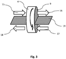
- the water remover 4 comprises a water uptaking material which is adapted to be regenerated by thermal energy. As shown in Figure 3 , this water up-taking material is loaded on a support structure 9, particularly a honeycomb structure, in the water remover 4. In the preferred embodiment of the water remover 4 shown in Figure 3 , the supporting structure 9 forms a rotating wheel rotating with respect to a separating plate 19 around its wheel axis.
- the water uptaking material in the water remover 4 is a water adsorbent material, preferably silicate, and more preferably zeolite, forming a so called rotor adsorption dehumidifier.
- the water uptaking material may be also an absorbing material.
- wet air 15 flows through the support structure 9 carrying the adsorbent or absorbent material and leaves the water remover 4 as dry air 16 which is then led to the metal air battery 2 (not shown).
- the warm gas 17 from the metal air battery 2, poor in oxygen flows through the rotating wheel of the water remover 4 on the other side of the separating plate 19 and carries away humidity stored in the adsorbent or absorbent material on the supporting structure 9.
- the wet, cooled down exhaust gas 18 leaves then the water remover 4 on the other side and is led via an exhaust pipe to the environment (not shown).
- the rotating wheel with the supporting structure 9 turns constantly as indicated by the arrow on the wheel in Figure 3 .
- the adsorbent material or absorbent material on the supporting structure 9 is constantly regenerated while constantly removing water.
- the water remover 4 has to be regenerated during a regeneration phase in which the process of water removal has to be stopped.
- there are preferably two water removers 4 in the system 1 such that one can be regenerated while the other one dehumidifies ambient air 3.
- the water remover is a condensation dryer utilizing thermal energy delivered by the warm exhaust gas 17 of the metal air battery 2 and/or the heat exchangers 7, 8 to run the condensation process.
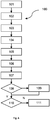
- Figure 4 shows a preferred embodiment of the inventive method 100 to operate a system 1 as specified with respect to Figures 1 to 3 . It is evident to the person skilled in the art that the steps shown in Figure 2 may be arranged in a different order.
- a metal air battery 2, particularly a lithium air battery is operated with ambient air 3, 101. Water is removed from the ambient air 3 with a water remover 4, 102.
- the metal air battery 2 preferably supplies a substantially constant first electrical power 103.
- a variable second electrical power is supplied by a high power battery 10, preferably a lithium ion battery 104.
- the supplied second electric power is preferably adapted to the demand of load 14, particularly an electrical propulsion 14 of a vehicle 13, 105.
- Thermal energy, particularly waste heat, from the metal air battery 2 is preferably redirected towards the water remover 4, 106. Preferably, the redirecting of the thermal energy is also controlled based on the electrical power demand 107.
- the high power battery 10 is charged with electrical energy from the high capacity battery 2, 109, if the power delivered by the high power battery is higher than the power demand of the load.
- the inventive method 100 comprises a further step of controlling if a medium for redirecting the thermal energy is hot enough for efficient regeneration of the water remover 4 110. If the medium is not hot enough, an additional heater heats the medium 111.
- the use of the additional heater 12 is especially important during the start-up phase of the system 1, where no thermal energy is supplied to the water remover 4. In this case, further electrical energy of the high power battery 10 and/or the public electricity grid is used to operate the additional heater 12.
Landscapes
- Engineering & Computer Science (AREA)
- Chemical Kinetics & Catalysis (AREA)
- Sustainable Development (AREA)
- Sustainable Energy (AREA)
- Chemical & Material Sciences (AREA)
- Life Sciences & Earth Sciences (AREA)
- Electrochemistry (AREA)
- General Chemical & Material Sciences (AREA)
- Manufacturing & Machinery (AREA)
- Power Engineering (AREA)
- Transportation (AREA)
- Mechanical Engineering (AREA)
- Electric Propulsion And Braking For Vehicles (AREA)
Claims (14)
- System (1) zum Bereitstellen von elektrischer Energie, insbesondere in einem Fahrzeug, aufweisend:eine Metall-Luft-Batterie (2), insbesondere eine Lithium-Luft-Batterie, die mit Umgebungsluft (3) betrieben wird,einen einzelnen Wasserentferner (4) zur konstanten Entfernung von Wasser aus der Umgebungsluft (3), der ein wasseraufnehmendes Material aufweist, undein erstes Modul (5), das geeignet ist, thermische Abwärmeenergie der Metall-Luft-Batterie (2) zum Wasserentferner (4) hin umzuleiten,wobei der Wasserentferner (4) geeignet ist, die thermische Abwärmeenergie für seinen Betrieb zu nutzen,wobei der Wasserentferner (4), insbesondere sein Wasseraufnahmematerial, geeignet ist, durch thermische Energie regeneriert zu werden, und wobei der Wasserentferner (4) eine Stützstruktur (9) aufweist, auf die das Wasseraufnahmematerial aufgebracht ist, undwobei die Stützstruktur (9) ein Rad ist, das sich relativ zu einer Trennplatte (19) dreht, wobei das Wasseraufnahmematerial auf einer Seite der Trennplatte (19) ständig regeneriert wird, während das Wasseraufnahmematerial auf der anderen Seite der Trennplatte (19) ständig Wasser entfernt.
- System (1) nach Anspruch 1, wobei das erste Modul (5) ein Leitungssystem (6) aufweist, insbesondere einen Heizkreislauf, zum Transport eines Mediums zur Übertragung der Wärmeenergie auf den Wasserentferner, wobei das erste Modul (5) dazu geeignet ist, die Regeneration des Wasserentferners (4) zu steuern.
- System (1) nach Anspruch 2, wobei das Medium eine Abluft der Metall-Luft-Batterie (2) und/oder Wasser ist.
- System (1) nach einem der vorhergehenden Ansprüche, wobei das erste Modul (5)
mindestens einen Wärmetauscher (7, 8) aufweist, der geeignet ist, Wärmeenergie durch ein Medium auf den Wasserentferner (4) zu übertragen. - System (1) nach einem der vorstehenden Ansprüche, wobei die Stützstruktur (9) eine Wabenstruktur aufweist, auf die das wasseraufnehmende Material aufgebracht ist.
- System (1) nach Anspruch 5, bei dem eine Abluft der Metall-Luft-Batterie (2) durch die Stützstruktur (9) strömt, um das wasseraufnehmende Material zu regenerieren.
- System (1) nach einem der Ansprüche 1 bis 4, wobei der Wasserentferner (4) durch Kondensationstrocknung funktioniert.
- System (1) nach einem der vorstehenden Ansprüche, das ferner einen internen Verbrennungsmotor (11) aufweist, insbesondere einen Range-Extender, wobei das erste Modul (5) ferner geeignet ist, thermische Energie, insbesondere Abwärme, vom internen Verbrennungsmotor (11) zum Wasserentferner (4) umzuleiten, insbesondere durch Integration eines Kühlkreislaufs des Verbrennungsmotors (11) in einen Heizkreislauf (6) des ersten Moduls (5).
- System (1) nach einem der vorstehenden Ansprüche, das ferner einen zusätzlichen Erhitzer (12) zur Versorgung des Wasserentferners (4) mit zusätzlicher Wärmeenergie aufweist.
- Fahrzeug (13) mit elektrischem Antrieb (14), wobei die für den elektrischen Antrieb (14) verwendete elektrische Energie in einem System (1) nach einem der Ansprüche 1 bis 9 gespeichert wird.
- Verfahren (100) zum Bereitstellen elektrischer Energie, insbesondere in einem Fahrzeug, aufweisend die folgenden Schritte:Betreiben (101) einer Metall-Luft-Batterie (2), insbesondere einer Lithium-Luft-Batterie, mit Umgebungsluft (3);ständiges Entfernen (102) von Wasser aus der Umgebungsluft (3) mit einem einzelnen Wasserentferner (4), der geeignet ist, Wärmeenergie für seinen Betrieb zu nutzen, undUmleitung (106) thermischer Abwärmeenergie mindestens der Metall-Luft-Batterie (2) zum Wasserentferner (4) hin.
- Verfahren (100) nach Anspruch 11, bei dem das Wasser durch Adsorptionsentfeuchtung und/oder Absorptionsentfeuchtung entfernt wird (101), und das ferner den folgenden Schritt aufweist:
Regenerieren (103) des Wasserentferners (4), insbesondere eines wasseradsorbierenden Materials und/oder eines wasserabsorbierenden Materials des Wasserentferners (4), durch Wärmeenergie. - Verfahren (100) nach Anspruch 12, das außerdem die folgenden Schritte aufweist:
Drehen einer Stützstruktur (9) in Form eines Rades relativ zu einer Trennplatte (19), wobei das wasseradsorbierende Material und/oder das wasserabsorbierende Material auf einer Seite der Trennplatte (19) ständig regeneriert wird, während das wasseradsorbierende Material und/oder das wasserabsorbierende Material auf der anderen Seite der Trennplatte (19) ständig Wasser entfernt. - Verfahren (100) nach Anspruch 12, wobei das Wasser durch Kondensationstrocknung unter Nutzung der Wärmeenergie der Metall-Luft-Batterie (2) entfernt wird.
Applications Claiming Priority (1)
| Application Number | Priority Date | Filing Date | Title |
|---|---|---|---|
| PCT/EP2014/073920 WO2016070925A1 (en) | 2014-11-06 | 2014-11-06 | System and method for supplying electrical energy from a metal air battery |
Publications (2)
| Publication Number | Publication Date |
|---|---|
| EP3216079A1 EP3216079A1 (de) | 2017-09-13 |
| EP3216079B1 true EP3216079B1 (de) | 2020-05-06 |
Family
ID=51866158
Family Applications (1)
| Application Number | Title | Priority Date | Filing Date |
|---|---|---|---|
| EP14793856.7A Active EP3216079B1 (de) | 2014-11-06 | 2014-11-06 | System und verfahren zur stromversorgung aus einer metall-luft-batterie |
Country Status (2)
| Country | Link |
|---|---|
| EP (1) | EP3216079B1 (de) |
| WO (1) | WO2016070925A1 (de) |
Families Citing this family (1)
| Publication number | Priority date | Publication date | Assignee | Title |
|---|---|---|---|---|
| CN116788083A (zh) * | 2023-06-09 | 2023-09-22 | 淮安电智造电子科技有限公司 | 一种具有防护功能的充电桩 |
Family Cites Families (5)
| Publication number | Priority date | Publication date | Assignee | Title |
|---|---|---|---|---|
| US5510209A (en) | 1995-01-05 | 1996-04-23 | Eic Laboratories, Inc. | Solid polymer electrolyte-based oxygen batteries |
| DE60217086T2 (de) | 2001-04-05 | 2007-04-12 | Electrovaya Inc., Mississauga | Energieträger für variierende lasten |
| JP2010009896A (ja) * | 2008-06-26 | 2010-01-14 | Toyota Motor Corp | 燃料電池システム |
| US8481187B2 (en) | 2009-09-10 | 2013-07-09 | Battelle Memorial Institute | High-energy metal air batteries |
| US8247097B1 (en) * | 2011-06-10 | 2012-08-21 | Tesla Motors, Inc. | Method of controlling battery pack humidity utilizing an active reactivation system |
-
2014
- 2014-11-06 WO PCT/EP2014/073920 patent/WO2016070925A1/en not_active Ceased
- 2014-11-06 EP EP14793856.7A patent/EP3216079B1/de active Active
Non-Patent Citations (1)
| Title |
|---|
| None * |
Also Published As
| Publication number | Publication date |
|---|---|
| EP3216079A1 (de) | 2017-09-13 |
| WO2016070925A1 (en) | 2016-05-12 |
Similar Documents
| Publication | Publication Date | Title |
|---|---|---|
| CN103879412B (zh) | 有轨电车动力系统及控制方法 | |
| US8449997B2 (en) | Thermal energy transfer system for a power source utilizing both metal-air and non-metal-air battery packs | |
| CN103963605B (zh) | 车辆热泵系统和利用蓄热的方法 | |
| JP5794091B2 (ja) | 電源システム | |
| JP2017115891A (ja) | 車両内燃機関の排気ガスからのco2の車載での回収及び貯蔵のための廃熱を利用する膜分離方法 | |
| US20100055508A1 (en) | Fuel cell systems with water recovery from fuel cell effluent | |
| JP5516524B2 (ja) | 電源システム | |
| Colmenar-Santos et al. | Residual heat use generated by a 12 kW fuel cell in an electric vehicle heating system | |
| CN106064560B (zh) | 燃料电池混合动力系统及其控制方法 | |
| JP6545247B1 (ja) | エネルギーマネージメントシステム | |
| WO2019098067A1 (ja) | 電動車両 | |
| EP3216079B1 (de) | System und verfahren zur stromversorgung aus einer metall-luft-batterie | |
| CN115692948A (zh) | 具有热能存储部件的电池组模块 | |
| EP3216080B1 (de) | System und verfahren zum betreiben einer metall-luft-batterie mit umgebungsluft | |
| JP2005312243A (ja) | 移動体の回生電力制御装置 | |
| CN106515481A (zh) | 一种具有轮毂发电机的燃料电池汽车及续航控制方法 | |
| JP4645006B2 (ja) | 車載燃料電池システム | |
| JP4974678B2 (ja) | 吸着アキュムレータを備えた移動用として使用可能な燃料電池システム | |
| JP2004206928A (ja) | 燃料電池システム | |
| CN116764380A (zh) | 具有集成的co2收集器的快速充电站 | |
| EP4438382A1 (de) | Brennstoffzelle als elektrolyseur in brennstoffzellen-elektrofahrzeugen zur bordeigenen wasserstofferzeugung | |
| WO2016155841A1 (en) | System and method for supplying electrical energy from a metal air battery operated with ambient air | |
| JP2023147628A (ja) | 二酸化炭素回収装置及び二酸化炭素の回収方法 | |
| US20170229727A1 (en) | An energy carrier system for a vehicle | |
| EP3216077B1 (de) | Verfahren und system zum betreiben einer metall-luft-batterie mit gesteuerter sauerstoffversorgung |
Legal Events
| Date | Code | Title | Description |
|---|---|---|---|
| STAA | Information on the status of an ep patent application or granted ep patent |
Free format text: STATUS: THE INTERNATIONAL PUBLICATION HAS BEEN MADE |
|
| PUAI | Public reference made under article 153(3) epc to a published international application that has entered the european phase |
Free format text: ORIGINAL CODE: 0009012 |
|
| STAA | Information on the status of an ep patent application or granted ep patent |
Free format text: STATUS: REQUEST FOR EXAMINATION WAS MADE |
|
| 17P | Request for examination filed |
Effective date: 20170524 |
|
| AK | Designated contracting states |
Kind code of ref document: A1 Designated state(s): AL AT BE BG CH CY CZ DE DK EE ES FI FR GB GR HR HU IE IS IT LI LT LU LV MC MK MT NL NO PL PT RO RS SE SI SK SM TR |
|
| AX | Request for extension of the european patent |
Extension state: BA ME |
|
| RAP1 | Party data changed (applicant data changed or rights of an application transferred) |
Owner name: BAYERISCHE MOTOREN WERKE AKTIENGESELLSCHAFT |
|
| DAX | Request for extension of the european patent (deleted) | ||
| STAA | Information on the status of an ep patent application or granted ep patent |
Free format text: STATUS: EXAMINATION IS IN PROGRESS |
|
| 17Q | First examination report despatched |
Effective date: 20190617 |
|
| GRAP | Despatch of communication of intention to grant a patent |
Free format text: ORIGINAL CODE: EPIDOSNIGR1 |
|
| STAA | Information on the status of an ep patent application or granted ep patent |
Free format text: STATUS: GRANT OF PATENT IS INTENDED |
|
| RIC1 | Information provided on ipc code assigned before grant |
Ipc: H01M 16/00 20060101ALI20191031BHEP Ipc: H01M 12/08 20060101AFI20191031BHEP Ipc: B60L 50/72 20190101ALI20191031BHEP Ipc: H01M 8/04119 20160101ALI20191031BHEP Ipc: H01M 8/04007 20160101ALI20191031BHEP |
|
| INTG | Intention to grant announced |
Effective date: 20191121 |
|
| GRAS | Grant fee paid |
Free format text: ORIGINAL CODE: EPIDOSNIGR3 |
|
| GRAA | (expected) grant |
Free format text: ORIGINAL CODE: 0009210 |
|
| STAA | Information on the status of an ep patent application or granted ep patent |
Free format text: STATUS: THE PATENT HAS BEEN GRANTED |
|
| AK | Designated contracting states |
Kind code of ref document: B1 Designated state(s): AL AT BE BG CH CY CZ DE DK EE ES FI FR GB GR HR HU IE IS IT LI LT LU LV MC MK MT NL NO PL PT RO RS SE SI SK SM TR |
|
| REG | Reference to a national code |
Ref country code: GB Ref legal event code: FG4D |
|
| RIN1 | Information on inventor provided before grant (corrected) |
Inventor name: INOUE, TOSHIHIKO Inventor name: NISHIKOORI, HIDETAKA Inventor name: PASCHOS, ODYSSEAS Inventor name: HANDA, TOKUHIKO Inventor name: TSIOUVARAS, NIKOLAOS Inventor name: LAMP, PETER Inventor name: NUERNBERGER, SIMON Inventor name: OBERHUMER, PHILIPP |
|
| REG | Reference to a national code |
Ref country code: CH Ref legal event code: EP Ref country code: AT Ref legal event code: REF Ref document number: 1268310 Country of ref document: AT Kind code of ref document: T Effective date: 20200515 |
|
| REG | Reference to a national code |
Ref country code: IE Ref legal event code: FG4D |
|
| REG | Reference to a national code |
Ref country code: DE Ref legal event code: R096 Ref document number: 602014065113 Country of ref document: DE |
|
| REG | Reference to a national code |
Ref country code: LT Ref legal event code: MG4D |
|
| REG | Reference to a national code |
Ref country code: NL Ref legal event code: MP Effective date: 20200506 |
|
| PG25 | Lapsed in a contracting state [announced via postgrant information from national office to epo] |
Ref country code: SE Free format text: LAPSE BECAUSE OF FAILURE TO SUBMIT A TRANSLATION OF THE DESCRIPTION OR TO PAY THE FEE WITHIN THE PRESCRIBED TIME-LIMIT Effective date: 20200506 Ref country code: IS Free format text: LAPSE BECAUSE OF FAILURE TO SUBMIT A TRANSLATION OF THE DESCRIPTION OR TO PAY THE FEE WITHIN THE PRESCRIBED TIME-LIMIT Effective date: 20200906 Ref country code: FI Free format text: LAPSE BECAUSE OF FAILURE TO SUBMIT A TRANSLATION OF THE DESCRIPTION OR TO PAY THE FEE WITHIN THE PRESCRIBED TIME-LIMIT Effective date: 20200506 Ref country code: NO Free format text: LAPSE BECAUSE OF FAILURE TO SUBMIT A TRANSLATION OF THE DESCRIPTION OR TO PAY THE FEE WITHIN THE PRESCRIBED TIME-LIMIT Effective date: 20200806 Ref country code: GR Free format text: LAPSE BECAUSE OF FAILURE TO SUBMIT A TRANSLATION OF THE DESCRIPTION OR TO PAY THE FEE WITHIN THE PRESCRIBED TIME-LIMIT Effective date: 20200807 Ref country code: PT Free format text: LAPSE BECAUSE OF FAILURE TO SUBMIT A TRANSLATION OF THE DESCRIPTION OR TO PAY THE FEE WITHIN THE PRESCRIBED TIME-LIMIT Effective date: 20200907 Ref country code: LT Free format text: LAPSE BECAUSE OF FAILURE TO SUBMIT A TRANSLATION OF THE DESCRIPTION OR TO PAY THE FEE WITHIN THE PRESCRIBED TIME-LIMIT Effective date: 20200506 |
|
| PG25 | Lapsed in a contracting state [announced via postgrant information from national office to epo] |
Ref country code: HR Free format text: LAPSE BECAUSE OF FAILURE TO SUBMIT A TRANSLATION OF THE DESCRIPTION OR TO PAY THE FEE WITHIN THE PRESCRIBED TIME-LIMIT Effective date: 20200506 Ref country code: LV Free format text: LAPSE BECAUSE OF FAILURE TO SUBMIT A TRANSLATION OF THE DESCRIPTION OR TO PAY THE FEE WITHIN THE PRESCRIBED TIME-LIMIT Effective date: 20200506 Ref country code: BG Free format text: LAPSE BECAUSE OF FAILURE TO SUBMIT A TRANSLATION OF THE DESCRIPTION OR TO PAY THE FEE WITHIN THE PRESCRIBED TIME-LIMIT Effective date: 20200806 Ref country code: RS Free format text: LAPSE BECAUSE OF FAILURE TO SUBMIT A TRANSLATION OF THE DESCRIPTION OR TO PAY THE FEE WITHIN THE PRESCRIBED TIME-LIMIT Effective date: 20200506 |
|
| REG | Reference to a national code |
Ref country code: AT Ref legal event code: MK05 Ref document number: 1268310 Country of ref document: AT Kind code of ref document: T Effective date: 20200506 |
|
| PG25 | Lapsed in a contracting state [announced via postgrant information from national office to epo] |
Ref country code: NL Free format text: LAPSE BECAUSE OF FAILURE TO SUBMIT A TRANSLATION OF THE DESCRIPTION OR TO PAY THE FEE WITHIN THE PRESCRIBED TIME-LIMIT Effective date: 20200506 Ref country code: AL Free format text: LAPSE BECAUSE OF FAILURE TO SUBMIT A TRANSLATION OF THE DESCRIPTION OR TO PAY THE FEE WITHIN THE PRESCRIBED TIME-LIMIT Effective date: 20200506 |
|
| PG25 | Lapsed in a contracting state [announced via postgrant information from national office to epo] |
Ref country code: SM Free format text: LAPSE BECAUSE OF FAILURE TO SUBMIT A TRANSLATION OF THE DESCRIPTION OR TO PAY THE FEE WITHIN THE PRESCRIBED TIME-LIMIT Effective date: 20200506 Ref country code: ES Free format text: LAPSE BECAUSE OF FAILURE TO SUBMIT A TRANSLATION OF THE DESCRIPTION OR TO PAY THE FEE WITHIN THE PRESCRIBED TIME-LIMIT Effective date: 20200506 Ref country code: DK Free format text: LAPSE BECAUSE OF FAILURE TO SUBMIT A TRANSLATION OF THE DESCRIPTION OR TO PAY THE FEE WITHIN THE PRESCRIBED TIME-LIMIT Effective date: 20200506 Ref country code: CZ Free format text: LAPSE BECAUSE OF FAILURE TO SUBMIT A TRANSLATION OF THE DESCRIPTION OR TO PAY THE FEE WITHIN THE PRESCRIBED TIME-LIMIT Effective date: 20200506 Ref country code: EE Free format text: LAPSE BECAUSE OF FAILURE TO SUBMIT A TRANSLATION OF THE DESCRIPTION OR TO PAY THE FEE WITHIN THE PRESCRIBED TIME-LIMIT Effective date: 20200506 Ref country code: AT Free format text: LAPSE BECAUSE OF FAILURE TO SUBMIT A TRANSLATION OF THE DESCRIPTION OR TO PAY THE FEE WITHIN THE PRESCRIBED TIME-LIMIT Effective date: 20200506 Ref country code: RO Free format text: LAPSE BECAUSE OF FAILURE TO SUBMIT A TRANSLATION OF THE DESCRIPTION OR TO PAY THE FEE WITHIN THE PRESCRIBED TIME-LIMIT Effective date: 20200506 |
|
| REG | Reference to a national code |
Ref country code: DE Ref legal event code: R097 Ref document number: 602014065113 Country of ref document: DE |
|
| PG25 | Lapsed in a contracting state [announced via postgrant information from national office to epo] |
Ref country code: PL Free format text: LAPSE BECAUSE OF FAILURE TO SUBMIT A TRANSLATION OF THE DESCRIPTION OR TO PAY THE FEE WITHIN THE PRESCRIBED TIME-LIMIT Effective date: 20200506 Ref country code: SK Free format text: LAPSE BECAUSE OF FAILURE TO SUBMIT A TRANSLATION OF THE DESCRIPTION OR TO PAY THE FEE WITHIN THE PRESCRIBED TIME-LIMIT Effective date: 20200506 |
|
| PLBE | No opposition filed within time limit |
Free format text: ORIGINAL CODE: 0009261 |
|
| STAA | Information on the status of an ep patent application or granted ep patent |
Free format text: STATUS: NO OPPOSITION FILED WITHIN TIME LIMIT |
|
| 26N | No opposition filed |
Effective date: 20210209 |
|
| PG25 | Lapsed in a contracting state [announced via postgrant information from national office to epo] |
Ref country code: SI Free format text: LAPSE BECAUSE OF FAILURE TO SUBMIT A TRANSLATION OF THE DESCRIPTION OR TO PAY THE FEE WITHIN THE PRESCRIBED TIME-LIMIT Effective date: 20200506 |
|
| PG25 | Lapsed in a contracting state [announced via postgrant information from national office to epo] |
Ref country code: MC Free format text: LAPSE BECAUSE OF FAILURE TO SUBMIT A TRANSLATION OF THE DESCRIPTION OR TO PAY THE FEE WITHIN THE PRESCRIBED TIME-LIMIT Effective date: 20200506 |
|
| REG | Reference to a national code |
Ref country code: CH Ref legal event code: PL |
|
| PG25 | Lapsed in a contracting state [announced via postgrant information from national office to epo] |
Ref country code: LU Free format text: LAPSE BECAUSE OF NON-PAYMENT OF DUE FEES Effective date: 20201106 |
|
| REG | Reference to a national code |
Ref country code: BE Ref legal event code: MM Effective date: 20201130 |
|
| PG25 | Lapsed in a contracting state [announced via postgrant information from national office to epo] |
Ref country code: LI Free format text: LAPSE BECAUSE OF NON-PAYMENT OF DUE FEES Effective date: 20201130 Ref country code: CH Free format text: LAPSE BECAUSE OF NON-PAYMENT OF DUE FEES Effective date: 20201130 |
|
| PG25 | Lapsed in a contracting state [announced via postgrant information from national office to epo] |
Ref country code: IE Free format text: LAPSE BECAUSE OF NON-PAYMENT OF DUE FEES Effective date: 20201106 |
|
| PG25 | Lapsed in a contracting state [announced via postgrant information from national office to epo] |
Ref country code: TR Free format text: LAPSE BECAUSE OF FAILURE TO SUBMIT A TRANSLATION OF THE DESCRIPTION OR TO PAY THE FEE WITHIN THE PRESCRIBED TIME-LIMIT Effective date: 20200506 Ref country code: MT Free format text: LAPSE BECAUSE OF FAILURE TO SUBMIT A TRANSLATION OF THE DESCRIPTION OR TO PAY THE FEE WITHIN THE PRESCRIBED TIME-LIMIT Effective date: 20200506 Ref country code: CY Free format text: LAPSE BECAUSE OF FAILURE TO SUBMIT A TRANSLATION OF THE DESCRIPTION OR TO PAY THE FEE WITHIN THE PRESCRIBED TIME-LIMIT Effective date: 20200506 |
|
| PG25 | Lapsed in a contracting state [announced via postgrant information from national office to epo] |
Ref country code: MK Free format text: LAPSE BECAUSE OF FAILURE TO SUBMIT A TRANSLATION OF THE DESCRIPTION OR TO PAY THE FEE WITHIN THE PRESCRIBED TIME-LIMIT Effective date: 20200506 |
|
| PG25 | Lapsed in a contracting state [announced via postgrant information from national office to epo] |
Ref country code: BE Free format text: LAPSE BECAUSE OF NON-PAYMENT OF DUE FEES Effective date: 20201130 |
|
| P01 | Opt-out of the competence of the unified patent court (upc) registered |
Effective date: 20230427 |
|
| REG | Reference to a national code |
Ref country code: DE Ref legal event code: R082 Ref document number: 602014065113 Country of ref document: DE Representative=s name: PLATZOEDER PATENTANWALTSGESELLSCHAFT MBH, DE |
|
| PGFP | Annual fee paid to national office [announced via postgrant information from national office to epo] |
Ref country code: DE Payment date: 20251110 Year of fee payment: 12 |
|
| PGFP | Annual fee paid to national office [announced via postgrant information from national office to epo] |
Ref country code: GB Payment date: 20251120 Year of fee payment: 12 |
|
| PGFP | Annual fee paid to national office [announced via postgrant information from national office to epo] |
Ref country code: IT Payment date: 20251128 Year of fee payment: 12 |
|
| PGFP | Annual fee paid to national office [announced via postgrant information from national office to epo] |
Ref country code: FR Payment date: 20251120 Year of fee payment: 12 |