EP3216231B1 - Guide d'ondes de boîtier pour capteur acoustique à compensation du temps de propagation électronique - Google Patents
Guide d'ondes de boîtier pour capteur acoustique à compensation du temps de propagation électronique Download PDFInfo
- Publication number
- EP3216231B1 EP3216231B1 EP15856698.4A EP15856698A EP3216231B1 EP 3216231 B1 EP3216231 B1 EP 3216231B1 EP 15856698 A EP15856698 A EP 15856698A EP 3216231 B1 EP3216231 B1 EP 3216231B1
- Authority
- EP
- European Patent Office
- Prior art keywords
- acoustic
- transducers
- signals
- signal
- ports
- Prior art date
- Legal status (The legal status is an assumption and is not a legal conclusion. Google has not performed a legal analysis and makes no representation as to the accuracy of the status listed.)
- Not-in-force
Links
Images


Classifications
-
- H—ELECTRICITY
- H04—ELECTRIC COMMUNICATION TECHNIQUE
- H04R—LOUDSPEAKERS, MICROPHONES, GRAMOPHONE PICK-UPS OR LIKE ACOUSTIC ELECTROMECHANICAL TRANSDUCERS; ELECTRIC HEARING AIDS; PUBLIC ADDRESS SYSTEMS
- H04R17/00—Piezoelectric transducers; Electrostrictive transducers
-
- G—PHYSICS
- G10—MUSICAL INSTRUMENTS; ACOUSTICS
- G10K—SOUND-PRODUCING DEVICES; METHODS OR DEVICES FOR PROTECTING AGAINST, OR FOR DAMPING, NOISE OR OTHER ACOUSTIC WAVES IN GENERAL; ACOUSTICS NOT OTHERWISE PROVIDED FOR
- G10K11/00—Methods or devices for transmitting, conducting or directing sound in general; Methods or devices for protecting against, or for damping, noise or other acoustic waves in general
- G10K11/002—Devices for damping, suppressing, obstructing or conducting sound in acoustic devices
-
- G—PHYSICS
- G01—MEASURING; TESTING
- G01S—RADIO DIRECTION-FINDING; RADIO NAVIGATION; DETERMINING DISTANCE OR VELOCITY BY USE OF RADIO WAVES; LOCATING OR PRESENCE-DETECTING BY USE OF THE REFLECTION OR RERADIATION OF RADIO WAVES; ANALOGOUS ARRANGEMENTS USING OTHER WAVES
- G01S15/00—Systems using the reflection or reradiation of acoustic waves, e.g. sonar systems
- G01S15/02—Systems using the reflection or reradiation of acoustic waves, e.g. sonar systems using reflection of acoustic waves
- G01S15/06—Systems determining the position data of a target
- G01S15/08—Systems for measuring distance only
- G01S15/10—Systems for measuring distance only using transmission of interrupted, pulse-modulated waves
-
- G—PHYSICS
- G01—MEASURING; TESTING
- G01S—RADIO DIRECTION-FINDING; RADIO NAVIGATION; DETERMINING DISTANCE OR VELOCITY BY USE OF RADIO WAVES; LOCATING OR PRESENCE-DETECTING BY USE OF THE REFLECTION OR RERADIATION OF RADIO WAVES; ANALOGOUS ARRANGEMENTS USING OTHER WAVES
- G01S7/00—Details of systems according to groups G01S13/00, G01S15/00, G01S17/00
- G01S7/52—Details of systems according to groups G01S13/00, G01S15/00, G01S17/00 of systems according to group G01S15/00
- G01S7/521—Constructional features
-
- G—PHYSICS
- G10—MUSICAL INSTRUMENTS; ACOUSTICS
- G10K—SOUND-PRODUCING DEVICES; METHODS OR DEVICES FOR PROTECTING AGAINST, OR FOR DAMPING, NOISE OR OTHER ACOUSTIC WAVES IN GENERAL; ACOUSTICS NOT OTHERWISE PROVIDED FOR
- G10K11/00—Methods or devices for transmitting, conducting or directing sound in general; Methods or devices for protecting against, or for damping, noise or other acoustic waves in general
- G10K11/18—Methods or devices for transmitting, conducting or directing sound
- G10K11/26—Sound-focusing or directing, e.g. scanning
- G10K11/34—Sound-focusing or directing, e.g. scanning using electrical steering of transducer arrays, e.g. beam steering
- G10K11/341—Circuits therefor
- G10K11/346—Circuits therefor using phase variation
-
- H—ELECTRICITY
- H04—ELECTRIC COMMUNICATION TECHNIQUE
- H04R—LOUDSPEAKERS, MICROPHONES, GRAMOPHONE PICK-UPS OR LIKE ACOUSTIC ELECTROMECHANICAL TRANSDUCERS; ELECTRIC HEARING AIDS; PUBLIC ADDRESS SYSTEMS
- H04R29/00—Monitoring arrangements; Testing arrangements
- H04R29/001—Monitoring arrangements; Testing arrangements for loudspeakers
- H04R29/002—Loudspeaker arrays
-
- H—ELECTRICITY
- H04—ELECTRIC COMMUNICATION TECHNIQUE
- H04R—LOUDSPEAKERS, MICROPHONES, GRAMOPHONE PICK-UPS OR LIKE ACOUSTIC ELECTROMECHANICAL TRANSDUCERS; ELECTRIC HEARING AIDS; PUBLIC ADDRESS SYSTEMS
- H04R2201/00—Details of transducers, loudspeakers or microphones covered by H04R1/00 but not provided for in any of its subgroups
- H04R2201/003—Mems transducers or their use
-
- H—ELECTRICITY
- H04—ELECTRIC COMMUNICATION TECHNIQUE
- H04R—LOUDSPEAKERS, MICROPHONES, GRAMOPHONE PICK-UPS OR LIKE ACOUSTIC ELECTROMECHANICAL TRANSDUCERS; ELECTRIC HEARING AIDS; PUBLIC ADDRESS SYSTEMS
- H04R2217/00—Details of magnetostrictive, piezoelectric, or electrostrictive transducers covered by H04R15/00 or H04R17/00 but not provided for in any of their subgroups
- H04R2217/03—Parametric transducers where sound is generated or captured by the acoustic demodulation of amplitude modulated ultrasonic waves
-
- H—ELECTRICITY
- H04—ELECTRIC COMMUNICATION TECHNIQUE
- H04R—LOUDSPEAKERS, MICROPHONES, GRAMOPHONE PICK-UPS OR LIKE ACOUSTIC ELECTROMECHANICAL TRANSDUCERS; ELECTRIC HEARING AIDS; PUBLIC ADDRESS SYSTEMS
- H04R29/00—Monitoring arrangements; Testing arrangements
- H04R29/004—Monitoring arrangements; Testing arrangements for microphones
- H04R29/005—Microphone arrays
-
- H—ELECTRICITY
- H04—ELECTRIC COMMUNICATION TECHNIQUE
- H04R—LOUDSPEAKERS, MICROPHONES, GRAMOPHONE PICK-UPS OR LIKE ACOUSTIC ELECTROMECHANICAL TRANSDUCERS; ELECTRIC HEARING AIDS; PUBLIC ADDRESS SYSTEMS
- H04R3/00—Circuits for transducers
- H04R3/04—Circuits for transducers for correcting frequency response
Definitions
- Time-of-flight (TOF) sonic rangefinders emit a signal composed of sound waves and measure the signal that is reflected off objects in the environment in order to measure the presence, range and/or direction to said objects.
- the range is determined by measuring the time of flight of the sound wave.
- Short duration pulses or temporally coded pulses allow the system to resolve multiple targets that are spaced in range.
- Phased array rangefinders incorporate multiple transmitters and/or receivers which are spatially separated in order to discern the direction (azimuth and/or elevation) to the objects.
- Typical acoustic transducer designs are membrane structures which are driven into flexural vibration using piezoelectric or capacitive actuation. The vibration of the membrane creates air motion which propagates as sound away from the transducer. Returning sound waves cause the transducer to vibrate and this motion is sensed by an electronic amplifier through piezoelectric or capacitive sensing techniques. Multiple transducers are fabricated on a single substrate using wafer fabrication techniques.
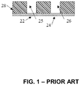
- An acoustic transducer array substrate 28 contains acoustic transducers 22 and 24 which are coupled through acoustic ports 25 and 26.
- Transducer designs may be released using a through-wafer etch which forms a trench beneath the transducer.
- the trench may be designed to be an acoustic resonator which has a length of approximately one quarter of a wavelength, as described in S. Shelton, O. Rozen, A. Guedes, R. Przybyla, B. Boser, and D. A.
- the phased array acoustic transducers 22, 24 are spatially separated in order to minimize the beamwidth of the acoustic signal when the array is used as a phased array transmitter and/or receiver.
- the spacing is a tradeoff between beamwidth and sidelobe level. When the spacing is increased, the beamwidth is reduced, but the sidelobe level increases.
- the array elements are preferentially spaced between one half wavelength and one wavelength apart. It is often desirable that each element in the array have a substantially isotropic acoustic radiation pattern such that the array can be electronically steered over a wide range of angles.
- the transducers 22, 24 In order to create an isotropic vibrating membrane transducer, the transducers 22, 24 must be designed to be smaller than the wavelength ⁇ of the sound wave. When the diameter of each transducer is smaller than the required spacing, there can be considerable unused area between each transducer, which increases the cost and size of the transducer array chip. A new method is required to reduce the considerable inactive space on a transducer substrate.
- US Patent Number 8,199,953 describes a method to connect multiple acoustic waveguides together above a single acoustic transducer, thereby producing an acoustic horn with multiple apertures.
- the intent of this multi-aperture horn is to take a single omnidirectional transducer and shape the acoustic output so that the single transducer produces a directional acoustic output.
- US 8,199,953 does not teach how to use acoustic waveguides in a phased array, nor does it teach how to use an array of waveguides together with an array of transducers.
- EP 0309003 A2 discloses a surface acoustic wave (SAW) device configured to operate as a spectrum analyzer, and having an array of input transducers disposed on a substrate in such positions as to produce a focused beam of acoustic energy at a focal arc, each position on the arc being representative of an input signal frequency.
- Output transducers produce electrical signals corresponding to the energy received at successive segments of the focal arc.
- a new method to design and operate phased array rangefinders is required to address the shortcomings in the state of the art.
- This disclosure describes a system and a method to use an array of ultrasonic transducers to emit and receive sound in a phased array fashion by using acoustic waveguides and electronic delays to achieve a desired acoustic radiation and reception pattern.
- the size of the transducer array can be greatly reduced while maintaining a desired acoustic beam pattern, significantly reducing manufacturing costs.
- a system to package an array of acoustic transducers is disclosed.
- the present disclosure describes how to package an array of transducers to increase the effective spacing between the transducers in order to improve the imaging properties of the array.
- a transducer array substrate 28 contains acoustic transducers 22 and 24 which are coupled through transducer acoustic ports 25, 26.
- the substrate 28 may be made of silicon, glass, plastic, or many other materials.
- the acoustic transducers 22, 24 may be made using a piezoelectric unimorph or multimorph structure with various piezoelectric materials including AIN, PZT (lead zirconate titanate), ZnO, KNN (K x Na 1-x NbO 3 ) or PMN-PT (lead magnesium niobate - lead titanate). They may also be actuated capacitively.
- the acoustic ports 25 and 26 may be formed, e.g., using a deep reactive ion etch or by other means.
- the transducer array substrate 28 is mounted to a chip package 40 which contains acoustic waveguides 34, 50 leading to acoustic ports 32, 30.
- Acoustic waveguides 34, 50 and transducer acoustic ports 25, 26 may be filled with a gas when the acoustic transducer is used to measure or emit sound signals in that gas.
- Acoustic waveguides 34, 50 and transducer acoustic ports 25, 26 may be filled with epoxy, liquid, gel, silicone, or other material with desirable acoustic impedance when the acoustic transducer is used to measure and/or emit sound signals in a fluid such as water or tissue such as a human body.
- chip package 40 many different materials may be used to make chip package 40; example materials include plastic, glass-reinforced epoxy laminate, ceramic, glass and/or metal or a combination of these materials. While the figures show only two acoustic ports 30,32 and two transducers 22, 24, this is for purposes of illustration only and it should be understood that many embodiments will have a multiplicity of ports and transducers.
- Chip package 40 may contain electrical signal routing and bond pads in order to make electrical connection to transducer array 28.
- the chip package 40 contains an electronic integrated circuit 44 which interfaces to transducer array 28 through electronic signal routing on the chip package 40.
- integrated circuit 44 may interface to transducer array 28 directly through wire bonds, bump bonds, ball-grid arrays, and/or through-silicon vias.
- Chip package 40 may contain a port 46 which permits equalization of the pressure on each side of acoustic transducers 22, 24.
- Chip package 40 may also be understood to be assembled in several pieces. These pieces may include a base layer 42, an intermediate layer 43, and an array-mounting layer 36 and a surface layer 38.
- the transducer array substrate 28 is attached to the array-mounting layer 36, which is attached to the intermediate layer 43.
- the intermediate layer 43 includes an opening large enough to receive the transducer array substrate 28.
- the intermediate layer 43 is attached to the base layer 42.
- chip package component layers 36, 38, 42, and43, and acoustic waveguides 34, 50 may be designed to be part of an external enclosure of a system which contains the acoustic transducer array.
- the external enclosure surface may be made of many different materials including glass, metal, plastic, or laminate material.
- surface layer 38 may be coated with an anti-scratch coating for durability.
- the acoustic ports 30, 32 in chip package 40 are spaced with a pitch that is less than 5 ⁇ and more specifically with a pitch between 1 ⁇ 2 ⁇ and ⁇ where ⁇ is the acoustic wavelength. Because the arrangements of ports 30, 32 determine the acoustic beam profile, the spacing of transducers 22 and 24 on array substrate 28 can be defined according to manufacturing requirements and may be either smaller or larger than the spacing of ports 30, 32 in chip package 40. Acoustic ports 30, 32 may also be designed to be larger or smaller than transducer acoustic ports 25, 26 in order to control the radiation pattern of the individual transducers.
- the lengths of the acoustic waveguides 34, 50 can be adjusted by an amount C to account for the end effects produced by ports 30, 32. It should be understood that the spacing of the acoustic ports 30, 32 may be non-uniform in order to realize a desired acoustic transmission or reception beam profile.
- the acoustic waveguides 34, 50 may be designed to couple uniformly spaced transducers 22, 24 to non-uniformly spaced acoustic ports 30, 32.
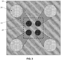
- Fig. 3 shows a top view of a chip package 40.
- Chip package surface layer 38 contains several acoustic ports 30 which are connected to transducer acoustic ports 26 through acoustic waveguides 34 which are between the array-mounting layer 36 and the chip package surface layer 38.
- the separation (i.e., spacing) and diameter of acoustic ports 30 is much larger than the separation and diameter of transducer acoustic ports 26.
- Fig. 4 shows a block diagram of an electrical subsystem which may be incorporated in whole or in part in integrated circuit 44 of Fig. 2 .
- the electrical subsystem sends and receives signals from an acoustic transducer array 28.
- package acoustic waveguide 58 is shorter than acoustic waveguide 32 or acoustic waveguide 34.
- This system is provided as way of example, and the methods described herein may be extended to cover arrays with different geometries or designs.
- acoustic waveguides 34, 50 may be designed to resonate with a length of 5 ⁇ /4 while acoustic waveguide 58 may be designed to resonate with a length of 3 ⁇ /4.
- the acoustic delay of acoustic waveguide 58 is 3/(4f o ) and the delays of waveguides 34, 50 are 5/(4f o ), where f o is the operational frequency.
- the transducer array 28 is transmitting a beam of sound with a steering angle normal to the array.
- the sound signals generated by the transducers 22, 24 and transmitted through acoustic waveguides 32, 58, and 34 must be emitted in phase such that the emitted waves interfere constructively on-axis in the far-field of the array.
- the electrical signals that excite transducer 24 must be delayed by 1/(2f o ). This is accomplished by delaying the signal from signal generation block 70 in a time/phase delay block 72, 76.
- the time/phase delay block 72, 76 may be implemented by shifting the phase of the signal, especially in the case where the phase coherence length of the signal is many periods long compared to the desired phase delay.
- the time/phase delay block 72, 76 could instead be implemented with a time delay block, especially in the case where the phase coherence length of the signal is short compared to the desired delay. It is appreciated that in some embodiments, focusing of the beam may be desired. In these cases, the emitted waveforms may be designed to be in phase at the focal depth of the waveform. In any case, the time/phase delay block 72, 76 implements an additional time/phase delay in order to achieve the desired focusing condition.
- each signal passes through separate amplifiers 74 and separate transmit switches 78.
- receive switches 80 are open to prevent the transmit signals from damaging the receive circuits.
- Many other embodiments are possible, including one where the transmit amplifiers 74 and receive amplifiers 82 are connected to separate electrodes on each transducer, and an alternate switching configuration is used.
- the desired time delays between the signals emitted at waveguide ports 58 and 34 relative to the signal emitted at waveguide port 32 are 1/(4f o ) and 1/(2f o ), respectively.
- the final delays implemented by the time/phase delay blocks should be 3/(4f o ) and 1/(2f o ), respectively.
- this embodiment constitutes one way to implement the required delays or phase shifts.
- Other embodiments such as those that omit time/phase delay blocks 72, 76 and use signal generation block 70 to generate the correct signals could achieve the same functionality and are intended to be within the scope of this disclosure.
- receive switches 80 pass the signal to receive processing block 82 and then to time/phase delay blocks 84, 86.
- Receive processing blocks 82 may include amplifiers, filters, and/or analog-to-digital converters, so the processing of the received signals may be implemented in the analog or digital domain.
- Time/phase delay block 86 shifts or delays the signal from transducer 24 by 1/(2f o ) before the signals pass into beamforming and target recognition block 88.
- Beamforming and target recognition block 88 may be a hardware or software block. If it is a hardware block, it may work in the analog or digital domain. This block may extract features from the received signals or perform spatial filtering of the received signal. Details of an example of a beamforming and target recognition block are described, e.g., in R. Przybyla, H.-Y. Tang, S. Shelton, A. Guedes, D. Horsley, and B. Boser, "Ultrasonic 3D Rangefinder on a Chip," Journal of Solid State Circuits, vol. 50, no. 1, pp.320-334, January 2015 .
- the transducer array 28 may be controlled such that a subset or the full set of transducers is used to transmit sound which is emitted from the corresponding acoustic ports having a first acoustic beam profile.
- the transmitted beam profile may have undesirable properties such as grating lobes.
- the transducers may be controlled such that a different subset or full set of transducers is used to receive sound signals which are processed in beamforming and target recognition block 88.
Landscapes
- Engineering & Computer Science (AREA)
- Physics & Mathematics (AREA)
- Acoustics & Sound (AREA)
- Signal Processing (AREA)
- Remote Sensing (AREA)
- Radar, Positioning & Navigation (AREA)
- General Physics & Mathematics (AREA)
- Computer Networks & Wireless Communication (AREA)
- Multimedia (AREA)
- Health & Medical Sciences (AREA)
- Otolaryngology (AREA)
- General Health & Medical Sciences (AREA)
- Ultra Sonic Daignosis Equipment (AREA)
- Measurement Of Velocity Or Position Using Acoustic Or Ultrasonic Waves (AREA)
- Transducers For Ultrasonic Waves (AREA)
- Investigating Or Analyzing Materials By The Use Of Ultrasonic Waves (AREA)
Claims (12)
- Boîtier de transducteur acoustique d'émission et de réception de signaux ultrasonores, comprenant :un réseau de transducteurs acoustiques (28) ayant une pluralité de transducteurs acoustiques (22, 23, 24) formés sur un substrat ;un boîtier de puce (40) fixé au réseau de transducteurs acoustiques, dans lequel le boîtier de puce comprend une pluralité de guides d'ondes acoustiques (34, 50, 58) couplés à une pluralité de ports acoustiques (30, 32), dans lequel chaque guide d'ondes acoustiques dans la pluralité de guides d'ondes acoustiques est couplé entre un transducteur acoustique correspondant dans la pluralité de transducteurs acoustiques et un port acoustique correspondant dans la pluralité de ports acoustiques, dans lequel un espacement d'une paire de ports acoustiques dans la pluralité de ports acoustiques est différent d'un espacement d'une paire de transducteurs acoustiques correspondante dans la pluralité de transducteurs acoustiques ; caractérisé en ce que le boîtier de transducteur acoustique comprend en outreun circuit intégré connecté au réseau de transducteurs acoustiques, dans lequel le circuit intégré comprend une unité de génération de signal (70) configurée pour générer une pluralité de signaux de commande, dans lequel chaque signal de commande de la pluralité de signaux de commande commande un transducteur correspondant de la pluralité de transducteurs, l'unité de génération de signal comprenant en outre une pluralité d'éléments de temps de propagation couplés entre l'unité de génération de signal et le réseau de transducteurs acoustiques, dans lequel chaque élément de temps de propagation de la pluralité d'éléments de temps de propagation applique un temps de propagation à un signal de commande correspondant de la pluralité de signaux de commande, dans lequel le temps de propagation compense un décalage de temps de propagation de guide d'ondes.
- Boîtier de transducteur acoustique selon la revendication 1, dans lequel l'espacement de la paire de ports acoustiques dans la pluralité de ports acoustiques est plus grand que l'espacement de la paire de transducteurs acoustiques correspondante dans la pluralité de transducteurs acoustiques.
- Boîtier de transducteur acoustique selon la revendication 1, dans lequel l'espacement entre les ports acoustiques dans la pluralité de ports acoustiques n'est pas uniforme, et éventuellement dans lequel le pas est compris entre ½ λ et λ.
- Boîtier de transducteur acoustique selon la revendication 1, dans lequel un ou plusieurs guides d'ondes acoustiques dans la pluralité de guides d'ondes acoustiques sont caractérisés par une longueur de ¼ λ∗ (2n-1) +C, où λ est une longueur d'onde acoustique, n = est un positif entier et C est un terme de correction qui prend en compte les effets finaux produits par les ports acoustiques.
- Boîtier de transducteur acoustique selon la revendication 1, dans lequel le circuit intégré est fixé au boîtier de puce.
- Boîtier de transducteur acoustique selon la revendication 1, comprenant en outre une pluralité d'amplificateurs de signal couplés entre l'unité de génération de signal et le réseau de transducteurs acoustiques, dans lequel chaque amplificateur de signal de la pluralité d'amplificateurs de signal amplifie un signal de commande correspondant de la pluralité de signaux de commande.
- Boîtier de transducteur acoustique selon la revendication 1, dans lequel le circuit intégré comprend un bloc de formation de faisceaux et de reconnaissance de cible couplé au réseau de transducteurs acoustiques, dans lequel le bloc de formation de faisceaux et de reconnaissance de cible est configuré pour extraire des caractéristiques de signaux reçus en provenance du réseau de transducteurs acoustiques ; ou dans lequel le bloc de formation de faisceaux et de reconnaissance de cible est configuré pour réaliser un filtrage spatial des signaux reçus en provenance du réseau de transducteurs acoustiques.
- Boîtier de transducteur acoustique selon la revendication 7, étant configuré de l'une des manières suivantes :comprenant en outre une pluralité d'amplificateurs de signal couplés entre le bloc de formation de faisceaux et de reconnaissance de cible et le réseau de transducteurs acoustiques, dans lequel chaque amplificateur de signal de la pluralité d'amplificateurs de signal amplifie un signal reçu correspondant provenant d'un transducteur acoustique correspondant de la pluralité de transducteurs acoustiques ; oucomprenant en outre une pluralité d'éléments de temps de propagation couplés entre le bloc de formation de faisceaux et de reconnaissance de cible et le réseau de transducteurs acoustiques, dans lequel chaque élément de temps de propagation de la pluralité d'éléments de temps de propagation applique un temps de propagation à un signal reçu correspondant provenant d'un transducteur acoustique correspondant de la pluralité de transducteurs acoustiques.
- Procédé de transmission de signaux ultrasonores, comprenant :la génération d'une pluralité de signaux acoustiques avec un réseau de transducteurs acoustiques ayant une pluralité de transducteurs acoustiques formés sur un substrat ;la transmission de chaque signal acoustique dans la pluralité de signaux acoustiques à travers un guide d'onde acoustique correspondant d'une pluralité de guides d'ondes acoustiques couplé à une pluralité de ports acoustiques, dans lequel chaque guide d'onde acoustique dans la pluralité de guides d'ondes acoustiques est couplé entre un transducteur acoustique correspondant dans la pluralité de transducteurs acoustiques et un port acoustique correspondant dans la pluralité de ports acoustiques, dans lequel un espacement d'une paire de ports acoustiques dans la pluralité de ports acoustiques est différent d'un espacement d'une paire de transducteurs acoustiques correspondante dans la pluralité de transducteurs acoustiques,dans lequel la génération de la pluralité de signaux acoustiques comprend la génération d'une pluralité de signaux de commande qui commandent les un ou plusieurs transducteurs acoustiques, dans lequel chaque signal de commande de la pluralité de signaux de commande commande un transducteur correspondant de la pluralité de transducteurs ; etcomprenant en outre le retardement de la pluralité de signaux de commande avec une pluralité d'éléments de temps de propagation couplés au réseau de transducteurs acoustiques, dans lequel chaque élément de temps de propagation de la pluralité d'éléments de temps de propagation applique un temps de propagation à un signal de commande correspondant de la pluralité de signaux de commande, dans lequel le temps de propagation compense un décalage de temps de propagation de guide d'onde.
- Procédé selon la revendication 9, comprenant en outre :
l'amplification de la pluralité de signaux de commande avec une pluralité d'amplificateurs de signal couplés entre l'unité de génération de signal et le réseau de transducteurs acoustiques, dans lequel chaque amplificateur de signal de la pluralité d'amplificateurs de signal amplifie un signal de commande correspondant de la pluralité de signaux de commande. - Procédé de réception de signaux ultrasonores, comprenant :la réception d'un ou de plusieurs signaux acoustiques au niveau d'une pluralité de ports acoustiques ; la transmission des un ou plusieurs signaux acoustiques à travers une pluralité de guides d'ondes acoustiques vers une pluralité de transducteurs acoustiques formés sur un substrat, dans lequel chaque guide d'ondes acoustiques dans la pluralité de guides d'ondes acoustiques est couplé entre un transducteur acoustique correspondant dans la pluralité de transducteurs acoustiques et un port acoustique correspondant dans la pluralité de ports acoustiques, dans lequel un espacement d'une paire de ports acoustiques dans la pluralité de ports acoustiques est différent d'un espacement d'une paire de transducteurs acoustiques correspondante dans la pluralité de transducteurs acoustiques ;la génération d'une pluralité de signaux reçus avec la pluralité de transducteurs acoustiques provenant des un ou plusieurs signaux acoustiques ; etle retardement de la pluralité de signaux reçus avec une pluralité d'éléments de temps de propagation couplés au réseau de transducteurs acoustiques, dans lequel chaque élément de temps de propagation de la pluralité d'éléments de temps de propagation applique un temps de propagation à un signal reçu correspondant provenant d'un transducteur acoustique correspondant de la pluralité de transducteurs acoustiques, dans lequel le temps de propagation compense un décalage de temps de propagation de guide d'ondes.
- Procédé selon la revendication 11, étant configuré de l'une des manières suivantes :l'extraction des caractéristiques de la pluralité de signaux reçus générés avec le réseau de transducteurs acoustiques ;la réalisation d'un filtrage spatial sur la pluralité de signaux reçus générés avec le réseau de transducteurs acoustiques ; ou
l'amplification de la pluralité de signaux reçus avec une pluralité d'amplificateurs de signal couplés au réseau de transducteurs acoustiques, dans lequel chaque amplificateur de signal de la pluralité d'amplificateurs de signal amplifie un signal reçu correspondant provenant d'un transducteur acoustique correspondant de la pluralité de transducteurs acoustiques.
Applications Claiming Priority (2)
| Application Number | Priority Date | Filing Date | Title |
|---|---|---|---|
| US201462077149P | 2014-11-07 | 2014-11-07 | |
| PCT/US2015/059595 WO2016073936A2 (fr) | 2014-11-07 | 2015-11-06 | Guide d'ondes de boîtier pour capteur acoustique à compensation du temps de propagation électronique |
Publications (3)
| Publication Number | Publication Date |
|---|---|
| EP3216231A2 EP3216231A2 (fr) | 2017-09-13 |
| EP3216231A4 EP3216231A4 (fr) | 2018-06-20 |
| EP3216231B1 true EP3216231B1 (fr) | 2019-08-21 |
Family
ID=55910044
Family Applications (1)
| Application Number | Title | Priority Date | Filing Date |
|---|---|---|---|
| EP15856698.4A Not-in-force EP3216231B1 (fr) | 2014-11-07 | 2015-11-06 | Guide d'ondes de boîtier pour capteur acoustique à compensation du temps de propagation électronique |
Country Status (3)
| Country | Link |
|---|---|
| US (1) | US10573289B2 (fr) |
| EP (1) | EP3216231B1 (fr) |
| WO (1) | WO2016073936A2 (fr) |
Cited By (21)
| Publication number | Priority date | Publication date | Assignee | Title |
|---|---|---|---|---|
| US11531395B2 (en) | 2017-11-26 | 2022-12-20 | Ultrahaptics Ip Ltd | Haptic effects from focused acoustic fields |
| US11543507B2 (en) | 2013-05-08 | 2023-01-03 | Ultrahaptics Ip Ltd | Method and apparatus for producing an acoustic field |
| US11550395B2 (en) | 2019-01-04 | 2023-01-10 | Ultrahaptics Ip Ltd | Mid-air haptic textures |
| US11550432B2 (en) | 2015-02-20 | 2023-01-10 | Ultrahaptics Ip Ltd | Perceptions in a haptic system |
| US11553295B2 (en) | 2019-10-13 | 2023-01-10 | Ultraleap Limited | Dynamic capping with virtual microphones |
| US11656686B2 (en) | 2014-09-09 | 2023-05-23 | Ultrahaptics Ip Ltd | Method and apparatus for modulating haptic feedback |
| US11704983B2 (en) | 2017-12-22 | 2023-07-18 | Ultrahaptics Ip Ltd | Minimizing unwanted responses in haptic systems |
| US11715453B2 (en) | 2019-12-25 | 2023-08-01 | Ultraleap Limited | Acoustic transducer structures |
| US11714492B2 (en) | 2016-08-03 | 2023-08-01 | Ultrahaptics Ip Ltd | Three-dimensional perceptions in haptic systems |
| US11727790B2 (en) | 2015-07-16 | 2023-08-15 | Ultrahaptics Ip Ltd | Calibration techniques in haptic systems |
| US11742870B2 (en) | 2019-10-13 | 2023-08-29 | Ultraleap Limited | Reducing harmonic distortion by dithering |
| US11740018B2 (en) | 2018-09-09 | 2023-08-29 | Ultrahaptics Ip Ltd | Ultrasonic-assisted liquid manipulation |
| US11816267B2 (en) | 2020-06-23 | 2023-11-14 | Ultraleap Limited | Features of airborne ultrasonic fields |
| US11830351B2 (en) | 2015-02-20 | 2023-11-28 | Ultrahaptics Ip Ltd | Algorithm improvements in a haptic system |
| US11842517B2 (en) | 2019-04-12 | 2023-12-12 | Ultrahaptics Ip Ltd | Using iterative 3D-model fitting for domain adaptation of a hand-pose-estimation neural network |
| US11886639B2 (en) | 2020-09-17 | 2024-01-30 | Ultraleap Limited | Ultrahapticons |
| US11883847B2 (en) | 2018-05-02 | 2024-01-30 | Ultraleap Limited | Blocking plate structure for improved acoustic transmission efficiency |
| US11955109B2 (en) | 2016-12-13 | 2024-04-09 | Ultrahaptics Ip Ltd | Driving techniques for phased-array systems |
| US12158522B2 (en) | 2017-12-22 | 2024-12-03 | Ultrahaptics Ip Ltd | Tracking in haptic systems |
| US12373033B2 (en) | 2019-01-04 | 2025-07-29 | Ultrahaptics Ip Ltd | Mid-air haptic textures |
| US12517585B2 (en) | 2021-07-15 | 2026-01-06 | Ultraleap Limited | Control point manipulation techniques in haptic systems |
Families Citing this family (6)
| Publication number | Priority date | Publication date | Assignee | Title |
|---|---|---|---|---|
| WO2016073936A2 (fr) * | 2014-11-07 | 2016-05-12 | Chirp Microsystems | Guide d'ondes de boîtier pour capteur acoustique à compensation du temps de propagation électronique |
| EP3472829B1 (fr) | 2016-06-17 | 2023-08-16 | InvenSense, Inc. | Transducteurs à ultrasons micro-usinés piézoélectriques ayant des caractéristiques de soulagement des contraintes |
| EP3852387A1 (fr) * | 2020-01-16 | 2021-07-21 | Nederlandse Organisatie voor toegepast- natuurwetenschappelijk Onderzoek TNO | Dispositif de détection acoustique |
| US12078708B2 (en) * | 2020-09-24 | 2024-09-03 | Moshe Benezra | Acoustic horn phased array |
| KR20220041432A (ko) | 2020-09-25 | 2022-04-01 | 삼성전자주식회사 | 음향 신호를 이용한 거리 측정 시스템 및 방법 |
| US20230266183A1 (en) * | 2022-02-24 | 2023-08-24 | Qorvo Us, Inc. | Integrated piezoresitive (pzr) and piezoelectric micromachined ultrasonic transducer (pmut) device and related high-voltage (hv) / bipolar-cmos-dmos (bcd) processing methods |
Family Cites Families (8)
| Publication number | Priority date | Publication date | Assignee | Title |
|---|---|---|---|---|
| US4468680A (en) * | 1981-01-30 | 1984-08-28 | Exxon Research And Engineering Co. | Arrayed ink jet apparatus |
| EP0309003B1 (fr) * | 1984-02-15 | 1994-12-07 | Trw Inc. | Analyseur de spectre d'ondes de surface acoustiques |
| US5488955A (en) * | 1992-07-22 | 1996-02-06 | Hewlett Packard Company | Magnetostriction transducer and an intraoperative probe for acoustic imaging |
| US6246158B1 (en) * | 1999-06-24 | 2001-06-12 | Sensant Corporation | Microfabricated transducers formed over other circuit components on an integrated circuit chip and methods for making the same |
| US6299272B1 (en) * | 1999-10-28 | 2001-10-09 | Xerox Corporation | Pulse width modulation for correcting non-uniformity of acoustic inkjet printhead |
| CN101102853B (zh) * | 2005-01-11 | 2010-12-08 | 皇家飞利浦电子股份有限公司 | 用于(多个)微束形成器的重分布互连和医学超声系统 |
| WO2014014968A1 (fr) * | 2012-07-16 | 2014-01-23 | Cornell University | Circuits intégrés dotés de liaisons de communication acoustique intégrées |
| WO2016073936A2 (fr) * | 2014-11-07 | 2016-05-12 | Chirp Microsystems | Guide d'ondes de boîtier pour capteur acoustique à compensation du temps de propagation électronique |
-
2015
- 2015-11-06 WO PCT/US2015/059595 patent/WO2016073936A2/fr not_active Ceased
- 2015-11-06 EP EP15856698.4A patent/EP3216231B1/fr not_active Not-in-force
-
2017
- 2017-05-01 US US15/583,861 patent/US10573289B2/en active Active
Non-Patent Citations (1)
| Title |
|---|
| None * |
Cited By (35)
| Publication number | Priority date | Publication date | Assignee | Title |
|---|---|---|---|---|
| US11543507B2 (en) | 2013-05-08 | 2023-01-03 | Ultrahaptics Ip Ltd | Method and apparatus for producing an acoustic field |
| US11624815B1 (en) | 2013-05-08 | 2023-04-11 | Ultrahaptics Ip Ltd | Method and apparatus for producing an acoustic field |
| US12345838B2 (en) | 2013-05-08 | 2025-07-01 | Ultrahaptics Ip Ltd | Method and apparatus for producing an acoustic field |
| US12204691B2 (en) | 2014-09-09 | 2025-01-21 | Ultrahaptics Ip Ltd | Method and apparatus for modulating haptic feedback |
| US11656686B2 (en) | 2014-09-09 | 2023-05-23 | Ultrahaptics Ip Ltd | Method and apparatus for modulating haptic feedback |
| US11768540B2 (en) | 2014-09-09 | 2023-09-26 | Ultrahaptics Ip Ltd | Method and apparatus for modulating haptic feedback |
| US11550432B2 (en) | 2015-02-20 | 2023-01-10 | Ultrahaptics Ip Ltd | Perceptions in a haptic system |
| US11830351B2 (en) | 2015-02-20 | 2023-11-28 | Ultrahaptics Ip Ltd | Algorithm improvements in a haptic system |
| US11727790B2 (en) | 2015-07-16 | 2023-08-15 | Ultrahaptics Ip Ltd | Calibration techniques in haptic systems |
| US12100288B2 (en) | 2015-07-16 | 2024-09-24 | Ultrahaptics Ip Ltd | Calibration techniques in haptic systems |
| US12001610B2 (en) | 2016-08-03 | 2024-06-04 | Ultrahaptics Ip Ltd | Three-dimensional perceptions in haptic systems |
| US11714492B2 (en) | 2016-08-03 | 2023-08-01 | Ultrahaptics Ip Ltd | Three-dimensional perceptions in haptic systems |
| US12271528B2 (en) | 2016-08-03 | 2025-04-08 | Ultrahaptics Ip Ltd | Three-dimensional perceptions in haptic systems |
| US11955109B2 (en) | 2016-12-13 | 2024-04-09 | Ultrahaptics Ip Ltd | Driving techniques for phased-array systems |
| US11921928B2 (en) | 2017-11-26 | 2024-03-05 | Ultrahaptics Ip Ltd | Haptic effects from focused acoustic fields |
| US11531395B2 (en) | 2017-11-26 | 2022-12-20 | Ultrahaptics Ip Ltd | Haptic effects from focused acoustic fields |
| US12347304B2 (en) | 2017-12-22 | 2025-07-01 | Ultrahaptics Ip Ltd | Minimizing unwanted responses in haptic systems |
| US11704983B2 (en) | 2017-12-22 | 2023-07-18 | Ultrahaptics Ip Ltd | Minimizing unwanted responses in haptic systems |
| US12158522B2 (en) | 2017-12-22 | 2024-12-03 | Ultrahaptics Ip Ltd | Tracking in haptic systems |
| US11883847B2 (en) | 2018-05-02 | 2024-01-30 | Ultraleap Limited | Blocking plate structure for improved acoustic transmission efficiency |
| US12370577B2 (en) | 2018-05-02 | 2025-07-29 | Ultrahaptics Ip Ltd | Blocking plate structure for improved acoustic transmission efficiency |
| US11740018B2 (en) | 2018-09-09 | 2023-08-29 | Ultrahaptics Ip Ltd | Ultrasonic-assisted liquid manipulation |
| US12373033B2 (en) | 2019-01-04 | 2025-07-29 | Ultrahaptics Ip Ltd | Mid-air haptic textures |
| US11550395B2 (en) | 2019-01-04 | 2023-01-10 | Ultrahaptics Ip Ltd | Mid-air haptic textures |
| US11842517B2 (en) | 2019-04-12 | 2023-12-12 | Ultrahaptics Ip Ltd | Using iterative 3D-model fitting for domain adaptation of a hand-pose-estimation neural network |
| US12191875B2 (en) | 2019-10-13 | 2025-01-07 | Ultraleap Limited | Reducing harmonic distortion by dithering |
| US11742870B2 (en) | 2019-10-13 | 2023-08-29 | Ultraleap Limited | Reducing harmonic distortion by dithering |
| US11553295B2 (en) | 2019-10-13 | 2023-01-10 | Ultraleap Limited | Dynamic capping with virtual microphones |
| US12568341B2 (en) | 2019-10-13 | 2026-03-03 | Sim Ip Hxr Llc | Dynamic capping with virtual microphones |
| US12002448B2 (en) | 2019-12-25 | 2024-06-04 | Ultraleap Limited | Acoustic transducer structures |
| US11715453B2 (en) | 2019-12-25 | 2023-08-01 | Ultraleap Limited | Acoustic transducer structures |
| US11816267B2 (en) | 2020-06-23 | 2023-11-14 | Ultraleap Limited | Features of airborne ultrasonic fields |
| US12393277B2 (en) | 2020-06-23 | 2025-08-19 | Ultraleap Limited | Features of airborne ultrasonic fields |
| US11886639B2 (en) | 2020-09-17 | 2024-01-30 | Ultraleap Limited | Ultrahapticons |
| US12517585B2 (en) | 2021-07-15 | 2026-01-06 | Ultraleap Limited | Control point manipulation techniques in haptic systems |
Also Published As
| Publication number | Publication date |
|---|---|
| WO2016073936A2 (fr) | 2016-05-12 |
| WO2016073936A3 (fr) | 2016-08-18 |
| EP3216231A2 (fr) | 2017-09-13 |
| EP3216231A4 (fr) | 2018-06-20 |
| US10573289B2 (en) | 2020-02-25 |
| US20170236506A1 (en) | 2017-08-17 |
Similar Documents
| Publication | Publication Date | Title |
|---|---|---|
| US10573289B2 (en) | Package waveguide for acoustic sensor with electronic delay compensation | |
| EP3549180B1 (fr) | Transducteur mems basse puissance basse tension à capacité d'interconnexion directe | |
| US20220079559A1 (en) | Modular piezoelectric sensor array with co-integrated electronics and beamforming channels | |
| JP2024105490A (ja) | 集積された超音波変換器 | |
| US10605903B2 (en) | pMUT array for ultrasonic imaging, and related apparatuses, systems, and methods | |
| US8911376B2 (en) | Array of electroacoustic transducers and electronic probe for three-dimensional imaging | |
| JP4992995B2 (ja) | アレイ型超音波振動子 | |
| CN100592384C (zh) | 超声波换能器的可变多维变迹法控制 | |
| CN103097041B (zh) | 薄膜超声换能器 | |
| KR20040028630A (ko) | 마이크로-머신화된 초음파 변환기(mut) 어레이 | |
| KR102044705B1 (ko) | 복합 구조의 정합층을 가진 초음파 트랜스듀서 및 그 제조방법 | |
| KR20210065927A (ko) | 선택적으로 변경 가능한 특성을 가지는 촬상 장치 | |
| CN115644917A (zh) | 具有可编程解剖和流成像的超声成像装置 | |
| US20040049110A1 (en) | Multiple pattern transducer array and method of use | |
| CN102205311B (zh) | 具有宽束超声波换能器的短距离超声波装置 | |
| US20180108338A1 (en) | Acoustic transducer device comprising a piezo sound transducer and an mut sound transducer, method of operating same, acoustic system, acoustic coupling structure, and method of producing an acoustic coupling structure | |
| Herrera et al. | PMUT-enabled underwater acoustic source localization system | |
| Pop et al. | Novel Phased-Array Platform based on Directly Modulated Ultrasonic Transducers | |
| WO2025087992A1 (fr) | Dispositif à ultrasons |
Legal Events
| Date | Code | Title | Description |
|---|---|---|---|
| STAA | Information on the status of an ep patent application or granted ep patent |
Free format text: STATUS: THE INTERNATIONAL PUBLICATION HAS BEEN MADE |
|
| PUAI | Public reference made under article 153(3) epc to a published international application that has entered the european phase |
Free format text: ORIGINAL CODE: 0009012 |
|
| STAA | Information on the status of an ep patent application or granted ep patent |
Free format text: STATUS: REQUEST FOR EXAMINATION WAS MADE |
|
| 17P | Request for examination filed |
Effective date: 20170525 |
|
| AK | Designated contracting states |
Kind code of ref document: A2 Designated state(s): AL AT BE BG CH CY CZ DE DK EE ES FI FR GB GR HR HU IE IS IT LI LT LU LV MC MK MT NL NO PL PT RO RS SE SI SK SM TR |
|
| AX | Request for extension of the european patent |
Extension state: BA ME |
|
| DAV | Request for validation of the european patent (deleted) | ||
| DAX | Request for extension of the european patent (deleted) | ||
| A4 | Supplementary search report drawn up and despatched |
Effective date: 20180524 |
|
| RIC1 | Information provided on ipc code assigned before grant |
Ipc: G10K 11/34 20060101ALN20180517BHEP Ipc: H04R 29/00 20060101ALI20180517BHEP Ipc: H04R 3/04 20060101ALN20180517BHEP Ipc: H04R 1/40 20060101ALI20180517BHEP Ipc: G10K 11/00 20060101ALI20180517BHEP Ipc: G01S 15/10 20060101ALI20180517BHEP Ipc: H04R 17/00 20060101ALI20180517BHEP Ipc: H04R 1/20 20060101AFI20180517BHEP Ipc: G01S 7/521 20060101ALN20180517BHEP |
|
| RIC1 | Information provided on ipc code assigned before grant |
Ipc: H04R 29/00 20060101ALI20190409BHEP Ipc: H04R 1/20 20060101AFI20190409BHEP Ipc: G10K 11/34 20060101ALN20190409BHEP Ipc: H04R 1/40 20060101ALI20190409BHEP Ipc: G10K 11/00 20060101ALI20190409BHEP Ipc: H04R 3/04 20060101ALN20190409BHEP Ipc: H04R 17/00 20060101ALI20190409BHEP Ipc: G01S 7/521 20060101ALN20190409BHEP Ipc: G01S 15/10 20060101ALI20190409BHEP |
|
| GRAP | Despatch of communication of intention to grant a patent |
Free format text: ORIGINAL CODE: EPIDOSNIGR1 |
|
| STAA | Information on the status of an ep patent application or granted ep patent |
Free format text: STATUS: GRANT OF PATENT IS INTENDED |
|
| INTG | Intention to grant announced |
Effective date: 20190527 |
|
| GRAS | Grant fee paid |
Free format text: ORIGINAL CODE: EPIDOSNIGR3 |
|
| GRAA | (expected) grant |
Free format text: ORIGINAL CODE: 0009210 |
|
| STAA | Information on the status of an ep patent application or granted ep patent |
Free format text: STATUS: THE PATENT HAS BEEN GRANTED |
|
| AK | Designated contracting states |
Kind code of ref document: B1 Designated state(s): AL AT BE BG CH CY CZ DE DK EE ES FI FR GB GR HR HU IE IS IT LI LT LU LV MC MK MT NL NO PL PT RO RS SE SI SK SM TR |
|
| REG | Reference to a national code |
Ref country code: GB Ref legal event code: FG4D |
|
| REG | Reference to a national code |
Ref country code: CH Ref legal event code: EP |
|
| REG | Reference to a national code |
Ref country code: DE Ref legal event code: R096 Ref document number: 602015036478 Country of ref document: DE |
|
| REG | Reference to a national code |
Ref country code: AT Ref legal event code: REF Ref document number: 1171102 Country of ref document: AT Kind code of ref document: T Effective date: 20190915 |
|
| REG | Reference to a national code |
Ref country code: IE Ref legal event code: FG4D |
|
| REG | Reference to a national code |
Ref country code: LT Ref legal event code: MG4D |
|
| REG | Reference to a national code |
Ref country code: NL Ref legal event code: MP Effective date: 20190821 |
|
| PG25 | Lapsed in a contracting state [announced via postgrant information from national office to epo] |
Ref country code: NO Free format text: LAPSE BECAUSE OF FAILURE TO SUBMIT A TRANSLATION OF THE DESCRIPTION OR TO PAY THE FEE WITHIN THE PRESCRIBED TIME-LIMIT Effective date: 20191121 Ref country code: SE Free format text: LAPSE BECAUSE OF FAILURE TO SUBMIT A TRANSLATION OF THE DESCRIPTION OR TO PAY THE FEE WITHIN THE PRESCRIBED TIME-LIMIT Effective date: 20190821 Ref country code: NL Free format text: LAPSE BECAUSE OF FAILURE TO SUBMIT A TRANSLATION OF THE DESCRIPTION OR TO PAY THE FEE WITHIN THE PRESCRIBED TIME-LIMIT Effective date: 20190821 Ref country code: BG Free format text: LAPSE BECAUSE OF FAILURE TO SUBMIT A TRANSLATION OF THE DESCRIPTION OR TO PAY THE FEE WITHIN THE PRESCRIBED TIME-LIMIT Effective date: 20191121 Ref country code: HR Free format text: LAPSE BECAUSE OF FAILURE TO SUBMIT A TRANSLATION OF THE DESCRIPTION OR TO PAY THE FEE WITHIN THE PRESCRIBED TIME-LIMIT Effective date: 20190821 Ref country code: LT Free format text: LAPSE BECAUSE OF FAILURE TO SUBMIT A TRANSLATION OF THE DESCRIPTION OR TO PAY THE FEE WITHIN THE PRESCRIBED TIME-LIMIT Effective date: 20190821 Ref country code: PT Free format text: LAPSE BECAUSE OF FAILURE TO SUBMIT A TRANSLATION OF THE DESCRIPTION OR TO PAY THE FEE WITHIN THE PRESCRIBED TIME-LIMIT Effective date: 20191223 Ref country code: FI Free format text: LAPSE BECAUSE OF FAILURE TO SUBMIT A TRANSLATION OF THE DESCRIPTION OR TO PAY THE FEE WITHIN THE PRESCRIBED TIME-LIMIT Effective date: 20190821 |
|
| PG25 | Lapsed in a contracting state [announced via postgrant information from national office to epo] |
Ref country code: ES Free format text: LAPSE BECAUSE OF FAILURE TO SUBMIT A TRANSLATION OF THE DESCRIPTION OR TO PAY THE FEE WITHIN THE PRESCRIBED TIME-LIMIT Effective date: 20190821 Ref country code: AL Free format text: LAPSE BECAUSE OF FAILURE TO SUBMIT A TRANSLATION OF THE DESCRIPTION OR TO PAY THE FEE WITHIN THE PRESCRIBED TIME-LIMIT Effective date: 20190821 Ref country code: GR Free format text: LAPSE BECAUSE OF FAILURE TO SUBMIT A TRANSLATION OF THE DESCRIPTION OR TO PAY THE FEE WITHIN THE PRESCRIBED TIME-LIMIT Effective date: 20191122 Ref country code: LV Free format text: LAPSE BECAUSE OF FAILURE TO SUBMIT A TRANSLATION OF THE DESCRIPTION OR TO PAY THE FEE WITHIN THE PRESCRIBED TIME-LIMIT Effective date: 20190821 Ref country code: IS Free format text: LAPSE BECAUSE OF FAILURE TO SUBMIT A TRANSLATION OF THE DESCRIPTION OR TO PAY THE FEE WITHIN THE PRESCRIBED TIME-LIMIT Effective date: 20191221 Ref country code: RS Free format text: LAPSE BECAUSE OF FAILURE TO SUBMIT A TRANSLATION OF THE DESCRIPTION OR TO PAY THE FEE WITHIN THE PRESCRIBED TIME-LIMIT Effective date: 20190821 |
|
| REG | Reference to a national code |
Ref country code: AT Ref legal event code: MK05 Ref document number: 1171102 Country of ref document: AT Kind code of ref document: T Effective date: 20190821 |
|
| PG25 | Lapsed in a contracting state [announced via postgrant information from national office to epo] |
Ref country code: TR Free format text: LAPSE BECAUSE OF FAILURE TO SUBMIT A TRANSLATION OF THE DESCRIPTION OR TO PAY THE FEE WITHIN THE PRESCRIBED TIME-LIMIT Effective date: 20190821 |
|
| PG25 | Lapsed in a contracting state [announced via postgrant information from national office to epo] |
Ref country code: IT Free format text: LAPSE BECAUSE OF FAILURE TO SUBMIT A TRANSLATION OF THE DESCRIPTION OR TO PAY THE FEE WITHIN THE PRESCRIBED TIME-LIMIT Effective date: 20190821 Ref country code: RO Free format text: LAPSE BECAUSE OF FAILURE TO SUBMIT A TRANSLATION OF THE DESCRIPTION OR TO PAY THE FEE WITHIN THE PRESCRIBED TIME-LIMIT Effective date: 20190821 Ref country code: AT Free format text: LAPSE BECAUSE OF FAILURE TO SUBMIT A TRANSLATION OF THE DESCRIPTION OR TO PAY THE FEE WITHIN THE PRESCRIBED TIME-LIMIT Effective date: 20190821 Ref country code: EE Free format text: LAPSE BECAUSE OF FAILURE TO SUBMIT A TRANSLATION OF THE DESCRIPTION OR TO PAY THE FEE WITHIN THE PRESCRIBED TIME-LIMIT Effective date: 20190821 Ref country code: PL Free format text: LAPSE BECAUSE OF FAILURE TO SUBMIT A TRANSLATION OF THE DESCRIPTION OR TO PAY THE FEE WITHIN THE PRESCRIBED TIME-LIMIT Effective date: 20190821 Ref country code: DK Free format text: LAPSE BECAUSE OF FAILURE TO SUBMIT A TRANSLATION OF THE DESCRIPTION OR TO PAY THE FEE WITHIN THE PRESCRIBED TIME-LIMIT Effective date: 20190821 |
|
| PG25 | Lapsed in a contracting state [announced via postgrant information from national office to epo] |
Ref country code: IS Free format text: LAPSE BECAUSE OF FAILURE TO SUBMIT A TRANSLATION OF THE DESCRIPTION OR TO PAY THE FEE WITHIN THE PRESCRIBED TIME-LIMIT Effective date: 20200224 Ref country code: SK Free format text: LAPSE BECAUSE OF FAILURE TO SUBMIT A TRANSLATION OF THE DESCRIPTION OR TO PAY THE FEE WITHIN THE PRESCRIBED TIME-LIMIT Effective date: 20190821 Ref country code: SM Free format text: LAPSE BECAUSE OF FAILURE TO SUBMIT A TRANSLATION OF THE DESCRIPTION OR TO PAY THE FEE WITHIN THE PRESCRIBED TIME-LIMIT Effective date: 20190821 Ref country code: CZ Free format text: LAPSE BECAUSE OF FAILURE TO SUBMIT A TRANSLATION OF THE DESCRIPTION OR TO PAY THE FEE WITHIN THE PRESCRIBED TIME-LIMIT Effective date: 20190821 |
|
| REG | Reference to a national code |
Ref country code: DE Ref legal event code: R097 Ref document number: 602015036478 Country of ref document: DE |
|
| REG | Reference to a national code |
Ref country code: CH Ref legal event code: PL |
|
| PLBE | No opposition filed within time limit |
Free format text: ORIGINAL CODE: 0009261 |
|
| STAA | Information on the status of an ep patent application or granted ep patent |
Free format text: STATUS: NO OPPOSITION FILED WITHIN TIME LIMIT |
|
| PG2D | Information on lapse in contracting state deleted |
Ref country code: IS |
|
| PG25 | Lapsed in a contracting state [announced via postgrant information from national office to epo] |
Ref country code: MC Free format text: LAPSE BECAUSE OF FAILURE TO SUBMIT A TRANSLATION OF THE DESCRIPTION OR TO PAY THE FEE WITHIN THE PRESCRIBED TIME-LIMIT Effective date: 20190821 Ref country code: LI Free format text: LAPSE BECAUSE OF NON-PAYMENT OF DUE FEES Effective date: 20191130 Ref country code: LU Free format text: LAPSE BECAUSE OF NON-PAYMENT OF DUE FEES Effective date: 20191106 Ref country code: CH Free format text: LAPSE BECAUSE OF NON-PAYMENT OF DUE FEES Effective date: 20191130 |
|
| 26N | No opposition filed |
Effective date: 20200603 |
|
| REG | Reference to a national code |
Ref country code: BE Ref legal event code: MM Effective date: 20191130 |
|
| PG25 | Lapsed in a contracting state [announced via postgrant information from national office to epo] |
Ref country code: SI Free format text: LAPSE BECAUSE OF FAILURE TO SUBMIT A TRANSLATION OF THE DESCRIPTION OR TO PAY THE FEE WITHIN THE PRESCRIBED TIME-LIMIT Effective date: 20190821 |
|
| GBPC | Gb: european patent ceased through non-payment of renewal fee |
Effective date: 20191121 |
|
| PG25 | Lapsed in a contracting state [announced via postgrant information from national office to epo] |
Ref country code: GB Free format text: LAPSE BECAUSE OF NON-PAYMENT OF DUE FEES Effective date: 20191121 Ref country code: IE Free format text: LAPSE BECAUSE OF NON-PAYMENT OF DUE FEES Effective date: 20191106 Ref country code: FR Free format text: LAPSE BECAUSE OF NON-PAYMENT OF DUE FEES Effective date: 20191130 |
|
| PG25 | Lapsed in a contracting state [announced via postgrant information from national office to epo] |
Ref country code: BE Free format text: LAPSE BECAUSE OF NON-PAYMENT OF DUE FEES Effective date: 20191130 |
|
| PG25 | Lapsed in a contracting state [announced via postgrant information from national office to epo] |
Ref country code: CY Free format text: LAPSE BECAUSE OF FAILURE TO SUBMIT A TRANSLATION OF THE DESCRIPTION OR TO PAY THE FEE WITHIN THE PRESCRIBED TIME-LIMIT Effective date: 20190821 |
|
| PG25 | Lapsed in a contracting state [announced via postgrant information from national office to epo] |
Ref country code: MT Free format text: LAPSE BECAUSE OF FAILURE TO SUBMIT A TRANSLATION OF THE DESCRIPTION OR TO PAY THE FEE WITHIN THE PRESCRIBED TIME-LIMIT Effective date: 20190821 Ref country code: HU Free format text: LAPSE BECAUSE OF FAILURE TO SUBMIT A TRANSLATION OF THE DESCRIPTION OR TO PAY THE FEE WITHIN THE PRESCRIBED TIME-LIMIT; INVALID AB INITIO Effective date: 20151106 |
|
| REG | Reference to a national code |
Ref country code: DE Ref legal event code: R081 Ref document number: 602015036478 Country of ref document: DE Owner name: INVENSENSE, INC., SAN JOSE, US Free format text: FORMER OWNER: CHIRP MICROSYSTEMS, INC., BERKELEY, CA, US |
|
| PG25 | Lapsed in a contracting state [announced via postgrant information from national office to epo] |
Ref country code: MK Free format text: LAPSE BECAUSE OF FAILURE TO SUBMIT A TRANSLATION OF THE DESCRIPTION OR TO PAY THE FEE WITHIN THE PRESCRIBED TIME-LIMIT Effective date: 20190821 |
|
| P01 | Opt-out of the competence of the unified patent court (upc) registered |
Effective date: 20230524 |
|
| PGFP | Annual fee paid to national office [announced via postgrant information from national office to epo] |
Ref country code: DE Payment date: 20230912 Year of fee payment: 9 |
|
| REG | Reference to a national code |
Ref country code: DE Ref legal event code: R119 Ref document number: 602015036478 Country of ref document: DE |
|
| PG25 | Lapsed in a contracting state [announced via postgrant information from national office to epo] |
Ref country code: DE Free format text: LAPSE BECAUSE OF NON-PAYMENT OF DUE FEES Effective date: 20250603 |